WO2023047486A1 - 電力変換装置、電動機駆動装置及び冷凍サイクル適用機器 - Google Patents
電力変換装置、電動機駆動装置及び冷凍サイクル適用機器 Download PDFInfo
- Publication number
- WO2023047486A1 WO2023047486A1 PCT/JP2021/034793 JP2021034793W WO2023047486A1 WO 2023047486 A1 WO2023047486 A1 WO 2023047486A1 JP 2021034793 W JP2021034793 W JP 2021034793W WO 2023047486 A1 WO2023047486 A1 WO 2023047486A1
- Authority
- WO
- WIPO (PCT)
- Prior art keywords
- frequency
- pulsation
- current
- power supply
- component
- Prior art date
Links
- 238000006243 chemical reaction Methods 0.000 title claims abstract description 27
- 238000005057 refrigeration Methods 0.000 title description 9
- 239000003990 capacitor Substances 0.000 claims abstract description 85
- 230000010349 pulsation Effects 0.000 claims abstract description 73
- 230000001419 dependent effect Effects 0.000 claims description 3
- 238000010586 diagram Methods 0.000 description 23
- 238000001514 detection method Methods 0.000 description 15
- 230000006835 compression Effects 0.000 description 8
- 238000007906 compression Methods 0.000 description 8
- 230000000694 effects Effects 0.000 description 7
- 230000006870 function Effects 0.000 description 6
- 238000000034 method Methods 0.000 description 6
- 239000003507 refrigerant Substances 0.000 description 6
- 238000001816 cooling Methods 0.000 description 4
- 238000010438 heat treatment Methods 0.000 description 4
- 230000007423 decrease Effects 0.000 description 3
- 239000004065 semiconductor Substances 0.000 description 3
- 238000001914 filtration Methods 0.000 description 2
- 230000001629 suppression Effects 0.000 description 2
- JMASRVWKEDWRBT-UHFFFAOYSA-N Gallium nitride Chemical compound [Ga]#N JMASRVWKEDWRBT-UHFFFAOYSA-N 0.000 description 1
- XUIMIQQOPSSXEZ-UHFFFAOYSA-N Silicon Chemical compound [Si] XUIMIQQOPSSXEZ-UHFFFAOYSA-N 0.000 description 1
- 230000002238 attenuated effect Effects 0.000 description 1
- 230000033228 biological regulation Effects 0.000 description 1
- 239000000470 constituent Substances 0.000 description 1
- 238000007791 dehumidification Methods 0.000 description 1
- 229910003460 diamond Inorganic materials 0.000 description 1
- 239000010432 diamond Substances 0.000 description 1
- 230000005284 excitation Effects 0.000 description 1
- 230000005669 field effect Effects 0.000 description 1
- 230000007274 generation of a signal involved in cell-cell signaling Effects 0.000 description 1
- 230000010354 integration Effects 0.000 description 1
- 239000000463 material Substances 0.000 description 1
- 230000003287 optical effect Effects 0.000 description 1
- 230000003071 parasitic effect Effects 0.000 description 1
- 229910052710 silicon Inorganic materials 0.000 description 1
- 239000010703 silicon Substances 0.000 description 1
- HBMJWWWQQXIZIP-UHFFFAOYSA-N silicon carbide Chemical compound [Si+]#[C-] HBMJWWWQQXIZIP-UHFFFAOYSA-N 0.000 description 1
- 230000001360 synchronised effect Effects 0.000 description 1
- XLYOFNOQVPJJNP-UHFFFAOYSA-N water Substances O XLYOFNOQVPJJNP-UHFFFAOYSA-N 0.000 description 1
Images


Classifications
-
- H—ELECTRICITY
- H02—GENERATION; CONVERSION OR DISTRIBUTION OF ELECTRIC POWER
- H02P—CONTROL OR REGULATION OF ELECTRIC MOTORS, ELECTRIC GENERATORS OR DYNAMO-ELECTRIC CONVERTERS; CONTROLLING TRANSFORMERS, REACTORS OR CHOKE COILS
- H02P27/00—Arrangements or methods for the control of AC motors characterised by the kind of supply voltage
- H02P27/04—Arrangements or methods for the control of AC motors characterised by the kind of supply voltage using variable-frequency supply voltage, e.g. inverter or converter supply voltage
- H02P27/06—Arrangements or methods for the control of AC motors characterised by the kind of supply voltage using variable-frequency supply voltage, e.g. inverter or converter supply voltage using dc to ac converters or inverters
Definitions
- the present disclosure relates to a power conversion device that supplies AC power to a motor that drives a load, a motor drive device, and a refrigeration cycle application device.
- a power conversion device consists of a converter that rectifies the power supply voltage applied from an AC power supply, a capacitor that is connected to the output end of the converter, and an inverter that converts the DC voltage output from the capacitor into an AC voltage and applies it to the electric motor. , provided.
- Patent Document 1 discloses a technique for suppressing an increase in power consumption by appropriately compensating for torque pulsation, which is the pulsating component of the load torque, according to the state of the electric motor that drives the compressor.
- Patent Document 1 does not consider harmonics of the power supply current. For this reason, if the technique of Patent Document 1 is used to generate a compensating component for the torque ripple of the electric motor at a frequency that is asynchronous with the power supply frequency, the power supply current will be in an unbalanced state between the positive and negative polarities of the power supply current. There is a problem that the harmonic component of the power supply current increases.
- the present disclosure has been made in view of the above, and aims to obtain a power conversion device capable of suppressing an increase in harmonic components of power supply current.
- the power conversion device is a power conversion device that supplies AC power to a motor that drives a load.
- a power conversion device includes a converter that rectifies a power supply voltage applied from an AC power supply, and a capacitor that is connected to an output terminal of the converter.
- the power converter includes an inverter connected across the capacitor, and a control device that controls the operation of the inverter. The control device performs control to reduce pulsation of the capacitor output current that is output from the capacitor to the inverter when the load is driven.
- the power converter according to the present disclosure it is possible to suppress an increase in harmonic components of the power supply current.
- FIG. 1 is a diagram showing a configuration example of a power converter according to Embodiment 1;
- FIG. FIG. 2 is a diagram showing a configuration example of an inverter included in the power converter according to Embodiment 1;
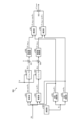
- FIG. 2 is a block diagram showing a configuration example of a control device included in the power conversion device according to Embodiment 1;
- the first diagram for explaining the problem of the present application A second diagram for explaining the problem of the present application
- FIG. 3 is a block diagram showing a configuration example of a voltage command value calculation unit included in the control device according to Embodiment 1;
- 4 is a block diagram showing a configuration example of a ⁇ -axis current command value generation unit provided in the voltage command value calculation unit according to Embodiment 1;
- FIG. 4 is a block diagram showing a first configuration example of a capacitor output current control section included in the voltage command value calculation section according to the first embodiment;
- FIG. 4 is a block diagram showing a second configuration example of the capacitor output current control section included in the voltage command value calculation section according to the first embodiment;
- FIG. 4 is a diagram for explaining the effect of the pulsation reduction control according to the first embodiment;
- FIG. FIG. 2 is a diagram showing an example of a hardware configuration that implements a control device included in the power conversion device according to Embodiment 1;
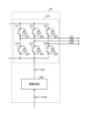
- FIG. 1 is a diagram showing a configuration example of a power conversion device 2 according to Embodiment 1.
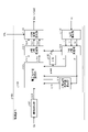
- FIG. 2 is a diagram showing a configuration example of the inverter 30 included in the power conversion device 2 according to Embodiment 1.
- the power converter 2 is connected to the AC power supply 1 and the compressor 8 .
- the compressor 8 is an example of a load that has a characteristic that the load torque periodically fluctuates when it is driven.
- the compressor 8 has an electric motor 7 .
- An example of the motor 7 is a three-phase permanent magnet synchronous motor.
- the power converter 2 converts the power supply voltage applied from the AC power supply 1 into an AC voltage having a desired amplitude and phase, and applies the AC voltage to the electric motor 7 .
- the power conversion device 2 includes a reactor 4 , a converter 10 , a capacitor 20 , an inverter 30 , a voltage detection section 82 , a current detection section 84 and a control device 100 .
- An electric motor driving device 50 is configured by the power conversion device 2 and the electric motor 7 included in the compressor 8 .
- the converter 10 has four diodes D1, D2, D3 and D4. Four diodes D1 to D4 are bridge-connected to form a rectifier circuit. Converter 10 rectifies the power supply voltage applied from AC power supply 1 by means of a rectifier circuit composed of four diodes D1 to D4. In converter 10 , one end on the input side is connected to AC power supply 1 via reactor 4 , and the other end on the input side is connected to AC power supply 1 . Also, in the converter 10 , the output side is connected to the capacitor 20 .
- the converter 10 may have a rectifying function as well as a boosting function for boosting the rectified voltage.
- a converter having a boosting function can be configured with one or more transistor elements or one or more switching elements in which a transistor element and a diode are connected in anti-parallel in addition to or instead of a diode. Note that the arrangement and connection of transistor elements or switching elements in a converter having a boosting function are well known, and description thereof will be omitted here.
- the capacitor 20 is connected to the output end of the converter 10 via DC buses 22a and 22b.
- the DC bus 22a is a positive side DC bus
- the DC bus 22b is a negative side DC bus.
- Capacitor 20 smoothes the rectified voltage applied from converter 10 .
- Examples of the capacitor 20 include an electrolytic capacitor, a film capacitor, and the like.
- the inverter 30 is connected across the capacitor 20 via DC buses 22a and 22b.
- the inverter 30 converts the DC voltage smoothed by the capacitor 20 into AC voltage for the compressor 8 and applies it to the electric motor 7 of the compressor 8 .
- the voltage applied to the electric motor 7 is a three-phase AC voltage with variable frequency and voltage value.
- the inverter 30 includes an inverter main circuit 310 and a drive circuit 350, as shown in FIG.
- the inverter main circuit 310 includes switching elements 311-316. Freewheeling rectifying elements 321 to 326 are connected in anti-parallel to the switching elements 311 to 316, respectively.
- the switching elements 311 to 316 are assumed to be IGBTs (Insulated Gate Bipolar Transistors), MOSFETs (Metal-Oxide-Semiconductor Field-Effect Transistors), etc., but elements capable of switching If so, you can use whatever you want.
- the switching elements 311 to 316 are MOSFETs, the MOSFETs have parasitic diodes due to their structure, so that the same effect can be obtained without connecting the freewheeling rectifying elements 321 to 326 in anti-parallel.
- switching elements 311 to 316 not only silicon (Si) but also wide bandgap semiconductors such as silicon carbide (SiC), gallium nitride (GaN), and diamond may be used. By forming switching elements 311 to 316 using a wide bandgap semiconductor, loss can be further reduced.
- the drive circuit 350 generates drive signals Sr1-Sr6 based on PWM (Pulse Width Modulation) signals Sm1-Sm6 output from the control device 100.
- PWM Pulse Width Modulation
- the drive circuit 350 controls on/off of the switching elements 311-316 by the drive signals Sr1-Sr6.
- the inverter 30 can apply the frequency-variable and voltage-variable three-phase AC voltage to the electric motor 7 via the output lines 331 to 333 .
- the PWM signals Sm1 to Sm6 are signals having a signal level of a logic circuit, for example, a magnitude of 0V to 5V.
- the PWM signals Sm1 to Sm6 are signals having the ground potential of the control device 100 as a reference potential.
- the driving signals Sr1 to Sr6 are signals having voltage levels necessary to control the switching elements 311 to 316, eg, -15V to +15V.
- the drive signals Sr1 to Sr6 are signals having the potential of the negative terminal, that is, the emitter terminal of the corresponding switching element as a reference potential.
- the voltage detection unit 82 detects the voltage across the capacitor 20 to detect the bus voltage Vdc.
- the bus voltage Vdc is the voltage between the DC buses 22a and 22b.
- the voltage detection unit 82 includes, for example, a voltage dividing circuit that divides the voltage with series-connected resistors.
- the voltage detection unit 82 converts the detected bus voltage Vdc into a voltage suitable for processing in the control device 100 using a voltage dividing circuit, for example, a voltage of 5 V or less, and outputs it to the control device 100 as a voltage detection signal that is an analog signal.
- the voltage detection signal output from the voltage detection unit 82 to the control device 100 is converted from an analog signal to a digital signal by an AD (Analog to Digital) conversion unit (not shown) in the control device 100, and is subjected to internal processing in the control device 100. Used.
- AD Analog to Digital
- the current detector 84 has a shunt resistor inserted in the DC bus 22b.
- a current detector 84 detects the capacitor output current idc using a shunt resistor.
- a capacitor output current idc is an input current to the inverter 30 , that is, a current output from the capacitor 20 to the inverter 30 .
- the current detection unit 84 outputs the detected capacitor output current idc to the control device 100 as a current detection signal, which is an analog signal.
- a current detection signal output from the current detection unit 84 to the control device 100 is converted from an analog signal to a digital signal by an AD conversion unit (not shown) in the control device 100 and used for internal processing in the control device 100 .
- the control device 100 controls the operation of the inverter 30 by generating the PWM signals Sm1 to Sm6 described above. Specifically, the control device 100 changes the angular frequency ⁇ e and the voltage value of the output voltage of the inverter 30 based on the PWM signals Sm1 to Sm6.
- the angular frequency ⁇ e of the output voltage of the inverter 30 determines the rotational angular velocity of the electric motor 7 in electrical angle.
- this rotational angular velocity is also represented by the same symbol ⁇ e.
- the rotational angular velocity ⁇ m of the electric motor 7 in the mechanical angle is equal to the rotational angular velocity ⁇ e of the electric motor 7 in the electrical angle divided by the pole logarithm P. Therefore, there is a relationship represented by the following equation (1) between the rotational angular velocity ⁇ m of the electric motor 7 in mechanical angle and the angular frequency ⁇ e of the output voltage of the inverter 30 .
- the rotational angular velocity is sometimes simply referred to as "rotational velocity”
- the angular frequency is simply referred to as "frequency”.
- FIG. 3 is a block diagram showing a configuration example of the control device 100 included in the power conversion device 2 according to Embodiment 1. As shown in FIG.
- the control device 100 includes an operation control section 102 and an inverter control section 110 .
- the operation control unit 102 receives command information Qe from the outside and generates a frequency command value ⁇ e* based on this command information Qe.
- the frequency command value ⁇ e* can be obtained by multiplying the rotational speed command value ⁇ m*, which is the command value of the rotational speed of the electric motor 7, by the number of pole pairs P, as shown in the following equation (2).
- the control device 100 controls the operation of each part of the air conditioner based on the command information Qe.
- the command information Qe is, for example, a temperature detected by a temperature sensor (not shown), information indicating a set temperature instructed from a remote controller (not shown), operation mode selection information, operation start/end instruction information, and the like. be.
- the operation modes are, for example, heating, cooling, and dehumidification.
- the operation control unit 102 may be outside the control device 100 . That is, the control device 100 may be configured to acquire the frequency command value ⁇ e* from the outside.
- Inverter control unit 110 includes current restoration unit 111, 3-phase 2-phase conversion unit 112, ⁇ -axis current command value generation unit 113, voltage command value calculation unit 115, electrical phase calculation unit 116, 2-phase 3-phase A converter 117 and a PWM signal generator 118 are provided.
- the current restoration unit 111 restores the phase currents iu, iv, and iw flowing through the electric motor 7 based on the capacitor output current idc detected by the current detection unit 84 .
- the current restoration unit 111 samples the detected value of the capacitor output current idc detected by the current detection unit 84 at timing determined based on the PWM signals Sm1 to Sm6 generated by the PWM signal generation unit 118.
- the currents iu, iv, iw can be restored.
- current detectors may be provided on the output lines 331 to 333 to directly detect the phase currents iu, iv, and iw and input them to the three-to-two-phase converter 112 . In this configuration, the current restoration section 111 is unnecessary.
- the three-phase to two-phase conversion unit 112 converts the phase currents iu, iv, and iw restored by the current restoration unit 111 into the ⁇ axis, which is the excitation current, using the electric phase ⁇ e generated by the electric phase calculation unit 116, which will be described later.
- the current i ⁇ and the ⁇ -axis current i ⁇ , which is the torque current, are converted into ⁇ - ⁇ axis current values.
- a ⁇ -axis current command value generation unit 113 generates a ⁇ -axis current command value i ⁇ *, which is an exciting current command value, based on the ⁇ -axis current i ⁇ . More specifically, the ⁇ -axis current command value generation unit 113 obtains the current phase angle at which the output torque of the electric motor 7 is equal to or higher than the set value or the maximum value based on the ⁇ -axis current i ⁇ , and the calculated current phase angle is Based on this, the ⁇ -axis current command value i ⁇ * is calculated. Note that the motor current flowing through the electric motor 7 may be used instead of the output torque of the electric motor 7 . In this case, the ⁇ -axis current command value i ⁇ * is calculated based on the current phase angle at which the motor current flowing through the motor 7 is the set value or less or the minimum value.
- FIG. 3 shows a configuration in which the ⁇ -axis current command value i ⁇ * is obtained based on the ⁇ -axis current i ⁇ , it is not limited to this configuration.
- the ⁇ -axis current command value i ⁇ * may be obtained based on the ⁇ -axis current i ⁇ instead of the ⁇ -axis current i ⁇ .
- the ⁇ -axis current command value generator 113 may determine the ⁇ -axis current command value i ⁇ * by flux-weakening control.
- the voltage command value calculation unit 115 calculates the frequency command value ⁇ e* obtained from the operation control unit 102, the ⁇ -axis current i ⁇ and the ⁇ -axis current i ⁇ obtained from the three-phase to two-phase conversion unit 112, and the ⁇ -axis current command value generation unit. Based on the ⁇ -axis current command value i ⁇ * acquired from 113, the ⁇ -axis voltage command value V ⁇ * and the ⁇ -axis voltage command value V ⁇ * are generated. Furthermore, the voltage command value calculator 115 estimates the frequency estimation value ⁇ est based on the ⁇ -axis voltage command value V ⁇ *, the ⁇ -axis voltage command value V ⁇ *, the ⁇ -axis current i ⁇ , and the ⁇ -axis current i ⁇ . .
- the electrical phase calculator 116 calculates the electrical phase ⁇ e by integrating the frequency estimation value ⁇ est acquired from the voltage command value calculator 115 .
- the two-to-three phase conversion unit 117 converts the ⁇ -axis voltage command value V ⁇ * and the ⁇ -axis voltage command value V ⁇ * acquired from the voltage command value calculation unit 115, that is, the voltage command values in the two-phase coordinate system, to the electric phase calculation unit 116. are converted into three-phase voltage command values Vu*, Vv*, Vw*, which are output voltage command values in a three-phase coordinate system, using the electric phase ⁇ e obtained from .
- the PWM signal generator 118 compares the three-phase voltage command values Vu*, Vv*, Vw* acquired from the two-to-three-phase converter 117 with the bus voltage Vdc detected by the voltage detector 82. PWM signals Sm1 to Sm6 are generated. The PWM signal generator 118 can also stop the electric motor 7 by not outputting the PWM signals Sm1 to Sm6.
- 4 and 5 are first and second diagrams, respectively, for explaining the problem of the present application.
- the problem of the present application was briefly described in the section [Problems to be Solved by the Invention], but a more detailed description will be added here.
- vibration suppression control when the load is a load having torque pulsation, such as a single rotary compressor, a scroll compressor, or a twin rotary compressor, control is performed to compensate for this torque pulsation, as described in the Background Art section.
- This control is also called “vibration suppression control”.
- the inverter 30 is controlled by generating a torque current compensation value so that the output torque of the electric motor 7 follows torque pulsation.
- this control is simply performed, as explained in the section [Problems to be Solved by the Invention], the capacitor output current idc becomes unbalanced between the positive and negative power supply currents. A problem arises in that the harmonic components of are increased.
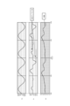
- FIGS. 4 and 5 show the waveforms of the power supply voltage Vin, the power supply current Iin, and the capacitor output current idc in order from the top.
- the horizontal axes in FIGS. 4 and 5 represent time.
- the peak value of the positive side waveform and the peak value of the negative side waveform of the power supply current Iin are different, that is, the peak value is unbalanced between the positive and negative polarities of the power supply current Iin. It is shown.
- pulsation occurs in the capacitor output current idc as shown in the lower part.
- the power supply current Iin contains many harmonic components.
- the inventors of the present application have found that the pulsation of the capacitor output current idc increases as the load torque increases and the inertia of the load decreases. It is also, the inventors of the present application have found that the pulsation of the capacitor output current idc is greater in the single rotary compressor than in the twin rotary compressor and the scroll compressor.
- the lower part of FIG. 5 shows an ideal state in which the capacitor output current idc is constant. In such an ideal state, as shown in the middle part of FIG. imbalance does not occur. Therefore, the harmonic components that can be included in the power supply current Iin are much smaller than in the case of FIG.
- voltage command value calculation unit 115 included in control device 100 performs control to reduce pulsation of capacitor output current idc when the load is driven.
- a specific configuration is as shown in FIGS. 6 and 7. FIG.
- FIG. 6 is a block diagram showing a configuration example of voltage command value calculation section 115 included in control device 100 according to the first embodiment.
- voltage command value calculation unit 115 includes frequency estimation unit 501, subtraction units 502, 509, 510, ⁇ -axis current command value generation unit 503, capacitor output current control unit 504, ⁇ -axis A current control unit 511 and a ⁇ -axis current control unit 512 are provided.
- FIG. 7 is a block diagram showing a configuration example of ⁇ -axis current command value generation section 503 included in voltage command value calculation section 115 according to the first embodiment. Note that FIG. 7 also shows a subtraction unit 502 positioned before the ⁇ -axis current command value generation unit 503 .
- Frequency estimator 501 estimates the frequency of the voltage applied to electric motor 7 based on ⁇ -axis current i ⁇ , ⁇ -axis current i ⁇ , ⁇ -axis voltage command value V ⁇ *, and ⁇ -axis voltage command value V ⁇ *. and outputs the estimated frequency as the frequency estimation value ⁇ est.
- the subtraction unit 502 calculates the difference ( ⁇ e* ⁇ est) between the frequency command value ⁇ e* and the frequency estimation value ⁇ est estimated by the frequency estimation unit 501 .
- a capacitor output current control unit 504 generates a ⁇ -axis current compensation value i ⁇ _lcc* based on the capacitor output current idc acquired from the current detection unit 84 .
- the ⁇ -axis current compensation value i ⁇ _lcc* is a control amount component for reducing the ripple component of the capacitor output current idc. Details of the ⁇ -axis current compensation value i ⁇ _lcc* will be described later.
- the capacitor output current control unit is sometimes simply called “current control unit”
- the ⁇ -axis current compensation value is sometimes simply called "current compensation value”.
- a ⁇ -axis current command value generation unit 503 generates a ⁇ -axis current command value i ⁇ **, which is a torque current command value in a rotating coordinate system. More specifically, the ⁇ -axis current command value generating unit 503 performs proportional integral calculation, that is, PI (Proportional Integral) control on the difference ( ⁇ e* ⁇ est) calculated by the subtracting unit 502 to obtain the difference A ⁇ -axis current command value i ⁇ * that brings ( ⁇ e* ⁇ est) close to zero is obtained.
- PI Proportional Integral
- the ⁇ -axis current command value generation unit 503 generates the ⁇ -axis current command value i ⁇ * based on the ⁇ -axis current command value i ⁇ * and the ⁇ -axis current compensation value i ⁇ _lcc* acquired from the capacitor output current control unit 504. A corrected or compensated ⁇ -axis current command value i ⁇ ** is generated and output.
- FIG. 7 shows a configuration example of the ⁇ -axis current command value generating section 503.
- the ⁇ -axis current command value generator 503 includes a speed controller 610 and a compensator 620 .
- Speed control unit 610 is a control unit that generates a current command value based on the frequency deviation.
- the speed control section 610 includes a proportional control section 611 , an integral control section 612 and an addition section 613 , and the compensation section 620 includes an addition section 621 .
- proportional control unit 611 performs proportional control on the difference ( ⁇ e*- ⁇ est) between frequency command value ⁇ e* and frequency estimated value ⁇ est obtained from subtraction unit 502, and proportional term i ⁇ _p* to output
- the integral control unit 612 performs integral control on the difference ( ⁇ e* ⁇ est) between the frequency command value ⁇ e* and the frequency estimated value ⁇ est obtained from the subtraction unit 502, and outputs an integral term i ⁇ _i*.
- the addition unit 613 adds the proportional term i ⁇ _p* obtained from the proportional control unit 611 and the integral term i ⁇ _i* obtained from the integral control unit 612 to generate the ⁇ -axis current command value i ⁇ *.
- Addition unit 621 adds ⁇ -axis current command value i ⁇ * generated by speed control unit 610 and ⁇ -axis current compensation value i ⁇ _lcc* obtained from capacitor output current control unit 504 to obtain ⁇ -axis current command value i ⁇ Generate **.
- the ⁇ -axis current command value i.delta.* is called “first .delta.-axis current command value” and the .delta.-axis current command value i.delta.** is called “second .delta.-axis current command value.”
- the ⁇ -axis current command value generation unit 503 performs control for suppressing pulsation of the capacitor output current idc while matching the frequency estimation value ⁇ est with the frequency command value ⁇ e*.
- the subtraction unit 509 calculates the difference (i ⁇ *-i ⁇ ) between the ⁇ -axis current command value i ⁇ * and the ⁇ -axis current i ⁇ .
- Subtraction unit 510 calculates a difference (i ⁇ **-i ⁇ ) between ⁇ -axis current command value i ⁇ ** and ⁇ -axis current i ⁇ .
- the ⁇ -axis current control unit 511 performs a proportional integral operation on the difference (i ⁇ * ⁇ i ⁇ ) calculated by the subtraction unit 509 to bring the difference (i ⁇ * ⁇ i ⁇ ) closer to zero. to generate The ⁇ -axis current control unit 511 generates such a ⁇ -axis voltage command value V ⁇ * to perform control so that the ⁇ -axis current i ⁇ matches the ⁇ -axis current command value i ⁇ *.
- a ⁇ -axis current control unit 512 performs a proportional integral operation on the difference (i ⁇ **-i ⁇ ) calculated by the subtraction unit 510 to obtain a ⁇ -axis voltage command value that brings the difference (i ⁇ **-i ⁇ ) closer to zero. Generate V ⁇ *.
- the ⁇ -axis current control unit 512 generates such a ⁇ -axis voltage command value V ⁇ * to perform control so that the ⁇ -axis current i ⁇ matches the ⁇ -axis current command value i ⁇ **.
- the ⁇ -axis current command value i ⁇ ** input to the ⁇ -axis current control unit 512 includes the ⁇ -axis current compensation value i ⁇ _lcc* obtained from the capacitor output current control unit 504 .
- the ⁇ -axis current control unit 512 controls the inverter 30 based on the ⁇ -axis voltage command value V ⁇ * generated based on the ⁇ -axis current compensation value i ⁇ _lcc*, thereby suppressing the pulsation of the capacitor output current idc. can be done.
- FIG. 8 is a block diagram showing a first configuration example of capacitor output current control section 504 included in voltage command value calculation section 115 according to the first embodiment.
- the capacitor output current control unit 504 includes a calculation unit 550, a cosine calculation unit 551, a sine calculation unit 552, multiplication units 553, 554, 561, 562, low-pass filters 555, 556, subtraction units 557, 558, It includes frequency control units 559 and 560 and an addition unit 563 .
- the computing unit 550 computes the phase angle ⁇ x with respect to the frequency ⁇ x of the pulsating component of interest in the capacitor output current idc.
- the pulsating component of interest is the pulsating component to be reduced among the plurality of pulsating components included in the capacitor output current idc.
- the phase angle ⁇ x is determined by the frequency ⁇ x of the pulsating component to be reduced, the clock frequency of the processor that performs the processing, and the like.
- the cosine calculator 551 calculates the cosine value cos ⁇ x based on the phase angle ⁇ x.
- the sine calculator 552 calculates a sine value sin ⁇ x based on the phase angle ⁇ x.
- the multiplier 553 multiplies the capacitor output current idc by the cosine value cos ⁇ x to calculate the cosine component idc ⁇ cos ⁇ x of the capacitor output current idc.
- the multiplier 554 multiplies the capacitor output current idc by the sine value sin ⁇ x to calculate the sine component idc ⁇ sin ⁇ x of the capacitor output current idc.
- the cosine component idc ⁇ cos ⁇ x and the sine component idc ⁇ sin ⁇ x calculated by the multipliers 553 and 554 include a pulsation component with a frequency of ⁇ x and a pulsation component with a frequency higher than ⁇ x, that is, a harmonic component. ing.
- the low-pass filters 555 and 556 are first-order lag filters whose transfer function is represented by 1/(1+s ⁇ Tf). s is the Laplacian operator and Tf is the time constant. The time constant Tf is determined so as to remove pulsation components with frequencies higher than the frequency ⁇ x. Note that "removal” includes the case where part of the pulsation component is attenuated, that is, reduced.
- the time constant Tf is set by the operation control unit 102 based on the speed command value, and may be notified to the low-pass filters 555 and 556 by the operation control unit 102, or may be held by the low-pass filters 555 and 556. .
- a first-order lag filter is an example, and a moving average filter or the like may be used, and the type of filter is not limited as long as the pulsation component on the high frequency side can be removed.
- a low-pass filter 555 performs low-pass filtering on the cosine component idc ⁇ cos ⁇ x, removes frequency components higher than the frequency ⁇ x, and outputs a low frequency component idc_c.
- the low-frequency component idc_c is a cosine component with a frequency of ⁇ x among the ripple components of the capacitor output current idc.
- a low-pass filter 556 performs low-pass filtering on the sine component idc ⁇ sin ⁇ x, removes frequency components higher than the frequency ⁇ x, and outputs a low frequency component idc_s.
- the low-frequency component idc_s is a sinusoidal component with a frequency of ⁇ x among the ripple components of the capacitor output current idc.
- the subtraction unit 557 calculates the difference (idc_c-0) between the low frequency component idc_c output from the low-pass filter 555 and zero.
- the subtraction unit 558 calculates the difference (idc_s ⁇ 0) between the low frequency component idc_s output from the low-pass filter 556 and zero.
- the frequency control unit 559 performs an integral operation on the difference (idc_c-0) calculated by the subtraction unit 557 to calculate the cosine component i ⁇ _trq_c of the current command value that brings the difference (idc_c-0) closer to zero. By generating the cosine component i ⁇ _trq_c in this manner, the frequency control unit 559 performs control to match the low frequency component idc_c to zero.
- the integral calculation here is an example, and a proportional integral calculation may be performed instead of the integral calculation.
- the frequency control unit 560 performs an integral operation on the difference (idc_s-0) calculated by the subtraction unit 558 to calculate the sine component i ⁇ _trq_s of the current command value that brings the difference (idc_s-0) close to zero.
- the frequency control unit 560 generates the sine component i ⁇ _trq_s in this way, thereby performing control to match the low frequency component idc_s to zero.
- the integral calculation here is an example, and a proportional integral calculation may be performed instead of the integral calculation.
- the multiplier 561 multiplies the cosine component i ⁇ _trq_c output from the frequency control unit 559 by the cosine value cos ⁇ x to generate i ⁇ _trq_c ⁇ cos ⁇ x.
- the multiplier 562 multiplies the sine component i ⁇ _trq_s output from the frequency control unit 560 by the sine value sin ⁇ x to generate i ⁇ _trq_s ⁇ sin ⁇ x.
- the addition unit 563 obtains the sum of i ⁇ _trq_c ⁇ cos ⁇ x output from the multiplication unit 561 and i ⁇ _trq_s ⁇ sin ⁇ x output from the multiplication unit 562 .
- the capacitor output current control unit 504 outputs the value obtained by the adding unit 563 as the ⁇ -axis current compensation value i ⁇ _lcc*.
- control device 100 performs control to reduce pulsation of the capacitor output current idc output from the capacitor 20 to the inverter 30 when the compressor 8 is driven. With this control, it is possible to avoid an unbalanced state between the positive and negative polarities of the power supply current Iin. This makes it possible to suppress an increase in harmonic components that may be included in the power supply current Iin.
- the motor power which is the power applied from the inverter 30 to the electric motor 7, is represented by Pm.
- This motor power Pm can be expressed by the following equation (3).
- V ⁇ i ⁇ +V ⁇ i ⁇ (Ra i ⁇ - ⁇ e L ⁇ i ⁇ ) i ⁇ + ⁇ Ra ⁇ i ⁇ + ⁇ e (L ⁇ ⁇ i ⁇ + ⁇ a) ⁇ ⁇ i ⁇ ...(3)
- V ⁇ ⁇ -axis voltage in electric motor 7
- V ⁇ ⁇ -axis voltage in electric motor 7
- i ⁇ ⁇ -axis current flowing in electric motor 7
- Ra phase resistance in electric motor 7
- ⁇ e frequency of output voltage of inverter 30 (electrical angle)
- L ⁇ ⁇ -axis inductance in the electric motor 7
- L ⁇ ⁇ -axis inductance in the electric motor 7
- ⁇ a Induced voltage constant in the electric motor 7
- the mechanical 1f component is the most dominant frequency component among the pulsating components contained in the capacitor output current idc.
- the mechanical 1f component is one times the mechanical angular frequency of the electric motor 7, that is, a mechanical angular frequency component.
- the pulsation component that depends on the mechanical angular frequency of the electric motor 7 and the power supply frequency, which is the frequency of the power supply voltage Vin, also increases.
- the frequency of this pulsating component can be expressed by the following equation (6).
- the dominant component of the bus voltage Vdc is the component twice the power supply frequency. This component is denoted as "power supply 2f". Therefore, when the mechanical 1f component is removed, the following components are large pulsating components.
- " represents the absolute value of the numerical value a.
- the components that greatly affect the harmonics of the power supply current Iin are the components with large absolute values and the components with low frequencies.
- the mechanical 2f component increases as the rotation speed increases, and the
- the lower the frequency the greater the effect of contributing to the harmonics of the power supply current Iin. Therefore, if there is a limit to the number of pulsation components to be reduced, the frequency components to be reduced are changed according to the rotation speed. For example, when the number of pulsation components to be reduced is two, the control device 100 reduces the following pulsation components.
- FIG. 8 shows a configuration example of capacitor output current control section 504 when the number of pulsating components to be reduced is one. can.
- FIG. 9 is a block diagram showing a second configuration example of capacitor output current control section 504 included in voltage command value calculation section 115 according to the first embodiment. Note that FIG. 9 shows a configuration example in which the number of pulsation components to be reduced is three.
- the first ⁇ -axis current compensation value i ⁇ m1f* is calculated based on the phase angle ⁇ m1f of the pulsation component of the machine 1f.
- the second ⁇ -axis current compensation value i ⁇ m2f* is calculated based on the phase angle ⁇ m2f of the pulsating component of the machine 2f.
- the first ⁇ -axis current compensation value i ⁇ m1f*, the second ⁇ -axis current compensation value i ⁇ m2f*, and the third ⁇ -axis current compensation value i ⁇ y* are added in an adder 564 to obtain the ⁇ -axis current compensation value i ⁇ _lcc*. is output as
- FIG. 9 shows a case where the number of pulsation components to be reduced is three, the number is not limited to three. Even when the number of pulsating components to be reduced is 2 or 4 or more, as in FIG. 9, a control system for generating the ⁇ -axis current compensation value i ⁇ _lcc* is configured in parallel and added at the final stage. It can be realized by
- FIG. 10 is a diagram for explaining the effect of the pulsation reduction control according to Embodiment 1.
- FIG. The left part of FIG. 10 shows the waveforms of the power supply current and the capacitor output current when the capacitor output current control unit 504 is not provided in the voltage command value calculation unit 115 of FIG.
- the right part of FIG. 10 shows the waveforms of the power supply current and the capacitor output current when the capacitor output current control unit 504 is provided, that is, when the voltage command value calculation unit 115 of FIG. 6 is used.
- the pulsation of the capacitor output current is large, as shown in the left part of FIG. It is shown that this causes the peak value of the power supply current to fluctuate and the harmonic components contained in the power supply current to increase.
- the capacitor output current control section 504 when the capacitor output current control section 504 is provided, the pulsation of the capacitor output current is reduced as shown in the right part of FIG. It is shown that this makes the peak value of the power supply current substantially constant and reduces the harmonic components contained in the power supply current.
- the power converter according to Embodiment 1 performs control to reduce pulsation of the capacitor output current output from the capacitor to the inverter when driving the load.
- This control avoids an unbalanced state between the positive and negative polarities of the power supply current. This makes it possible to suppress an increase in harmonic components that may be included in the power supply current.
- the unbalanced state between the positive and negative sides of the power supply current is suppressed, it becomes easier to comply with the power supply harmonic standard. This eliminates the need to change or modify the circuit constants of the converter and the switching method of the converter, making it possible to obtain an inexpensive and highly reliable electric motor drive device.
- the power factor of the power supply increases due to the reduction of the harmonics of the power supply, it is no longer necessary to flow wasteful current. As a result, efficiency on the converter side can be increased, and a highly efficient electric motor drive device can be obtained.
- the control device performs control to reduce at least the pulsating component that depends on the mechanical angular frequency of the electric motor among the pulsating components contained in the capacitor output current. preferably.
- the control device reduces, among the pulsation components dependent on the mechanical angular frequency, particularly the first pulsation component caused by the mechanical angular frequency. This first pulsation component is dominant when the rotation speed of the motor is low, medium, or high. Therefore, if the first pulsating component can be reduced, it can greatly contribute to the reduction of harmonics of the power supply current.
- first pulsation component is the mechanical 1f component mentioned above.
- second pulsation component caused by a frequency twice the mechanical angular frequency may be added.
- mechanical 2f component is the mechanical 2f component mentioned above.
- the control device reduces at least one pulsation component dependent on both the power supply frequency and the mechanical angular frequency in addition to the first pulsation component. It is preferable to perform control to reduce the pulsation component.
- One of the pulsation components that depends on both the power supply frequency and the mechanical angular frequency is the third pulsation component resulting from the absolute value of the frequency difference between twice the power supply frequency and the mechanical angular frequency.
- Another pulsation component that depends on both the power supply frequency and the mechanical angular frequency is the absolute value of the frequency difference between twice the power supply frequency and twice the mechanical angular frequency. 4 pulsation component.
- An example of the third pulsation component is the aforementioned
- an example of the fourth pulsation component is the aforementioned
- the control device preferably changes the pulsation component to be reduced based on the mechanical angular frequency.
- the above-described second to fourth pulsation components are reversed in size according to the mechanical angular frequency. Therefore, by changing the pulsation component to be reduced based on the mechanical angular frequency, even if the scale of the control system is small, efficient control with a high reduction effect can be performed.
- control device preferably performs control to preferentially reduce the pulsation component with a lower frequency among the second, third, and fourth pulsation components.
- the component that greatly affects the harmonics of the power supply current is the pulsating component with a low frequency. Therefore, if control is performed to preferentially reduce pulsation components with lower frequencies, efficient control with a high reduction effect can be performed even if the scale of the control system is small.
- FIG. 11 is a diagram showing an example of a hardware configuration that implements the control device 100 included in the power conversion device 2 according to Embodiment 1. As shown in FIG. The control device 100 is implemented by a processor 201 and memory 202 .
- the processor 201 is a CPU (Central Processing Unit, central processing unit, processing unit, arithmetic unit, microprocessor, microcomputer, processor, DSP (Digital Signal Processor)), or a system LSI (Large Scale Integration).
- the memory 202 may be RAM (Random Access Memory), ROM (Read Only Memory), flash memory, EPROM (Erasable Programmable Read Only Memory), EEPROM (registered trademark) (Electrically Erasable Programmable Read Only Memory), non-volatile or non-volatile memory such as can be exemplified. Also, the memory 202 is not limited to these, and may be a magnetic disk, an optical disk, a compact disk, a mini disk, or a DVD (Digital Versatile Disc).
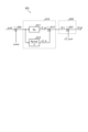
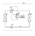
- FIG. 12 is a diagram showing a configuration example of a refrigeration cycle equipment 900 according to Embodiment 2.
- a refrigerating cycle applied equipment 900 according to the second embodiment includes the power converter 2 described in the first embodiment.
- the refrigerating cycle applied equipment 900 according to Embodiment 2 can be applied to products equipped with a refrigerating cycle, such as air conditioners, refrigerators, freezers, and heat pump water heaters.
- constituent elements having functions similar to those of the first embodiment are assigned the same reference numerals as those of the first embodiment.
- a refrigerating cycle application device 900 includes a compressor 901 incorporating the electric motor 7 according to Embodiment 1, a four-way valve 902, an indoor heat exchanger 906, an expansion valve 908, and an outdoor heat exchanger 910 with a refrigerant pipe 912. attached through
- a compression mechanism 904 for compressing refrigerant and an electric motor 7 for operating the compression mechanism 904 are provided inside the compressor 901 .
- the refrigeration cycle applied equipment 900 can perform heating operation or cooling operation by switching operation of the four-way valve 902 .
- Compression mechanism 904 is driven by electric motor 7 whose speed is controlled.
- the refrigerant is pressurized by the compression mechanism 904 and sent out through the four-way valve 902, the indoor heat exchanger 906, the expansion valve 908, the outdoor heat exchanger 910, and the four-way valve 902. Return to compression mechanism 904 .
- the refrigerant is pressurized by the compression mechanism 904 and sent through the four-way valve 902, the outdoor heat exchanger 910, the expansion valve 908, the indoor heat exchanger 906, and the four-way valve 902. Return to compression mechanism 904 .
- the indoor heat exchanger 906 acts as a condenser to release heat, and the outdoor heat exchanger 910 acts as an evaporator to absorb heat.
- the outdoor heat exchanger 910 acts as a condenser to release heat, and the indoor heat exchanger 906 acts as an evaporator to absorb heat.
- the expansion valve 908 reduces the pressure of the refrigerant to expand it.
Landscapes
- Engineering & Computer Science (AREA)
- Power Engineering (AREA)
- Control Of Ac Motors In General (AREA)
Abstract
電力変換装置(2)は、交流電源(1)から印加される電源電圧を整流するコンバータ(10)、コンバータ(10)の出力端に接続されるコンデンサ(20)、コンデンサ(20)の両端に接続されるインバータ(30)及びインバータ(30)の動作を制御する制御装置(100)を備える。制御装置(100)は、負荷の駆動時にコンデンサ(20)からインバータ(30)に出力されるコンデンサ出力電流の脈動を低減する制御を行う。
Description
本開示は、負荷を駆動する電動機に交流電力を供給する電力変換装置、電動機駆動装置及び冷凍サイクル適用機器に関する。
電力変換装置は、交流電源から印加される電源電圧を整流するコンバータと、コンバータの出力端に接続されるコンデンサと、コンデンサから出力される直流電圧を交流電圧に変換して電動機に印加するインバータと、を備える。
下記特許文献1には、圧縮機を駆動する電動機の状態に応じて、負荷トルクの脈動成分であるトルク脈動を適切に補償することで消費電力の増加を抑制する技術が開示されている。
冷凍サイクル適用機器の応用製品の1つである空気調和機においては、電源電流に含まれる高調波成分による障害を抑制するため、電源電流の高調波に関する規制が定められている。例えば、日本国内においては、日本工業規格(JIS)によって電源電流の高調波に対して制限値が定められている。
しかしながら、特許文献1に記載の技術では、電源電流の高調波に関する考慮がなされていない。このため、特許文献1の技術を使用して、電源周波数と非同期の周波数で電動機のトルク脈動の補償成分を発生させると、電源電流がその極性の正と負との間でアンバランス状態となり、電源電流の高調波成分が増加してしまうという問題がある。
本開示は、上記に鑑みてなされたものであって、電源電流の高調波成分の増加を抑制できる電力変換装置を得ることを目的とする。
上述した課題を解決し、目的を達成するため、本開示に係る電力変換装置は、負荷を駆動する電動機に交流電力を供給する電力変換装置である。電力変換装置は、交流電源から印加される電源電圧を整流するコンバータと、コンバータの出力端に接続されるコンデンサとを備える。また、電力変換装置は、コンデンサの両端に接続されるインバータと、インバータの動作を制御する制御装置とを備える。制御装置は、負荷の駆動時にコンデンサからインバータに出力されるコンデンサ出力電流の脈動を低減する制御を行う。
本開示に係る電力変換装置によれば、電源電流の高調波成分の増加を抑制できるという効果を奏する。
以下に添付図面を参照し、本開示の実施の形態に係る電力変換装置、電動機駆動装置及び冷凍サイクル適用機器について詳細に説明する。
実施の形態1.
図1は、実施の形態1に係る電力変換装置2の構成例を示す図である。図2は、実施の形態1に係る電力変換装置2が備えるインバータ30の構成例を示す図である。電力変換装置2は、交流電源1及び圧縮機8に接続される。圧縮機8は、被駆動時に負荷トルクが周期的に変動する特性を有する負荷の一例である。圧縮機8は、電動機7を有する。電動機7の一例は、3相永久磁石同期電動機である。電力変換装置2は、交流電源1から印加される電源電圧を所望の振幅及び位相を有する交流電圧に変換して電動機7に印加する。電力変換装置2は、リアクタ4と、コンバータ10と、コンデンサ20と、インバータ30と、電圧検出部82と、電流検出部84と、制御装置100と、を備える。電力変換装置2と、圧縮機8が備える電動機7とによって、電動機駆動装置50が構成される。
図1は、実施の形態1に係る電力変換装置2の構成例を示す図である。図2は、実施の形態1に係る電力変換装置2が備えるインバータ30の構成例を示す図である。電力変換装置2は、交流電源1及び圧縮機8に接続される。圧縮機8は、被駆動時に負荷トルクが周期的に変動する特性を有する負荷の一例である。圧縮機8は、電動機7を有する。電動機7の一例は、3相永久磁石同期電動機である。電力変換装置2は、交流電源1から印加される電源電圧を所望の振幅及び位相を有する交流電圧に変換して電動機7に印加する。電力変換装置2は、リアクタ4と、コンバータ10と、コンデンサ20と、インバータ30と、電圧検出部82と、電流検出部84と、制御装置100と、を備える。電力変換装置2と、圧縮機8が備える電動機7とによって、電動機駆動装置50が構成される。
コンバータ10は、4つのダイオードD1,D2,D3,D4を備える。4つのダイオードD1~D4は、ブリッジ接続され、整流回路を構成する。コンバータ10は、4つのダイオードD1~D4から構成される整流回路によって、交流電源1から印加される電源電圧を整流する。コンバータ10において、入力側の一端はリアクタ4を介して交流電源1に接続され、入力側の他端は交流電源1に接続されている。また、コンバータ10において、出力側はコンデンサ20に接続されている。
コンバータ10は、整流機能と共に、整流電圧を昇圧する昇圧機能を有するものであってもよい。昇圧機能を有するコンバータは、ダイオードに加え、もしくはダイオードに代え、1以上のトランジスタ素子、もしくはトランジスタ素子とダイオードとが逆並列に接続された1以上のスイッチング素子を備えて構成することができる。なお、昇圧機能を有するコンバータにおけるトランジスタ素子又はスイッチング素子の配置、及び接続は公知であり、ここでの説明は省略する。
コンデンサ20は、直流母線22a,22bを介してコンバータ10の出力端に接続される。直流母線22aは正側の直流母線であり、直流母線22bは負側の直流母線である。コンデンサ20は、コンバータ10から印加される整流電圧を平滑する。コンデンサ20としては、電解コンデンサ、フィルムコンデンサなどが例示される。
インバータ30は、直流母線22a,22bを介してコンデンサ20の両端に接続される。インバータ30は、コンデンサ20によって平滑された直流電圧を圧縮機8への交流電圧に変換して、圧縮機8の電動機7に印加する。電動機7に印加される電圧は、周波数及び電圧値が可変の3相交流電圧である。
インバータ30は、図2に示すように、インバータ主回路310と、駆動回路350と、を備える。インバータ主回路310は、スイッチング素子311~316を備える。スイッチング素子311~316の各々には、還流用の整流素子321~326が逆並列接続されている。
インバータ主回路310において、スイッチング素子311~316としては、IGBT(Insulated Gate Bipolar Transistor)、MOSFET(Metal-Oxide-Semiconductor Field-Effect Transistor)などを想定しているが、スイッチングを行うことが可能な素子であれば、どのようなものを用いてもよい。なお、スイッチング素子311~316がMOSFETの場合、MOSFETは構造上、寄生ダイオードを有するため、還流用の整流素子321~326を逆並列接続しなくても同様の効果を得ることができる。
また、スイッチング素子311~316を形成する材料については、ケイ素(Si)だけでなく、ワイドバンドギャップ半導体である炭化ケイ素(SiC)、窒化ガリウム(GaN)、ダイヤモンド等を用いてもよい。ワイドバンドギャップ半導体を用いてスイッチング素子311~316を形成することにより、損失をより少なくすることが可能となる。
駆動回路350は、制御装置100から出力されるPWM(Pulse Width Modulation)信号Sm1~Sm6に基づいて、駆動信号Sr1~Sr6を生成する。駆動回路350は、駆動信号Sr1~Sr6によってスイッチング素子311~316のオンオフを制御する。これにより、インバータ30は、周波数可変、且つ電圧可変の3相交流電圧を、出力線331~333を介して電動機7に印加することができる。
PWM信号Sm1~Sm6は、論理回路の信号レベル、例えば、0V~5Vの大きさを持つ信号である。PWM信号Sm1~Sm6は、制御装置100の接地電位を基準電位とする信号である。一方、駆動信号Sr1~Sr6は、スイッチング素子311~316を制御するのに必要な電圧レベル、例えば、-15V~+15Vの大きさを持つ信号である。駆動信号Sr1~Sr6は、それぞれ対応するスイッチング素子の負側の端子、即ちエミッタ端子の電位を基準電位とする信号である。
電圧検出部82は、コンデンサ20の両端電圧を検出することで母線電圧Vdcを検出する。母線電圧Vdcは、直流母線22a,22b間の電圧である。電圧検出部82は、例えば直列接続された抵抗で分圧する分圧回路を備える。電圧検出部82は、検出した母線電圧Vdcを、分圧回路を用いて制御装置100での処理に適した電圧、例えば5V以下の電圧に変換し、アナログ信号である電圧検出信号として制御装置100に出力する。電圧検出部82から制御装置100に出力される電圧検出信号は、制御装置100内の図示しないAD(Analog to Digital)変換部によってアナログ信号からデジタル信号に変換され、制御装置100での内部処理に用いられる。
電流検出部84は、直流母線22bに挿入されたシャント抵抗を備える。電流検出部84は、シャント抵抗を用いて、コンデンサ出力電流idcを検出する。コンデンサ出力電流idcは、インバータ30への入力電流、即ちコンデンサ20からインバータ30に出力される電流である。電流検出部84は、検出したコンデンサ出力電流idcを、アナログ信号である電流検出信号として制御装置100に出力する。電流検出部84から制御装置100に出力される電流検出信号は、制御装置100内の図示しないAD変換部によってアナログ信号からデジタル信号に変換され、制御装置100での内部処理に用いられる。
制御装置100は、前述したPWM信号Sm1~Sm6を生成してインバータ30の動作を制御する。具体的に、制御装置100は、PWM信号Sm1~Sm6に基づいて、インバータ30の出力電圧の角周波数ωe及び電圧値を変化させる。
インバータ30の出力電圧の角周波数ωeは、電動機7の電気角での回転角速度を定めるものである。本稿では、この回転角速度も同じ符号ωeで表すことにする。電動機7の機械角での回転角速度ωmは、電動機7の電気角での回転角速度ωeを極対数Pで割ったものに等しい。従って、電動機7の機械角での回転角速度ωmと、インバータ30の出力電圧の角周波数ωeとの間には、以下の(1)式で表される関係がある。なお、本稿では、回転角速度を単に「回転速度」と称し、角周波数を単に「周波数」と称することがある。
ωm=ωe/P …(1)
次に、制御装置100の構成について説明する。図3は、実施の形態1に係る電力変換装置2が備える制御装置100の構成例を示すブロック図である。制御装置100は、運転制御部102と、インバータ制御部110と、を備える。
運転制御部102は、外部から指令情報Qeを受け、この指令情報Qeに基づいて、周波数指令値ωe*を生成する。周波数指令値ωe*は、以下の(2)式に示すように、電動機7の回転速度の指令値である回転速度指令値ωm*に極対数Pを乗算することで求めることができる。
ωe*=ωm*×P …(2)
制御装置100は、冷凍サイクル適用機器としての空気調和機を制御する場合、指令情報Qeに基づいて、空気調和機の各部の動作を制御する。指令情報Qeは、例えば、図示しない温度センサで検出された温度、図示しない操作部であるリモコンから指示される設定温度を示す情報、運転モードの選択情報、運転開始及び運転終了の指示情報などである。運転モードとは、例えば、暖房、冷房、除湿などである。なお、運転制御部102については、制御装置100の外部にあってもよい。即ち制御装置100は、外部から周波数指令値ωe*を取得する構成であってもよい。
インバータ制御部110は、電流復元部111と、3相2相変換部112と、γ軸電流指令値生成部113と、電圧指令値演算部115と、電気位相演算部116と、2相3相変換部117と、PWM信号生成部118と、を備える。
電流復元部111は、電流検出部84で検出されたコンデンサ出力電流idcに基づいて、電動機7に流れる相電流iu,iv,iwを復元する。電流復元部111は、電流検出部84で検出されたコンデンサ出力電流idcの検出値を、PWM信号生成部118で生成されたPWM信号Sm1~Sm6に基づいて定められるタイミングでサンプリングすることによって、相電流iu,iv,iwを復元することができる。なお、出力線331~333に電流検出器を設け、相電流iu,iv,iwを直接検出して3相2相変換部112に入力してもよい。この構成の場合、電流復元部111は不要である。
3相2相変換部112は、電流復元部111で復元された相電流iu,iv,iwを、後述する電気位相演算部116で生成された電気位相θeを用いて、励磁電流であるγ軸電流iγ、及びトルク電流であるδ軸電流iδ、即ちγ-δ軸の電流値に変換する。
γ軸電流指令値生成部113は、δ軸電流iδに基づいて、励磁電流指令値であるγ軸電流指令値iγ*を生成する。より詳細に説明すると、γ軸電流指令値生成部113は、δ軸電流iδに基づいて、電動機7の出力トルクが設定値以上もしくは最大値となる電流位相角を求め、求めた電流位相角に基づいて、γ軸電流指令値iγ*を演算する。なお、電動機7の出力トルクに代えて、電動機7に流れる電動機電流を用いてもよい。この場合、電動機7に流れる電動機電流が設定値以下もしくは最小値となる電流位相角に基づいて、γ軸電流指令値iγ*が演算される。
また、図3では、δ軸電流iδに基づいてγ軸電流指令値iγ*を求める構成が示されているが、この構成に限定されない。δ軸電流iδに代え、γ軸電流iγに基づいてγ軸電流指令値iγ*を求めてもよい。また、γ軸電流指令値生成部113は、弱め磁束制御によってγ軸電流指令値iγ*を決定してもよい。
電圧指令値演算部115は、運転制御部102から取得した周波数指令値ωe*と、3相2相変換部112から取得したγ軸電流iγ及びδ軸電流iδと、γ軸電流指令値生成部113から取得したγ軸電流指令値iγ*とに基づいて、γ軸電圧指令値Vγ*及びδ軸電圧指令値Vδ*を生成する。更に、電圧指令値演算部115は、γ軸電圧指令値Vγ*と、δ軸電圧指令値Vδ*と、γ軸電流iγと、δ軸電流iδとに基づいて、周波数推定値ωestを推定する。
電気位相演算部116は、電圧指令値演算部115から取得した周波数推定値ωestを積分することで、電気位相θeを演算する。
2相3相変換部117は、電圧指令値演算部115から取得したγ軸電圧指令値Vγ*及びδ軸電圧指令値Vδ*、即ち2相座標系の電圧指令値を、電気位相演算部116から取得した電気位相θeを用いて、3相座標系の出力電圧指令値である3相電圧指令値Vu*,Vv*,Vw*に変換する。
PWM信号生成部118は、2相3相変換部117から取得した3相電圧指令値Vu*,Vv*,Vw*と、電圧検出部82で検出された母線電圧Vdcとを比較することによって、PWM信号Sm1~Sm6を生成する。なお、PWM信号生成部118は、PWM信号Sm1~Sm6を出力しないようにすることによって、電動機7を停止させることも可能である。
次に、本願の課題が生じる理由について説明する。図4及び図5は、それぞれ本願の課題の説明に供する第1及び第2の図である。本願の課題については、[発明が解決しようとする課題]の項において簡単に説明したが、ここでは更に詳細な説明を加える。
まず、負荷が、例えばシングルロータリ圧縮機、スクロール圧縮機、ツインロータリ圧縮機といったトルク脈動を有する負荷である場合、[背景技術]の項でも説明したように、このトルク脈動を補償する制御が行われる。この制御は、「振動抑制制御」とも呼ばれる。一般的な振動抑制制御では、電動機7の出力トルクがトルク脈動に追従するようにトルク電流補償値を発生させてインバータ30を制御することが行われる。しかしながら、この制御を単純に行うと、[発明が解決しようとする課題]の項においても説明したように、コンデンサ出力電流idcが電源電流の正と負との間でアンバランス状態となり、電源電流の高調波成分が増加してしまうという問題が生ずる。
図4及び図5には、上段部から順に、電源電圧Vin、電源電流Iin及びコンデンサ出力電流idcの波形が示されている。図4及び図5の横軸は時間を表している。
図4の中段部には、電源電流Iinにおける正側の波形のピーク値と負側の波形のピーク値とが異なる様子、即ち電源電流Iinの極性の正負間でピーク値がアンバランスとなる状態が示されている。このようなアンバランスが生じると、下段部に示されるように、コンデンサ出力電流idcに脈動が生ずる。これにより、電源電流Iinには、多くの高調波成分が含まれるようになる。
なお、コンデンサ出力電流idcの脈動は、負荷トルクが大きく、負荷のイナーシャが小さい程大きくなり、振動抑制制御時においては、負荷トルクが大きいときに顕著に表れることが、本願発明者らによって見出されている。また、コンデンサ出力電流idcの脈動は、ツインロータリ圧縮機及びスクロール圧縮機よりも、シングルロータリ圧縮機の方が大きくなることが、本願発明者らによって見出されている。
また、図5の下段部には、コンデンサ出力電流idcが一定である理想的な状態が示されている。このような理想的な状態では、図5の中段部に示されるように、電源電流Iinにおける正側の波形のピーク値と負側の波形のピーク値とが等しくなり、電源電流Iinにおける正負間のアンバランスは生じない。従って、電源電流Iinに含まれ得る高調波成分は、図4の場合と比べて非常に小さくなる。
上述したように、電源電流Iinに含まれ得る高調波成分は、コンデンサ出力電流idcの脈動に関係する。そこで、実施の形態1に係る制御装置100が備える電圧指令値演算部115は、負荷の駆動時にコンデンサ出力電流idcの脈動を低減する制御を行う。具体的な構成は、図6及び図7に示す通りである。
図6は、実施の形態1に係る制御装置100が備える電圧指令値演算部115の構成例を示すブロック図である。図6に示すように、電圧指令値演算部115は、周波数推定部501と、減算部502,509,510と、δ軸電流指令値生成部503と、コンデンサ出力電流制御部504と、γ軸電流制御部511と、δ軸電流制御部512と、を備えている。また、図7は、実施の形態1に係る電圧指令値演算部115が備えるδ軸電流指令値生成部503の構成例を示すブロック図である。なお、図7には、δ軸電流指令値生成部503の前段に位置する減算部502も図示している。
周波数推定部501は、γ軸電流iγと、δ軸電流iδと、γ軸電圧指令値Vγ*と、δ軸電圧指令値Vδ*とに基づいて、電動機7に印加される電圧の周波数を推定し、推定した周波数を周波数推定値ωestとして出力する。
減算部502は、周波数指令値ωe*に対する、周波数推定部501で推定された周波数推定値ωestとの差分(ωe*-ωest)を算出する。
コンデンサ出力電流制御部504は、電流検出部84から取得したコンデンサ出力電流idcに基づいて、δ軸電流補償値iδ_lcc*を生成する。δ軸電流補償値iδ_lcc*は、コンデンサ出力電流idcの脈動成分を低減するための制御量の成分である。δ軸電流補償値iδ_lcc*の詳細については、後述する。なお、本稿では、コンデンサ出力電流制御部を単に「電流制御部」と呼び、δ軸電流補償値を単に「電流補償値」と呼ぶことがある。
δ軸電流指令値生成部503は、回転座標系におけるトルク電流指令値であるδ軸電流指令値iδ**を生成する。より詳細に説明すると、δ軸電流指令値生成部503は、減算部502で算出された差分(ωe*-ωest)に対して、比例積分演算、即ちPI(Proportional Integral)制御を行って、差分(ωe*-ωest)をゼロに近付けるδ軸電流指令値iδ*を求める。更に、δ軸電流指令値生成部503は、δ軸電流指令値iδ*と、コンデンサ出力電流制御部504から取得したδ軸電流補償値iδ_lcc*とに基づいて、δ軸電流指令値iδ*を補正又は補償したδ軸電流指令値iδ**を生成して出力する。
図7には、δ軸電流指令値生成部503の構成例が示されている。図7に示すように、δ軸電流指令値生成部503は、速度制御部610と、補償部620とを備えている。速度制御部610は、周波数偏差に基づいて電流指令値を生成する制御部である。速度制御部610は、比例制御部611、積分制御部612及び加算部613を備え、補償部620は加算部621を備えている。
速度制御部610において、比例制御部611は、減算部502から取得した、周波数指令値ωe*と周波数推定値ωestとの差分(ωe*-ωest)に対して比例制御を行い、比例項iδ_p*を出力する。積分制御部612は、減算部502から取得した、周波数指令値ωe*と周波数推定値ωestとの差分(ωe*-ωest)に対して積分制御を行い、積分項iδ_i*を出力する。加算部613は、比例制御部611から取得した比例項iδ_p*と、積分制御部612から取得した積分項iδ_i*とを加算して、δ軸電流指令値iδ*を生成する。加算部621は、速度制御部610で生成されたδ軸電流指令値iδ*と、コンデンサ出力電流制御部504から取得したδ軸電流補償値iδ_lcc*とを加算して、δ軸電流指令値iδ**を生成する。なお、速度制御部610から出力されるδ軸電流指令値iδ*と、δ軸電流指令値生成部503から最終的に出力されるδ軸電流指令値iδ**とを区別する場合、δ軸電流指令値iδ*を「第1のδ軸電流指令値」と呼び、δ軸電流指令値iδ**を「第2のδ軸電流指令値」と呼ぶ。
以上のように、δ軸電流指令値生成部503は、周波数推定値ωestを周波数指令値ωe*に一致させつつ、コンデンサ出力電流idcの脈動を抑制するための制御を行う。
図6に戻り、減算部509は、γ軸電流指令値iγ*に対するγ軸電流iγの差分(iγ*-iγ)を算出する。減算部510は、δ軸電流指令値iδ**に対するδ軸電流iδの差分(iδ**-iδ)を算出する。
γ軸電流制御部511は、減算部509で算出された差分(iγ*-iγ)に対して比例積分演算を行って、差分(iγ*-iγ)をゼロに近付けるγ軸電圧指令値Vγ*を生成する。γ軸電流制御部511は、このようなγ軸電圧指令値Vγ*を生成することで、γ軸電流iγをγ軸電流指令値iγ*に一致させる制御を行う。
δ軸電流制御部512は、減算部510で算出された差分(iδ**-iδ)に対して比例積分演算を行って、差分(iδ**-iδ)をゼロに近付けるδ軸電圧指令値Vδ*を生成する。δ軸電流制御部512は、このようなδ軸電圧指令値Vδ*を生成することで、δ軸電流iδをδ軸電流指令値iδ**に一致させる制御を行う。前述したように、δ軸電流制御部512に入力されるδ軸電流指令値iδ**には、コンデンサ出力電流制御部504から取得したδ軸電流補償値iδ_lcc*が含まれている。従って、δ軸電流制御部512が、δ軸電流補償値iδ_lcc*に基づいて生成したδ軸電圧指令値Vδ*に基づいてインバータ30を制御することで、コンデンサ出力電流idcの脈動を抑制することができる。
次に、コンデンサ出力電流制御部504の構成について説明する。図8は、実施の形態1に係る電圧指令値演算部115が備えるコンデンサ出力電流制御部504の第1の構成例を示すブロック図である。コンデンサ出力電流制御部504は、演算部550と、余弦演算部551と、正弦演算部552と、乗算部553,554,561,562と、ローパスフィルタ555,556と、減算部557,558と、周波数制御部559,560と、加算部563と、を備える。
演算部550は、コンデンサ出力電流idcにおいて、着目する脈動成分の周波数ωxに関する位相角θxを演算する。着目する脈動成分とは、コンデンサ出力電流idcに含まれる複数の脈動成分のうちで、低減の対象となる脈動成分である。位相角θxは、低減対象の脈動成分の周波数ωx、処理を行うプロセッサのクロック周波数などによって決定される。
余弦演算部551は、位相角θxに基づいて、余弦値cosθxを算出する。正弦演算部552は、位相角θxに基づいて、正弦値sinθxを算出する。
乗算部553は、コンデンサ出力電流idcに余弦値cosθxを乗算し、コンデンサ出力電流idcの余弦成分idc・cosθxを算出する。乗算部554は、コンデンサ出力電流idcに正弦値sinθxを乗算し、コンデンサ出力電流idcの正弦成分idc・sinθxを算出する。乗算部553,554で算出される余弦成分idc・cosθx及び正弦成分idc・sinθxには、周波数がωxである脈動成分の他、周波数がωxより高い周波数の脈動成分、即ち高調波成分が含まれている。
ローパスフィルタ555,556は、伝達関数が1/(1+s・Tf)で表される一次遅れフィルタである。sはラプラス演算子であり、Tfは時定数である。時定数Tfは、周波数ωxよりも高い周波数の脈動成分を除去するように定められる。なお、「除去」には、脈動成分の一部が減衰、即ち低減される場合が含まれるものとする。時定数Tfについては、速度指令値に基づいて運転制御部102で設定され、運転制御部102がローパスフィルタ555,556に通知してもよいし、ローパスフィルタ555,556が保持していてもよい。ローパスフィルタ555,556については、一次遅れフィルタは一例であって、移動平均フィルタなどであってもよいし、高周波側の脈動成分を除去できればフィルタの種類は限定されない。
ローパスフィルタ555は、余弦成分idc・cosθxに対してローパスフィルタリングを行なって、周波数ωxよりも高い周波数の成分を除去し、低周波数成分idc_cを出力する。低周波数成分idc_cは、コンデンサ出力電流idcの脈動成分のうち、周波数がωxの余弦成分である。
ローパスフィルタ556は、正弦成分idc・sinθxに対してローパスフィルタリングを行なって、周波数ωxよりも高い周波数の成分を除去し、低周波数成分idc_sを出力する。低周波数成分idc_sは、コンデンサ出力電流idcの脈動成分のうち、周波数がωxの正弦成分である。
減算部557は、ローパスフィルタ555から出力された低周波数成分idc_cとゼロとの差分(idc_c-0)を算出する。減算部558は、ローパスフィルタ556から出力された低周波数成分idc_sとゼロとの差分(idc_s-0)を算出する。
周波数制御部559は、減算部557で算出された差分(idc_c-0)に対して積分演算を行って、差分(idc_c-0)をゼロに近付ける電流指令値の余弦成分iδ_trq_cを算出する。周波数制御部559は、このようにして余弦成分iδ_trq_cを生成することで、低周波数成分idc_cをゼロに一致させるための制御を行う。なお、ここでの積分演算は一例であり、積分演算に代えて比例積分演算を行ってもよい。
周波数制御部560は、減算部558で算出された差分(idc_s-0)に対して積分演算を行って、差分(idc_s-0)をゼロに近付ける電流指令値の正弦成分iδ_trq_sを算出する。周波数制御部560は、このようにして正弦成分iδ_trq_sを生成することで、低周波数成分idc_sをゼロに一致させるための制御を行う。なお、ここでの積分演算は一例であり、積分演算に代えて比例積分演算を行ってもよい。
乗算部561は、周波数制御部559から出力された余弦成分iδ_trq_cに余弦値cosθxを乗算してiδ_trq_c・cosθxを生成する。乗算部562は、周波数制御部560から出力された正弦成分iδ_trq_sに正弦値sinθxを乗算してiδ_trq_s・sinθxを生成する。
加算部563は、乗算部561から出力されたiδ_trq_c・cosθxと、乗算部562から出力されたiδ_trq_s・sinθxとの和を求める。コンデンサ出力電流制御部504は、加算部563で求められたものを、δ軸電流補償値iδ_lcc*として出力する。
以上のように、実施の形態1に係る制御装置100は、圧縮機8の駆動時にコンデンサ20からインバータ30に出力されるコンデンサ出力電流idcの脈動を低減する制御を行う。この制御により、電源電流Iinがその極性の正と負との間でアンバランス状態となることを回避できる。これにより、電源電流Iinに含まれ得る高調波成分の増加を抑制することが可能となる。
次に、コンデンサ出力電流idcに含まれる複数の脈動成分の中から、特に支配的な周波数の脈動成分を低減する手法について説明する。
まず、インバータ30から電動機7に印加される電力である電動機電力をPmで表す。この電動機電力Pmは、以下の(3)式で表すことができる。
Pm=Vγ・iγ+Vδ・iδ
=(Ra・iγ-ωe・Lδ・iδ)・iγ
+{Ra・iδ+ωe(Lγ・iγ+φa)}・iδ
…(3)
=(Ra・iγ-ωe・Lδ・iδ)・iγ
+{Ra・iδ+ωe(Lγ・iγ+φa)}・iδ
…(3)
上記(3)式に示される記号の意味は、以下の通りである。
Vγ:電動機7におけるγ軸電圧
Vδ:電動機7におけるδ軸電圧
iγ:電動機7に流れるγ軸電流
iδ:電動機7に流れるδ軸電流
Ra:電動機7における相抵抗
ωe:インバータ30の出力電圧の周波数(電気角)
Lγ:電動機7におけるγ軸インダクタンス
Lδ:電動機7におけるδ軸インダクタンス
φa:電動機7における誘起電圧定数
Vγ:電動機7におけるγ軸電圧
Vδ:電動機7におけるδ軸電圧
iγ:電動機7に流れるγ軸電流
iδ:電動機7に流れるδ軸電流
Ra:電動機7における相抵抗
ωe:インバータ30の出力電圧の周波数(電気角)
Lγ:電動機7におけるγ軸インダクタンス
Lδ:電動機7におけるδ軸インダクタンス
φa:電動機7における誘起電圧定数
上記(3)式において、電動機トルクへの寄与度は、γ軸電流よりもδ軸電流の方が大きい。このため、γ軸電流iγの影響は小であるとして、γ軸電流iγの項、即ちリラクタンストルクの項を無視すると、以下の(4)式が得られる。
Pm≒-ωe・Lδ・iδ・iγ+ωe(Lγ・iγ+φa)・iδ
=ωe・iδ(-Lδ・iγ+Lγ・iγ+φa)
=ωe・iδ{φa+(Lγ-Lδ)iγ}
≒ωe・iδ・φa
…(4)
=ωe・iδ(-Lδ・iγ+Lγ・iγ+φa)
=ωe・iδ{φa+(Lγ-Lδ)iγ}
≒ωe・iδ・φa
…(4)
コンデンサ20からインバータ30に供給される電力をPdcで表すと、Pm=Pdcと考えることができる。従って、上記(4)式から、コンデンサ出力電流idcは、以下の(5)式で表すことができる。
idc=Pdc/Vdc
=Pm/Vdc
=(ωe・iδ・φa)/Vdc
…(5)
=Pm/Vdc
=(ωe・iδ・φa)/Vdc
…(5)
ここで、電動機7の機械角1周期中に1回の負荷トルク脈動が起きる電動機負荷を考える。この種の電動機負荷の例は、シングルロータリ圧縮機、スクロール圧縮機である。この種の電動機負荷を駆動する場合、コンデンサ出力電流idcに含まれる脈動成分のうちで最も支配的な周波数成分は機械1f成分である。機械1f成分とは、電動機7における機械角周波数の1倍、即ち機械角周波数の成分である。
また、機械1f成分ほど支配的ではないが、電動機7の機械角周波数、及び電源電圧Vinの周波数である電源周波数に依存する脈動成分も大きくなる。この脈動成分の周波数は、以下の(6)式で表すことができる。
|電源周波数×m―機械角周波数×n|
(mは0以上の整数,nは正の整数)
…(6)
(mは0以上の整数,nは正の整数)
…(6)
ここで、母線電圧Vdcの支配的な成分は電源周波数の2倍の成分である。この成分を「電源2f」と表記する。従って、機械1f成分を除くと、以下の成分が脈動の大きい成分となる。なお、記号“|a|”は、数値aの絶対値を表している。
・機械2f(m=0,n=2)
・|電源2f-機械1f|(m=2,n=1)
・|電源2f-機械2f|(m=2,n=2)
・|電源2f-機械1f|(m=2,n=1)
・|電源2f-機械2f|(m=2,n=2)
また、コンデンサ出力電流idcにおいて、電源電流Iinの高調波に寄与する影響が大きい成分は、絶対値が大きい成分、及び周波数が低い成分である。
機械2f成分は回転速度が速くなると大きくなり、|電源2f-機械1f|成分は回転速度が遅くなると小さくなる。前述の通り、周波数が低い程、電源電流Iinの高調波に寄与する影響が大きいので、低減させる脈動成分の数に制限がある場合には、回転速度に応じて低減させる周波数成分を変更する。例えば低減させる脈動成分の数が2である場合、制御装置100は、以下の脈動成分を低減させるようにする。
・回転速度が閾値速度よりも低速である場合:機械1f成分、機械2f成分
・回転速度が閾値速度よりも高速である場合:機械1f成分、|電源2f-機械1f|成分
・回転速度が閾値速度よりも高速である場合:機械1f成分、|電源2f-機械1f|成分
図8では、低減させる脈動成分の数が1つである場合のコンデンサ出力電流制御部504の構成例を示したが、低減させる脈動成分の数が2以上の場合についても同様に構成することができる。図9は、実施の形態1に係る電圧指令値演算部115が備えるコンデンサ出力電流制御部504の第2の構成例を示すブロック図である。なお、図9では、一例として低減させる脈動成分の数が3である場合の構成例を示している。
図9において、図8と同一又は同等の構成要素については同一の符号で示し、構成要素の表記については簡略化した記号又は文字で示し、一部の構成要素については図示を省略している。また、図9において、“m1f”は“機械1f”、“m2f”は“機械2f”、“|in2f-m1f|”は“|電源2f-機械1f|”を表している。
図9の上段部の制御系では、機械1fの脈動成分の位相角θm1fに基づいて、第1のδ軸電流補償値iδm1f*が演算される。図9の中段部の制御系では、機械2fの脈動成分の位相角θm2fに基づいて、第2のδ軸電流補償値iδm2f*が演算される。図9の下段部の制御系では、|電源2f-機械1f|の脈動成分の位相角θy(=θ|in2f-m1f|)に基づいて、第3のδ軸電流補償値iδy*(=iδ|in2f-m1f|*)が演算される。これらの第1のδ軸電流補償値iδm1f*、第2のδ軸電流補償値iδm2f*及び第3のδ軸電流補償値iδy*は、加算部564で加算されてδ軸電流補償値iδ_lcc*として出力される。
なお、図9では、低減させる脈動成分の数が3である場合を示したが、3という数には限定されない。低減させる脈動成分の数が2又は4以上である場合も、図9と同様に、δ軸電流補償値iδ_lcc*を生成する制御系を並列に構成して、最終段で加算するように構成することで実現可能である。
図10は、実施の形態1に係る脈動低減制御による効果の説明に供する図である。図10の左部には、図6の電圧指令値演算部115において、コンデンサ出力電流制御部504が無い場合の電源電流及びコンデンサ出力電流の波形が示されている。また、図10の右部には、コンデンサ出力電流制御部504が有る場合、即ち図6の電圧指令値演算部115を使用した場合の電源電流及びコンデンサ出力電流の波形が示されている。
コンデンサ出力電流制御部504が無い場合、図10の左部に示されるように、コンデンサ出力電流の脈動が大きくなっている。これにより、電源電流のピーク値が変動し、電源電流に含まれる高調波成分が増加することが示されている。これに対し、コンデンサ出力電流制御部504が有る場合、図10の右部に示されるように、コンデンサ出力電流の脈動が小さくなっている。これにより、電源電流のピーク値がほぼ一定となり、電源電流に含まれる高調波成分が低減されることが示されている。
以上説明したように、実施の形態1に係る電力変換装置は、負荷の駆動時にコンデンサからインバータに出力されるコンデンサ出力電流の脈動を低減する制御を行う。この制御により、電源電流がその極性の正と負との間でアンバランス状態となることを回避できる。これにより、電源電流に含まれ得る高調波成分の増加を抑制することが可能となる。また、電源電流における正負間のアンバランス状態が抑制されるので、電源高調波規格への適合が容易となる。これにより、コンバータの回路定数及びコンバータのスイッチング方法を変更又は修正する必要がなくなるので、安価で信頼性の高い電動機駆動装置を得ることが可能となる。また、電源高調波の低減により、電源力率も上昇するので、無駄な電流を流す必要がなくなる。これにより、コンバータ側の効率を上昇させることができ、効率の高い電動機駆動装置を得ることが可能となる。
なお、上記の制御において、低減させる脈動成分の数に制限がある場合、制御装置は、コンデンサ出力電流に含まれる脈動成分のうち、少なくとも電動機の機械角周波数に依存する脈動成分を低減する制御を行うことが好ましい。また、制御装置は、機械角周波数に依存する脈動成分の中でも、特に機械角周波数に起因する第1の脈動成分を低減することがより好ましい。この第1の脈動成分は、電動機の回転速度が低速、中速及び高速の場合の何れにおいても支配的である。このため、第1の脈動成分を低減できれば、電源電流の高調波低減に大きく寄与できる。第1の脈動成分の例は、前述した機械1f成分である。なお、低減させる脈動成分として、機械角周波数の2倍の周波数に起因する第2の脈動成分を加えてもよい。第2の脈動成分の例は、前述した機械2f成分である。
また、上記の制御において、低減させる脈動成分の数に制限がある場合、制御装置は、第1の脈動成分に加え、電源周波数及び機械角周波数の両方に依存する脈動成分のうちの少なくとも1つの脈動成分を低減する制御を行うことが好ましい。電源周波数及び機械角周波数の両方に依存する脈動成分の1つは、電源周波数の2倍の周波数と機械角周波数との差の周波数の絶対値に起因する第3の脈動成分である。また、電源周波数及び機械角周波数の両方に依存する脈動成分の他の1つは、電源周波数の2倍の周波数と機械角周波数の2倍の周波数との差の周波数の絶対値に起因する第4の脈動成分である。第3の脈動成分の例は前述した|電源2f-機械1f|成分であり、第4の脈動成分の例は前述した|電源2f-機械2f|成分である。
また、上記の制御において、制御装置は、機械角周波数に基づいて低減する脈動成分を変更することが好ましい。上述した、第2~第4の脈動成分は、機械角周波数に応じて大小関係が逆転する。このため、機械角周波数に基づいて低減する脈動成分を変更すれば、制御系の規模が小さい場合でも、低減効果の高い効率的な制御を行うことができる。
また、上記の制御において、制御装置は、第2、第3及び第4の脈動成分に対して、周波数がより低い脈動成分を優先的に低減する制御を行うことが好ましい。前述したように、電源電流の高調波に寄与する影響が大きい成分は、周波数が低い脈動成分である。このため、周波数がより低い脈動成分を優先的に低減する制御を行えば、制御系の規模が小さい場合でも、低減効果の高い効率的な制御を行うことができる。
次に、電力変換装置2が備える制御装置100のハードウェア構成について説明する。図11は、実施の形態1に係る電力変換装置2が備える制御装置100を実現するハードウェア構成の一例を示す図である。制御装置100は、プロセッサ201及びメモリ202により実現される。
プロセッサ201は、CPU(Central Processing Unit、中央処理装置、処理装置、演算装置、マイクロプロセッサ、マイクロコンピュータ、プロセッサ、DSP(Digital Signal Processor)ともいう)、又はシステムLSI(Large Scale Integration)である。メモリ202は、RAM(Random Access Memory)、ROM(Read Only Memory)、フラッシュメモリー、EPROM(Erasable Programmable Read Only Memory)、EEPROM(登録商標)(Electrically Erasable Programmable Read-Only Memory)といった不揮発性又は揮発性の半導体メモリを例示できる。またメモリ202は、これらに限定されず、磁気ディスク、光ディスク、コンパクトディスク、ミニディスク、又はDVD(Digital Versatile Disc)でもよい。
実施の形態2.
図12は、実施の形態2に係る冷凍サイクル適用機器900の構成例を示す図である。実施の形態2に係る冷凍サイクル適用機器900は、実施の形態1で説明した電力変換装置2を備える。実施の形態2に係る冷凍サイクル適用機器900は、空気調和機、冷蔵庫、冷凍庫、ヒートポンプ給湯器といった冷凍サイクルを備える製品に適用することが可能である。なお、図12において、実施の形態1と同様の機能を有する構成要素には、実施の形態1と同一の符号を付している。
図12は、実施の形態2に係る冷凍サイクル適用機器900の構成例を示す図である。実施の形態2に係る冷凍サイクル適用機器900は、実施の形態1で説明した電力変換装置2を備える。実施の形態2に係る冷凍サイクル適用機器900は、空気調和機、冷蔵庫、冷凍庫、ヒートポンプ給湯器といった冷凍サイクルを備える製品に適用することが可能である。なお、図12において、実施の形態1と同様の機能を有する構成要素には、実施の形態1と同一の符号を付している。
冷凍サイクル適用機器900は、実施の形態1における電動機7を内蔵した圧縮機901と、四方弁902と、室内熱交換器906と、膨張弁908と、室外熱交換器910とが冷媒配管912を介して取り付けられている。
圧縮機901の内部には、冷媒を圧縮する圧縮機構904と、圧縮機構904を動作させる電動機7とが設けられている。
冷凍サイクル適用機器900は、四方弁902の切替動作により暖房運転又は冷房運転をすることができる。圧縮機構904は、可変速制御される電動機7によって駆動される。
暖房運転時には、実線矢印で示すように、冷媒が圧縮機構904で加圧されて送り出され、四方弁902、室内熱交換器906、膨張弁908、室外熱交換器910及び四方弁902を通って圧縮機構904に戻る。
冷房運転時には、破線矢印で示すように、冷媒が圧縮機構904で加圧されて送り出され、四方弁902、室外熱交換器910、膨張弁908、室内熱交換器906及び四方弁902を通って圧縮機構904に戻る。
暖房運転時には、室内熱交換器906が凝縮器として作用して熱放出を行い、室外熱交換器910が蒸発器として作用して熱吸収を行う。冷房運転時には、室外熱交換器910が凝縮器として作用して熱放出を行い、室内熱交換器906が蒸発器として作用し、熱吸収を行う。膨張弁908は、冷媒を減圧して膨張させる。
以上の実施の形態に示した構成は、一例を示すものであり、別の公知の技術と組み合わせることも可能であるし、要旨を逸脱しない範囲で、構成の一部を省略、変更することも可能である。
1 交流電源、2 電力変換装置、4 リアクタ、7 電動機、8 圧縮機、10 コンバータ、20 コンデンサ、22a,22b 直流母線、30 インバータ、50 電動機駆動装置、82 電圧検出部、84 電流検出部、100 制御装置、102 運転制御部、110 インバータ制御部、111 電流復元部、112 3相2相変換部、113 γ軸電流指令値生成部、115 電圧指令値演算部、116 電気位相演算部、117 2相3相変換部、118 PWM信号生成部、201 プロセッサ、202 メモリ、310 インバータ主回路、311~316 スイッチング素子、321~326 整流素子、331~333 出力線、350 駆動回路、501 周波数推定部、502,509,510,557,558 減算部、503 δ軸電流指令値生成部、504 コンデンサ出力電流制御部、511 γ軸電流制御部、512 δ軸電流制御部、550 演算部、551 余弦演算部、552 正弦演算部、553,554,561,562 乗算部、555,556 ローパスフィルタ、559,560 周波数制御部、563,564,613,621 加算部、610 速度制御部、611 比例制御部、612 積分制御部、620 補償部、900 冷凍サイクル適用機器、901 圧縮機、902 四方弁、904 圧縮機構、906 室内熱交換器、908 膨張弁、910 室外熱交換器、912 冷媒配管、D1,D2,D3,D4 ダイオード。
Claims (9)
- 負荷を駆動する電動機に交流電力を供給する電力変換装置であって、
交流電源から印加される電源電圧を整流するコンバータと、
前記コンバータの出力端に接続されるコンデンサと、
前記コンデンサの両端に接続されるインバータと、
前記インバータの動作を制御する制御装置と、
を備え、
前記制御装置は、前記負荷の駆動時に前記コンデンサから前記インバータに出力されるコンデンサ出力電流の脈動を低減する制御を行う
電力変換装置。 - 前記制御装置は、前記コンデンサ出力電流に含まれる脈動成分のうち、前記電動機の機械角周波数に依存する脈動成分を低減する制御を行う
請求項1に記載の電力変換装置。 - 前記制御装置は、前記電源電圧の周波数である電源周波数及び前記機械角周波数の両方に依存する脈動成分を低減する
請求項2に記載の電力変換装置。 - 前記機械角周波数に依存する脈動成分には、前記機械角周波数に起因する第1の脈動成分と、前記機械角周波数の2倍の周波数に起因する第2の脈動成分と、が含まれ、
前記電源周波数及び前記機械角周波数の両方に依存する脈動成分には、前記電源周波数の2倍の周波数と前記機械角周波数との差の周波数の絶対値に起因する第3の脈動成分と、前記電源周波数の2倍の周波数と前記機械角周波数の2倍の周波数との差の周波数の絶対値に起因する第4の脈動成分と、が含まれ、
前記制御装置は、前記第1の脈動成分を低減すると共に、前記第2、第3及び第4の脈動成分のうちの少なくとも1つの脈動成分を低減する
請求項3に記載の電力変換装置。 - 前記制御装置は、前記機械角周波数に基づいて低減する脈動成分を変更する
請求項4に記載の電力変換装置。 - 前記制御装置は、前記第2、第3及び第4の脈動成分に対して、周波数がより低い脈動成分を優先的に低減する制御を行う
請求項4又は5に記載の電力変換装置。 - 前記制御装置は、
周波数偏差に基づいて電流指令値を生成する速度制御部と、
前記脈動成分を低減するための電流補償値を生成する電流制御部と、
を備え、
前記電流補償値は、前記速度制御部が出力する電流指令値に重畳される
請求項2から6の何れか1項に記載の電力変換装置。 - 請求項1から7の何れか1項に記載の電力変換装置を備える電動機駆動装置。
- 請求項1から7の何れか1項に記載の電力変換装置を備える冷凍サイクル適用機器。
Priority Applications (3)
| Application Number | Priority Date | Filing Date | Title |
|---|---|---|---|
| JP2023549216A JPWO2023047486A1 (ja) | 2021-09-22 | 2021-09-22 | |
| CN202180102308.5A CN117941243A (zh) | 2021-09-22 | 2021-09-22 | 电力转换装置、电动机驱动装置和制冷循环应用设备 |
| PCT/JP2021/034793 WO2023047486A1 (ja) | 2021-09-22 | 2021-09-22 | 電力変換装置、電動機駆動装置及び冷凍サイクル適用機器 |
Applications Claiming Priority (1)
| Application Number | Priority Date | Filing Date | Title |
|---|---|---|---|
| PCT/JP2021/034793 WO2023047486A1 (ja) | 2021-09-22 | 2021-09-22 | 電力変換装置、電動機駆動装置及び冷凍サイクル適用機器 |
Publications (1)
| Publication Number | Publication Date |
|---|---|
| WO2023047486A1 true WO2023047486A1 (ja) | 2023-03-30 |
Family
ID=85720286
Family Applications (1)
| Application Number | Title | Priority Date | Filing Date |
|---|---|---|---|
| PCT/JP2021/034793 WO2023047486A1 (ja) | 2021-09-22 | 2021-09-22 | 電力変換装置、電動機駆動装置及び冷凍サイクル適用機器 |
Country Status (3)
| Country | Link |
|---|---|
| JP (1) | JPWO2023047486A1 (ja) |
| CN (1) | CN117941243A (ja) |
| WO (1) | WO2023047486A1 (ja) |
Citations (4)
| Publication number | Priority date | Publication date | Assignee | Title |
|---|---|---|---|---|
| JP2015042010A (ja) * | 2013-08-20 | 2015-03-02 | 日立アプライアンス株式会社 | モータ駆動装置、モータ駆動モジュール、圧縮機及びこれを備えた冷凍装置 |
| JP2016005368A (ja) * | 2014-06-17 | 2016-01-12 | 株式会社デンソー | 回転機の制御装置 |
| JP2019176680A (ja) * | 2018-03-29 | 2019-10-10 | ダイキン工業株式会社 | 電力変換装置 |
| WO2020184285A1 (ja) * | 2019-03-14 | 2020-09-17 | ダイキン工業株式会社 | 直接形の電力変換装置 |
-
2021
- 2021-09-22 JP JP2023549216A patent/JPWO2023047486A1/ja active Pending
- 2021-09-22 CN CN202180102308.5A patent/CN117941243A/zh active Pending
- 2021-09-22 WO PCT/JP2021/034793 patent/WO2023047486A1/ja active Application Filing
Patent Citations (4)
| Publication number | Priority date | Publication date | Assignee | Title |
|---|---|---|---|---|
| JP2015042010A (ja) * | 2013-08-20 | 2015-03-02 | 日立アプライアンス株式会社 | モータ駆動装置、モータ駆動モジュール、圧縮機及びこれを備えた冷凍装置 |
| JP2016005368A (ja) * | 2014-06-17 | 2016-01-12 | 株式会社デンソー | 回転機の制御装置 |
| JP2019176680A (ja) * | 2018-03-29 | 2019-10-10 | ダイキン工業株式会社 | 電力変換装置 |
| WO2020184285A1 (ja) * | 2019-03-14 | 2020-09-17 | ダイキン工業株式会社 | 直接形の電力変換装置 |
Also Published As
| Publication number | Publication date |
|---|---|
| JPWO2023047486A1 (ja) | 2023-03-30 |
| CN117941243A (zh) | 2024-04-26 |
Similar Documents
| Publication | Publication Date | Title |
|---|---|---|
| WO2009066839A2 (en) | Motor controller of air conditioner | |
| JP2002247876A (ja) | インバータ装置、圧縮機制御装置、冷凍・空調装置の制御装置、モータの制御方法、圧縮機、冷凍・空調装置 | |
| WO2020095377A1 (ja) | 負荷駆動装置、冷凍サイクル装置及び空気調和機 | |
| WO2023047486A1 (ja) | 電力変換装置、電動機駆動装置及び冷凍サイクル適用機器 | |
| JP7166468B2 (ja) | 電動機駆動装置および冷凍サイクル適用機器 | |
| JP7361933B2 (ja) | 電動機駆動装置および冷凍サイクル適用機器 | |
| WO2023095311A1 (ja) | 電力変換装置、電動機駆動装置及び冷凍サイクル適用機器 | |
| WO2023067724A1 (ja) | 電力変換装置、電動機駆動装置及び冷凍サイクル適用機器 | |
| WO2023067723A1 (ja) | 電力変換装置、電動機駆動装置及び冷凍サイクル適用機器 | |
| WO2023105761A1 (ja) | 電力変換装置、電動機駆動装置及び冷凍サイクル適用機器 | |
| WO2023105689A1 (ja) | 電力変換装置、電動機駆動装置及び冷凍サイクル適用機器 | |
| JP6982532B2 (ja) | 冷凍サイクル装置 | |
| JP7361948B2 (ja) | 電動機駆動装置、冷凍サイクル装置、及び空気調和機 | |
| JP5078925B2 (ja) | 電動機の駆動装置並びに機器 | |
| WO2024075210A1 (ja) | 電力変換装置、モータ駆動装置および冷凍サイクル適用機器 | |
| WO2024075163A1 (ja) | 電力変換装置、モータ駆動装置および冷凍サイクル適用機器 | |
| WO2023073994A1 (ja) | 電動機駆動装置および冷凍サイクル適用機器 | |
| WO2023157045A1 (ja) | 電力変換装置および空気調和機 | |
| WO2023162106A1 (ja) | モータ駆動装置及び冷凍サイクル装置 | |
| JP7308949B2 (ja) | 電動機駆動装置及び冷凍サイクル適用機器 | |
| WO2023073880A1 (ja) | 電力変換装置、モータ駆動装置および冷凍サイクル適用機器 | |
| CN118077135A (en) | Power conversion device, motor drive device, and refrigeration cycle application device | |
| WO2023073870A1 (ja) | 電力変換装置、モータ駆動装置および冷凍サイクル適用機器 | |
| WO2023067810A1 (ja) | 電力変換装置、モータ駆動装置および冷凍サイクル適用機器 | |
| US20240014759A1 (en) | Control device, power conversion apparatus, motor drive unit, and applied refrigeration cycle apparatus |
Legal Events
| Date | Code | Title | Description |
|---|---|---|---|
| 121 | Ep: the epo has been informed by wipo that ep was designated in this application |
Ref document number: 21958363 Country of ref document: EP Kind code of ref document: A1 |
|
| WWE | Wipo information: entry into national phase |
Ref document number: 2023549216 Country of ref document: JP |
|
| WWE | Wipo information: entry into national phase |
Ref document number: 202180102308.5 Country of ref document: CN |
|
| NENP | Non-entry into the national phase |
Ref country code: DE |