WO2023095433A1 - 型締装置、および射出成形機 - Google Patents
型締装置、および射出成形機 Download PDFInfo
- Publication number
- WO2023095433A1 WO2023095433A1 PCT/JP2022/035539 JP2022035539W WO2023095433A1 WO 2023095433 A1 WO2023095433 A1 WO 2023095433A1 JP 2022035539 W JP2022035539 W JP 2022035539W WO 2023095433 A1 WO2023095433 A1 WO 2023095433A1
- Authority
- WO
- WIPO (PCT)
- Prior art keywords
- movable platen
- platen
- clamping device
- mold clamping
- ball screw
- Prior art date
- Legal status (The legal status is an assumption and is not a legal conclusion. Google has not performed a legal analysis and makes no representation as to the accuracy of the status listed.)
- Ceased
Links
Images




Classifications
-
- B—PERFORMING OPERATIONS; TRANSPORTING
- B29—WORKING OF PLASTICS; WORKING OF SUBSTANCES IN A PLASTIC STATE IN GENERAL
- B29C—SHAPING OR JOINING OF PLASTICS; SHAPING OF MATERIAL IN A PLASTIC STATE, NOT OTHERWISE PROVIDED FOR; AFTER-TREATMENT OF THE SHAPED PRODUCTS, e.g. REPAIRING
- B29C45/00—Injection moulding, i.e. forcing the required volume of moulding material through a nozzle into a closed mould; Apparatus therefor
- B29C45/03—Injection moulding apparatus
-
- B—PERFORMING OPERATIONS; TRANSPORTING
- B29—WORKING OF PLASTICS; WORKING OF SUBSTANCES IN A PLASTIC STATE IN GENERAL
- B29C—SHAPING OR JOINING OF PLASTICS; SHAPING OF MATERIAL IN A PLASTIC STATE, NOT OTHERWISE PROVIDED FOR; AFTER-TREATMENT OF THE SHAPED PRODUCTS, e.g. REPAIRING
- B29C45/00—Injection moulding, i.e. forcing the required volume of moulding material through a nozzle into a closed mould; Apparatus therefor
- B29C45/17—Component parts, details or accessories; Auxiliary operations
-
- B—PERFORMING OPERATIONS; TRANSPORTING
- B29—WORKING OF PLASTICS; WORKING OF SUBSTANCES IN A PLASTIC STATE IN GENERAL
- B29C—SHAPING OR JOINING OF PLASTICS; SHAPING OF MATERIAL IN A PLASTIC STATE, NOT OTHERWISE PROVIDED FOR; AFTER-TREATMENT OF THE SHAPED PRODUCTS, e.g. REPAIRING
- B29C45/00—Injection moulding, i.e. forcing the required volume of moulding material through a nozzle into a closed mould; Apparatus therefor
- B29C45/17—Component parts, details or accessories; Auxiliary operations
- B29C45/64—Mould opening, closing or clamping devices
Definitions
- the present invention relates to a mold clamping device having a fixed platen and a movable platen, which are connected by a plurality of sets of ball screw mechanisms, and an injection molding machine.
- the injection molding machine or press machine is equipped with a mold clamping device that clamps the mold.
- a mold clamping device comprising so-called two platens.
- This mold clamping device is composed of a fixed platen, a movable platen, four sets of ball screw mechanisms connecting the fixed platen and the movable platen, and four servo motors provided in each ball screw mechanism. ing. When the four servomotors are driven, the four sets of ball screw mechanisms are driven to slide the movable platen relative to the fixed platen. That is, the mold is opened and closed.
- the mold clamping device described in Patent Document 1 has two mold plates instead of three, so the mold clamping device can be configured compactly. Therefore, there is an excellent effect that the contact area can be made relatively small.
- the thickness of the movable platen can be increased to increase the rigidity.
- the weight of the movable platen increases and the size of the mold clamping device increases. Also, if the weight is too large, the load on the servomotor that drives the movable platen will be too large to be adopted.
- an object of the present disclosure is to provide a mold clamping device and an injection molding machine in which the weight of the movable platen is small while having sufficient rigidity.
- the present disclosure is directed to a mold clamping device that includes a fixed platen, a movable platen that is slidably provided with respect to the fixed platen, and a plurality of sets of ball screw mechanisms that connect them.
- the present inventors found that the above problem can be solved by forming ribs on the surface of the movable platen opposite to the surface facing the fixed platen.
- FIG. 1 is a front view showing an injection molding machine according to an embodiment
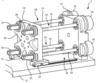
- FIG. 1 is a perspective view showing a mold clamping device according to an embodiment
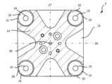
- FIG. FIG. 2 is a plan view of a movable platen according to the embodiment
- 1 is a front view of a mold clamping device according to an embodiment
- FIG. It is a top view of the movable platen which concerns on 2nd Embodiment. It is a top view of the movable board
- the mold clamping device is a fixed platen; a movable platen slidably provided with respect to the fixed platen; a plurality of sets of ball screw mechanisms that connect the fixed platen and the movable platen, The mold is opened and closed by driving the plurality of sets of ball screw mechanisms, Ribs are formed on the surface of the movable platen opposite to the surface facing the fixed platen.
- the injection molding machine is a mold clamping device for clamping the mold; and an injection device for injecting the injection material
- the mold clamping device includes a stationary platen, a movable platen slidably provided with respect to the fixed platen; a plurality of sets of ball screw mechanisms that connect the fixed platen and the movable platen, The mold is opened and closed by driving the plurality of sets of ball screw mechanisms, Ribs are formed on the surface of the movable platen opposite to the surface facing the fixed platen.
- An injection molding machine 1 according to the present embodiment comprises a mold clamping device 2 provided on a bed B and an injection device 4, as shown in FIG.
- the injection device 4 comprises a heating cylinder 6 , a screw 7 inserted in the heating cylinder 6 , and a screw driving device 8 for driving the screw 7 .
- the heating cylinder 6 is provided with a hopper 10 and an injection nozzle 11 at its tip.
- the injection material is fed from the hopper 10 and the screw 7 is rotated to melt the injection material, which is weighed at the tip of the screw 7 .
- the screw 7 is driven in the axial direction, the injection material is injected.
- the mold clamping device 2 consists of a so-called two-platen mold clamping device. That is, the mold clamping device 2 includes first and second mold plates 13 and 14, that is, a fixed platen 13 and a movable platen 14, as shown in FIG.
- the stationary platen 13 is fixed on the bed B, and the movable platen 14 is placed on linear guides 15, 15 provided on the bed B.
- the movable platen 14 is slidable in directions toward and away from the fixed platen 13 .
- a fixed side mold 16 is attached to the stationary platen 13, and a movable side mold 17 is attached to the movable platen 14, respectively.
- the number of ball screw mechanisms connecting the fixed platen and the movable platen is four.
- a fixed platen 13 and a movable platen 14 are connected by four sets of ball screw mechanisms 18, 18, .
- Each of the ball screw mechanisms 18, 18, . . . includes ball screws 19, 19, .
- the movable platen 14 has through holes, and ball nuts 20, 20, . . . are fixed to the through holes. That is, the ball screws 19, 19, . . . are connected to the movable platen 14 via ball nuts 20, 20, . On the other hand, the ball screws 19, 19, .
- the fixed platen 13 is provided with servo motors 22, 22, . . . which are connected to ball screws 19, 19, . Therefore, when the servomotors 22, 22, . . . are driven, the ball screws 19, 19, . That is, the molds 16 and 17 (see FIG. 1) are opened and closed.
- the mold clamping device 2 is characterized by the movable platen 14, and has a structure that achieves both weight reduction and rigidity.
- ribs 24 are formed on the movable platen 14 on the surface opposite to the surface facing the fixed platen 13 .
- FIG. 3 shows a plan view of the movable platen 14, and the movable platen 14 is formed in a substantially square shape. Ribs 24 are radially formed on the square so as to extend from the center 28 of the square toward the four sets of ball screw mechanisms 18, 18, . In this way, when the surface of the movable platen opposite to the surface facing the fixed platen is viewed in plan, the ribs are preferably formed radially from the center of the movable platen.
- a square has two line segments connecting the midpoints of opposite sides. That is, line segments 26 and 27 are shown.
- the rib 24 is formed symmetrically with respect to these two line segments 26 and 27 .
- rib 24 is rotated 90 degrees about center 28 of the square so that it overlaps rib 24 . That is, it has 90-degree rotational symmetry, that is, four-fold symmetry. Since the ribs 24 are formed symmetrically in this way, the force acting on the movable platen 14 is evenly distributed.
- the movable platen when the surface of the movable platen facing the fixed platen and the surface opposite to the fixed platen are viewed in plan, the movable platen is formed in a square shape, and the ribs are formed in four-fold symmetry with respect to the center of the square. It is one of preferred embodiments.
- the height of the ribs 24 is about 0.5 times the thickness of the movable platen 14 in this embodiment, it can be increased to 0.2 to 0.8 times.
- the ribs 24 are formed on the movable platen 14 according to the present embodiment, the rigidity of the movable platen 14 is sufficiently large and hardly deforms elastically. Therefore, in the mold clamping device 2 according to the present embodiment, no load is applied to the ball screw mechanisms 18, 18 due to the inclination of the ball nuts 20, 20. FIG. Furthermore, since the movable platen 14 is not elastically deformed, an effect of stabilizing mold clamping can be obtained. Since the ribs 24 provide the rigidity of the movable platen 14 according to the present embodiment, the movable platen 14 is formed with hollowed portions. Therefore, the movable platen 14 is lightened. When the movable platen 14 is driven by the servomotors 22, 22, . . . (see FIG. 2) and the ball screw mechanisms 18, 18, .
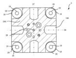
- FIG. 5 shows a movable platen 14A according to the second embodiment.
- the ribs 24A formed on the movable platen 14A according to this embodiment differ in shape from the ribs 24 of the movable platen 14 (see FIG. 3) according to the first embodiment. , and four-fold symmetry with respect to the center 28 .
- FIG. 6 shows a movable platen 14B according to the third embodiment. No rib 24B is formed near the center 28 of the square on this movable platen 14B. However, it is formed line-symmetrically with respect to the line segments 26 and 27 and has four-fold symmetry with respect to the center 28 .
- the second and third movable plates 14A and 14B shown in FIGS. 5 and 6 also have high rigidity due to the ribs 24A and 24B.
- FIG. 7 shows a movable platen 14C according to the fourth embodiment.
- the movable platen 14C is rectangular rather than square.
- a rib 24C formed on the movable platen 14C is also formed symmetrically with respect to the line segments 26 and 27.
- the movable platen 14C according to the fourth embodiment also has high rigidity. In this way, when the surface of the movable platen facing the fixed platen and the surface on the opposite side are viewed in plan, the movable platen is formed in a rectangular shape, and the ribs are line segments connecting the midpoints of the opposite sides of the rectangle. It is also a preferred aspect that the is formed line-symmetrically with respect to.
- the mold clamping device 2 (see FIG. 2) according to the present embodiment has four sets of ball screw mechanisms 18, 18, .
- the number of sets of the ball screw mechanisms 18, 18, . . . can be changed.
- two sets of ball screw mechanisms 18, 18 for connecting the fixed platen 13 and the movable platen 14 can be provided.
- FIG. 8 shows a part of a mold clamping device 2D provided with such two sets of ball screw mechanisms 18, 18, that is, a movable platen 14D according to the fifth embodiment.
- the two sets of ball screw mechanisms 18, 18 are arranged at two diagonal vertices among the four square vertexes when the movable platen 14D is viewed from above. In this embodiment, the other two vertices of the square are provided with guide rods 35,35.
- the rib 24D formed on the movable platen 14D according to the fifth embodiment has a shape extending from the vicinity of the center 28 of the square toward the two pairs of ball screw mechanisms 18, 18 located on the diagonal line.
- the rib 24D having such a shape can sufficiently prevent elastic deformation of the movable platen 14D, and can prevent the ball nuts 20, 20, . . . of the ball screw mechanisms 18, 18, .
- FIG. Although the guide rods 35, 35 are provided in this embodiment, the guide rods 35, 35 are not essential. This is because the two sets of ball screw mechanisms 18, 18 also allow the movable platen 14D to slide smoothly.
- injection molding machine 2 mold clamping device 4 injection device 6 heating cylinder 7 screw 8 screw driving device 10 hopper 11 injection nozzle 13 fixed platen 14 movable platen 15 linear guide 16 fixed side mold 17 movable side mold 18 ball screw mechanism 19 ball Screw 20 Ball nut 22 Servo motor 24 Rib 26, 27 Line segment 28 Center 30 Tensile force 31 Pushing force 33 Elastic deformation 35 Guide rod B Bed 2D Mold clamping device 14A, 14B, 14C, 14D Movable platen 24A, 24B, 24C, 24D rib
Landscapes
- Engineering & Computer Science (AREA)
- Manufacturing & Machinery (AREA)
- Mechanical Engineering (AREA)
- Moulds For Moulding Plastics Or The Like (AREA)
- Injection Moulding Of Plastics Or The Like (AREA)
Abstract
射出成形機(1)の型締装置(2)を、固定盤(13)と、この固定盤(13)に対してスライド自在に設けられている可動盤(14)と、これらを連結する複数組のボールねじ機構(18)と、を備えるようにする。本開示は可動盤(14)の、固定盤(13)に対向する面と反対側の面にリブ(24)を形成するようにする。
Description
本発明は、固定盤と可動盤とを備え、これらが複数組のボールねじ機構で連結されている型締装置、ならびに射出成形機に関するものである。
射出成形機もしくはプレス機には、金型を型締めする型締装置が設けられている。型締装置には色々な種類があるが、特許文献1にはいわゆる2プラテンからなる型締装置が記載されている。この型締装置は、固定盤と可動盤と、これら固定盤と可動盤とを連結する4組のボールねじ機構と、それぞれのボールねじ機構に設けられている4個のサーボモータとから構成されている。4個のサーボモータを駆動すると4組のボールねじ機構が駆動されて、可動盤が固定盤に対してスライドする。すなわち型開閉することになる。
特許文献1に記載の型締装置は、型盤が3個ではなく2個からなるので、型締装置をコンパクトに構成できる。したがって、比較的接地面積を小さくすることができるという優れた効果を奏する。しかしながら、解決すべき課題も見受けられる。具体的には、型締めするときに可動盤がわずかに弾性変形して、4組のボールねじ機構に負担がかかって劣化しやすいという問題である。詳しく説明すると、型締めするとき可動盤には4組のボールねじ機構から引張力が作用し、そして可動盤の中央に取り付けられている金型から押力が作用する。これらによって可動盤は弾性変形によりわずかに湾曲する。湾曲すると4組のボールねじ機構のボールナットが傾く。ボールねじに対してボールナットが傾いた状態でボールねじが回転すると負荷がかかって劣化しやすい。
可動盤の弾性変形を防止するために、可動盤の厚さを厚くして剛性を大きくすることもできる。しかしながら可動盤の重量が大きくなり型締装置が大型化してしまう。また重量が大きいと可動盤を駆動するサーボモータの負荷が大きくなり採用することはできない。
以上のような問題を鑑み、本開示において、十分な剛性を備えていながら可動盤の重量が小さい型締装置、および射出成形機を提供することを目的とする。
その他の課題と新規な特徴は、本明細書の記述及び添付図面から明らかになるであろう。
本開示は、固定盤と、この固定盤に対してスライド自在に設けられている可動盤と、これらを連結する複数組のボールねじ機構と、を備えた型締装置を対象とする。本発明者らは、可動盤の固定盤に対向する面と反対側の面にリブを形成することにより上記課題を解決できることを見出した。
本開示により、可動盤の剛性を大きく確保しながら重量を小さくすることができる型締装置および射出成形機を提供することができる。
以下、具体的な実施の形態について、図面を参照しながら詳細に説明する。ただし、以下の実施の形態に限定される訳ではない。説明を明確にするため、以下の記載及び図面は、適宜簡略化されている。各図面において、同一の要素には同一の符号が付されており、必要に応じて重複説明は省略されている。また、図面が煩雑にならないように、ハッチングが省略されている部分がある。
本実施の形態に係る型締装置は、
固定盤と、
該固定盤に対してスライド自在に設けられている可動盤と、
前記固定盤と前記可動盤とを連結する複数組のボールねじ機構と、を備え、
前記複数組のボールねじ機構を駆動すると型開閉するようになっており、
前記可動盤の前記固定盤に対向する面と反対側の面にはリブが形成されている。
固定盤と、
該固定盤に対してスライド自在に設けられている可動盤と、
前記固定盤と前記可動盤とを連結する複数組のボールねじ機構と、を備え、
前記複数組のボールねじ機構を駆動すると型開閉するようになっており、
前記可動盤の前記固定盤に対向する面と反対側の面にはリブが形成されている。
また、本実施の形態に係る射出成形機は、
金型を型締めする型締装置と、
射出材料を射出する射出装置とからなり、
前記型締装置は、固定盤と、
該固定盤に対してスライド自在に設けられている可動盤と、
前記固定盤と前記可動盤とを連結する複数組のボールねじ機構と、を備え、
前記複数組のボールねじ機構を駆動すると型開閉するようになっており、
前記可動盤の前記固定盤に対向する面と反対側の面にはリブが形成されている。
金型を型締めする型締装置と、
射出材料を射出する射出装置とからなり、
前記型締装置は、固定盤と、
該固定盤に対してスライド自在に設けられている可動盤と、
前記固定盤と前記可動盤とを連結する複数組のボールねじ機構と、を備え、
前記複数組のボールねじ機構を駆動すると型開閉するようになっており、
前記可動盤の前記固定盤に対向する面と反対側の面にはリブが形成されている。
<本実施の形態に係る射出成形機>
本実施の形態に係る射出成形機1は、図1に示されているように、ベッドBに設けられている型締装置2と、射出装置4とから構成されている。
本実施の形態に係る射出成形機1は、図1に示されているように、ベッドBに設けられている型締装置2と、射出装置4とから構成されている。
<射出装置>
射出装置4は加熱シリンダ6と、この加熱シリンダ6に入れられているスクリュ7と、スクリュ7を駆動するスクリュ駆動装置8とから構成されている。加熱シリンダ6にはホッパ10が設けられ、そして先端に射出ノズル11が設けられている。ホッパ10から射出材料が投入され、そしてスクリュ7を回転して射出材料を溶融するとスクリュ7の先端に計量される。スクリュ7を軸方向に駆動すると射出材料が射出されるようになっている。
射出装置4は加熱シリンダ6と、この加熱シリンダ6に入れられているスクリュ7と、スクリュ7を駆動するスクリュ駆動装置8とから構成されている。加熱シリンダ6にはホッパ10が設けられ、そして先端に射出ノズル11が設けられている。ホッパ10から射出材料が投入され、そしてスクリュ7を回転して射出材料を溶融するとスクリュ7の先端に計量される。スクリュ7を軸方向に駆動すると射出材料が射出されるようになっている。
<型締装置>
本実施の形態に係る型締装置2は、いわゆる2プラテンの型締装置からなる。すなわち型締装置2は、図2に示されているように、第1、2の型盤13、14、つまり固定盤13と可動盤14とを備えている。固定盤13はベッドB上に固定されており、可動盤14はベッドB上に設けられたリニアガイド15、15に載せられている。すなわち可動盤14は固定盤13に接近・離間する方向にスライド自在になっている。固定盤13には固定側金型16が、そして可動盤14には可動側金型17がそれぞれ取り付けられている。
本実施の形態に係る型締装置2は、いわゆる2プラテンの型締装置からなる。すなわち型締装置2は、図2に示されているように、第1、2の型盤13、14、つまり固定盤13と可動盤14とを備えている。固定盤13はベッドB上に固定されており、可動盤14はベッドB上に設けられたリニアガイド15、15に載せられている。すなわち可動盤14は固定盤13に接近・離間する方向にスライド自在になっている。固定盤13には固定側金型16が、そして可動盤14には可動側金型17がそれぞれ取り付けられている。
本実施の形態において、固定盤と可動盤とを連結するボールねじ機構は4組であることが好ましい。
本実施の形態に係る型締装置2は、固定盤13と可動盤14とが4組のボールねじ機構18、18、…によって連結されている。それぞれのボールねじ機構18、18、…は、ボールねじ19、19、…と、ボールねじ19、19、…が螺合するボールナット20、20、…とを備えている。
本実施の形態に係る型締装置2は、固定盤13と可動盤14とが4組のボールねじ機構18、18、…によって連結されている。それぞれのボールねじ機構18、18、…は、ボールねじ19、19、…と、ボールねじ19、19、…が螺合するボールナット20、20、…とを備えている。
図2には示されていないが、可動盤14には貫通孔が開けられており、この貫通孔にボールナット20、20、…が固着されている。つまりボールねじ19、19、…はボールナット20、20、…を介して可動盤14に接続されている。一方、ボールねじ19、19、…は、固定盤13を貫通し、固定盤13に対して回転可能に支持されている。固定盤13にはサーボモータ22、22、…が設けられ、ボールねじ19、19、…と接続されている。したがって、サーボモータ22、22、…を駆動するとボールねじ19、19、…が回転し、可動盤14がスライドすることになる。すなわち金型16、17(図1参照)が型開閉される。
<可動盤のリブ>
本実施の形態に係る型締装置2は、可動盤14に特徴があり、軽量化と剛性の確保とを両立させる構造になっている。具体的には、可動盤14には、固定盤13に対向する面と反対側の面において、リブ24が形成されている。図3には、可動盤14を平面視した様子が示されており、可動盤14は略正方形に形成されている。この正方形に対して、正方形の中心28から4組のボールねじ機構18、18、…に向かうように、リブ24が放射状に形成されている。
このように、可動盤の固定盤に対向する面と反対側の面を平面視したとき、リブは可動盤の中心から放射状に形成されていることが好ましい。
本実施の形態に係る型締装置2は、可動盤14に特徴があり、軽量化と剛性の確保とを両立させる構造になっている。具体的には、可動盤14には、固定盤13に対向する面と反対側の面において、リブ24が形成されている。図3には、可動盤14を平面視した様子が示されており、可動盤14は略正方形に形成されている。この正方形に対して、正方形の中心28から4組のボールねじ機構18、18、…に向かうように、リブ24が放射状に形成されている。
このように、可動盤の固定盤に対向する面と反対側の面を平面視したとき、リブは可動盤の中心から放射状に形成されていることが好ましい。
正方形には対辺の中点同士を結ぶ線分が2本存在する。すなわち線分26、27である。これら2本の線分26、27に対して、リブ24は線対称に形成されている。あるいは、リブ24を正方形の中心28を中心に90度回転させると、リブ24に重なる。つまり90度の回転対称つまり4回対称になっている。このようにリブ24は対称に形成されているので、可動盤14に作用する力が均一に分散することになる。すなわち、可動盤の固定盤に対向する面と反対側の面を平面視したとき、可動盤は正方形状に形成されており、リブは、前記正方形の中心に対して、4回対称に形成されていることが好ましい態様の一つである。
なお、可動盤14の厚さに対するリブ24の高さは、本実施の形態において約0.5倍になっているが、0.2~0.8倍等にすることができる。
なお、可動盤14の厚さに対するリブ24の高さは、本実施の形態において約0.5倍になっているが、0.2~0.8倍等にすることができる。
<リブの作用>
型締装置2において型締めをすると、図4に示されているように、可動盤14には複数の力が作用する。まず、4組のボールねじ機構18、18、によって引張力30、30が作用する。次いで金型17から押力31が作用する。引張力30、30は可動盤14の端部に作用し、押力31は可動盤14の中央に作用する。これらの力30、31は符号33で示されているように、可動盤14に対して弾性変形させるように作用する。このような弾性変形が生じてしまうと、可動盤14に固定されているボールナット20、20が傾き、ボールねじ機構18、18に大きな負荷が生じる。
型締装置2において型締めをすると、図4に示されているように、可動盤14には複数の力が作用する。まず、4組のボールねじ機構18、18、によって引張力30、30が作用する。次いで金型17から押力31が作用する。引張力30、30は可動盤14の端部に作用し、押力31は可動盤14の中央に作用する。これらの力30、31は符号33で示されているように、可動盤14に対して弾性変形させるように作用する。このような弾性変形が生じてしまうと、可動盤14に固定されているボールナット20、20が傾き、ボールねじ機構18、18に大きな負荷が生じる。
しかしながら、本実施の形態に係る可動盤14にはリブ24が形成されているので、可動盤14の剛性は十分に大きくほとんど弾性変形しない。したがって、本実施の形態に係る型締装置2において、ボールねじ機構18、18にはボールナット20、20の傾きに起因する負荷は発生しない。さらには、可動盤14が弾性変形しないので、型締めが安定する効果も得られる。このように本実施の形態に係る可動盤14の剛性はリブ24によって得られるようになっているので、可動盤14にはくり抜かれた部分が形成されている。したがって可動盤14は軽量化されている。サーボモータ22、22、…(図2参照)とボールねじ機構18、18、…とによって可動盤14を駆動するとき、駆動力は少なくて済むという効果も得られる。
<変形例>
本実施の形態は色々な変形が可能である。図5には第2の実施の形態に係る可動盤14Aが示されている。この実施の形態に係る可動盤14Aに形成されているリブ24Aは第1の実施の形態に係る可動盤14(図3参照)のリブ24と形状が相違しているが、線分26、27に対して線対称に形成され、中心28に対して4回対称になっている。図6には第3の実施の形態に係る可動盤14Bが示されている。この可動盤14Bにおいて正方形の中心28の近傍にはリブ24Bが形成されていない。しかしながら、線分26、27に対して線対称に形成され、中心28に対して4回対称になっている。図5、6に記載の第2、3の可動盤14A、14Bも、リブ24A、24Bによって高い剛性を備えている。
本実施の形態は色々な変形が可能である。図5には第2の実施の形態に係る可動盤14Aが示されている。この実施の形態に係る可動盤14Aに形成されているリブ24Aは第1の実施の形態に係る可動盤14(図3参照)のリブ24と形状が相違しているが、線分26、27に対して線対称に形成され、中心28に対して4回対称になっている。図6には第3の実施の形態に係る可動盤14Bが示されている。この可動盤14Bにおいて正方形の中心28の近傍にはリブ24Bが形成されていない。しかしながら、線分26、27に対して線対称に形成され、中心28に対して4回対称になっている。図5、6に記載の第2、3の可動盤14A、14Bも、リブ24A、24Bによって高い剛性を備えている。
図7には、第4の実施の形態に係る可動盤14Cが示されている。この可動盤14Cは正方形ではなく、長方形状を呈している。この可動盤14Cに形成されているリブ24Cも、線分26、27に対して線対称に形成されている。この第4の実施の形態に係る可動盤14Cも高い剛性を備えている。
このように、可動盤の固定盤に対向する面と反対側の面を平面視したとき、可動盤は長方形状に形成されており、リブは、前記長方形の対辺の中点同士を結ぶ線分に対して、線対称に形成されていることも好ましい態様である。
このように、可動盤の固定盤に対向する面と反対側の面を平面視したとき、可動盤は長方形状に形成されており、リブは、前記長方形の対辺の中点同士を結ぶ線分に対して、線対称に形成されていることも好ましい態様である。
本実施の形態に係る型締装置2(図2参照)は、固定盤13と可動盤14とを連結するボールねじ機構18、18、…は4組になっている。このボールねじ機構18、18、…の組数を変形することができる。例えば固定盤13と可動盤14とを連結するボールねじ機構18、18を2組とすることができる。図8には、このような2組のボールねじ機構18、18を備えた型締装置2Dの一部、つまり第5の実施の形態に係る可動盤14Dが示されている。2組のボールねじ機構18、18は、可動盤14Dを平面視したとき、正方形の4個の頂点のうち、対角の2個の頂点に配置されている。この実施の形態において、正方形の他の2個の頂点には、ガイドロッド35、35が設けられている。
第5の実施の形態に係る可動盤14Dに形成されているリブ24Dは、正方形の中心28近傍から、対角線上に位置する2組のボールねじ機構18、18に向かって伸びた形状になっている。このような形状のリブ24Dによって十分に可動盤14Dの弾性変形を防止することができ、ボールねじ機構18、18、…のボールナット20、20、…の傾きを防止できる。型締力を発生させるとき、可動盤14Dに対して2組のボールねじ機構18、18から引張力が作用するが、ガイドロッド35、35から引張力は作用しないからである。なお、この実施の形態にはガイドロッド35、35が設けられているが、ガイドロッド35、35は必須ではない。2組のボールねじ機構18、18によっても、可動盤14Dを滑らかにスライドさせることができるからである。
以上、本発明者によってなされた発明を実施の形態に基づき具体的に説明したが、本発明は既に述べた実施の形態に限定されるものではなく、その要旨を逸脱しない範囲において種々の変更が可能であることはいうまでもない。以上で説明した複数の例は、適宜組み合わせて実施されることもできる。
本開示によれば、可動盤の剛性を大きく確保しながら重量を小さくすることができる型締装置および射出成形機を提供することができる。
本発明を詳細にまた特定の実施態様を参照して説明したが、本発明の精神と範囲を逸脱することなく様々な変更や修正を加えることができることは当業者にとって明らかである。
本出願は、2021年11月25日出願の日本特許出願(特願2021-190714)に基づくものであり、その内容はここに参照として取り込まれる。
本出願は、2021年11月25日出願の日本特許出願(特願2021-190714)に基づくものであり、その内容はここに参照として取り込まれる。
1 射出成形機 2 型締装置
4 射出装置 6 加熱シリンダ
7 スクリュ 8 スクリュ駆動装置
10 ホッパ 11 射出ノズル
13 固定盤 14 可動盤
15 リニアガイド 16 固定側金型
17 可動側金型 18 ボールねじ機構
19 ボールねじ 20 ボールナット
22 サーボモータ 24 リブ
26、27 線分 28 中心
30 引張力 31 押力
33 弾性変形 35 ガイドロッド
B ベッド 2D 型締装置
14A、14B、14C、14D 可動盤
24A、24B、24C、24D リブ
4 射出装置 6 加熱シリンダ
7 スクリュ 8 スクリュ駆動装置
10 ホッパ 11 射出ノズル
13 固定盤 14 可動盤
15 リニアガイド 16 固定側金型
17 可動側金型 18 ボールねじ機構
19 ボールねじ 20 ボールナット
22 サーボモータ 24 リブ
26、27 線分 28 中心
30 引張力 31 押力
33 弾性変形 35 ガイドロッド
B ベッド 2D 型締装置
14A、14B、14C、14D 可動盤
24A、24B、24C、24D リブ
Claims (10)
- 固定盤と、
該固定盤に対してスライド自在に設けられている可動盤と、
前記固定盤と前記可動盤とを連結する複数組のボールねじ機構と、を備え、
前記複数組のボールねじ機構を駆動すると型開閉するようになっており、
前記可動盤の前記固定盤に対向する面と反対側の面にはリブが形成されている、型締装置。 - 前記固定盤と前記可動盤とを連結する前記ボールねじ機構は4組である、請求項1に記載の型締装置。
- 前記反対側の面を平面視したとき、前記可動盤は長方形状に形成されており、前記リブは、前記長方形の対辺の中点同士を結ぶ線分に対して、線対称に形成されている、請求項1または2に記載の型締装置。
- 前記反対側の面を平面視したとき、前記可動盤は正方形状に形成されており、前記リブは、前記正方形の中心に対して、4回対称に形成されている、請求項1または2に記載の型締装置。
- 前記反対側の面を平面視したとき、前記リブは前記可動盤の中心から放射状に形成されている、請求項1~4のいずれかの項に記載の型締装置。
- 金型を型締めする型締装置と、
射出材料を射出する射出装置とからなり、
前記型締装置は、固定盤と、
該固定盤に対してスライド自在に設けられている可動盤と、
前記固定盤と前記可動盤とを連結する複数組のボールねじ機構と、を備え、
前記複数組のボールねじ機構を駆動すると型開閉するようになっており、
前記可動盤の前記固定盤に対向する面と反対側の面にはリブが形成されている、射出成形機。 - 前記固定盤と前記可動盤とを連結する前記ボールねじ機構は4組である、請求項6に記載の射出成形機。
- 前記反対側の面を平面視したとき、前記可動盤は長方形状に形成されており、前記リブは、前記長方形の対辺の中点同士を結ぶ線分に対して、線対称に形成されている、請求項6または7に記載の射出成形機。
- 前記反対側の面を平面視したとき、前記可動盤は正方形状に形成されており、前記リブは、前記正方形の中心に対して、4回対称に形成されている、請求項6または7に記載の射出成形機。
- 前記反対側の面を平面視したとき、前記リブは前記可動盤の中心から放射状に形成されている、請求項6~9のいずれかの項に記載の射出成形機。
Applications Claiming Priority (2)
| Application Number | Priority Date | Filing Date | Title |
|---|---|---|---|
| JP2021190714A JP7576018B2 (ja) | 2021-11-25 | 2021-11-25 | 型締装置、および射出成形機 |
| JP2021-190714 | 2021-11-25 |
Publications (1)
| Publication Number | Publication Date |
|---|---|
| WO2023095433A1 true WO2023095433A1 (ja) | 2023-06-01 |
Family
ID=86539198
Family Applications (1)
| Application Number | Title | Priority Date | Filing Date |
|---|---|---|---|
| PCT/JP2022/035539 Ceased WO2023095433A1 (ja) | 2021-11-25 | 2022-09-22 | 型締装置、および射出成形機 |
Country Status (2)
| Country | Link |
|---|---|
| JP (1) | JP7576018B2 (ja) |
| WO (1) | WO2023095433A1 (ja) |
Citations (2)
| Publication number | Priority date | Publication date | Assignee | Title |
|---|---|---|---|---|
| JPH0420422Y2 (ja) * | 1990-10-06 | 1992-05-11 | ||
| JP2009066774A (ja) * | 2007-09-10 | 2009-04-02 | Mitsubishi Heavy Industries Plastic Technology Co Ltd | 型盤、型締め装置、射出成形機 |
Family Cites Families (4)
| Publication number | Priority date | Publication date | Assignee | Title |
|---|---|---|---|---|
| JPH0611157Y2 (ja) * | 1990-06-08 | 1994-03-23 | 株式会社新潟鐵工所 | 射出成形機における可動盤 |
| US6439876B1 (en) | 2000-10-30 | 2002-08-27 | Husky Injection Molding Systems, Ltd. | Injection molding machine having a platen for uniform distribution of clamping forces |
| JP5456289B2 (ja) | 2008-09-09 | 2014-03-26 | 住友重機械工業株式会社 | 型締装置及び可動プラテン |
| JP6727875B2 (ja) | 2016-03-25 | 2020-07-22 | 住友重機械工業株式会社 | 射出成形機 |
-
2021
- 2021-11-25 JP JP2021190714A patent/JP7576018B2/ja active Active
-
2022
- 2022-09-22 WO PCT/JP2022/035539 patent/WO2023095433A1/ja not_active Ceased
Patent Citations (2)
| Publication number | Priority date | Publication date | Assignee | Title |
|---|---|---|---|---|
| JPH0420422Y2 (ja) * | 1990-10-06 | 1992-05-11 | ||
| JP2009066774A (ja) * | 2007-09-10 | 2009-04-02 | Mitsubishi Heavy Industries Plastic Technology Co Ltd | 型盤、型締め装置、射出成形機 |
Also Published As
| Publication number | Publication date |
|---|---|
| JP2023077461A (ja) | 2023-06-06 |
| JP7576018B2 (ja) | 2024-10-30 |
Similar Documents
| Publication | Publication Date | Title |
|---|---|---|
| CN105328883B (zh) | 合模机构 | |
| CN110062688B (zh) | 压板、合模装置、注射成形机 | |
| CN103213240B (zh) | 具有模具安装位置调整机构的注塑成型机 | |
| US5123834A (en) | Mold support platen structure | |
| JP2010111018A (ja) | 型締装置 | |
| US7351055B2 (en) | Injection molding machine | |
| CN101386204A (zh) | 压模台板、合模装置及注射成型机 | |
| JP3792663B2 (ja) | 成形機の型締機構 | |
| JP2010241076A (ja) | ノズルタッチ機構部を備えた射出成形機 | |
| WO2023095433A1 (ja) | 型締装置、および射出成形機 | |
| US20070077329A1 (en) | Injection molding machine | |
| JP5456289B2 (ja) | 型締装置及び可動プラテン | |
| JP2008162103A (ja) | 型締装置と、この型締装置を備えた射出成形機 | |
| JP6756795B2 (ja) | 射出成形機の型締装置 | |
| CN104070645A (zh) | 注射成型机 | |
| JP2024002362A (ja) | 型締装置および射出成形機 | |
| JP2022178772A (ja) | 2台の射出装置を備えたツイン射出成形機 | |
| JP2001239561A (ja) | 射出成形機 | |
| TWI729677B (zh) | 樹脂成形裝置以及樹脂成形品的製造方法 | |
| WO2023120278A1 (ja) | 樹脂封止装置 | |
| JP7603364B2 (ja) | ボールねじ機構、型締装置、および射出成形機 | |
| JP2020124891A (ja) | 射出成形機のエジェクタ機構 | |
| WO2026058423A1 (ja) | プラテン、型締装置および射出成形機 | |
| KR102251065B1 (ko) | 수지 성형 장치 및 수지 성형품의 제조 방법 | |
| EP2796267A2 (en) | Injection molding machine |
Legal Events
| Date | Code | Title | Description |
|---|---|---|---|
| 121 | Ep: the epo has been informed by wipo that ep was designated in this application |
Ref document number: 22898218 Country of ref document: EP Kind code of ref document: A1 |
|
| NENP | Non-entry into the national phase |
Ref country code: DE |
|
| 122 | Ep: pct application non-entry in european phase |
Ref document number: 22898218 Country of ref document: EP Kind code of ref document: A1 |