WO2023095407A1 - 制御装置、及びこれの制御方法、電動パワーステアリング装置 - Google Patents
制御装置、及びこれの制御方法、電動パワーステアリング装置 Download PDFInfo
- Publication number
- WO2023095407A1 WO2023095407A1 PCT/JP2022/032524 JP2022032524W WO2023095407A1 WO 2023095407 A1 WO2023095407 A1 WO 2023095407A1 JP 2022032524 W JP2022032524 W JP 2022032524W WO 2023095407 A1 WO2023095407 A1 WO 2023095407A1
- Authority
- WO
- WIPO (PCT)
- Prior art keywords
- steering
- steering wheel
- angle
- torque
- correction
- Prior art date
- Legal status (The legal status is an assumption and is not a legal conclusion. Google has not performed a legal analysis and makes no representation as to the accuracy of the status listed.)
- Ceased
Links
Images


Classifications
-
- B—PERFORMING OPERATIONS; TRANSPORTING
- B62—LAND VEHICLES FOR TRAVELLING OTHERWISE THAN ON RAILS
- B62D—MOTOR VEHICLES; TRAILERS
- B62D6/00—Arrangements for automatically controlling steering depending on driving conditions sensed and responded to, e.g. control circuits
-
- B—PERFORMING OPERATIONS; TRANSPORTING
- B62—LAND VEHICLES FOR TRAVELLING OTHERWISE THAN ON RAILS
- B62D—MOTOR VEHICLES; TRAILERS
- B62D5/00—Power-assisted or power-driven steering
- B62D5/04—Power-assisted or power-driven steering electrical, e.g. using an electric servo-motor connected to, or forming part of, the steering gear
- B62D5/0457—Power-assisted or power-driven steering electrical, e.g. using an electric servo-motor connected to, or forming part of, the steering gear characterised by control features of the drive means as such
- B62D5/046—Controlling the motor
- B62D5/0463—Controlling the motor calculating assisting torque from the motor based on driver input
-
- B—PERFORMING OPERATIONS; TRANSPORTING
- B62—LAND VEHICLES FOR TRAVELLING OTHERWISE THAN ON RAILS
- B62D—MOTOR VEHICLES; TRAILERS
- B62D5/00—Power-assisted or power-driven steering
- B62D5/04—Power-assisted or power-driven steering electrical, e.g. using an electric servo-motor connected to, or forming part of, the steering gear
-
- B—PERFORMING OPERATIONS; TRANSPORTING
- B62—LAND VEHICLES FOR TRAVELLING OTHERWISE THAN ON RAILS
- B62D—MOTOR VEHICLES; TRAILERS
- B62D6/00—Arrangements for automatically controlling steering depending on driving conditions sensed and responded to, e.g. control circuits
- B62D6/008—Control of feed-back to the steering input member, e.g. simulating road feel in steer-by-wire applications
Definitions
- the present invention relates to a steering device mounted on an automobile, and more particularly to an electric power steering device that performs steering control using an electric motor.
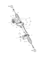
- FIG. 1 is a perspective view showing an appearance of an electric power steering device
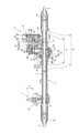
- FIG. 2 is a sectional view showing a vertical section of the electric power steering device shown in FIG. 1
- FIG. 2 is a control block diagram showing the configuration of a controller used in the electric power steering system
- FIG. 4 is a block diagram showing control blocks for determining an assist force (assist torque) according to the embodiment of the present invention
- FIG. 5 is an explanatory diagram for explaining a torque-corrected steering wheel angle obtained by a torque-corrected steering wheel angle calculation block shown in FIG. 4
- 5 is a block diagram showing a specific control block of the proportional/integral control processing block shown in FIG. 4
- FIG. 4 is a flow chart showing a control flow for realizing a function of a control block for obtaining correction torque
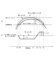
- FIG. 7 is an explanatory diagram for explaining a torque correction steering wheel angle obtained by the processing flow.
- FIG. 1 and 2 show the rotation angle, rotation direction, and rotation angle of the steering shaft separately from the drive (manual steering force) of the steering shaft (hereinafter referred to as rack bar) by the steering shaft rotated by the steering wheel.
- Rotating torque is detected, an electric motor (corresponding to a steering actuator in claims) is rotated based on these detection signals (corresponding to steering information in claims), and the rotation of the electric motor is transmitted to the nut.
- This shows an electric power steering device that assists steering force by driving a rack bar housed in a nut.
- the steering mechanism 1 includes a steering shaft 4 connected to a steering wheel (not shown) arranged in the cab of the vehicle, a rack bar 5 as a steering shaft linked to the steering wheel, the steering shaft 4 and the rack bar. and a conversion mechanism 6 for linking with 5.
- the conversion mechanism 6 is a so-called rack and pinion mechanism composed of pinion teeth (not shown) formed on the outer circumference of the steering shaft 4 and rack teeth (not shown) formed on the outer circumference of the rack bar 5. is.
- Both ends of the rack bar 5 in the axial direction are linked to a pair of steering wheels via tie rods 9 and a pair of knuckle arms.
- tie rods 9 and a pair of knuckle arms are linked to a pair of steering wheels via tie rods 9 and a pair of knuckle arms.
- the rack bar accommodating portion 11 includes a first rack bar accommodating portion 14 that axially penetrates the interior of the first housing 12 and a second rack bar accommodating portion 15 that axially penetrates the interior of the second housing 13 .
- bellows-shaped boots 16 are mounted across the tie rods 9 .
- These boots 16 are made of an elastic material such as a synthetic rubber material so as to ensure a predetermined flexibility and prevent water, dust, etc. from entering the interior of the housing 3 .
- a steering angle sensor 20 that detects a steering angle (corresponding to a steering wheel angle, which will be described later), which is the amount of rotation of the steering wheel from a neutral steering angle
- a torque sensor that detects torque input to the steering shaft 4. 21 are accommodated in a sensor housing 22 which is part of the housing 3 formed so as to surround the outer circumference of the steering shaft 4 together.
- the stator 26 is constructed by winding U-phase, V-phase, and W-phase coils around a stator core (not shown) formed by laminating a plurality of thin plates.
- the coils are connected by so-called Y connection (star connection), but they may be connected by delta connection.
- the motor shaft 28 has a first ball bearing 29 provided between the outer peripheral surface of the one end portion 28a side and the inner peripheral surface of the through hole of the first end wall portion 23b, and the outer peripheral surface of the other end portion 28b side. and the second ball bearing 30 provided between the second end wall portion 23c and the inner peripheral surface of the through hole of the second end wall portion 23c.
- the transmission mechanism accommodating portion 31 includes a first transmission mechanism accommodating portion 36 provided at the end of the first rack bar accommodating portion 14 on the second housing 13 side, and a second rack bar accommodating portion 15 on the first housing 12 side. It is formed by joining the second transmission mechanism housing portion 37 provided at the end portion.
- the belt 34 is an endless belt in which a core material such as glass fiber or steel wire is embedded. is transmitted to the output side pulley 33 .
- the nut 38 is rotatably supported via a ball bearing 41 housed inside the first transmission mechanism housing portion 36 .
- the ball bearing 41 includes an inner race portion 41a integrally formed with the nut 38, an outer race portion 41b fixed to the inner peripheral surface of the first transmission mechanism accommodating portion 36, and a space between the inner race portion 41a and the outer race portion 41b. and a plurality of balls 41c housed in a rollable manner.
- the inner race portion 41a and the nut 38 are integrally formed in this embodiment, the inner race portion 41a and the nut 38 may be formed separately.
- the control housing 42 has a tubular body 45 whose one end on the electric motor 17 side covers the outer circumference of the motor housing 23 and a cover 46 that closes the opening on the other end side of the body 45 .
- the control board 44 is made of a non-conductive resin material such as glass epoxy resin, and has conductor patterns formed on both sides thereof. It is composed of
- This motor rotation angle sensor detects the rotation angle of the motor shaft 28 (rotor 27) based on changes in the magnetic field generated by a magnet (not shown) attached to the other end 28b of the motor shaft 28. Further, the motor rotation angle sensor has a dual system of main and sub motor rotation angle detection units, each of which detects the rotation angle of the motor shaft 28 .
- FIG. 3 shows the hardware configuration of the controller 19 of FIG.
- the controller 19 includes a control micro control unit (control MCU) 51, a monitoring micro control unit (monitoring MCU) 52, a MOSFET pre-driver circuit 53, and an inverter which is a motor drive circuit. It includes a drive circuit 54, a current detection circuit 55, a rotation angle detection circuit 56, and the like.
- the ROM 58 stores various programs executed by the CPU 57. Specifically, the ROM 58 stores a control program for executing motor control processing (steering processing) for controlling the electric motor 17 . Further, the ROM 58 stores a diagnostic program for diagnosing the power steering system. The control program and diagnostic program are for executing predetermined control functions and diagnostic functions by means of the CPU 57 .
- the inverter drive circuit 54 is an inverter drive circuit that includes a bridge circuit consisting of a pair of MOSFET switching elements for three phases, one for the U phase, one for the V phase, and one for the W phase. It is connected.
- the DC voltage applied to the inverter drive circuit 54 is converted into a three-phase AC voltage by the switching operation of the MOSFET switching elements in the inverter drive circuit 54, thereby driving the electric motor 17.
- Shunt resistors R1 and R2 are connected to the bridge circuit.
- a current detection circuit 55 is connected to the shunt resistors R1 and R2 to detect current information of the electric motor 17 and output it to the A/D converter 61 . Further, the rotation angle detection circuit 56 outputs an output signal from a motor rotation angle sensor 66 that detects the rotation angle of the rotor of the electric motor 17 to the A/D converter 61 as motor rotation angle information. ing.
- the motor rotation angle sensor 66 has a dual system of main and sub motor rotation angle detection units, each of which detects the rotation angle of the motor shaft 28 .
- the monitoring microcontrol unit 52 includes a CPU, ROM, RAM, D/A converter, A/D converter, interface, etc., as is well known. It monitors runaway of the CPU 57 of the micro control unit 51 for control.
- the angle difference between the torque correction steering wheel angle arbitrarily set based on the actual steering wheel angle and the actual steering wheel angle is obtained, and this angle difference is used for negative correction torque, and a positive correction torque, and the assist torque is corrected by the calculated correction torque.
- the negative correction torque has a component that reduces the torque that urges the rack bar toward the stroke end
- the positive correction torque has a component that increases the torque that urges the rack bar toward the stroke end.
- the configuration is such that the assist torque is corrected by the calculated correction torque. Therefore, it is possible to suppress the impact sound due to the collision and the unintended rotation of the steering wheel due to the rebound after the collision with a simple control logic without newly installing another detection sensor.
- the torque correction function unit 71 includes a torque correction steering wheel angle calculation processing block 72 that calculates a torque correction steering wheel angle ( ⁇ com) generated based on the actual steering wheel angle ( ⁇ act), and a torque correction steering wheel angle calculation block 72 that calculates the actual steering wheel angle ( ⁇ act) and the torque correction steering wheel angle ( .theta.com) by performing proportional/integral control on the deviation (angle difference) to obtain the correction torque, and an addition block 74 for adding the obtained correction torque to the normal assist torque. .
- a negative correction torque and a positive correction torque are generated.
- a negative correction torque reduces the normal assist torque, and a positive correction torque increases the normal assist torque to obtain the total assist torque. That is, the negative correction torque acts to reduce the rack axial force, and the positive correction torque acts to increase the rack axial force.
- the normal assist torque is reduced by the negative correction torque to suppress the impact noise caused by the collision.
- the normal assist torque is increased by the positive correction torque to suppress the rebound of the rack bar 5 and suppress unintended rotation of the steering wheel.
- the angle difference ( ⁇ ) is a constant value as shown in FIG.
- the transition section between the first torque correction steering wheel angle ( ⁇ com1) and the second torque correction steering wheel angle ( ⁇ com2) is the torque correction steering wheel angle ( ⁇ com) before the transition starts. is used continuously.
- the proportional component of the obtained angular difference is obtained by the proportional control unit 76 of the proportional/integral control processing block 73, and the integral component is similarly obtained by the integral control unit 77.
- These proportional component and integral component are added by the adder 78 and output as a correction torque. Furthermore, as shown in FIG. 4, this correction torque is added to the normal assist torque and applied to the electric motor as a total assist torque.
- step S10 it is determined whether or not the actual steering wheel angle ( ⁇ act) is greater than the control start angle ( ⁇ srt). This determination determines whether or not the steering wheel is rotated to move the rack bar 5 toward the stroke end side.
- control start angle ( ⁇ srt) can be changed according to the specifications of the automobile, and the most suitable control start angle ( ⁇ srt) should be set.
- the control start angle ( ⁇ srt) can also be changed based on the angular velocity of the steering wheel operation rotation angle. When the steering wheel is rotated quickly, the rack bar 5 may quickly hit the structural member (stopper mechanism) at the stroke end. In this case, the control start angle ( ⁇ srt) should be shifted toward the neutral position as the operation angular velocity increases.
- step S11 when the torque correction steering wheel angle previous value ( ⁇ prv) is set, the process exits to return and waits for the next execution timing.
- step S10 it is determined that the actual steering wheel angle ( ⁇ act) is greater than the control start angle ( ⁇ srt) (YES), so the steering wheel is largely rotated. For example, rotation of the steering wheel for "stationary steering” and rotation of the steering wheel for “turning back” correspond to this. In this case, a phenomenon often occurs in which the rack bar 5 collides with the structural member (stopper mechanism) at the stroke end.
- the reason why it is determined (NO) that the torque correction steering wheel angle previous value ( ⁇ prv) is larger than the first torque correction steering wheel angle ( ⁇ com1) is the control start angle ( ⁇ srt) set in step S11. This is because the torque correction steering wheel angle previous value ( ⁇ prv) is larger than the first torque correction steering wheel angle ( ⁇ com1) obtained by subtracting the correction angle ( ⁇ ) from the actual steering wheel angle ( ⁇ act).
- step S13 Since it is determined in step S12 that the previous torque correction steering wheel angle value ( ⁇ prv) is larger than the first torque correction steering wheel angle ( ⁇ com1) (NO), in step S13 the previous torque correction steering wheel angle value ( ⁇ prv) is , is larger than the second torque correction steering wheel angle ( ⁇ com2). If it is determined (NO) that the torque correction steering wheel angle previous value ( ⁇ prv) is smaller than the second torque correction steering wheel angle ( ⁇ com2), the process proceeds to step S14. On the other hand, if it is determined that the torque correction steering wheel angle previous value ( ⁇ prv) is larger than the second torque correction steering wheel angle ( ⁇ com1) (YES), the process proceeds to step S16.
- the reason why it is determined (NO) that the torque correction steering wheel angle previous value ( ⁇ prv) is smaller than the second torque correction steering wheel angle ( ⁇ com2) is the control start angle ( ⁇ srt) set in step S11. This is because the torque correction steering wheel angle previous value ( ⁇ prv) is smaller than the second torque correction steering wheel angle ( ⁇ com2) obtained by adding the correction angle ( ⁇ ) to the actual steering wheel angle ( ⁇ act).
- the torque correction steering wheel angle previous value ( ⁇ prv) is the control start angle ( ⁇ srt).
- the torque correction steering wheel angle ( ⁇ com) is set as shown at time (Ta) to time (Tb) in FIG. 8(a). Further, the angle difference between the actual steering wheel angle ( ⁇ act) and the torque correction steering wheel angle ( ⁇ com) at this time is on the negative side between time (Ta) and time (Tb) as shown in FIG. 8(b). It will gradually grow.
- step S17 When the torque correction steering wheel angle ( ⁇ com) is set, the process proceeds to step S17. Since step S17 and subsequent steps are proportional/integral control, this will be described later.
- step S15 In executing step S15, in step S12, it is determined that the torque correction steering wheel angle previous value ( ⁇ prv) is smaller than the first torque correction steering wheel angle ( ⁇ com1) (YES).
- the reason why it is determined (YES) that the torque correction steering wheel angle previous value ( ⁇ prv) is smaller than the first torque correction steering wheel angle ( ⁇ com1) is as follows.
- step S15 the torque correction steering wheel angle ( ⁇ com) is set to the first torque correction steering wheel angle ( ⁇ com1). Also, this first torque correction steering wheel angle ( ⁇ com1) becomes the torque correction steering wheel angle previous value ( ⁇ prv) at the next execution timing.
- step S12 determines (NO) in step S12 that the torque correction steering wheel angle previous value ( ⁇ prv) is greater than the first torque correction steering wheel angle ( ⁇ com1), the torque correction steering wheel angle ( ⁇ com) is It is set to the steering wheel angle ( ⁇ com1).
- the first torque correction steering wheel angle ( ⁇ com1) is set as shown from time (Tb) to time (Tc) in FIG. 8(a).
- Time (Tb) to time (Tc) is a section until the rack bar 5 contacts the structural material (stopper mechanism) at the stroke end, and this section is a negative correction torque (a torque that reduces the assist torque).
- the angle difference between the actual steering wheel angle ( ⁇ act) and the first torque correction steering wheel angle ( ⁇ com1) at this time becomes negative between time (Tb) and time (Tc) as shown in FIG. 8(b).
- a constant correction angle ( ⁇ ) is maintained on the side.
- the torque correction steering wheel angle ( ⁇ com) is set as shown at time (Tc) to time (Te) in FIG. 8(a). be. Further, the angle difference between the actual steering wheel angle ( ⁇ act) and the torque corrected steering wheel angle ( ⁇ com) at this time is on the positive side between time (Tc) and time (Td) as shown in FIG. 8(b). It gradually decreases toward the time, and further increases gradually on the positive side from time (Td) to time (Te).
- step S17 Since step S17 and subsequent steps are proportional/integral control, this will be described later.
- the previous torque correction steering wheel angle value ( ⁇ prv) set in step S15 is the first torque correction steering wheel angle ( ⁇ com1).
- the actual steering wheel angle ( ⁇ act) decreases with the passage of time (the steering wheel reversely rotates due to the bouncing of the rack bar), and accordingly the second torque correction steering wheel angle ( ⁇ com2) also decreases. is.
- the previous torque-corrected steering wheel angle value ( ⁇ prv) becomes larger than the second torque-corrected steering wheel angle ( ⁇ com2), and as a result, the process proceeds to step S16.
- step S13 the torque-corrected steering wheel angle previous value ( ⁇ prv) is smaller than the second torque-corrected steering wheel angle ( ⁇ com2), the torque-corrected steering wheel angle ( ⁇ com) remains unchanged from the second torque-corrected steering wheel angle ( ⁇ com2). It is set to the steering wheel angle ( ⁇ com2).
- step S10 when the actual steering wheel angle ( ⁇ act) returns to the control start angle ( ⁇ srt), the correction of the normal assist torque using the correction torque described above ends in step S10.
- step S17 When the second torque correction steering wheel angle ( ⁇ com2) is set, the process proceeds to step S17. Since step S17 and subsequent steps are proportional/integral control, this will be described later.
- step S18 an operation is performed to obtain a proportional component and an integral component based on the angular difference obtained in step S17.
- the calculation of this proportional component and integral component is a well-known technique.
- the process proceeds to step S19.
- step S19 the correction torque is calculated by adding the proportional component and the integral component.
- this correction torque as described above, a negative correction torque and a positive correction torque are obtained from the negative angle difference and the positive angle difference.
- the calculated correction torque is added to the normal assist torque to obtain the total assist torque, as shown in FIG. This total assist torque is applied to the electric motor as drive current to assist steering.
- the absolute value of the correction angle (- ⁇ ) set on the neutral position side of the actual steering wheel angle ( ⁇ act) and the correction angle (+ ⁇ ) set on the stroke end side of the actual steering wheel angle ( ⁇ act) values are assumed to be the same.
- the correction angle (- ⁇ ) set on the neutral position side may be set larger than the correction angle (+ ⁇ ) set on the stroke end side. If the correction angle (- ⁇ ) set on the neutral position side is set large in this way, the assist torque in the direction of the stroke end can be reduced, so the rebound of the rack bar itself is suppressed.
- the correction angle (+ ⁇ ) set on the stroke end side may be set larger than the correction angle ( ⁇ ) set on the neutral position side. If the correction angle (+.DELTA..theta.) set on the stroke end side is set large in this manner, the rebound of the rack bar is further suppressed. As a result, the return of the handle due to bounce can be further suppressed.
- an electric power steering system has been described in which the steering actuator applies assist torque to the steering member.
- this technology separates the steering shaft from the rack bar, detects the rotation angle, rotation direction, rotation torque, etc. of the steering shaft, and controls the rotation of the electric motor based on these detection signals to control the rack bar. can be applied to a so-called steer-by-wire type electric power steering device that directly drives the .
- a control device is a vehicle that includes a steering wheel for steering a vehicle, a steering member that steers the steered wheels according to rotation of the steering wheel, and a steering actuator that applies a steering force to the steering member. and includes a control unit for outputting a drive signal for applying a steering force to the steering actuator based on the steering information of the steering wheel, and when the rotation angle of the steering wheel reaches a predetermined control start angle, A drive signal is output to the steering actuator to reduce the steering force until the steering member reaches the stroke end, and to increase the steering force when the steering member reaches the stroke end and bounces back.
- the present invention is not limited to the above-described embodiment, and includes various modifications.
- the above-described embodiments have been described in detail in order to explain the present invention in an easy-to-understand manner, and are not necessarily limited to those having all the configurations described.
- part of the configuration of one embodiment can be replaced with the configuration of another embodiment, and the configuration of another embodiment can be added to the configuration of one embodiment.
Landscapes
- Engineering & Computer Science (AREA)
- Chemical & Material Sciences (AREA)
- Combustion & Propulsion (AREA)
- Transportation (AREA)
- Mechanical Engineering (AREA)
- Power Steering Mechanism (AREA)
- Steering Control In Accordance With Driving Conditions (AREA)
Abstract
Description
変換機構6は、ステアリングシャフト4の外周に形成されたピニオン歯(図示せず)と、ラックバー5の外周に形成されたラック歯(図示せず)とにより構成される、いわゆるラック・ピニオン機構である。
このモータ回転角センサ66は、メイン、サブの二重系のモータ回転角検出部を有しており、その各々がモータ軸28の回転角を検出するようになっている。
ステップS10においては、実ハンドル角(θact)が制御開始角(θsrt)より大きいか否かを判断している。この判断は、ステアリングホイールを回転させてラックバー5をストロークエンドの側に向けて移動させる状態に入ったかどうかを判断している。
ステップS10で、実ハンドル角(θact)が制御開始角(θsrt)より小さいと判断されているので、ステップS11においては、トルク補正ハンドル角を制御開始角(θsrt)に設定する。この制御開始角(θsrt)は、ステップS10の判断で、実ハンドル角(θact)が制御開始角(θsrt)より大きいと判断されている場合の制御で必要とされる、トルク補正ハンドル角前回値(θprv)とするためである。
ステップS10で、実ハンドル角(θact)が制御開始角(θsrt)より大きい(YES)と判断されているので、ステアリングホールが大きく回転されている状態である。
例えば「据え切り」のためのステアリングホイールの回転や、「切り返し」のためのステアリングホイールの回転等がこれに対応する。この場合、ラックバー5がストロークエンドの構造材(ストッパ機構)に衝突する現象が往々にして発生する。
ステップS12で、トルク補正ハンドル角前回値(θprv)が、第1トルク補正ハンドル角(θcom1)より大きい(NO)と判断されているので、ステップS13では、トルク補正ハンドル角前回値(θprv)が、第2トルク補正ハンドル角(θcom2)より大きいかどうかを判断している。この判断で、トルク補正ハンドル角前回値(θprv)が、第2トルク補正ハンドル角(θcom2)より小さい(NO)と判断されるとステップS14に移行する。一方、トルク補正ハンドル角前回値(θprv)が、第2トルク補正ハンドル角(θcom1)より大きい(YES)と判断されるとステップS16に移行する。
ステップS12、ステップS13で「No」判断される、つまり、トルク補正ハンドル角前回値(θprv)が、第1トルク補正ハンドル角(θcom1)と第2トルク補正ハンドル角(θcom2)の間に位置していると、ステップS14においては、トルク補正ハンドル角(θcom)を、トルク補正ハンドル角前回値(θprv)に設定する。ここで、トルク補正ハンドル角前回値(θprv)は、制御開始角(θsrt)である。
ステップS15を実行するにあたり、ステップS12においては、トルク補正ハンドル角前回値(θprv)が、第1トルク補正ハンドル角(θcom1)より小さい(YES)と判断されている。ここで、トルク補正ハンドル角前回値(θprv)が、第1トルク補正ハンドル角(θcom1)より小さい(YES)と判断される理由は以下の通りである。
先のステップS15では、ラックバー5がストロークエンドの構造材(ストッパ機構)に接触するまで第1トルク補正ハンドル角(θcom1)を設定するものであるが、ラックバー5がストロークエンドの構造材(ストッパ機構)に接触して跳ね返りを発生すると、実ハンドル角(θact)は、中立位置側に向かう方向に変化する。
ステップS17においては、実ハンドル角(θact)とステップS12~ステップS16で求めたトルク補正ハンドル角(θcom)との角度差分を演算する。演算された角度差分は、図8(b)に示したような特性を備えた角度差分となる。ここで、角度差分は実ハンドル角(θact)を基準として、ラックバー5がストロークエンドに向かう方向は負の角度差分となり、時刻(Td)を境にしてラックバー5が跳ね返ってストロークエンド側から離れる方向は正の角度差分とされている。差分演算が完了するとステップS18に移行する。
ステップS18においては、ステップS17で求められた角度差分を基に、比例成分と積分成分を求める演算を実行する。この比例成分と積分成分の演算はよく知られている技術である。比例成分と積分成分の演算が完了するとステップS19に移行する。
ステップS19においては、比例成分と積分成分を加算して補正トルクを算出する。この補正トルクは、上述したように、負の角度差分と正の角度差分から、負の補正トルクと正の補正トルクとが求められる。求められた補正トルクは、図4に示しているように、通常アシストトルクに加算されて総アシストトルクが求められる。この総アシストトルクは電動モータに駆動電流として与えられ、操舵を補助することになる。
例えば、上記した実施形態は本発明を分かりやすく説明するために詳細に説明したものであり、必ずしも説明した全ての構成を備えるものに限定されるものではない。また、ある実施形態の構成の一部を他の実施形態の構成に置き換えることが可能であり、また、ある実施形態の構成に他の実施形態の構成を加えることも可能である。また、各実施形態の構成の一部について、他の構成の追加・削除・置換をすることが可能である。
Claims (18)
- 車両を操舵するためのステアリングホイールと、前記ステアリングホイールの回転に応じて操舵輪を操舵する操舵部材と、前記操舵部材に操舵力を付与する操舵アクチュエータと、を備えた車両に用いられる制御装置であって、
前記ステアリングホイールの操舵情報に基づいて前記操舵アクチュエータへ前記操舵力を与えるための駆動信号を出力するコントロール部を備え、
前記コントロール部は、前記ステアリングホイールの回転角が所定の制御開始角に達すると、前記操舵部材がストロークエンドに達するまでは前記操舵力を低減し、前記操舵部材が前記ストロークエンドに達して跳ね返ると前記操舵力を増大する駆動信号を前記操舵アクチュエータに出力する
制御装置。 - 請求項1に記載の制御装置であって、
前記コントロール部は、通常操舵力を生成する通常操舵力生成部と、前記通常操舵力を補正する補正操舵力を生成する補正操舵力生成部と、を有し、
前記補正操舵力生成部は、前記操舵部材が前記ストロークエンドに達するまでは前記通常操舵力を低減する負の補正操舵力を生成し、前記操舵部材が前記ストロークエンドに達して跳ね返ると前記通常操舵力を増大する正の補正操舵力を生成する
制御装置。 - 請求項2に記載の制御装置であって、
前記通常操舵力生成部は、前記ステアリングホイールによって前記操舵部材に付与される手動操舵力とは別に、前記操舵アクチュエータによって前記操舵部材に前記通常操舵力を付与するものである
制御装置。 - 請求項3に記載の制御装置であって、
前記補正操舵力生成部は、
実ハンドル角から所定の第1補正角を減算した第1トルク補正ハンドル角と、前記実ハンドル角に所定の第2補正角を加算した第2トルク補正ハンドル角と、を求めるトルク補正ハンドル角算出部と、
前記トルク補正ハンドル角算出部で求められた前記第1トルク補正ハンドル角または前記第2トルク補正ハンドル角と前記実ハンドル角との角度差分を求め、前記角度差分を比例・積分制御して前記負の補正操舵力または前記正の補正操舵力を求める比例・積分制御部と、を有し、
前記比例・積分制御部で求められた前記補正操舵力で、前記通常操舵力生成部で生成された前記通常操舵力を補正する
制御装置。 - 請求項4に記載の制御装置であって、
前記トルク補正ハンドル角算出部は、所定の演算周期でトルク補正ハンドル角を求めるものであり、今回の前記演算周期において、
前回の前記演算周期で求めた前記トルク補正ハンドル角が、前記第1トルク補正ハンドル角よりも小さい場合に前記第1トルク補正ハンドル角を出力し、
前回の前記演算周期で求めた前記トルク補正ハンドル角が、前記第2トルク補正ハンドル角よりも大きい場合に前記第2トルク補正ハンドル角を出力し、
前回の前記演算周期で求めた前記トルク補正ハンドル角が、前記第1トルク補正ハンドル角と前記第2トルク補正ハンドル角との間である場合に、前回の前記演算周期で求めた前記トルク補正ハンドル角を出力する
制御装置。 - 請求項4に記載の制御装置であって、
前記トルク補正ハンドル角算出部は、前記第1補正角に比べて前記第2補正角を大きく設定する
制御装置。 - 請求項4に記載の制御装置であって、
前記トルク補正ハンドル角算出部は、前記第2補正角に比べて前記第1補正角を大きく設定する
制御装置。 - 請求項1に記載の制御装置であって、
前記コントロール部は、前記ステアリングホイールの回転角の角速度によって前記制御開始角を変更する
制御装置。 - 車両を操舵するためのステアリングホイールと、前記ステアリングホイールの回転に応じて操舵輪を操舵する操舵部材と、前記操舵部材に操舵力を付与する操舵アクチュエータと、を備えた車両において、前記ステアリングホイールの操舵情報に基づいて前記操舵アクチュエータへ前記操舵力を与える駆動信号を出力するコントロール部によって実行される制御方法であって、
前記ステアリングホイールの回転角が所定の制御開始角に達した後、
前記操舵部材がストロークエンドに達するまで、前記操舵力を低減する駆動信号を前記操舵アクチュエータに出力するステップと、
前記操舵部材がストロークエンドに達して跳ね返ると、前記操舵力を増大する駆動信号を前記操舵アクチュエータに出力するステップと、
を含む制御方法。 - 車両を操舵するためのステアリングホイールと、前記ステアリングホイールの回転に応じて操舵輪を操舵する操舵部材と、前記操舵部材に操舵力を付与する操舵アクチュエータと、を備えた車両において、前記ステアリングホイールの操舵情報に基づいて前記操舵アクチュエータへ前記操舵力を与える駆動信号を出力するコントロール部によって実行される制御方法であって、
前記ステアリングホイールの回転角が所定の制御開始角に達した後、
実ハンドル角から所定の第1補正角を減算した第1トルク補正ハンドル角と、前記実ハンドル角に所定の第2補正角を減算した第2トルク補正ハンドル角と、を求めるステップと、
前記第1トルク補正ハンドル角または前記第2トルク補正ハンドル角と前記実ハンドル角との角度差分を求めるステップと、
前記角度差分を比例・積分制御して負の補正操舵力または正の補正操舵力を求めるステップと、
前記負の補正操舵力または前記正の補正操舵力で、前記操舵力を補正するステップと、
を含む制御方法。 - 電動パワーステアリング装置であって、
車両に取り付けられたステアリングホイールの回転に応じて操舵輪を操舵する操舵部材と、
前記操舵部材に操舵力を付与する操舵アクチュエータと、
前記ステアリングホイールの操舵情報に基づいて前記操舵アクチュエータへ前記操舵力を与えるための駆動信号を出力するコントロール部を備えた制御装置であって、前記コントロール部は、前記ステアリングホイールの回転角が所定の制御開始角に達すると、前記操舵部材がストロークエンドに達するまでは前記操舵力を低減し、前記操舵部材が前記ストロークエンドに達して跳ね返ると前記操舵力を増大する駆動信号を前記操舵アクチュエータに出力する、制御装置と、
を有する電動パワーステアリング装置。 - 請求項11に記載の電動パワーステアリング装置であって、
前記コントロール部は、通常操舵力を生成する通常操舵力生成部と、前記通常操舵力を補正する補正操舵力を生成する補正操舵力生成部と、を有し、
前記補正操舵力生成部は、前記操舵部材が前記ストロークエンドに達するまでは前記通常操舵力を低減する負の補正操舵力を生成し、前記操舵部材が前記ストロークエンドに達して跳ね返ると前記通常操舵力を増大する正の補正操舵力を生成する
電動パワーステアリング装置。 - 請求項12に記載の電動パワーステアリング装置であって、
前記通常操舵力生成部は、前記ステアリングホイールによって前記操舵部材に付与される手動操舵力とは別に、前記操舵アクチュエータによって前記操舵部材に前記通常操舵力を付与するものである
電動パワーステアリング装置。 - 請求項13に記載の電動パワーステアリング装置であって、
前記補正操舵力生成部は、
実ハンドル角から所定の第1補正角を減算した第1トルク補正ハンドル角と、前記実ハンドル角に所定の第2補正角を加算した第2トルク補正ハンドル角とを求めるトルク補正ハンドル角算出部と、
前記トルク補正ハンドル角算出部で求められた前記第1トルク補正ハンドル角または前記第2トルク補正ハンドル角と前記実ハンドル角との角度差分を求め、前記角度差分を比例・積分制御して前記負の補正操舵力または前記正の補正操舵力を求める比例・積分制御部と、を有し、
前記比例・積分制御部で求められた前記補正操舵力で、前記通常操舵力生成部で生成された前記通常操舵力を補正する
電動パワーステアリング装置。 - 請求項14に記載の電動パワーステアリング装置であって、
前記トルク補正ハンドル角算出部は、所定の演算周期でトルク補正ハンドル角を求めるものであり、今回の前記演算周期において、
前回の前記演算周期で求めた前記トルク補正ハンドル角が、前記第1トルク補正ハンドル角よりも小さい場合に前記第1トルク補正ハンドル角を出力し、
前回の前記演算周期で求めた前記トルク補正ハンドル角が、前記第2トルク補正ハンドル角よりも大きい場合に前記第2トルク補正ハンドル角を出力し、
前回の前記演算周期で求めた前記トルク補正ハンドル角が、前記第1トルク補正ハンドル角と前記第2トルク補正ハンドル角との間である場合に、前回の前記演算周期で求めた前記トルク補正ハンドル角を出力する
電動パワーステアリング装置。 - 請求項14に記載の電動パワーステアリング装置であって、
前記トルク補正ハンドル角算出部は、前記第1補正角に比べて前記第2補正角を大きく設定する
電動パワーステアリング装置。 - 請求項14に記載の電動パワーステアリング装置であって、
前記トルク補正ハンドル角算出部は、前記第2補正角に比べて前記第1補正角を大きく設定する
電動パワーステアリング装置。 - 請求項11に記載の電動パワーステアリング装置であって、
前記コントロール部は、前記ステアリングホイールの回転角の角速度によって前記制御開始角を変更する
電動パワーステアリング装置。
Priority Applications (3)
| Application Number | Priority Date | Filing Date | Title |
|---|---|---|---|
| CN202280063731.3A CN117980220A (zh) | 2021-11-26 | 2022-08-30 | 控制装置、及其控制方法、电动动力转向装置 |
| DE112022005636.3T DE112022005636T5 (de) | 2021-11-26 | 2022-08-30 | Steuervorrichtung, Verfahren zur Steuerung derselben und elektrische Servolenkung |
| US18/692,083 US12473017B2 (en) | 2021-11-26 | 2022-08-30 | Control device, method for controlling same, and electric power steering device |
Applications Claiming Priority (2)
| Application Number | Priority Date | Filing Date | Title |
|---|---|---|---|
| JP2021191836A JP7629386B2 (ja) | 2021-11-26 | 2021-11-26 | 制御装置、及びこれの制御方法、電動パワーステアリング装置 |
| JP2021-191836 | 2021-11-26 |
Publications (1)
| Publication Number | Publication Date |
|---|---|
| WO2023095407A1 true WO2023095407A1 (ja) | 2023-06-01 |
Family
ID=86539105
Family Applications (1)
| Application Number | Title | Priority Date | Filing Date |
|---|---|---|---|
| PCT/JP2022/032524 Ceased WO2023095407A1 (ja) | 2021-11-26 | 2022-08-30 | 制御装置、及びこれの制御方法、電動パワーステアリング装置 |
Country Status (5)
| Country | Link |
|---|---|
| US (1) | US12473017B2 (ja) |
| JP (1) | JP7629386B2 (ja) |
| CN (1) | CN117980220A (ja) |
| DE (1) | DE112022005636T5 (ja) |
| WO (1) | WO2023095407A1 (ja) |
Families Citing this family (2)
| Publication number | Priority date | Publication date | Assignee | Title |
|---|---|---|---|---|
| DE102021113835A1 (de) * | 2021-05-28 | 2022-12-01 | Kevin Arnold | Verfahren und Vorrichtung zur Erlangung von Fahrbahnbeschaffenheitsdaten |
| US20260116463A1 (en) * | 2024-10-28 | 2026-04-30 | GM Global Technology Operations LLC | Detecting and distinguishing between stuck and failed rack in steering systems for vehicles |
Citations (5)
| Publication number | Priority date | Publication date | Assignee | Title |
|---|---|---|---|---|
| JP2004175196A (ja) * | 2002-11-26 | 2004-06-24 | Koyo Seiko Co Ltd | 電動パワーステアリング装置 |
| JP2006248252A (ja) * | 2005-03-08 | 2006-09-21 | Nsk Ltd | 電動パワーステアリング装置の制御装置 |
| JP2016521651A (ja) * | 2013-06-04 | 2016-07-25 | ジェイテクト ユーロップ | ステアリングの移動停止端部をシミュレートするためのパワーステアリングモータの使用方法 |
| JP2018047725A (ja) * | 2016-09-20 | 2018-03-29 | 日立オートモティブシステムズ株式会社 | パワーステアリング装置の制御装置 |
| WO2019193976A1 (ja) * | 2018-04-06 | 2019-10-10 | 日本精工株式会社 | 車両用操向装置 |
Family Cites Families (5)
| Publication number | Priority date | Publication date | Assignee | Title |
|---|---|---|---|---|
| JP4449918B2 (ja) | 2006-02-15 | 2010-04-14 | トヨタ自動車株式会社 | 電動パワーステアリング装置 |
| JP7141893B2 (ja) * | 2018-09-04 | 2022-09-26 | 日立Astemo株式会社 | ステアリング装置 |
| JP2020069863A (ja) * | 2018-10-30 | 2020-05-07 | 株式会社ジェイテクト | 操舵制御装置 |
| JP7470654B2 (ja) | 2020-06-03 | 2024-04-18 | 信越化学工業株式会社 | 導電性高分子組成物、基板、及び基板の製造方法 |
| JP7602956B2 (ja) * | 2021-04-06 | 2024-12-19 | 株式会社ジェイテクト | 操舵制御装置 |
-
2021
- 2021-11-26 JP JP2021191836A patent/JP7629386B2/ja active Active
-
2022
- 2022-08-30 DE DE112022005636.3T patent/DE112022005636T5/de active Pending
- 2022-08-30 US US18/692,083 patent/US12473017B2/en active Active
- 2022-08-30 CN CN202280063731.3A patent/CN117980220A/zh active Pending
- 2022-08-30 WO PCT/JP2022/032524 patent/WO2023095407A1/ja not_active Ceased
Patent Citations (5)
| Publication number | Priority date | Publication date | Assignee | Title |
|---|---|---|---|---|
| JP2004175196A (ja) * | 2002-11-26 | 2004-06-24 | Koyo Seiko Co Ltd | 電動パワーステアリング装置 |
| JP2006248252A (ja) * | 2005-03-08 | 2006-09-21 | Nsk Ltd | 電動パワーステアリング装置の制御装置 |
| JP2016521651A (ja) * | 2013-06-04 | 2016-07-25 | ジェイテクト ユーロップ | ステアリングの移動停止端部をシミュレートするためのパワーステアリングモータの使用方法 |
| JP2018047725A (ja) * | 2016-09-20 | 2018-03-29 | 日立オートモティブシステムズ株式会社 | パワーステアリング装置の制御装置 |
| WO2019193976A1 (ja) * | 2018-04-06 | 2019-10-10 | 日本精工株式会社 | 車両用操向装置 |
Also Published As
| Publication number | Publication date |
|---|---|
| CN117980220A (zh) | 2024-05-03 |
| US12473017B2 (en) | 2025-11-18 |
| JP7629386B2 (ja) | 2025-02-13 |
| US20240383525A1 (en) | 2024-11-21 |
| DE112022005636T5 (de) | 2024-10-24 |
| JP2023078626A (ja) | 2023-06-07 |
Similar Documents
| Publication | Publication Date | Title |
|---|---|---|
| EP1984229B1 (en) | Electric power steering device, and control method thereof | |
| JP3644922B2 (ja) | 電動パワーステアリング装置 | |
| US9043091B2 (en) | Vehicle steering system | |
| US8272474B2 (en) | Electric power steering system | |
| JP7096679B2 (ja) | モータ制御装置 | |
| JP4715919B2 (ja) | 電動パワーステアリング装置 | |
| JP5262931B2 (ja) | 電動パワーステアリング装置 | |
| CN101121414A (zh) | 电动转向设备 | |
| US12240546B2 (en) | Steering control device and standard value adjustment method | |
| JP7629386B2 (ja) | 制御装置、及びこれの制御方法、電動パワーステアリング装置 | |
| US10343710B2 (en) | Vehicle steering system | |
| JP2021079893A (ja) | 操舵制御装置 | |
| EP4329187A1 (en) | Motor control device, and motor control method | |
| JP6764564B2 (ja) | モータ制御装置 | |
| JP6988492B2 (ja) | 電動パワーステアリング装置 | |
| US6644434B2 (en) | Motor-driven power steering apparatus | |
| JPH08119132A (ja) | 電動パワーステアリング装置 | |
| JP4123827B2 (ja) | 電流検出装置を用いた制御装置 | |
| JP2016192882A (ja) | モータ制御装置 | |
| JP2012153355A (ja) | 電動パワーステアリング装置 | |
| JP3865529B2 (ja) | 電動パワーステアリング装置 | |
| JP2021194974A (ja) | モータ制御装置 | |
| JP5007935B2 (ja) | 電気式動力舵取装置 | |
| JP7705395B2 (ja) | 電動パワーステアリング装置に用いられる制御装置、制御方法、およびモータモジュール | |
| US20250153767A1 (en) | Control device, control method, and control system |
Legal Events
| Date | Code | Title | Description |
|---|---|---|---|
| 121 | Ep: the epo has been informed by wipo that ep was designated in this application |
Ref document number: 22898192 Country of ref document: EP Kind code of ref document: A1 |
|
| WWE | Wipo information: entry into national phase |
Ref document number: 18692083 Country of ref document: US |
|
| WWE | Wipo information: entry into national phase |
Ref document number: 202280063731.3 Country of ref document: CN |
|
| WWE | Wipo information: entry into national phase |
Ref document number: 112022005636 Country of ref document: DE |
|
| 122 | Ep: pct application non-entry in european phase |
Ref document number: 22898192 Country of ref document: EP Kind code of ref document: A1 |
|
| WWG | Wipo information: grant in national office |
Ref document number: 18692083 Country of ref document: US |