WO2023090247A1 - 切削インサート、切削工具、及び切削加工物の製造方法 - Google Patents
切削インサート、切削工具、及び切削加工物の製造方法 Download PDFInfo
- Publication number
- WO2023090247A1 WO2023090247A1 PCT/JP2022/041893 JP2022041893W WO2023090247A1 WO 2023090247 A1 WO2023090247 A1 WO 2023090247A1 JP 2022041893 W JP2022041893 W JP 2022041893W WO 2023090247 A1 WO2023090247 A1 WO 2023090247A1
- Authority
- WO
- WIPO (PCT)
- Prior art keywords
- corner
- groove
- cutting
- cutting insert
- land surface
- Prior art date
Links
Images


Classifications
-
- B—PERFORMING OPERATIONS; TRANSPORTING
- B23—MACHINE TOOLS; METAL-WORKING NOT OTHERWISE PROVIDED FOR
- B23B—TURNING; BORING
- B23B27/00—Tools for turning or boring machines; Tools of a similar kind in general; Accessories therefor
- B23B27/10—Cutting tools with special provision for cooling
-
- B—PERFORMING OPERATIONS; TRANSPORTING
- B23—MACHINE TOOLS; METAL-WORKING NOT OTHERWISE PROVIDED FOR
- B23B—TURNING; BORING
- B23B27/00—Tools for turning or boring machines; Tools of a similar kind in general; Accessories therefor
- B23B27/04—Cutting-off tools
-
- B—PERFORMING OPERATIONS; TRANSPORTING
- B23—MACHINE TOOLS; METAL-WORKING NOT OTHERWISE PROVIDED FOR
- B23C—MILLING
- B23C5/00—Milling-cutters
- B23C5/28—Features relating to lubricating or cooling
Definitions
- the present disclosure relates to a cutting insert, a cutting tool, and a method of manufacturing a cut product used for cutting a work material.
- Examples of cutting inserts used for cutting work materials include the cutting inserts described in Patent Documents 1 and 2.
- a coolant cooling solvent
- the cutting inserts described in Patent Documents 1 and 2 are provided with grooves.
- a cutting insert according to the present disclosure has a top surface with a first corner, a second corner, and a first side connected to the first corner and the second corner.
- the cutting insert according to the present disclosure includes a front side surface connected to the first side, a first corner side surface connected to the first corner, a front cutting edge located on the first side, and the first corner.
- a first corner cutting edge located at The top surface includes a front land surface located at the outer edge of the top surface and extending along the end cutting edge, and a first corner land surface located at the outer edge of the top surface and extending along the first corner cutting edge.
- a front groove extending inwardly from the front land surface side; and a first corner groove extending inwardly from the first corner land surface side. The length of the first corner groove is shorter than the length of the front groove.
- FIG. 1 is a schematic perspective view of a cutting tool according to embodiments of the present disclosure
- FIG. FIG. 2 is an enlarged view of part II in FIG. 1
- 1 is a schematic perspective view of a cutting insert according to an embodiment of the present disclosure
- FIG. FIG. 4 is a schematic top view of the cutting insert shown in FIG. 3
- FIG. 4 is a schematic right side view of the cutting insert shown in FIG. 3
- Fig. 4 is a schematic left side view of the cutting insert shown in Fig. 3
- 4 is a schematic front view of the cutting insert shown in FIG. 3
- FIG. 4 is an enlarged view of section VIII in FIG. 3 and is a schematic enlarged perspective view of a portion of a cutting insert according to an embodiment of the present disclosure
- FIG. 1 is a schematic enlarged top view of a portion of a cutting insert according to embodiments of the present disclosure
- FIG. FIG. 5 is a schematic enlarged perspective view of part of the cutting insert according to Modification 1 of the embodiment of the present disclosure
- FIG. 7 is a schematic enlarged perspective view of a portion of a cutting insert according to Modification 2 of the embodiment of the present disclosure
- FIG. 11 is a schematic enlarged perspective view of part of a cutting insert according to Modification 3 of the embodiment of the present disclosure
- FIG. 11 is a schematic enlarged perspective view of a portion of a cutting insert according to Modification 4 of the embodiment of the present disclosure
- It is a schematic diagram explaining the manufacturing method of the machined work according to the embodiment of the present disclosure. It is a schematic diagram explaining the manufacturing method of the machined work according to the embodiment of the present disclosure. It is a schematic diagram explaining the manufacturing method of the machined work according to the embodiment of the present disclosure. It is a schematic diagram explaining the manufacturing method of the machined work according to the embodiment
- a cutting insert, a cutting tool, and a method for manufacturing a cut product according to embodiments of the present disclosure will be described in detail below with reference to the drawings.
- each drawing referred to below shows only the constituent elements necessary for explaining the embodiment in a simplified manner. Accordingly, cutting inserts according to embodiments of the present disclosure may include optional components not shown in the referenced figures.
- the dimensions of the constituent elements in each drawing do not faithfully represent the actual dimensions of the constituent elements, the dimensional ratios of the respective members, and the like.
- "parallel" is not limited to strict parallelism, but means that an error of about ⁇ 5 degrees is allowed.
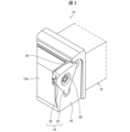
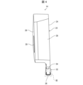
- FIG. 1 is a schematic perspective view of a cutting tool 10 according to an embodiment of the present disclosure.
- FIG. 2 is an enlarged view of part II in FIG.
- the cutting tool 10 is a turning tool used for turning among the cutting of the work material W (see FIG. 14).
- the cutting of the work material W includes outer diameter machining, inner diameter machining, grooving, cut-off machining, and the like.
- the cutting tool 10 may also have a holder 12 mounted on a lathe tool post and a cutting insert 14 held by the holder 12 .
- the holder 12 may be in the shape of a square bar extending from the front end 12a, which is the first end, to the rear end 12b, which is the second end.
- the holder 12 may have a bar shape other than a square bar shape such as a round bar shape. Examples of materials for the holder 12 include metals such as stainless steel, carbon steel, cast iron, and aluminum alloys.
- a pocket 16 for holding the cutting insert 14 may be located on the tip 12a side of the holder 12 .
- the length of the holder 12 may be set to 100 mm to 400 mm, for example.
- An injection port 18 for injecting coolant (cooling medium) toward the cutting insert 14 may be provided on the tip 12 a side of the holder 12 .
- the coolant is made of, for example, a water-insoluble oil agent or a water-soluble oil agent, and can be appropriately selected according to the material of the work material W to be used.
- water-insoluble oils include oil-based, inert extreme-pressure and active extreme-pressure cutting oils.
- water-soluble oils include cutting oils such as emulsions, solubles, and solutions.
- the coolant is not limited to a liquid, and may be a gas such as an inert gas.
- the cutting insert 14 may be positioned in the pocket 16 of the holder 12.
- the cutting insert 14 may be secured in the pocket 16 of the holder 12 by a locking screw 20 .
- the cutting insert 14 may be fixed in the pocket 16 of the holder 12 by a clamping member instead of the fixing screw 20 .
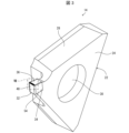
- FIG. 3 is a schematic perspective view of a cutting insert 14 according to an embodiment of the present disclosure.
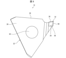
- 4 is a schematic top view of the cutting insert 14 shown in FIG. 3.
- FIG. 5 is a schematic right side view of the cutting insert 14 shown in FIG. 3.
- FIG. 6 is a schematic left side view of the cutting insert 14 shown in FIG. 3.
- FIG. 7 is a schematic front view of the cutting insert 14 shown in FIG. 3.
- FIG. 3 is a schematic perspective view of a cutting insert 14 according to an embodiment of the present disclosure.
- 4 is a schematic top view of
- the cutting insert 14 may have a base portion 22 for mounting in the pocket 16 of the holder 12 .
- the base portion 22 may have a substantially polygonal first main surface 24 such as a substantially triangular shape, and a second main surface 26 opposite to the first main surface 24 .
- the first principal surface 24 and the second principal surface 26 may each be substantially polygonal, such as substantially triangular.
- the base portion 22 may have a substantially polygonal plate shape such as a substantially triangular plate shape.
- the base portion 22 may have a plurality of sides located between the first major surface 24 and the second major surface 26 , any of the plurality of sides may be a planar upper substrate surface 28 . .
- the base portion 22 may have a through-hole 30 for inserting the fixing screw 20 in its central portion.
- the through hole 30 may be opened on the first main surface 24 side and the second main surface 26 side.
- the cutting insert 14 may have a cutting portion 32 that contacts the workpiece W to perform cutting.
- the cutting portion 32 may be provided only at one of the plurality of corners of the base portion 22 .
- the cutting portion 32 may be provided at each of a plurality of corners of the base portion 22 .
- the cutting portion 32 may be provided in a notch portion 34 provided at a corner portion of the base portion 22 .
- Examples of the material of the base portion 22 include cemented carbide, cermet, and the like.
- Compositions of cemented carbide include, for example, WC--Co, WC--TiC--Co and WC--TiC--TaC--Co.
- WC—Co is produced by adding cobalt (Co) powder to tungsten carbide (WC) and sintering it.
- WC-TiC-Co is obtained by adding titanium carbide (TiC) to WC-Co.
- WC--TiC--TaC--Co is obtained by adding tantalum carbide (TaC) to WC--TiC--Co.
- a cermet is a sintered composite material in which a metal is combined with a ceramic component. Specific examples of cermets include those containing titanium compounds such as titanium carbide (TiC) and titanium nitride (TiN) as main components.
- Examples of materials for the cutting portion 32 include hard materials such as cBN (Cubic Boron Nitride) and PCD (PolyCrystalline Diamond). If the material of the cutting portion 32 is different from that of the base portion 22, the cutting portion 32 may be joined to the base portion 22 with brazing material. If the material of the cutting portion 32 is the same as the material of the base portion 22 , the cutting portion 32 may be integrally formed with the base portion 22 .
- the surface of the cutting insert 14 may be coated with a coating using a chemical vapor deposition (CVD) method or a physical vapor deposition (PVD) method.
- CVD chemical vapor deposition
- PVD physical vapor deposition
- materials for the coating include titanium carbide (TiC), titanium nitride (TiN), titanium carbonitride (TiCN), and alumina (Al 2 O 3 ).
- FIG. 8 is an enlarged view of section VIII in FIG. 3 and is a schematic enlarged perspective view of a portion of the cutting insert 14 according to the embodiment of the present disclosure.
- FIG. 9 is a schematic enlarged top view of a portion of a cutting insert 14 according to an embodiment of the present disclosure.
- the cutting portion 32 of the cutting insert 14 may have an upper surface 36, which may function as a rake surface for channeling chips.
- Top surface 36 of cutting portion 32 along with substrate top surface 28 of substrate portion 22 , may form the top surface of cutting insert 14 .
- the upper surface 36 of the cutting portion 32 may have a first corner 38 , a second corner 40 , and a first side 42 connected to the first corner 38 and the second corner 40 .
- First corner 38 and second corner 40 may each have a curved shape.
- the first side 42 may be linear or slightly curved. The fact that the first side 42 is slightly curved means that the first side 42 is not limited to a strictly linear shape. Therefore, when the first side 42 is slightly curved, the radius of curvature of the first side 42 is ten times or more the radius of curvature of the first corner 38 and the second corner 40. Macroscopically, the first side 42 may be considered to have a linear shape compared to the corner 40 .
- the top surface 36 of the cutting portion 32 may also have a second side 44 connected to the first corner 38 and a third side 46 connected to the second corner 40 .
- the second side 44 and the third side 46 may be parallel.
- the second side 44 and the third side 46 may gradually approach as they move away from the first side 42 .
- the cutting portion 32 may have a front side surface 48 connected to the first side 42, and the front side surface 48 may function as a flank.
- the cutting portion 32 may have a first corner side 50 connected to the front side 48 and the first corner 38 and a second corner side 52 connected to the front side 48 and the second corner.
- the first corner side 50 and the second corner side 52 may each function as a flank.
- the first corner side 50 and the second corner side 52 may each have a width that narrows away from the top surface 36 .
- the cutting portion 32 has a first lateral side 54 connected to the first corner side 50 and the second side 44 and a second lateral side 56 connected to the second corner side 52 and the third side 46 .
- the first lateral side 54 and the second lateral side 56 may each function as a flank.
- the cutting portion 32 may have a front cutting edge FB located on the first side 42 where the upper surface 36 and the front side surface 48 intersect.
- the end cutting edge FB may be located on the entire area of the first side 42 or a part of the area.
- the cutting portion 32 may also have a first corner cutting edge CB1 located at a first corner 38 that is the intersection of the top surface 36 and the first corner side surface 50 .
- the first corner cutting edge CB1 may be positioned on the entire or partial area of the first corner 38 .
- the cutting portion 32 may have a second corner cutting edge CB2 located at the second corner 40 which is the intersection of the top surface 36 and the second corner side surface 52 .
- the second corner cutting edge CB2 may be positioned on the entire or partial area of the second corner 40 .
- the cutting portion 32 may have a first side edge SB1 located on the second side 44, which is the intersection of the upper surface 36 and the first lateral side surface 54.
- the first side blade SB1 may be positioned on the entire area of the second side 44 or on a partial area.
- the first side edge SB1 may have the function of finishing the surface of the workpiece W to be machined.
- the first side edge SB1 may be omitted from the cutting portion 32 to avoid interference between the second side 44 and the machining surface of the workpiece W.
- the cutting portion 32 may have a second side edge SB2 located on the third side 46 where the top surface 36 and the second side surface 56 intersect.
- the second side cutting edge SB2 may be located on the entire area of the third side 46 or on a part of the area.
- the second side edge SB2 may have a function of finishing the machined surface of the material W to be cut.
- the second side edge SB2 may be omitted from the cutting portion 32 to avoid interference between the third side 46 and the machining surface of the work
- the upper surface 36 of the cutting portion 32 may have a front land surface 58 for increasing the strength of the end cutting edge FB.
- a front land surface 58 may be located at the outer edge of the upper surface 36 of the cutting portion 32 and extend along the front cutting edge FB.
- the front land surface 58 may be connected to the front cutting edge FB.
- the upper surface 36 of the cutting portion 32 may have a first corner land surface 60 for increasing the strength of the first corner cutting edge CB1.
- the first corner land surface 60 may be located at the outer edge of the upper surface 36 of the cutting portion 32 and extend along the first corner cutting edge CB1.
- the first corner land surface 60 may be connected to the first corner cutting edge CB1.
- the upper surface 36 of the cutting portion 32 may have a second corner land surface 62 for increasing the strength of the second corner cutting edge CB2.
- the second corner land surface 62 may be located at the outer edge of the upper surface 36 of the cutting portion 32 and extend along the second corner cutting edge CB2.
- the second corner land surface 62 may be connected to the second corner cutting edge CB2.
- the upper surface 36 of the cutting portion 32 may have a first horizontal land surface 64 for increasing the strength of the first side edge SB1.
- the first lateral land surface 64 may be located at the outer edge of the upper surface 36 of the cutting portion 32 and extend along the first side edge SB1.
- the first lateral land surface 64 may be connected to the first side blade SB1.
- the upper surface 36 of the cutting portion 32 may have a second horizontal land surface 66 for increasing the strength of the second side edge SB2.
- the second lateral land surface 66 may be located at the outer edge of the upper surface 36 of the cutting portion 32 and extend along the second side edge SB2.
- the second lateral land surface 66 may be connected to the second side cutting edge SB2.
- the front land surface 58, the first corner land surface 60, the second corner land surface 62, the first lateral land surface 64, and the second lateral land surface 66 each have a width of 0.03 mm to 0.03 mm when viewed from above. It may be set as a strip-shaped area of about 0.5 mm.
- the upper surface 36 of the cutting portion 32 may have a flat upper end surface 68 located on the base portion 22 side.
- the top surface 36 of the cutting portion 32 may have a raised wall surface 70 located between the outer edge of the top surface 36 and the top surface 68 .
- the rising wall surface 70 may be inclined with respect to the upper end surface 68, and may have a function of curling chips to improve chip dischargeability.
- the upper surface 36 of the cutting portion 32 may have a front groove 72 extending inward from the front land surface 58 side toward the center of the upper surface 36 .
- the front groove 72 may have a function as a coolant reservoir (gap) for accumulating coolant.
- the front groove 72 may be spaced from the front land surface 58 and the front cutting edge FB.
- the front groove 72 may be connected to the front land surface 58 instead of being spaced from the front land surface 58 .
- the front groove 72 may be connected to the rising wall surface 70 . Also, the front groove 72 may be connected to the upper end surface 68 . Chips are likely to come into contact with the rising wall surface 70 , while chips are less likely to come into contact with the upper end face 68 . Therefore, when the front groove 72 is connected to the upper end surface 68 , coolant tends to flow into the front groove 72 from the upper end surface 68 . As a result, the coolant tends to accumulate in the front grooves 72 .
- the number of front grooves 72 is plural in the examples of FIGS. 8 and 9, it may be one.
- the plurality of front grooves 72 consist of a first front groove 72A and a second front groove 72B located closer to the first corner 38 than the first front groove 72A. may have.
- the length of the first front groove 72A may be the same as the length of the second front groove 72B.
- the upper surface 36 of the cutting portion 32 may have a first corner groove 74 extending inward from the first corner land surface 60 side.
- the first corner groove 74 may function as a coolant reservoir that stores coolant.
- the first corner groove 74 may be spaced apart from the first corner land surface 60 and the first corner cutting edge CB1.
- the first corner groove 74 may be connected to the first corner land surface 60 instead of being spaced apart from the first corner land surface 60 .
- the first corner groove 74 may be connected to the rising wall surface 70 . Also, the first corner groove 74 may be connected to the upper end surface 68 . When the first corner groove 74 is connected to the upper end surface 68 , coolant tends to flow into the first corner groove 74 from the upper end surface 68 . As a result, coolant tends to accumulate in the first corner grooves 74 . Although the number of the first corner grooves 74 is one in the examples of FIGS. 8 and 9, it may be plural.
- the first corner groove 74 may extend inward from the boundary between the front land surface 58 and the first corner land surface 60 .
- the first corner groove 74 is remote from the boundary between the front land surface 58 and the first corner land surface 60, but may be connected to that boundary.
- the first corner groove 74 may extend parallel to the front groove 72 .
- the length of the first corner groove 74 may be shorter than the length of the front groove 72 .
- the width of the first corner groove 74 may be narrower than the width of the front groove 72 .
- the depth of the first corner groove 74 may be the same as the depth of the front groove 72 .
- the upper surface 36 of the cutting portion 32 may have a second corner groove 76 extending inward from the second corner land surface 62 side.
- the second corner groove 76 may function as a coolant reservoir.
- the second corner groove 76 may be spaced from the second corner land surface 62 and the second corner cutting edge CB2.
- the second corner groove 76 may be connected to the second corner land surface 62 instead of being spaced apart from the second corner land surface 62 .
- the second corner groove 76 may be connected to the rising wall surface 70 . Also, the second corner groove 76 may be connected to the upper end surface 68 . When the second corner groove 76 is connected to the upper end surface 68 , coolant tends to flow into the second corner groove 76 from the upper end surface 68 . As a result, coolant tends to accumulate in the second corner grooves 76 . Although the number of the second corner grooves 76 is one in the examples of FIGS. 8 and 9, it may be plural.
- the second corner groove 76 may extend inward from the boundary between the front land surface 58 and the second corner land surface 62 .
- the second corner groove 76 is remote from the boundary between the front land surface 58 and the second corner land surface 62, but may be connected to that boundary.
- the second corner groove 76 may extend parallel to the front groove 72 .
- the length of the second corner groove 76 may be shorter than the length of the front groove 72 .
- the width of the second corner groove 76 may be narrower than the width of the front groove 72 .
- the depth of the second corner groove 76 may be the same as the depth of the front groove 72 .
- the upper surface 36 of the cutting portion 32 may have a first lateral groove 78 extending inward from the first lateral land surface 64 side.
- the first lateral groove 78 may function as a coolant reservoir.
- the first lateral groove 78 may be separated from the first lateral land surface 64 and the first side edge SB1.
- the first lateral groove 78 may be connected to the first lateral land surface 64 .
- the first lateral groove 78 may be connected to the rising wall surface 70 . Also, the first lateral groove 78 may be connected to the upper end surface 68 . When the first lateral grooves 78 are connected to the upper end surface 68 , coolant tends to flow into the first lateral grooves 78 from the upper end surface 68 . As a result, coolant tends to accumulate in the first lateral grooves 78 .
- the length of the first lateral grooves 78 may be longer than the length of the first corner grooves 74 . Although the number of the first lateral grooves 78 is plural in the examples of FIGS. 8 and 9, it may be one.
- the upper surface 36 of the cutting portion 32 may have a second lateral groove 80 extending inward from the second lateral land surface 66 side.
- the second lateral groove 80 may function as a coolant reservoir.
- the second lateral groove 80 may be separated from the second lateral land surface 66 and the second side edge SB2.
- the second lateral groove 80 may be connected to the second lateral land surface 66 .
- the second lateral groove 80 may be connected to the rising wall surface 70 . Also, the second lateral groove 80 may be connected to the upper end surface 68 . When the second lateral grooves 80 are connected to the upper end surface 68 , coolant tends to flow into the second lateral grooves 80 from the upper end surface 68 . As a result, coolant tends to accumulate in the second lateral grooves 80 .
- the length of the second lateral grooves 80 may be longer than the length of the second corner grooves 76 . Although the number of the second lateral grooves 80 is plural in the examples of FIGS. 8 and 9, it may be one.
- the cross-sectional shape along the width direction of the front groove 72, the first corner groove 74, the second corner groove 76, the first lateral groove 78, and the second lateral groove 80 may be V-shaped or rectangular.
- the lengths of the front groove 72, first corner groove 74, second corner groove 76, first lateral groove 78, and second lateral groove 80 may be set to, for example, 0.3 mm to 3 mm.
- the widths of the front groove 72, first corner groove 74, second corner groove 76, first lateral groove 78, and second lateral groove 80 may be set to, for example, 0.05 mm to 0.5 mm.
- the depths of the front grooves 72, the first corner grooves 74, the second corner grooves 76, the first lateral grooves 78, and the second lateral grooves 80 may be set to, for example, 0.05 mm to 0.5 mm.
- a larger cutting load is applied to the first corner cutting edge CB1 than the end cutting edge FB. Cracks are likely to occur at the one-corner cutting edge CB1.
- the strength of the first corner cutting edge CB1 is increased, Cracks are less likely to occur in the first corner cutting edge CB1.
- the cooling effect of the coolant on the end cutting edge FB and the first corner cutting edge CB1 is enhanced, while the durability of the first corner cutting edge CB1, in other words, the cutting insert 14 durability can be improved.
- the depth of the first corner groove 74 is the same as the depth of the front groove 72 as in the examples shown in FIGS. can be done. Thereby, the cooling effect of the first corner cutting edge CB1 by the coolant can be further enhanced. If the depths of the front grooves 72 and the first corner grooves 74 are not constant, the maximum depth of the front grooves 72 and the maximum depth of the first corner grooves 74 may be compared. That the depth of the first corner groove 74 is the same as the depth of the front groove 72 does not strictly mean that they are the same. If the depth of the first corner groove 74 is about 97% to 103% of the depth of the front groove 72, it may be regarded as the same.
- the front cutting edge BF or the first corner cutting edge CB1 is likely to deteriorate around the boundary between the first side 42 and the first corner 38 on the upper surface 36 of the cutting portion 32 .
- the first corner groove 74 extends inward from the boundary between the front land surface 58 and the first corner land surface 60 as in the examples shown in FIGS. Coolant can be supplied efficiently.
- the end cutting edge BF or the first corner cutting edge CB1 is less likely to deteriorate, and the durability of the cutting insert 14 is improved. can be improved.
- the first corner groove 74 extends parallel to the front groove 72, the gap between the first corner groove 74 and the front groove 72 is prevented from becoming locally small, and the durability of the cutting insert 14 is improved. can be further improved.
- the length of the first front groove 72A is the same as the length of the second front groove 72B, as in the examples shown in FIGS. can be made smaller. Thereby, the durability of the first corner cutting edge CB1, in other words, the durability of the cutting insert 14 can be further improved.
- FIG. 10 is a schematic enlarged perspective view of part of a cutting insert 14A according to Modification 1 of the embodiment of the present disclosure.
- the cutting insert 14A according to Modification 1 of the embodiment of the present disclosure has the same configuration as the cutting insert 14 except for a part.
- the points that differ from the configuration of the cutting insert 14 will be described.
- members having the same functions as the members explained in the embodiment are denoted by the same reference numerals.
- the upper surface 36 of the cutting portion 32 may have two first corner grooves 74 extending inward from the first corner land surface 60 side.
- One first corner groove 74 may extend inward from the boundary between the front land surface 58 and the first corner land surface 60 .
- the other first corner groove 74 may extend inward from the central portion side of the first corner land surface 60 .
- the upper surface 36 of the cutting portion 32 may have two second corner grooves 76 extending inward from the second corner land surface 62 side.
- One of the second corner grooves 76 may extend inward from the boundary between the front land surface 58 and the second corner land surface 62 .
- the other second corner groove 76 may extend inward from the central portion side of the second corner land surface 62 .
- FIG. 11 is a schematic enlarged perspective view of part of a cutting insert 14B according to Modification 2 of the embodiment of the present disclosure.
- the cutting insert 14B according to Modification 2 of the embodiment of the present disclosure has the same configuration as the cutting insert 14 except for a part.
- the points that differ from the configuration of the cutting insert 14 will be described.
- members having the same functions as the members explained in the embodiment are denoted by the same reference numerals.
- the upper surface 36 of the cutting portion 32 may have one first lateral groove 78 extending inward from the first lateral land surface 64 side.
- the first lateral groove 78 may extend inward from the side of the boundary between the first lateral land surface 64 and the first corner land surface 60 .
- the upper surface 36 of the cutting portion 32 may have one second lateral groove 80 extending inward from the second lateral land surface 66 side.
- the second lateral groove 80 may extend inward from the side of the boundary between the second lateral land surface 66 and the first corner land surface 60 .
- each of the first corner side 50 and the second corner side 52 may become narrower with increasing distance from the upper surface 36 .
- FIG. 12 is a schematic enlarged perspective view of part of a cutting insert 14C according to Modification 3 of the embodiment of the present disclosure.
- the cutting insert 14C according to Modification 3 of the embodiment of the present disclosure has the same configuration as the cutting insert 14B except for a part.
- the points that differ from the configuration of the cutting insert 14B will be described.
- members having the same functions as the members explained in Modification 2 of the embodiment are denoted by the same reference numerals.
- the plurality of front grooves 72 may have a first front groove 72A and a second front groove 72B positioned closer to the first corner 38 than the first front groove 72A.
- the length of the first front groove 72A may be longer than the length of the second front groove 72B.
- FIG. 13 is a schematic enlarged perspective view of part of a cutting insert 14D according to Modification 4 of the embodiment of the present disclosure.
- the cutting insert 14D according to Modification 4 of the embodiment of the present disclosure has the same configuration as the cutting insert 14C except for a part.
- the points that differ from the configuration of the cutting insert 14C will be described.
- members having the same functions as the members explained in Modification 3 of the embodiment are denoted by the same reference numerals.
- the upper surface 36 of the cutting portion 32 may have a plurality of first lateral grooves 78 extending inward from the first lateral land surface 64 side.
- One first lateral groove 78 may extend inward from the side of the boundary between the first lateral land surface 64 and the first corner land surface 60 .
- the upper surface 36 of the cutting portion 32 may have a plurality of second lateral grooves 80 extending inward from the second lateral land surface 66 side.
- One second lateral groove 80 may extend inward from the side of the boundary between the second lateral land surface 66 and the first corner land surface 60 .
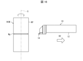
- FIGS. 14 to 16 are schematic diagrams for explaining the method for manufacturing a cut product according to the embodiment.
- the method for manufacturing a cut workpiece according to the embodiment is a method for manufacturing a cut workpiece M, which is a workpiece W that has been machined.
- the first step is a step of rotating the work material W around its axis S.
- the second step is the step of bringing the cutting insert 14 of the cutting tool 10 into contact with the rotating work W.
- the third step is the step of separating the cutting tool 10 from the work material W.
- Examples of the material of the work material W include stainless steel, carbon steel, alloy steel, cast iron, and non-ferrous metals.
- the cutting tool 10 is mounted on the turret of the lathe, and the work material W is mounted on the chuck of the lathe.
- the chuck is rotated to rotate the workpiece W around its axis S (first step).
- the cutting tool 10 is brought closer to the work W, and the cutting insert 14 is applied to the outer peripheral surface Wf of the rotating work W.
- the part 32 is brought into contact with the workpiece W to give a cut (second step).
- the work material W is cut, and the work groove Wg can be formed in the outer peripheral surface Wf of the work material W.
- the cutting tool 10 is separated from the work material W by moving the cutting tool 10 in the direction of the arrow D2 (third step).
- the cutting of the work material W is completed, and the machined product M, which is the work material W that has been cut, can be manufactured. Since the cutting insert 14 has excellent cutting ability for the reason described above, it is possible to manufacture a machined workpiece M with excellent machining accuracy.
- the cutting portion 32 of the cutting insert 14 may be repeatedly brought into contact with different portions of the work W while the work W is being rotated.
- the cutting tool 10 is brought closer to the work material W, but since the cutting tool 10 and the work material W should be relatively brought closer, for example, the work material W is brought closer to the cutting tool 10 may In this respect, when the cutting tool 10 is separated from the work material W, the same operation is performed.
- the front land surface 58, the first corner land surface 60, the second corner land surface 62, the first lateral land surface 64, and the second lateral land surface 66 may each be honed surfaces formed by so-called honing.
- the rising wall surface 70 may be used as a land surface. In such a case, it is possible to distinguish between the honing surface having a curved surface shape and the land surface having a planar shape.
Landscapes
- Engineering & Computer Science (AREA)
- Mechanical Engineering (AREA)
- Milling Processes (AREA)
Abstract
切削インサートは、上面と、前側面と、第1コーナ側面と、前切刃と、第1コーナ切刃と、を有する。上面は、前切刃に沿って延びた前ランド面と、第1コーナ切刃に沿って延びた第1コーナランド面と、前ランド面の側から内方に向かって延びた前溝と、第1コーナランド面の側から内方に向かって延びた第1コーナ溝と、を有する。第1コーナ溝の長さが、前溝の長さよりも短い。
Description
本開示は、被削材の切削加工に用いられる切削インサート、切削工具、及び切削加工物の製造方法に関する。
被削材を切削加工する際に用いられる切削インサートとして、例えば特許文献1及び2に記載の切削インサートが挙げられる。切削加工時において、通常、切屑の除去及び切削インサートの冷却を行うために、切削インサートに向かってクーラント(冷却溶媒)が噴射される。クーラントによる切刃の冷却効果を高めるため、特許文献1及び2に記載の切削インサートには溝が設けられている。
本開示に係る切削インサートは、第1コーナと、第2コーナと、前記第1コーナ及び前記第2コーナに接続された第1辺と、を有する上面を有する。本開示に係る切削インサートは、前記第1辺に接続された前側面と、前記第1コーナに接続された第1コーナ側面と、前記第1辺に位置する前切刃と、前記第1コーナに位置する第1コーナ切刃と、を有する。前記上面は、前記上面の外縁に位置し、前記前切刃に沿って延びた前ランド面と、前記上面の外縁に位置し、前記第1コーナ切刃に沿って延びた第1コーナランド面と、前記前ランド面の側から内方に向かって延びた前溝と、前記第1コーナランド面の側から内方に向かって延びた第1コーナ溝と、を更に有する。前記第1コーナ溝の長さが、前記前溝の長さよりも短い。
特許文献1及び2に記載の切削インサートには溝が設けられることによってクーラントによる切刃の冷却効果が高められる一方で、切削インサートの耐久性が低下する恐れがある。即ち、良好な冷却効果と切削インサートの耐久性の向上の両立が求められている。
本開示によれば、クーラントによる切刃の冷却効果を高めつつ、切削インサートの耐久性を向上させることができる。
以下、本開示の実施形態に係る切削インサート、切削工具、及び切削加工物の製造方法について、図面を用いて詳細に説明する。但し、以下で参照する各図は、説明の便宜上、実施形態を説明する上で必要な構成要素のみを簡略化して示したものである。従って、本開示の実施形態に係る切削インサートは、参照する各図に示されていない任意の構成要素を備え得る。各図中の構成要素の寸法は、実際の構成要素の寸法および各部材の寸法比率等を忠実に表したものではない。また、本開示において、平行とは、厳密な平行に限るものでなく、±5度程度の誤差を許容する意である。
<切削工具>
図1及び図2を参照して、本開示の実施形態に係る切削工具10について説明する。図1は、本開示の実施形態に係る切削工具10の模式的な斜視図である。図2は、図1におけるII部の拡大図である。
図1及び図2を参照して、本開示の実施形態に係る切削工具10について説明する。図1は、本開示の実施形態に係る切削工具10の模式的な斜視図である。図2は、図1におけるII部の拡大図である。
図1及び図2に示す例のように、本開示の実施形態に係る切削工具10は、被削材W(図14参照)の切削加工のうち旋削加工に用いられる旋削工具である。被削材Wの切削加工には、外径加工、内径加工、溝入れ加工、及び突っ切り加工等が含まれる。また、切削工具10は、旋盤の刃物台に装着されるホルダ12と、ホルダ12に保持される切削インサート14とを有してもよい。
ホルダ12は、第1端である先端12aから第2端である後端12bにかけて延びた角棒形状であってもよい。ホルダ12は、丸棒形状等の角棒形状以外の棒形状であってもよい。ホルダ12の材質としては、例えば、ステンレス鋼、炭素鋼、鋳鉄、アルミ合金等の金属等が挙げられる。ホルダ12の先端12aの側には、切削インサート14を保持するためのポケット16が位置してもよい。ホルダ12の長さは、例えば、100mm~400mmに設定されてもよい。
ホルダ12の先端12aの側には、切削インサート14に向かってクーラント(冷却媒体)を噴射するための噴射口18が設けられてもよい。クーラントは、例えば、不水溶性油剤又は水溶性油剤からなり、被削材Wの材質に応じて適宜選択して用いることができる。不水溶性油剤としては、例えば、油性形、不活性極圧形及び活性極圧形の切削油が挙げられる。水溶性油剤としては、例えば、エマルジョン、ソリューブル及びソリューション等の切削油が挙げられる。また、クーラントは、液体に限定されるものではなく、不活性ガス等の気体であってもよい。
切削インサート14は、ホルダ12のポケット16に位置してもよい。切削インサート14は、固定ネジ20によってホルダ12のポケット16に固定されてもよい。切削インサート14は、固定ネジ20の代わりにクランプ部材によってホルダ12のポケット16に固定されてもよい。
<切削インサート>
図3から図7を参照して、本開示の実施形態に係る切削インサート14の構成について説明する。図3は、本開示の実施形態に係る切削インサート14の模式的な斜視図である。図4は、図3に示す切削インサート14の模式的な上面図である。図5は、図3に示す切削インサート14の模式的な右側面図である。図6は、図3に示す切削インサート14の模式的な左側面図である。図7は、図3に示す切削インサート14の模式的な正面図である。
図3から図7を参照して、本開示の実施形態に係る切削インサート14の構成について説明する。図3は、本開示の実施形態に係る切削インサート14の模式的な斜視図である。図4は、図3に示す切削インサート14の模式的な上面図である。図5は、図3に示す切削インサート14の模式的な右側面図である。図6は、図3に示す切削インサート14の模式的な左側面図である。図7は、図3に示す切削インサート14の模式的な正面図である。
図3から図7に示す例のように、本開示の実施形態に係る切削インサート14は、ホルダ12のポケット16に取付けるための基体部22を有してもよい。基体部22は、略三角形等の略多角形の第1主面24と、第1主面24の反対に位置する第2主面26とを有してもよい。第1主面24及び第2主面26は、それぞれ略三角形等の略多角形であってもよい。換言すれば、基体部22は、略三角板形状等の略多角板形状であってもよい。
基体部22は、第1主面24と第2主面26との間に位置する複数の側面を有してもよく、複数の側面のいずれかは、平らな基体上面28であってもよい。基体部22は、その中央部に、固定ネジ20を挿通させるための貫通孔30を有してもよい。貫通孔30は、第1主面24の側及び第2主面26の側に開口されてもよい。
本開示の実施形態に係る切削インサート14は、被削材Wに接触して切削加工を行う切削部32を有してもよい。切削部32は、基体部22の複数の角部のうち1つの角部にのみ設けられてもよい。切削部32は、基体部22の複数の角部のそれぞれに設けられてもよい。切削部32は、基体部22の角部に有した切欠部34に設けられてもよい。
基体部22の材質としては、例えば、超硬合金又はサーメット等が挙げられる。超硬合金の組成としては、例えば、WC-Co、WC-TiC-Co及びWC-TiC-TaC-Coが挙げられる。WC-Coは、炭化タングステン(WC)にコバルト(Co)の粉末を加えて焼結して生成される。WC-TiC-Coは、WC-Coに炭化チタン(TiC)を添加したものである。WC-TiC-TaC-Coは、WC-TiC-Coに炭化タンタル(TaC)を添加したものである。また、サーメットは、セラミック成分に金属を複合させた焼結複合材料である。具体的には、サーメットとして、炭化チタン(TiC)、及び窒化チタン(TiN)等のチタン化合物を主成分としたものが挙げられる。
切削部32の材質としては、例えば、cBN(Cubic Boron Nitride)、PCD(PolyCrystalline Diamond)等の硬質材料が挙げられる。切削部32の材質が基体部22の材質と異なる場合には、切削部32は、基体部22にろう材によって接合されてもよい。切削部32の材質が基体部22の材質と同じ場合には、切削部32は、基体部22と一体形成されてもよい。
切削インサート14の表面には、化学蒸着(CVD)法又は物理蒸着(PVD)法を用いて被膜がコーティングされていてもよい。被膜の材質としては、例えば、炭化チタン(TiC)、窒化チタン(TiN)、炭窒化チタン(TiCN)、又はアルミナ(Al2O3)等が挙げられる。
図8及び図9を参照して、本開示の実施形態に係る切削インサート14の切削部32の具体的な構成について説明する。図8は、図3におけるVIII部の拡大図であり、本開示の実施形態に係る切削インサート14の一部の模式的な拡大斜視図である。図9は、本開示の実施形態の係る切削インサート14の一部の模式的な拡大上面図である。
図8及び図9に示す例のように、切削インサート14の切削部32は、上面36を有してもよく、上面36は、切屑を流すためのすくい面としての機能を有してもよい。切削部32の上面36は、基体部22の基体上面28と共に切削インサート14の上面を構成してもよい。
切削部32の上面36は、第1コーナ38と、第2コーナ40と、第1コーナ38及び第2コーナ40に接続された第1辺42と、を有してもよい。第1コーナ38及び第2コーナ40は、それぞれ湾曲形状であってもよい。第1辺42は、直線形状であってもよく、僅かに湾曲してもよい。なお、第1辺42が僅かに湾曲しているとは、第1辺42が厳密な直線形状には限定されないことを意味している。そのため、第1辺42が僅かに湾曲している場合における第1辺42の曲率半径は、第1コーナ38及び第2コーナ40の曲率半径の10倍以上であり、第1コーナ38及び第2コーナ40と比較して、巨視的には第1辺42が直線形状であると見なしてもよい。また、切削部32の上面36は、第1コーナ38に接続された第2辺44と、第2コーナ40に接続された第3辺46と、を有してもよい。第2辺44及び第3辺46は、平行であってもよい。あるいは、第2辺44及び第3辺46は、第1辺42から離れるにしたがって徐々に近づいてもよい。
切削部32は、第1辺42に接続された前側面48を有してもよく、前側面48は、逃げ面としての機能を有してもよい。切削部32は、前側面48及び第1コーナ38に接続された第1コーナ側面50と、前側面48及び第2コーナに接続された第2コーナ側面52と、を有してもよい。第1コーナ側面50及び第2コーナ側面52は、それぞれ、逃げ面としての機能を有してもよい。第1コーナ側面50及び第2コーナ側面52は、それぞれ、上面36から離れるにしたがって幅が狭くなるようにしてもよい。切削部32は、第1コーナ側面50及び第2辺44に接続された第1横側面54と、第2コーナ側面52及び第3辺46に接続された第2横側面56と、を有してもよい。第1横側面54及び第2横側面56は、それぞれ、逃げ面としての機能を有してもよい。
切削部32は、上面36と前側面48との交わりである第1辺42に位置する前切刃FBを有してもよい。前切刃FBは、第1辺42の全域又は一部の領域に位置してもよい。また、切削部32は、上面36と第1コーナ側面50との交わりである第1コーナ38に位置する第1コーナ切刃CB1を有してもよい。第1コーナ切刃CB1は、第1コーナ38の全域又は一部の領域に位置してもよい。更に、切削部32は、上面36と第2コーナ側面52との交わりである第2コーナ40に位置する第2コーナ切刃CB2を有してもよい。第2コーナ切刃CB2は、第2コーナ40の全域又は一部の領域に位置してもよい。
切削部32は、上面36と第1横側面54との交わりである第2辺44に位置する第1横切刃SB1を有してもよい。第1横切刃SB1は、第2辺44の全域又は一部の領域に位置してもよい。第1横切刃SB1は、被削材Wの加工面を仕上げる機能を有してもよい。切削部32から第1横切刃SB1を省略して、第2辺44と被削材Wの加工面との干渉を回避するようにしてもよい。また、切削部32は、上面36と第2横側面56との交わりである第3辺46に位置する第2横切刃SB2を有してもよい。第2横切刃SB2は、第3辺46の全域又は一部の領域に位置してもよい。第2横切刃SB2は、被削材Wの加工面を仕上げる機能を有してもよい。切削部32から第2横切刃SB2を省略して、第3辺46と被削材Wの加工面との干渉を回避するようにしてもよい。
切削部32の上面36は、前切刃FBの強度を高めるための前ランド面58を有してもよい。前ランド面58は、切削部32の上面36の外縁に位置し、前切刃FBに沿って延びてもよい。前ランド面58は、前切刃FBに接続されてもよい。また、切削部32の上面36は、第1コーナ切刃CB1の強度を高めるための第1コーナランド面60を有してよい。第1コーナランド面60は、切削部32の上面36の外縁に位置し、第1コーナ切刃CB1に沿って延びてもよい。第1コーナランド面60は、第1コーナ切刃CB1に接続されてもよい。更に、切削部32の上面36は、第2コーナ切刃CB2の強度を高めるための第2コーナランド面62を有してよい。第2コーナランド面62は、切削部32の上面36の外縁に位置し、第2コーナ切刃CB2に沿って延びてもよい。第2コーナランド面62は、第2コーナ切刃CB2に接続されてもよい。
切削部32の上面36は、第1横切刃SB1の強度を高めるための第1横ランド面64を有してよい。第1横ランド面64は、切削部32の上面36の外縁に位置し、第1横切刃SB1に沿って延びてもよい。第1横ランド面64は、第1横切刃SB1に接続されてもよい。また、切削部32の上面36は、第2横切刃SB2の強度を高めるための第2横ランド面66を有してよい。第2横ランド面66は、切削部32の上面36の外縁に位置し、第2横切刃SB2に沿って延びてもよい。第2横ランド面66は、第2横切刃SB2に接続されてもよい。
前ランド面58、第1コーナランド面60、第2コーナランド面62、第1横ランド面64、及び第2横ランド面66は、それぞれ、上面視した場合に、例えば、幅0.03mm~0.5mm程度の帯形状の領域として設定されてもよい。
切削部32の上面36は、基体部22の側に位置する平らな上端面68を有してもよい。切削部32の上面36は、上面36の外縁と上端面68の間に位置する立ち上がり壁面70を有してもよい。立ち上がり壁面70は、上端面68に対して傾斜してもよく、切屑をカールさせて切屑排出性を高める機能を有してもよい。
切削部32の上面36は、前ランド面58の側から内方である上面36の中央に向かって延びた前溝72を有してもよい。前溝72は、クーラントを溜めるためのクーラント溜まり(隙間)としての機能を有してもよい。前溝72は、前ランド面58及び前切刃FBから離れてもよい。前溝72は、前ランド面58から離れる代わりに、前ランド面58に接続されてもよい。
前溝72は、立ち上がり壁面70に接続されてもよい。また、前溝72は、上端面68に接続されてもよい。立ち上がり壁面70には切屑が接触しやすい一方で、上端面68には切屑が接触しにくい。そのため、前溝72が上端面68に接続されている場合には、クーラントが上端面68から前溝72に流れ込みやすい。結果として、前溝72にクーラントが溜められ易い。
図8及び図9の例においては、前溝72の数は、複数であるが、1つでもよい。前溝72の数が複数の場合には、複数の前溝72は、第1前溝72Aと、第1前溝72Aよりも第1コーナ38の近くに位置する第2前溝72Bと、を有してもよい。第1前溝72Aの長さは、第2前溝72Bの長さと同じであってもよい。
切削部32の上面36は、第1コーナランド面60の側から内方に向かって延びた第1コーナ溝74を有してもよい。第1コーナ溝74は、クーラントを溜めるクーラント溜まりとしての機能を有してもよい。第1コーナ溝74は、第1コーナランド面60及び第1コーナ切刃CB1から離れてもよい。第1コーナ溝74は、第1コーナランド面60から離れる代わりに、第1コーナランド面60に接続されてもよい。
第1コーナ溝74は、立ち上がり壁面70に接続されてもよい。また、第1コーナ溝74は、上端面68に接続されてもよい。第1コーナ溝74が上端面68に接続されている場合には、クーラントが上端面68から第1コーナ溝74に流れ込みやすい。結果として、第1コーナ溝74にクーラントが溜められ易い。図8及び図9の例においては、第1コーナ溝74の数は1つであるが、複数であってもよい。
第1コーナ溝74は、前ランド面58と第1コーナランド面60との境界の側から内方向に向かって延びてもよい。第1コーナ溝74は、前ランド面58と第1コーナランド面60との境界から離れているが、その境界に接続されてもよい。第1コーナ溝74は、前溝72に平行に延びてもよい。また、第1コーナ溝74の長さは、前溝72の長さよりも短くてもよい。第1コーナ溝74の幅は、前溝72の幅よりも狭くてもよい。第1コーナ溝74の深さは、前溝72の深さと同じであってもよい。
切削部32の上面36は、第2コーナランド面62の側から内方に向かって延びた第2コーナ溝76を有してもよい。第2コーナ溝76は、クーラント溜まりとしての機能を有してもよい。第2コーナ溝76は、第2コーナランド面62及び第2コーナ切刃CB2から離れてもよい。第2コーナ溝76は、第2コーナランド面62から離れる代わりに、第2コーナランド面62に接続されてもよい。
第2コーナ溝76は、立ち上がり壁面70に接続されてもよい。また、第2コーナ溝76は、上端面68に接続されてもよい。第2コーナ溝76が上端面68に接続されている場合には、クーラントが上端面68から第2コーナ溝76に流れ込みやすい。結果として、第2コーナ溝76にクーラントが溜められ易い。図8及び図9の例においては、第2コーナ溝76の数は1つであるが、複数であってもよい。
第2コーナ溝76は、前ランド面58と第2コーナランド面62との境界の側から内方向に向かって延びてもよい。第2コーナ溝76は、前ランド面58と第2コーナランド面62との境界から離れているが、その境界に接続されてもよい。第2コーナ溝76は、前溝72に平行に延びてもよい。また、第2コーナ溝76の長さは、前溝72の長さよりも短くてもよい。第2コーナ溝76の幅は、前溝72の幅よりも狭くてもよい。第2コーナ溝76の深さは、前溝72の深さと同じであってもよい。
切削部32の上面36は、第1横ランド面64の側から内方に向かって延びた第1横溝78を有してもよい。第1横溝78は、クーラント溜まりとしての機能を有してもよい。第1横溝78は、第1横ランド面64及び第1横切刃SB1から離れてもよい。第1横溝78は、第1横ランド面64に接続されてもよい。
第1横溝78は、立ち上がり壁面70に接続されてもよい。また、第1横溝78は、上端面68に接続されてもよい。第1横溝78が上端面68に接続されている場合には、クーラントが上端面68から第1横溝78に流れ込みやすい。結果として、第1横溝78にクーラントが溜められ易い。第1横溝78の長さは、第1コーナ溝74の長さよりも長くてもよい。図8及び図9の例においては、第1横溝78の数は複数であるが、1つであってもよい。
切削部32の上面36は、第2横ランド面66の側から内方に向かって延びた第2横溝80を有してもよい。第2横溝80は、クーラント溜まりとしての機能を有してもよい。第2横溝80は、第2横ランド面66及び第2横切刃SB2から離れてもよい。第2横溝80は、第2横ランド面66に接続されてもよい。
第2横溝80は、立ち上がり壁面70に接続されてもよい。また、第2横溝80は、上端面68に接続されてもよい。第2横溝80が上端面68に接続されている場合には、クーラントが上端面68から第2横溝80に流れ込みやすい。結果として、第2横溝80にクーラントが溜められ易い。第2横溝80の長さは、第2コーナ溝76の長さよりも長くてもよい。図8及び図9の例においては、第2横溝80の数は複数であるが、1つであってもよい。
前溝72、第1コーナ溝74、第2コーナ溝76、第1横溝78、及び第2横溝80の幅方向に沿った断面形状は、それぞれ、V字形状又は矩形状であってもよい。前溝72、第1コーナ溝74、第2コーナ溝76、第1横溝78、及び第2横溝80の長さは、例えば、0.3mm~3mmに設定されてもよい。前溝72、第1コーナ溝74、第2コーナ溝76、第1横溝78、及び第2横溝80の幅は、例えば、0.05mm~0.5mmに設定されてもよい。前溝72、第1コーナ溝74、第2コーナ溝76、第1横溝78、及び第2横溝80の深さは、例えば、0.05mm~0.5mmに設定されてもよい。
図3から図8に示す例のように、切削部32の上面36が前溝72及び第1コーナ溝74を有する場合には、前切刃FB及び第1コーナ切刃CB1にクーラントを効率よく供給することができる。これにより、クーラントによる前切刃FB及び第1コーナ切刃CB1の冷却効果を高めることができる。
第1コーナ切刃CB1は、前切刃FBに比較して、大きな切削負荷が加わり、第1コーナ溝74が前溝72と同じ形状(同じ幅、同じ長さ)である場合には、第1コーナ切刃CB1においてクラックが生じ易い。これに対して、図3から図8に示す例のように、第1コーナ溝74の長さが前溝72の長さよりも短い場合には、第1コーナ切刃CB1の強度を高めて、第1コーナ切刃CB1においてクラックが生じ難くなる。
つまり、図3から図8に示す例によれば、クーラントによる前切刃FB及び第1コーナ切刃CB1の冷却効果を高めつつ、第1コーナ切刃CB1の耐久性、換言すれば、切削インサート14の耐久性を向上させることができる。
図3から図8に示す例のように、第1コーナ溝74の幅が前溝72の幅よりも狭い場合には、第1コーナ切刃CB1の強度をより高めて、第1コーナ切刃CB1においてクラックがより生じ難くなる。これにより、切削インサート14の耐久性をより向上させることができる。
図3から図8に示す例のように、第1コーナ溝74の深さが前溝72の深さと同じである場合には、第1コーナ溝74に溜めるクーラントの量を十分に確保することができる。これにより、クーラントによる第1コーナ切刃CB1の冷却効果をより高めることができる。前溝72及び第1コーナ溝74の深さが一定ではない場合、前溝72の深さの最大値及び第1コーナ溝74の深さの最大値を比較すればよい。第1コーナ溝74の深さが前溝72の深さと同じであるとは、厳密な意味で同じであることを求めない。第1コーナ溝74の深さが前溝72の深さに対して97%~103%程度であれば、同じであると見なしてもよい。
切削部32の上面36における第1辺42と第1コーナ38との境界周辺において、前切刃BF又は第1コーナ切刃CB1が劣化し易いことが判明した。図3から図8に示す例のように、第1コーナ溝74が前ランド面58と第1コーナランド面60との境界の側から内方向に向かって延びている場合には、その境界にクーラントを効率よく供給することができる。これにより、切削部32の上面36における第1辺42と第1コーナ38との境界周辺において、前切刃BF又は第1コーナ切刃CB1が劣化し難くなり、切削インサート14の耐久性をより向上させることができる。特に、第1コーナ溝74が前溝72に平行に延びている場合には、第1コーナ溝74と前溝72の間隔が局所的に小さくなることを抑えて、切削インサート14の耐久性を更に向上させることができる。
図3から図8に示す例のように、第1前溝72Aの長さが第2前溝72Bの長さと同じである場合には、前切刃FBの全域に供給されるクーラントのバラツキを小さくできる。これにより、第1コーナ切刃CB1の耐久性、換言すれば、切削インサート14の耐久性をより向上させることができる。
図3から図8に示す例のように、第2コーナ溝76の長さが前溝72の長さよりも短い場合には、第2コーナ切刃CB2の強度を高めて、第2コーナ切刃CB2においてクラックが生じ難くなる。これにより、第2コーナ切刃CB2の耐久性の耐久性を向上させることができる。
図3から図8に示す例のように、第1横溝78の長さが第1コーナ溝74の長さよりも長い場合には、第1横溝78に溜めるクーラントの量を十分に確保することができる。これにより、クーラントによる第1横切刃SB1の冷却効果を高めることができる。
<実施形態の変形例1>
図10を参照して、本開示の実施形態の変形例1に係る切削インサート14Aの構成について説明する。図10は、本開示の実施形態の変形例1に係る切削インサート14Aの一部の模式的な拡大斜視図である。
図10を参照して、本開示の実施形態の変形例1に係る切削インサート14Aの構成について説明する。図10は、本開示の実施形態の変形例1に係る切削インサート14Aの一部の模式的な拡大斜視図である。
図10に示す例のように、本開示の実施形態の変形例1に係る切削インサート14Aは、一部を除き、切削インサート14と同一の構成を有している。切削インサート14Aの構成のうち、切削インサート14の構成と異なる点について説明する。説明の便宜上、実施形態にて説明した部材と同じ機能を有する部材については、同じ符号を付記する。
切削部32の上面36は、第1コーナランド面60の側から内方に向かって延びた2つの第1コーナ溝74を有してもよい。一方の第1コーナ溝74は、前ランド面58と第1コーナランド面60との境界の側から内方向に向かって延びてもよい。他方の第1コーナ溝74は、第1コーナランド面60の中央部の側から内方向に向かって延びてもよい。
切削部32の上面36は、第2コーナランド面62の側から内方に向かって延びた2つの第2コーナ溝76を有してもよい。一方の第2コーナ溝76は、前ランド面58と第2コーナランド面62との境界の側から内方向に向かって延びてもよい。他方の第2コーナ溝76は、第2コーナランド面62の中央部の側から内方向に向かって延びてもよい。
図10に示す例のように、切削部32の上面36が2つの第1コーナ溝74を有している場合には、第1コーナ切刃CB1にクーラントを十分に供給して、クーラントによる第1コーナ切刃CB1の冷却効果を高めることができる。
<実施形態の変形例2>
図11を参照して、本開示の実施形態の変形例2に係る切削インサート14Bの構成について説明する。図11は、本開示の実施形態の変形例2に係る切削インサート14Bの一部の模式的な拡大斜視図である。
図11を参照して、本開示の実施形態の変形例2に係る切削インサート14Bの構成について説明する。図11は、本開示の実施形態の変形例2に係る切削インサート14Bの一部の模式的な拡大斜視図である。
図11に示す例のように、本開示の実施形態の変形例2に係る切削インサート14Bは、一部を除き、切削インサート14と同一の構成を有している。切削インサート14Bの構成のうち、切削インサート14の構成と異なる点について説明する。説明の便宜上、実施形態にて説明した部材と同じ機能を有する部材については、同じ符号を付記する。
切削部32の上面36は、第1横ランド面64の側から内方に向かって延びた1つの第1横溝78を有してもよい。第1横溝78は、第1横ランド面64と第1コーナランド面60との境界の側から内方向に向かって延びてもよい。
切削部32の上面36は、第2横ランド面66の側から内方に向かって延びた1つの第2横溝80を有してもよい。第2横溝80は、第2横ランド面66と第1コーナランド面60との境界の側から内方向に向かって延びてもよい。
第1コーナ側面50及び第2コーナ側面52は、それぞれ、上面36から離れるにしたがって幅がより狭くなるようにしてもよい。
図11に示す例のように、第1横溝78が第1横ランド面64と第1コーナランド面60との境界の側から内方向に向かって延びている場合には、その境界にクーラントを効率よく供給することができる。これにより、切削部32の上面36における第2辺44と第1コーナ38との境界周辺において、第1横切刃CF又は第1コーナ切刃CB1が劣化し難くなり、切削インサート14の耐久性をより向上させることができる。
<実施形態の変形例3>
図12を参照して、本開示の実施形態の変形例3に係る切削インサート14Cの構成について説明する。図12は、本開示の実施形態の変形例3に係る切削インサート14Cの一部の模式的な拡大斜視図である。
図12を参照して、本開示の実施形態の変形例3に係る切削インサート14Cの構成について説明する。図12は、本開示の実施形態の変形例3に係る切削インサート14Cの一部の模式的な拡大斜視図である。
図12に示す例のように、本開示の実施形態の変形例3に係る切削インサート14Cは、一部を除き、切削インサート14Bと同一の構成を有している。切削インサート14Cの構成のうち、切削インサート14Bの構成と異なる点について説明する。説明の便宜上、実施形態の変形例2にて説明した部材と同じ機能を有する部材については、同じ符号を付記する。
複数の前溝72は、第1前溝72Aと、第1前溝72Aよりも第1コーナ38の近くに位置する第2前溝72Bとを有してもよい。第1前溝72Aの長さは、第2前溝72Bの長さよりも長くてもよい。
図12に示す例のように、第1前溝72Aの長さが第2前溝72Bの長さよりも長い場合には、放熱され難い前切刃bFの中央部にクーラントを効率よく供給することができる。これにより、クーラントによる前切刃FBの冷却効果をより高めることができる。
<実施形態の変形例4>
図13を参照して、本開示の実施形態の変形例4に係る切削インサート14Dの構成について説明する。図13は、本開示の実施形態の変形例4に係る切削インサート14Dの一部の模式的な拡大斜視図である。
図13を参照して、本開示の実施形態の変形例4に係る切削インサート14Dの構成について説明する。図13は、本開示の実施形態の変形例4に係る切削インサート14Dの一部の模式的な拡大斜視図である。
図13に示す例のように、本開示の実施形態の変形例4に係る切削インサート14Dは、一部を除き、切削インサート14Cと同一の構成を有している。切削インサート14Dの構成のうち、切削インサート14Cの構成と異なる点について説明する。説明の便宜上、実施形態の変形例3にて説明した部材と同じ機能を有する部材については、同じ符号を付記する。
切削部32の上面36は、第1横ランド面64の側から内方に向かって延びた複数の第1横溝78を有してもよい。1つの第1横溝78は、第1横ランド面64と第1コーナランド面60との境界の側から内方向に向かって延びてもよい。
切削部32の上面36は、第2横ランド面66の側から内方に向かって延びた複数の第2横溝80を有してもよい。1つの第2横溝80は、第2横ランド面66と第1コーナランド面60との境界の側から内方向に向かって延びてもよい。
<他の実施形態>
図3から図13に示す例のように、切削工具10(10A,10B,10C,10D)に適用した技術的思想を、転削加工に用いられる転削工具に適用してもよい。
図3から図13に示す例のように、切削工具10(10A,10B,10C,10D)に適用した技術的思想を、転削加工に用いられる転削工具に適用してもよい。
<切削加工物の製造方法>
本開示の実施形態に係る切削加工物の製造方法について図14から図16を参照して説明する。図14から図16は、実施形態に係る切削加工物の製造方法を説明する模式図である。
本開示の実施形態に係る切削加工物の製造方法について図14から図16を参照して説明する。図14から図16は、実施形態に係る切削加工物の製造方法を説明する模式図である。
図14から図16に示す例のように、実施形態に係る切削加工物の製造方法は、切削加工済みの被削材Wである切削加工物Mを製造するための方法であって、第1工程と、第2工程と、第3工程とを備えている。第1工程とは、被削材Wをその軸心S周りに回転させる工程のことである。第2工程とは、回転している被削材Wに切削工具10の切削インサート14を接触させる工程のことである。第3工程とは、切削工具10を被削材Wから離す工程のことである。被削材Wの材質としては、例えば、ステンレス鋼、炭素鋼、合金鋼、鋳鉄、又は非鉄金属等が挙げられる。そして、実施形態に係る切削加工物の製造方法の具体的な内容は、次の通りである。
まず、切削工具10を旋盤の刃物台に装着すると共に、被削材Wを旋盤のチャックに装着する。次に、図14に示す例のように、チャックを回転させて、被削材Wをその軸心S周りに回転させる(第1工程)。そして、図15に示す例のように、切削工具10を矢印D1方向へ移動させることにより、被削材Wに近づけて、回転している被削材Wの外周面Wfに切削インサート14の切削部32を接触させ、被削材Wに切り込みを与える(第2工程)。これにより、被削材Wの切削加工が行われ、被削材Wの外周面Wfに加工溝Wgを形成することができる。
その後、図16に示す例のように、切削工具10を矢印D2方向へ移動させることにより、切削工具10を被削材Wから離す(第3工程)。これにより、被削材Wの切削加工が終了し、切削加工済みの被削材Wである切削加工物Mを製造することができる。切削インサート14が前述した理由から優れた切削能力を備えているので、加工精度に優れた切削加工物Mを製造することができる。
切削加工を継続する場合には、被削材Wを回転させた状態で、被削材Wの異なる箇所への切削インサート14の切削部32の接触を繰り返せばよい。本開示の実施形態では、切削工具10を被削材Wに近づけているが、切削工具10と被削材Wとが相対的に近づけばよいため、例えば被削材Wを切削工具10に近づけてもよい。この点、切削工具10を被削材Wから離す場合も同じように行う。
以上、本開示に係る発明について、諸図面および実施例に基づいて説明してきた。しかし、本開示に係る発明は前述した各実施形態に限定されるものではない。すなわち、本開示に係る発明は本開示で示した範囲で種々の変更が可能であり、異なる実施形態にそれぞれ開示された技術的手段を適宜組み合わせて得られる実施形態についても本開示に係る発明の技術的範囲に含まれる。つまり、当業者であれば本開示に基づき種々の変形または修正を行うことが容易であることに注意されたい。また、これらの変形または修正は本開示の範囲に含まれることに留意されたい。
例えば、前ランド面58、第1コーナランド面60、第2コーナランド面62、第1横ランド面64、第2横ランド面66をそれぞれ、いわゆるホーニング加工によって形成されるホーニング面としてもよい。また、立ち上がり壁面70をランド面としてもよい。このような場合においては、ホーニング面が曲面形状である一方で、ランド面が平面形状であるため、両者を区別することが可能である。
10 切削工具
12 ホルダ
12a 先端(第1端)
12b 後端(第2端)
14 切削インサート(実施形態に係る切削インサート)
16 ポケット
18 噴射口
20 固定ネジ
22 基体部
24 第1主面
26 第2主面
28 基体上面
30 貫通孔
32 切削部
34 切欠部
36 上面
38 第1コーナ
40 第2コーナ
42 第1辺
44 第2辺
46 第3辺
48 前側面
50 第1コーナ側面
52 第2コーナ側面
54 第1横側面
56 第2横側面
58 前ランド面
60 第1コーナランド面
62 第2コーナランド面
64 第1横ランド面
66 第2横ランド面
68 上端面
70 立ち上がり壁面
72 前溝
72A 第1前溝
72B 第2前溝
74 第1コーナ溝
76 第2コーナ溝
78 第1横溝
80 第2横溝
FB 前切刃
CB1 第1コーナ切刃
CB2 第2コーナ切刃
SB1 第1横切刃
SB2 第2横切刃
14A 切削インサート(実施形態の変形例1に係る切削インサート)
14B 切削インサート(実施形態の変形例2に係る切削インサート)
14C 切削インサート(実施形態の変形例3に係る切削インサート)
14C 切削インサート(実施形態の変形例4に係る切削インサート)
Claims (12)
- 第1コーナと、第2コーナと、前記第1コーナ及び前記第2コーナに接続された第1辺と、を有する上面と、
前記第1辺に接続された前側面と、
前記第1コーナに接続された第1コーナ側面と、
前記第1辺に位置する前切刃と、
前記第1コーナに位置する第1コーナ切刃と、を有し、
前記上面は、
前記上面の外縁に位置し、前記前切刃に沿って延びた前ランド面と、
前記上面の外縁に位置し、前記第1コーナ切刃に沿って延びた第1コーナランド面と、
前記前ランド面の側から内方に向かって延びた前溝と、
前記第1コーナランド面の側から内方に向かって延びた第1コーナ溝と、を更に有し、
前記第1コーナ溝の長さが、前記前溝の長さよりも短い、切削インサート。 - 前記第1コーナ溝は、前記前ランド面と前記第1コーナランド面との境界の側から内方向に向かって延びている、請求項1に記載の切削インサート。
- 前記第1コーナ溝が、前記前溝に平行に延びている、請求項2に記載の切削インサート。
- 前記第1コーナ溝の幅が、前記前溝の幅よりも狭い、請求項1から3のいずれか1項に記載の切削インサート。
- 前記第1コーナ溝の深さが、前記前溝の深さと同じである、請求項4に記載の切削インサート。
- 前記前溝は、
第1前溝と、
前記第1前溝よりも前記第1コーナの近くに位置する第2前溝と、を有し、
前記第1前溝の長さが、前記第2前溝の長さと同じである、請求項1から5のいずれか1項に記載の切削インサート。 - 前記前溝は、
第1前溝と、
前記第1前溝よりも前記第1コーナの近くに位置する第2前溝と、を有し、
前記第1前溝の長さが、前記第2前溝の長さよりも長い、請求項1から5のいずれか1項に記載の切削インサート。 - 前記第2コーナに接続された第2コーナ側面と、
前記第2コーナに位置する第2コーナ切刃と、を更に有し、
前記上面は、
前記上面の外縁に位置し、前記第2コーナ切刃に沿って延びた第2コーナランド面と、
前記第2コーナランド面の側から内方に向かって延びた第2コーナ溝と、を更に有し、
前記第2コーナ溝の長さが、前記前溝の長さよりも短い、請求項1から7のいずれか1項に記載の切削インサート。 - 前記上面は、
前記第1コーナに接続された第2辺と、
前記上面の外縁に位置し、前記第2辺に沿って延びた横ランド面と、
前記横ランド面の側から内方に向かって延びた横溝と、を更に有し、
前記横溝の長さが前記第1コーナ溝よりも長い、請求項1から8のいずれか1項に記載の切削インサート。 - 前記前溝が、前記前切刃から離れ、
前記第1コーナ溝が、前記第1コーナ切刃から離れている、請求項1から9のいずれか1項に記載の切削インサート。 - 第1端から第2端に向かって延びた棒形状であって、前記第1端に位置するポケットを有するホルダと、
前記ポケット内に位置する、請求項1から10のいずれか1項に記載の切削インサートと、を有する切削工具。 - 被削材を回転させる工程と、
回転する前記被削材に請求項11に記載の切削工具を接触させる工程と、
前記切削工具を前記被削材から離す工程と、を備えた切削加工物の製造方法。
Applications Claiming Priority (2)
| Application Number | Priority Date | Filing Date | Title |
|---|---|---|---|
| JP2021-187312 | 2021-11-17 | ||
| JP2021187312 | 2021-11-17 |
Publications (1)
| Publication Number | Publication Date |
|---|---|
| WO2023090247A1 true WO2023090247A1 (ja) | 2023-05-25 |
Family
ID=86396971
Family Applications (1)
| Application Number | Title | Priority Date | Filing Date |
|---|---|---|---|
| PCT/JP2022/041893 WO2023090247A1 (ja) | 2021-11-17 | 2022-11-10 | 切削インサート、切削工具、及び切削加工物の製造方法 |
Country Status (1)
| Country | Link |
|---|---|
| WO (1) | WO2023090247A1 (ja) |
Citations (3)
| Publication number | Priority date | Publication date | Assignee | Title |
|---|---|---|---|---|
| JP2002502711A (ja) * | 1998-02-03 | 2002-01-29 | サンドビック アクティエボラーグ | 冷却溝を備えた切削インサート |
| US20150063926A1 (en) * | 2013-08-30 | 2015-03-05 | Kennametal Inc. | Indexable cutting insert with coolant delivery |
| CN105750609A (zh) * | 2014-12-19 | 2016-07-13 | 重庆丰德数控机床有限公司 | 带有内冷辐射斜流道铣刀片 |
-
2022
- 2022-11-10 WO PCT/JP2022/041893 patent/WO2023090247A1/ja unknown
Patent Citations (3)
| Publication number | Priority date | Publication date | Assignee | Title |
|---|---|---|---|---|
| JP2002502711A (ja) * | 1998-02-03 | 2002-01-29 | サンドビック アクティエボラーグ | 冷却溝を備えた切削インサート |
| US20150063926A1 (en) * | 2013-08-30 | 2015-03-05 | Kennametal Inc. | Indexable cutting insert with coolant delivery |
| CN105750609A (zh) * | 2014-12-19 | 2016-07-13 | 重庆丰德数控机床有限公司 | 带有内冷辐射斜流道铣刀片 |
Similar Documents
| Publication | Publication Date | Title |
|---|---|---|
| WO2006059949A1 (en) | Cutting insert with cutting tips anchor portions. | |
| JP6861269B2 (ja) | 切削インサート、切削工具及び切削加工物の製造方法 | |
| JP7304989B2 (ja) | 切削インサート、切削工具及び切削加工物の製造方法 | |
| US20210008637A1 (en) | Cutting insert, cutting tool, and method for manufacturing machined product | |
| JP6272457B2 (ja) | 切削インサート、切削工具及び切削加工物の製造方法 | |
| JP7155407B2 (ja) | 切削インサート、切削工具及び切削加工物の製造方法 | |
| JP6691549B2 (ja) | ドリル用ホルダ、ドリル及び切削加工物の製造方法 | |
| CN111148590B (zh) | 切削刀片、切削刀具以及切削加工物的制造方法 | |
| JP6462126B2 (ja) | 切削インサート、切削工具及びこれを用いた切削加工物の製造方法 | |
| WO2023090247A1 (ja) | 切削インサート、切削工具、及び切削加工物の製造方法 | |
| CN110944777B (zh) | 切削刀片、切削工具以及切削加工物的制造方法 | |
| JP7045460B2 (ja) | 切削工具及び切削加工物の製造方法 | |
| WO2024062985A1 (ja) | 切削インサート、切削工具及び切削加工物の製造方法 | |
| JP6825854B2 (ja) | 切削工具及び切削加工物の製造方法 | |
| WO2024048257A1 (ja) | 切削インサート、切削工具、及び切削加工物の製造方法 | |
| JP7279163B2 (ja) | 回転工具及び切削加工物の製造方法 | |
| JP7386339B2 (ja) | ドリル及び切削加工物の製造方法 | |
| WO2020066958A1 (ja) | 切削インサート、切削工具及び切削加工物の製造方法 | |
| JP7344385B2 (ja) | 切削インサート、切削工具及び切削加工物の製造方法 | |
| WO2023063183A1 (ja) | 切削インサート、切削工具及び切削加工物の製造方法 | |
| JP7391108B2 (ja) | ドリル及び切削加工物の製造方法 | |
| WO2021230219A1 (ja) | 切削インサート、切削工具および切削加工物の製造方法 | |
| CN112888520B (zh) | 切削刀片、切削刀具以及切削加工物的制造方法 | |
| WO2023176622A1 (ja) | ボーリング工具および切削加工物の製造方法 | |
| JP6467048B2 (ja) | 切削工具及び切削加工物の製造方法 |
Legal Events
| Date | Code | Title | Description |
|---|---|---|---|
| 121 | Ep: the epo has been informed by wipo that ep was designated in this application |
Ref document number: 22895529 Country of ref document: EP Kind code of ref document: A1 |