WO2023089873A1 - 冷却装置の運転制御装置 - Google Patents
冷却装置の運転制御装置 Download PDFInfo
- Publication number
- WO2023089873A1 WO2023089873A1 PCT/JP2022/029425 JP2022029425W WO2023089873A1 WO 2023089873 A1 WO2023089873 A1 WO 2023089873A1 JP 2022029425 W JP2022029425 W JP 2022029425W WO 2023089873 A1 WO2023089873 A1 WO 2023089873A1
- Authority
- WO
- WIPO (PCT)
- Prior art keywords
- cooling device
- cooling
- control device
- battery
- charging
- Prior art date
- Legal status (The legal status is an assumption and is not a legal conclusion. Google has not performed a legal analysis and makes no representation as to the accuracy of the status listed.)
- Ceased
Links
Images



Classifications
-
- B—PERFORMING OPERATIONS; TRANSPORTING
- B60—VEHICLES IN GENERAL
- B60K—ARRANGEMENT OR MOUNTING OF PROPULSION UNITS OR OF TRANSMISSIONS IN VEHICLES; ARRANGEMENT OR MOUNTING OF PLURAL DIVERSE PRIME-MOVERS IN VEHICLES; AUXILIARY DRIVES FOR VEHICLES; INSTRUMENTATION OR DASHBOARDS FOR VEHICLES; ARRANGEMENTS IN CONNECTION WITH COOLING, AIR INTAKE, GAS EXHAUST OR FUEL SUPPLY OF PROPULSION UNITS IN VEHICLES
- B60K11/00—Arrangement in connection with cooling of propulsion units
- B60K11/06—Arrangement in connection with cooling of propulsion units with air cooling
-
- B—PERFORMING OPERATIONS; TRANSPORTING
- B60—VEHICLES IN GENERAL
- B60L—PROPULSION OF ELECTRICALLY-PROPELLED VEHICLES; SUPPLYING ELECTRIC POWER FOR AUXILIARY EQUIPMENT OF ELECTRICALLY-PROPELLED VEHICLES; ELECTRODYNAMIC BRAKE SYSTEMS FOR VEHICLES IN GENERAL; MAGNETIC SUSPENSION OR LEVITATION FOR VEHICLES; MONITORING OPERATING VARIABLES OF ELECTRICALLY-PROPELLED VEHICLES; ELECTRIC SAFETY DEVICES FOR ELECTRICALLY-PROPELLED VEHICLES
- B60L50/00—Electric propulsion with power supplied within the vehicle
- B60L50/50—Electric propulsion with power supplied within the vehicle using propulsion power supplied by batteries or fuel cells
- B60L50/60—Electric propulsion with power supplied within the vehicle using propulsion power supplied by batteries or fuel cells using power supplied by batteries
-
- B—PERFORMING OPERATIONS; TRANSPORTING
- B60—VEHICLES IN GENERAL
- B60L—PROPULSION OF ELECTRICALLY-PROPELLED VEHICLES; SUPPLYING ELECTRIC POWER FOR AUXILIARY EQUIPMENT OF ELECTRICALLY-PROPELLED VEHICLES; ELECTRODYNAMIC BRAKE SYSTEMS FOR VEHICLES IN GENERAL; MAGNETIC SUSPENSION OR LEVITATION FOR VEHICLES; MONITORING OPERATING VARIABLES OF ELECTRICALLY-PROPELLED VEHICLES; ELECTRIC SAFETY DEVICES FOR ELECTRICALLY-PROPELLED VEHICLES
- B60L53/00—Methods of charging batteries, specially adapted for electric vehicles; Charging stations or on-board charging equipment therefor; Exchange of energy storage elements in electric vehicles
- B60L53/10—Methods of charging batteries, specially adapted for electric vehicles; Charging stations or on-board charging equipment therefor; Exchange of energy storage elements in electric vehicles characterised by the energy transfer between the charging station and the vehicle
-
- B—PERFORMING OPERATIONS; TRANSPORTING
- B60—VEHICLES IN GENERAL
- B60L—PROPULSION OF ELECTRICALLY-PROPELLED VEHICLES; SUPPLYING ELECTRIC POWER FOR AUXILIARY EQUIPMENT OF ELECTRICALLY-PROPELLED VEHICLES; ELECTRODYNAMIC BRAKE SYSTEMS FOR VEHICLES IN GENERAL; MAGNETIC SUSPENSION OR LEVITATION FOR VEHICLES; MONITORING OPERATING VARIABLES OF ELECTRICALLY-PROPELLED VEHICLES; ELECTRIC SAFETY DEVICES FOR ELECTRICALLY-PROPELLED VEHICLES
- B60L58/00—Methods or circuit arrangements for monitoring or controlling batteries or fuel cells, specially adapted for electric vehicles
- B60L58/10—Methods or circuit arrangements for monitoring or controlling batteries or fuel cells, specially adapted for electric vehicles for monitoring or controlling batteries
- B60L58/12—Methods or circuit arrangements for monitoring or controlling batteries or fuel cells, specially adapted for electric vehicles for monitoring or controlling batteries responding to state of charge [SoC]
-
- B—PERFORMING OPERATIONS; TRANSPORTING
- B60—VEHICLES IN GENERAL
- B60L—PROPULSION OF ELECTRICALLY-PROPELLED VEHICLES; SUPPLYING ELECTRIC POWER FOR AUXILIARY EQUIPMENT OF ELECTRICALLY-PROPELLED VEHICLES; ELECTRODYNAMIC BRAKE SYSTEMS FOR VEHICLES IN GENERAL; MAGNETIC SUSPENSION OR LEVITATION FOR VEHICLES; MONITORING OPERATING VARIABLES OF ELECTRICALLY-PROPELLED VEHICLES; ELECTRIC SAFETY DEVICES FOR ELECTRICALLY-PROPELLED VEHICLES
- B60L58/00—Methods or circuit arrangements for monitoring or controlling batteries or fuel cells, specially adapted for electric vehicles
- B60L58/10—Methods or circuit arrangements for monitoring or controlling batteries or fuel cells, specially adapted for electric vehicles for monitoring or controlling batteries
- B60L58/24—Methods or circuit arrangements for monitoring or controlling batteries or fuel cells, specially adapted for electric vehicles for monitoring or controlling batteries for controlling the temperature of batteries
- B60L58/26—Methods or circuit arrangements for monitoring or controlling batteries or fuel cells, specially adapted for electric vehicles for monitoring or controlling batteries for controlling the temperature of batteries by cooling
Definitions
- the present disclosure relates to an operation control device for a cooling device.
- Patent Document 1 discloses a cooling device that cools an on-board battery when the on-board battery is charged by an external power supply.
- the operation control device for such a cooling device includes a determination unit that determines the required level of quietness at the charging point based on the position information of the charging point, and an air conditioner that charges at the charging point where the required level of quietness is equal to or greater than a predetermined value. control to set the upper limit of the rotation speed of the air conditioner (electric compressor) lower than the upper limit of the rotation speed of the air conditioner (electric compressor) when charging at a charging point where the quietness requirement is less than a predetermined value. and
- the operation sound of the air conditioner (electric compressor) when charging at a charging point where the required level of silence is equal to or higher than a predetermined value is reduced at the charging point where the required level of quietness is less than the specified value.
- the operation noise of the air conditioner (electric compressor) during charging can be reduced, and discomfort in the surroundings can be suppressed.
- the operation control device for the cooling device disclosed in Patent Document 1 cannot stop the operation of the cooling device during external charging.
- An operation control device for a cooling device is mounted on a predetermined electric vehicle capable of being externally charged from a power supply facility other than the predetermined electric vehicle, and the drive battery is operated during external charging.
- An operation control device for a cooling device comprising an on/off switch operated by a user to enable shutdown of the cooling device during the external charging, and operating the cooling device based on a predetermined condition.
- a mode selection switch that enables selection of an auto cooling mode for operation control.
- the operation of the cooling device is stopped when the on/off switch is turned off. Further, when the on/off switch is turned on and the mode selection switch selects the auto cooling mode, the operation of the cooling device is controlled based on predetermined conditions. As a result, the operation of the cooling device can be controlled under the conditions required by the user by appropriately setting the predetermined conditions by the user or the automobile manufacturer.
- the external charging is normal charging from a domestic commercial power source.
- the mode selection switch enables selection of the auto cooling mode when the on/off switch is turned on.
- the auto cooling mode can be selected after the on/off switch is turned on. can be prevented.
- a noise level input unit for inputting a noise level from a noise detection device provided in the predetermined electric vehicle; a charging time management unit that manages the time during external charging, and when the automatic cooling mode is selected, the noise level input from the noise level input unit or the charging time management unit manages the The operation of the cooling device is controlled based on at least one of the time periods including the time of the external charging.
- the operation of the cooling device is controlled based on at least one of the noise level and the time period. For example, the operation of the cooling device is stopped at night or early in the morning when the noise level is low. As a result, the operating sound (noise) of the cooling device can be reduced at night or early in the morning when the noise level is low.
- the battery temperature of the driving battery is input from a battery control device provided in the predetermined electric vehicle.
- a temperature input unit and an atmosphere temperature input unit for inputting an outside air temperature around the vehicle, and when the automatic cooling mode is selected, the battery temperature input from the battery temperature input unit or the atmosphere
- the operation of the cooling device is controlled based on at least one of the outside air temperatures input to the temperature input unit.
- the operation of the cooling device is controlled based on at least one of the battery temperature of the drive battery and the outside air temperature around the vehicle. For example, the higher the outside air temperature around the vehicle, the lower the driving battery cooling efficiency. Therefore, when the outside air temperature around the vehicle is lower than a predetermined temperature, the cooling effect of the cooling device is enhanced. As a result, the cooling effect of the cooling device is enhanced at the ambient temperature at which the driving battery is cooled efficiently, and the driving battery can be efficiently cooled.
- a soundness control device in which the soundness of the drive battery is input from a battery control device provided in the predetermined electric vehicle a health input unit for controlling the operation of the cooling device based on the health of the drive battery input from the health input unit when the auto cooling mode is selected.
- the operation of the cooling device is controlled based on the soundness of the driving battery. For example, the higher the soundness of the drive battery, the more likely the drive battery is to deteriorate. Therefore, the operation of the cooling device is controlled so as to approach the target temperature as the soundness of the drive battery is higher. As a result, the temperature of the driving battery approaches the target temperature, and deterioration of the driving battery can be suppressed.
- the cooling device takes in outside air around the predetermined electric vehicle to air-cool the driving battery.
- a cooling fan is provided, and when the outside air temperature around the vehicle is equal to or higher than a predetermined temperature when the auto cooling mode is selected, the operation of the cooling device is stopped, and after the elapse of a predetermined time, the outside air temperature around the vehicle increases. When the temperature becomes lower than the predetermined temperature, the operation of the cooling device is started.
- the operation of the cooling device is stopped. Therefore, if the predetermined temperature is set to a temperature at which the cooling efficiency of the drive battery is reduced, the operation of the cooling device is stopped in a state where the cooling efficiency of the drive battery is reduced. On the other hand, the operation of the cooling device is stopped, and when the outside air temperature around the vehicle becomes lower than the predetermined temperature after a predetermined time has elapsed, the cooling device is started to operate.
- the predetermined temperature is the temperature at which the cooling efficiency of the driving battery decreases
- the operation of the cooling device is stopped, and after a predetermined time has elapsed, the cooling device starts operating with the cooling efficiency of the driving battery restored ( resumed).
- the cooling device is operated in a state in which cooling efficiency of the driving battery is high, and the driving battery can be efficiently cooled.
- a cooling operation time management unit that manages the time from the start of operation of the cooling device is provided, and the auto cooling mode is provided. is selected, the operation of the cooling device is controlled based on the time from the start of operation of the cooling device managed by the cooling operation time management unit.
- the operation of the cooling device is controlled based on the time from the start of operation of the cooling device. For example, control is performed so that the operation of the cooling device is suppressed when the time from the start of operation of the cooling device reaches nighttime. As a result, the operating sound (noise) of the cooling device can be reduced at night when the noise level is low.
- charging in which the charging rate of the drive battery is input from a battery control device provided in the predetermined electric vehicle.
- a rate input unit is provided, and when the auto cooling mode is selected, the operation of the cooling device is controlled based on the charging rate of the drive battery input to the charging rate input unit.
- the operation of the cooling device is controlled based on the charging rate of the drive battery. For example, if the cooling device continues to operate with the driving battery charging rate approaching 100%, it takes time for the driving battery to become fully charged, so the charging rate of the driving battery approaches 100%. and the cooling system is shut down.
- the operation of the cooling device can be stopped during external charging.
- FIG. 1 is a block diagram schematically showing the configuration of an electric vehicle equipped with a cooling device according to an embodiment
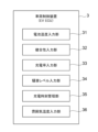
- FIG. 2 is a block diagram schematically showing the configuration of a control device shown in FIG. 1
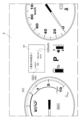
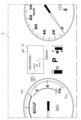
- FIG. FIG. 4 is a diagram showing an example of an image displayed on a multi-information display provided in the meter/navigator
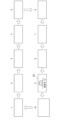
- FIG. FIG. 10 is a diagram showing an example of an operation image
- FIG. FIG. 10 is a diagram showing another example of an operation image
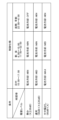
- 2 is a diagram showing an example of control specifications of the control device shown in FIG. 1
- FIG. 2 is a diagram showing an example of control specifications of the control device shown in FIG. 1
- FIG. 2 is a diagram showing an example of control specifications of the control device shown in FIG. 1
- FIG. 2 is a diagram showing an example of control specifications of the control device shown in FIG. 1
- FIG. 2 is a flowchart for explaining a control procedure of the control device shown in FIG. 1;
- the cooling device 1 is applied to an electric vehicle 100 such as a plug-in hybrid vehicle (PHEV, PHV) or an electric vehicle (EV) in which the driving battery 110 can be charged by an external power source.
- the external power supply is, for example, a power supply facility such as a quick charger or a domestic commercial power supply, but is not limited to these, and may be, for example, a power supply car.
- the cooling device 1 is a device for cooling the drive battery 110.
- the drive battery 110 is cooled during charging by an external power source (hereinafter referred to as "external charging"). Cooling.
- the cooling device 1 includes, for example, a compressor 11, a heat exchanger (condenser) 13, an expansion valve (not shown), and a heat exchanger (evaporator) 15. These compressor 11, heat exchanger 13, expansion valve and heat exchanger 15 constitute a refrigeration cycle in which refrigerant circulates.
- the compressor 11 is supplied with electricity from a driving battery 110 .
- the compressor 11 is shared with an air conditioner (not shown) and is controlled by an air conditioner control device (air conditioner ECU: Electronic Control Unit) 21 .
- air conditioner ECU Electronic Control Unit
- a radiator fan 17 is arranged to face the heat exchanger 13
- a cooling fan 19 is arranged to face the heat exchanger 15 , which are installed near the drive battery 110 .
- An auxiliary battery (not shown) is connected to the radiator fan 17 and the cooling fan 19 , and electricity is supplied to the radiator fan 17 and the cooling fan 19 from the auxiliary battery.
- the refrigerant compressed by the compressor 11 is sent to the heat exchanger 13 as a high-temperature, high-pressure refrigerant gas.
- the refrigerant gas sent to the heat exchanger 13 is cooled (liquefied) by the radiator fan 17 and sent to the expansion valve as a high-temperature, high-pressure liquid refrigerant.
- the pressure of the refrigerant liquid that has been sent to the expansion valve is rapidly lowered, and the refrigerant liquid is sent to the heat exchanger 15 as a low-temperature, low-pressure refrigerant liquid.
- the refrigerant liquid sent to the heat exchanger 15 takes heat from the surroundings of the heat exchanger 15 and evaporates.
- the surroundings of heat exchanger 15 are cooled, and driving battery 110 arranged opposite heat exchanger 15 is also cooled.
- the cooling device 1 is controlled by a vehicle control device (EVECU) 3.
- EVECU vehicle control device
- the cooling device 1 is composed of a compressor 11, a heat exchanger 13, an expansion valve (not shown) and a heat exchanger 15, an air conditioner control device 21 for controlling the compressor 11, a radiator fan 17 and a cooling fan 19 is connected to the vehicle control device 3 and controlled by the vehicle control device 3 .
- the vehicle control device 3 is connected to a driving battery control device (BMU: Battery Management Unit) 22 and a meter/navigator 23 .
- the drive battery control device 22 manages the battery temperature of the drive battery 110, the state of health (SOH) of the drive battery 110, and the state of charge (SOC) of the drive battery 110.
- the vehicle control device 3 is provided with a battery temperature input section 31 , a soundness input section 32 and a charging rate input section 33 .
- the meter/navi 23 is provided with an on/off switch 41 and a mode selection switch 43 .
- the on/off switch 41 is a switch that is operated by the user and enables the cooling device 1 to stop operating during external charging. Thus, when the on/off switch 41 is operated by the user and the on/off switch 41 is turned off, the operation of the cooling device 1 is stopped.
- the on/off switch 41 is configured with an operation image displayed on the screen of the meter/navigator 23 and is set to on by default, enabling the operation of the cooling device 1 during external charging, while turning it off. is selected to stop the operation of the cooling device 1 during external charging.
- the mode selection switch 43 is a switch that is operated by the user and enables selection of an automatic cooling mode that controls the operation of the cooling device 1 based on predetermined conditions. As a result, when the user operates the mode selection switch 43 and selects the auto cooling mode, the operation of the cooling device 1 is controlled based on the predetermined conditions.
- the mode selection switch 43 similar to the on/off switch 41, is composed of an operation image displayed on the screen of the meter/navigator 23, and is set to normal (cooling mode) by default. By selecting the automatic cooling mode while operating the device 1 normally, the operation of the cooling device 1 is controlled based on predetermined conditions.
- the on/off switch 41 and the auto cooling mode switch are displayed by selecting the "setting mode" image G1 displayed by operating the multi-information display switch provided on the meter/navigator 23.
- the on/off switch 41 is composed of an operation image G33 indicating "OFF” and “ON”, and the mode selection switch 43 becomes selectable when "ON” is selected. It is composed of an operation image G35 indicating "Normal” and "Auto”.
- the on/off switch 41 and the auto cooling mode switch may be configured with an operation image G5 indicating "OFF", "ON” and “Auto”. In this case, the operation image G53 indicating "OFF” and “ON” functions as the on/off switch 41, and the operation image G55 indicating "ON” and “Auto” functions as the mode selection switch 43. .
- a noise detection device 24 , an EV remote control device 25 , an onboard charger control device 26 and an engine control device 27 are also connected to the vehicle control device 3 .
- the vehicle control device 3 is provided with a noise level input section 34 , a charging time management section 35 and an ambient temperature input section 36 .
- the noise detection device 24 includes, for example, a microphone and detects the noise level around the electric vehicle.
- the noise level detected by the noise detection device 24 is managed by the noise level input section 34 .
- the EV remote control device 25 is set with an external charging start time and a time from the start of charging to the start of operation of the cooling device 1 by a mobile terminal such as a smartphone.
- the charging time management unit 35 manages the external charging start time set in the EV remote control device 25 and the time from the start of charging to the start of operation of the cooling device 1 .
- Connection information for a normal charging gun (not shown) is input to the vehicle-mounted charger control device 26 .
- the connection information of the normal charging gun input to the vehicle-mounted charger control device 26 is managed by the charging time management unit 35 .
- the intake air temperature (outside air temperature around the vehicle) is input to the engine control device 27 .
- the intake air temperature input to the engine control device 27 is managed by the atmosphere temperature input unit 36 as the outside air temperature around the vehicle.
- the above-described vehicle control device 3 includes, for example, a processor (not shown) composed of an arithmetic unit, registers for storing instructions and information, peripheral circuits, etc., ROM (Read Only Memory), RAM (Random Access Memory), etc. It is composed of a memory (not shown) and an input/output interface (not shown).
- a processor (not shown) composed of an arithmetic unit, registers for storing instructions and information, peripheral circuits, etc., ROM (Read Only Memory), RAM (Random Access Memory), etc. It is composed of a memory (not shown) and an input/output interface (not shown).
- the vehicle control device 3 stops the operation of the cooling device 1 when the on/off switch 41 is turned off during external charging.
- External charging in which the operation of the cooling device 1 is stopped is, for example, normal charging from a commercial power supply for home use.
- the power supply current is alternating current, charging via an in-vehicle charger, and charging at a much lower voltage than quick charging. is distinguished from fast charging by
- the vehicle control device 3 controls the operation of the cooling device 1 during external charging based on predetermined conditions. do.
- the operation of the cooling device 1 can be controlled during external charging under the user's desired conditions by appropriately setting the predetermined conditions by the user or the automobile manufacturer.
- the vehicle control device 3 controls the noise level input to the noise level input unit 34 or the charging
- the operation of the cooling device 1 is controlled during external charging based on at least one of the time periods managed by the time management unit 35 and including the time during external charging.
- the control specification (battery cooling level) is set based on the noise level input from the noise level input unit 34 and the external charging time managed by the charging time management unit 35, and the control The cooling device 1 is controlled based on the specifications.
- the vehicle control device 3 controls the operation of the cooling device 1 so as to achieve battery cooling levels classified by noise level and time zone.
- the operation of the cooling device 1 is stopped at night or early in the morning when the noise level is low. In this way, the operating sound (noise) of the cooling device 1 can be reduced at night or early in the morning when the noise level is low.
- the vehicle control device 3 when the on/off switch 41 is turned on and the auto cooling mode is selected, the battery temperature input from the battery temperature input unit 31, Alternatively, the operation of the cooling device 1 is controlled during external charging based on at least one of the outside air temperature around the vehicle managed by the ambient temperature input unit 36 .
- the control specification (battery cooling level) is set based on the outside air temperature around the vehicle managed by the ambient temperature input unit 36, and the cooling device 1 is operated during external charging based on the control specification. Operation is controlled.
- the vehicle control device 3 controls the cooling device 1 so as to achieve battery cooling levels classified by the outside air temperature around the vehicle.
- cooling device 1 For example, the higher the ambient temperature of drive battery 110, the lower the cooling efficiency of drive battery 110. Therefore, the operation of cooling device 1 is stopped when the ambient temperature of drive battery 110 is higher than a predetermined temperature. . In this way, cooling device 1 is operated at an ambient temperature at which driving battery 110 is efficiently cooled, and driving battery 110 can be efficiently cooled.
- the vehicle control device 3 controls the drive battery input from the soundness input unit 32 when the on/off switch 41 is turned on and the auto cooling mode is selected. Based on the soundness of 110, the operation of the cooling device 1 is controlled during external charging. Health is assessed by SOH.
- the SOH is expressed as a percentage of the full charge capacity at the time of deterioration (current) with respect to the full charge capacity at the time of initial (when new).
- control specifications are set based on the SOH input from the soundness input unit 32, and the cooling device 1 is controlled based on the control specifications.
- the vehicle control device 3 controls the cooling device 1 so as to achieve battery cooling levels classified by SOH.
- the higher the soundness of the drive battery 110 the more likely the drive battery 110 is to deteriorate. In this way, the temperature of drive battery 110 approaches the target temperature, and deterioration of drive battery 110 can be suppressed.
- the operation of the cooling device 1 is started from the start of external charging input from the cooling start time input unit (not shown).
- the operation of the cooling device 1 is controlled during external charging based on the time until.
- the operation of the cooling device 1 is stopped during external charging when the outside air temperature around the vehicle is equal to or higher than a predetermined temperature. . Then, when the outside air temperature around the vehicle becomes lower than the predetermined temperature after the passage of the predetermined time, the operation of the cooling device 1 is started during the external charging. When the outside air temperature around the vehicle is equal to or higher than a predetermined temperature, the operation of the cooling device 1 is stopped. Therefore, if the predetermined temperature is set to a temperature at which the cooling efficiency of drive battery 110 is reduced, the operation of cooling device 1 is stopped in a state where the cooling efficiency of drive battery 110 is reduced.
- the operation of the cooling device 1 is stopped, and the operation of the cooling device 1 is started when the outside air temperature around the vehicle becomes lower than the predetermined temperature after a predetermined time has elapsed. Therefore, if the predetermined temperature is the temperature at which the cooling efficiency of the drive battery 110 decreases, the operation of the cooling device 1 is stopped, and after a predetermined time has passed, the cooling device 1 is cooled while the cooling efficiency of the drive battery 110 is restored. Operation is started (restarted). As a result, the cooling device 1 is operated in a state in which the cooling efficiency of the driving battery 110 is high, and the driving battery 110 can be efficiently cooled.
- the cooling time during external charging is determined based on the time from the start of operation of the cooling device 1 managed by the cooling operation time management unit.
- the operation of the cooling device 1 is controlled. For example, control is performed so that the operation of the cooling device 1 is suppressed when the time from the start of operation of the cooling device 1 becomes nighttime. As a result, the operating sound (noise) of the cooling device 1 can be reduced at night when the noise level is low.
- the cooling device during external charging is controlled based on the charging rate of the driving battery 110 input to the charging rate input unit 33 . 1 is operated and controlled.
- the charging rate is evaluated by SOC.
- the SOC is defined as 100% in a fully charged state and 0% in a fully discharged state. For example, if the cooling device 1 continues to operate with the charging rate of the drive battery 110 approaching 100%, it will take time for the drive battery 110 to become fully charged. When it approaches 100%, the operation of the cooling device 1 is stopped.
- the vehicle control device 3 starts normal charging when the normal charging start condition is satisfied in the high voltage start mode (step S1: Yes, step S2).
- the normal charging start condition is, for example, connection of a normal charging connector (normal charging gun) to the normal charging port, and when the normal charging connector is connected to the normal charging port, the vehicle control device 3 starts normal charging. .
- step S1: No the vehicle control device 3 enters a standby state.
- the vehicle control device 3 determines whether or not conditions for starting the auto cooling mode are satisfied (step S3).
- Conditions for starting the auto cooling mode are, for example, that the on/off switch 41 is not turned off, and that the battery temperature of the driving battery 110 input to the battery temperature input unit 31 is a predetermined temperature (eg, 27° C.) or higher. and that the battery is being charged normally.
- step S3 When the auto cooling mode start condition is satisfied (step S3: Yes), the vehicle control device 3 controls the operation of the cooling device 1 based on a predetermined condition (step S4). After starting the operation control of the cooling device 1 based on a predetermined condition, the vehicle control device 3 determines whether or not a condition for terminating battery cooling is satisfied (step S5).
- the conditions for terminating battery cooling are, for example, that normal charging is not in progress, and that the battery temperature of drive battery 110 input to battery temperature input unit 31 is equal to or lower than a predetermined temperature (for example, 22° C.), or that charging That is, the rate is equal to or higher than a predetermined value (eg, 95%).
- step S5 When the condition for terminating battery cooling is satisfied (step S5: Yes), the vehicle control device 3 terminates battery cooling (step S6). If the condition for terminating battery cooling is not satisfied (step S5: No), the vehicle control device continues the operation control of the cooling device 1.
- the vehicle control device 3 determines whether or not the normal charging end condition is satisfied (step S7).
- the normal charging end condition is, for example, disconnection of the normal charging connector (normal charging gun) from the normal charging port.
- step S7: YES the vehicle control device 3 terminates normal charging (step S8). If the normal charging end condition is not satisfied (step S7: No), the vehicle control device 3 returns to step S3 and repeats determination of the auto cooling mode start condition. If the conditions for starting the auto cooling mode are not satisfied (step S3: No), the vehicle control device 3 proceeds to step S7 to determine the conditions for ending normal charging.
- the control device (vehicle control device 3) of the cooling device 1 when the on/off switch 41 is turned on and the auto cooling mode is selected by the mode selection switch 43, the predetermined The operation of the cooling device 1 is controlled during external charging based on the conditions. As a result, the operation of the cooling device 1 can be controlled under the conditions required by the user by appropriately setting the predetermined conditions by the user or the automobile manufacturer.
- the present invention is not limited to the above-described embodiments, and includes modifications of the above-described embodiments and modes in which these modes are combined as appropriate.
- cooling device 11 compressor 13 heat exchanger (condenser) 15 heat exchanger (evaporator) 17 radiator fan 19 cooling fan 21 air conditioner control device (air conditioner ECU) 22 drive battery control unit (BMU) 23 meter/navi 24 noise detection device 25 EV remote control device 26 vehicle charger control device 27 engine control device 3 vehicle control device (EVECU) (operation control device for cooling device) 31 battery temperature input section 32 soundness input section 33 charging rate input section 34 noise level input section 35 charging time management section 36 ambient temperature input section 41 on/off switch 43 mode selection switch 5 multi-information display 51 multi-information display switch G1 " Setting mode" image G33 Operation image G35 indicating "OFF” and “ON” Operation image G5 indicating "Normal” and “Auto” Operation image G53 indicating “OFF”, “ON” and “Auto” Operation image operation image G55 indicating "ON” and “Auto” Operation image 100 indicating “ON” and “Auto” Electric vehicle 110 Drive battery
Landscapes
- Engineering & Computer Science (AREA)
- Transportation (AREA)
- Mechanical Engineering (AREA)
- Power Engineering (AREA)
- Life Sciences & Earth Sciences (AREA)
- Sustainable Development (AREA)
- Sustainable Energy (AREA)
- Chemical & Material Sciences (AREA)
- Combustion & Propulsion (AREA)
- Electric Propulsion And Braking For Vehicles (AREA)
- Charge And Discharge Circuits For Batteries Or The Like (AREA)
Abstract
冷却装置(1)の運転制御装置(3)は、所定電動車両(100)以外の給電設備からの外部充電が可能な前記所定電動車両に搭載され、外部充電中に駆動用バッテリ(110)を冷却する冷却装置の運転制御装置であって、ユーザによって操作され、前記外部充電中に前記冷却装置の運転停止を可能にするオン・オフスイッチ(41)と、予め定められた条件に基づいて前記冷却装置を運転制御するオート冷却モードの選択を可能にするモード選択スイッチ(43)と、を備える。
Description
本開示は、冷却装置の運転制御装置に関する。
特許文献1には、外部電源により車載バッテリを充電する場合に、車載バッテリを冷却する冷却装置が開示されている。かかる冷却装置の運転制御装置は、充電地点の位置情報に基づいて充電地点の静寂性要求度を判定する判定部と、空調装置に対し、静寂性要求度が所定値以上の充電地点で充電する場合の空調装置(電動コンプレッサ)の回転数の上限値を、静寂性要求度が所定値未満の充電地点で充電する場合の空調装置(電動コンプレッサ)の回転数の上限値よりも低く設定する制御部と、を備えている。
かかる冷却装置の運転制御装置によれば、静寂性要求度が所定値以上の充電地点で充電する場合の空調装置(電動コンプレッサ)の作動音が、静寂性要求度が所定値未満の充電地点で充電する場合の空調装置(電動コンプレッサ)の作動音よりも小さくなり、周囲の不快感を抑制できる。
特許文献1が開示する冷却装置の運転制御装置では、外部充電中に冷却装置の運転を停止できない。
上述の事情に鑑みて、本発明の少なくとも一実施形態は、外部充電中に冷却装置の運転を停止できる冷却装置の制御装置を提供することを目的とする。
(1)本発明の少なくとも一実施形態に係る冷却装置の運転制御装置は、所定電動車両以外の給電設備からの外部充電が可能な前記所定電動車両に搭載され、外部充電中に駆動用バッテリを冷却する冷却装置の運転制御装置であって、ユーザによって操作され、前記外部充電中に前記冷却装置の運転停止を可能にするオン・オフスイッチと、予め定められた条件に基づいて前記冷却装置を運転制御するオート冷却モードの選択を可能にするモード選択スイッチと、を備える。
上記(1)の構成によれば、オン・オフスイッチがオフされた場合に、冷却装置の運転が停止される。また、オン・オフスイッチがオンされ、かつ、モード選択スイッチによってオート冷却モードが選択された場合に、予め定めた条件に基づいて冷却装置が運転制御される。これにより、予め定める条件をユーザ又は自動車メーカが適宜設定することにより、ユーザが求める条件で冷却装置を運転制御できる。
(2)幾つかの実施形態では、上記(1)の構成において、前記外部充電は、家庭用の商用電源から充電される普通充電である。
上記(2)の構成によれば、時間をかけて充電するため、バッテリへの負荷が小さく、冷却装置を停止することができるため、冷却装置による騒音や振動など、車両周辺の環境への影響を抑制することができる。
(3)幾つかの実施形態では、上記(1)又は(2)の構成において、前記モード選択スイッチは、前記オン・オフスイッチがオンされた場合に、前記オート冷却モードの選択を可能にする。
上記(3)の構成によれば、オン・オフスイッチがオンされた後に、オート冷却モードの選択が可能になるので、オン・オフスイッチがオフされた状態でオート冷却モードが選択されるのを防止できる。
(4)幾つかの実施形態では、上記(1)から(3)のいずれか一つの構成において、前記所定電動車両に設けられた騒音検出装置から騒音レベルが入力される騒音レベル入力部と、外部充電時の時刻を管理する充電時刻管理部と、を備え、前記オート冷却モードが選択された場合に、前記騒音レベル入力部から入力された騒音レベル、又は前記充電時刻管理部で管理される前記外部充電時の時刻が含まれる時間帯の少なくとも一方に基づいて、前記冷却装置を運転制御する。
上記(4)の構成によれば、騒音レベル又は時間帯のすくなくとも一方に基づいて冷却装置が運転制御される。例えば、騒音レベルが低い夜間や早朝に冷却装置の運転が停止される。これにより、騒音レベルが低い夜間や早朝において冷却装置の作動音(騒音)を低減できる。
(5)幾つかの実施形態では、上記(1)から(4)のいずれか一つの構成において、前記所定電動車両に設けられたバッテリ制御装置から前記駆動用バッテリの電池温度が入力される電池温度入力部と、車両周りの外気温度が入力される雰囲気温度入力部と、を備え、前記オート冷却モードが選択された場合に、前記電池温度入力部から入力された電池温度、又は、前記雰囲気温度入力部に入力された前記外気温度の少なくとも一方に基づいて、前記冷却装置を運転制御する。
上記(5)の構成によれば、駆動用バッテリの電池温度又は車両周りの外気温度の少なくとも一方に基づいて冷却装置が運転制御される。例えば、車両周りの外気温度が高いほど駆動用バッテリの冷却効率が低下するので、車両周りの外気温度が予め定めた温度よりも低い場合に冷却装置の冷却効果が高められる。これにより、駆動用バッテリの冷却効率が高い外気温度で冷却装置の冷却効果が高められ、駆動用バッテリを効率的に冷却できる。
(6)幾つかの実施形態では、上記(1)から(5)のいずれか一つの構成において、前記所定電動車両に設けられたバッテリ制御装置から前記駆動用バッテリの健全性が入力される健全性入力部を備え、前記オート冷却モードが選択された場合に、前記健全性入力部から入力された前記駆動用バッテリの健全性に基づいて、前記冷却装置を運転制御する。
上記(6)の構成によれば、駆動用バッテリの健全性に基づいて冷却装置が運転制御される。例えば、駆動用バッテリの健全性が高いほど駆動用バッテリが劣化しやすいため、駆動用バッテリの健全性が高いほど目標温度に近づくように冷却装置が運転制御される。これにより、駆動用バッテリの温度が目標温度に近づき、駆動用バッテリの劣化を抑制できる。
(7)幾つかの実施形態では、上記(1)から(6)のいずれか一つの構成において、前記冷却装置は、前記所定電動車両の車両周りの外気を取り込んで前記駆動用バッテリを空冷する冷却ファンを備え、前記オート冷却モードが選択された場合に、車両周りの外気温度が所定温度以上のときは、前記冷却装置の運転を停止し、所定時間経過後、前記車両周りの外気温度が前記所定温度未満となったときに、前記冷却装置の運転を開始する。
上記(7)の構成によれば、車両周りの外気温度が所定温度以上のときは、冷却装置の運転が停止される。よって、所定温度を駆動用バッテリの冷却効率が低下する温度とすれば、駆動用バッテリの冷却効率が低下した状態で冷却装置の運転が停止される。一方、冷却装置の運転を停止し、所定時間経過後、車両周りの外気温度が所定温度未満となったときに、冷却装置の運転が開始される。よって、所定温度を駆動用バッテリの冷却効率が低下する温度とすれば、冷却装置の運転を停止し、所定時間経過後、駆動用バッテリの冷却効率が復帰した状態で冷却装置の運転が開始(再開)される。これにより、駆動用バッテリの冷却効率が高い状態で冷却装置が運転され、駆動用バッテリを効率的に冷却できる。
(8)幾つかの実施形態では、上記(1)から(7)のいずれか一つの構成において、前記冷却装置の運転開始からの時間を管理する冷却運転時間管理部を備え、前記オート冷却モードが選択された場合に、前記冷却運転時間管理部が管理する前記冷却装置の運転開始からの時間に基づいて、前記冷却装置を運転制御する。
上記(8)の構成によれば、冷却装置の運転開始からの時間に基づいて冷却装置が運転制御される。例えば、冷却装置の運転開始からの時間が夜間になると冷却装置の運転が抑制されるように制御される。これにより、騒音レベルが低い夜間において冷却装置の作動音(騒音)を低減できる。
(9)幾つかの実施形態では、上記(1)から(8)のいずれか一つの構成において、前記所定電動車両に設けられたバッテリ制御装置から前記駆動用バッテリの充電率が入力される充電率入力部を備え、前記オート冷却モードが選択された場合に、前記充電率入力部に入力される前記駆動用バッテリの充電率に基づいて、前記冷却装置を運転制御する。
上記(9)の構成によれば、駆動用バッテリの充電率に基づいて冷却装置が運転制御される。例えば、駆動用バッテリの充電率が100%に近づいた状態で冷却装置の運転が継続されると駆動用バッテリが満充電になるまで時間がかかるので、駆動用バッテリの充電率が100%に近づくと冷却装置の運転が停止される。
本発明の少なくとも一実施形態によれば、外部充電中に冷却装置の運転を停止できる。
以下、添付図面を参照して本発明の幾つかの実施形態について説明する。ただし、実施形態として記載されている又は図面に示されている構成部品の寸法、材質、形状、その相対的配置等は、本発明の範囲をこれに限定する趣旨ではなく、単なる説明例にすぎない。
実施形態にかかる冷却装置1は、外部電源によって駆動用バッテリ110を充電できるプラグインハイブリッド自動車(PHEV,PHV)や電気自動車(EV)等の電動車両100に適用される。外部電源は、例えば、急速充電器、家庭用の商用電源等の給電設備であるが、これらに限られるものではなく、例えば、電源車であってもよい。
図1に示すように、実施形態に係る冷却装置1は、駆動用バッテリ110を冷却するための装置であり、例えば、外部電源による充電(以下「外部充電」という)中に駆動用バッテリ110を冷却する。実施形態に係る冷却装置1は、例えば、コンプレッサ11、熱交換器(コンデンサ)13、エキスパンションバルブ(図示せず)及び熱交換器(エバポレータ)15によって構成される。これらコンプレッサ11、熱交換器13、エキスパンションバルブ及び熱交換器15は、冷媒が循環する冷凍サイクルを構成する。本実施形態では、コンプレッサ11は駆動用バッテリ110から電気が供給される。また、コンプレッサ11はエアコン(図示せず)と共用され、エアコン制御装置(エアコンECU:Electronic Control Unit)21によって制御される。また、熱交換器13にはラジエータファン17が対向配置され、熱交換器15には冷却ファン19が対向配置され、駆動用バッテリ110の近傍に設置される。ラジエータファン17及び冷却ファン19には補機バッテリ(図示せず)が接続され、補機バッテリからラジエータファン17及び冷却ファン19に電気が供給される。
そして、コンプレッサ11で圧縮された冷媒は、高温高圧の冷媒ガスとなって熱交換器13に送られる。熱交換器13に送られた冷媒ガスはラジエータファン17によって冷却(液化)され、高温高圧の液冷媒となってエキスパンションバルブに送られる。エキスパンションバルブに送られた冷媒液は急激に圧力が下がり、低温低圧の冷媒液となって熱交換器15に送られる。熱交換器15に送られた冷媒液は、熱交換器15の周囲から熱を奪い気化する。熱交換器15の周囲は冷却され、熱交換器15の近傍に対向配置された駆動用バッテリ110も冷却される。
実施形態に係る冷却装置1は、車両制御装置(EVECU)3によって制御される。例えば、冷却装置1が、コンプレッサ11、熱交換器13、エキスパンションバルブ(図示せず)及び熱交換器15で構成される場合に、コンプレッサ11を制御するエアコン制御装置21、ラジエータファン17及び冷却ファン19が車両制御装置3に接続され、車両制御装置3によって制御される。
また、車両制御装置3には、駆動用バッテリ制御装置(BMU:Battery Management Unit)22及びメータ/ナビ23が接続されている。駆動用バッテリ制御装置22では、駆動用バッテリ110の電池温度、駆動用バッテリ110の健全性(SOH:State Of Health)、及び駆動用バッテリ110の充電率(SOC:State Of Charge)が管理され、図2に示すように、車両制御装置3には、電池温度入力部31、健全性入力部32及び充電率入力部33が設けられる。
図4および図5に示すように、メータ/ナビ23には、オン・オフスイッチ41とモード選択スイッチ43とが設けられている。オン・オフスイッチ41は、ユーザによって操作され、外部充電中に冷却装置1の運転停止を可能にするスイッチである。これにより、ユーザによってオン・オフスイッチ41が操作され、オン・オフスイッチ41がオフされた場合に、冷却装置1の運転が停止される。
例えば、オン・オフスイッチ41は、メータ/ナビ23の画面に表示される操作画像で構成され、デフォルトでオンに設定されており、外部充電中に冷却装置1の運転を可能にする一方、オフを選択することで外部充電中に冷却装置1の運転を停止する。
モード選択スイッチ43は、ユーザによって操作され、予め定めた条件に基づいて冷却装置1を運転制御するオート冷却モードの選択を可能にするスイッチである。これにより、ユーザによってモード選択スイッチ43が操作され、オート冷却モードが選択された場合に、予め定めた条件に基づいて冷却装置1が運転制御される。
例えば、モード選択スイッチ43は、オン・オフスイッチ41と同様、メータ/ナビ23の画面に表示される操作画像で構成され、デフォルトでノーマル(冷却モード)に設定されており、外部充電中に冷却装置1を通常運転する一方、オート冷却モードを選択することで、予め定めた条件に基づいて冷却装置1を運転制御する。
例えば、オン・オフスイッチ41及びオート冷却モードスイッチは、メータ/ナビ23に設けられたマルチインフォメーションディスプレイスイッチを操作することで表示される「設定モード」画像G1を選択することにより表示される。例えば、図4に示すように、オン・オフスイッチ41は、「OFF」と「ON」を示す操作画像G33で構成され、モード選択スイッチ43は、「ON」を選択した場合に選択可能となる「Normal」と「Auto」を示す操作画像G35で構成される。また、例えば、図5に示すように、オン・オフスイッチ41とオート冷却モードスイッチは、「OFF」「ON」及び「Auto」を示す操作画像G5で構成されてもよい。この場合に、「OFF」と「ON」を示す操作画像G53がオン・オフスイッチ41の機能を発揮し、「ON」と「Auto」を示す操作画像G55がモード選択スイッチ43の機能を発揮する。
また、車両制御装置3には、騒音検出装置24、EVリモート制御装置25、車載充電器制御装置26及びエンジン制御装置27が接続される。車両制御装置3には、騒音レベル入力部34、充電時刻管理部35、及び雰囲気温度入力部36が設けられている。騒音検出装置24は、例えば、マイクロフォンを含み、電動車両周辺の騒音レベルを検出する。そして、騒音検出装置24で検出された騒音レベルは、騒音レベル入力部34で管理される。EVリモート制御装置25には、スマートフォン等の携帯端末によって、外部充電開始時間、及び充電開始から冷却装置1の運転開始までの時間が設定される。そして、EVリモート制御装置25に設定された外部充電開始時間、充電開始から冷却装置1の運転開始までの時間は充電時刻管理部35で管理される。車載充電器制御装置26には、普通充電ガン(図示せず)の接続情報が入力される。そして、車載充電器制御装置26に入力された普通充電ガンの接続情報は充電時刻管理部35で管理される。エンジン制御装置27には、吸気温度(車両周りの外気温度)が入力される。そして、エンジン制御装置27に入力された吸気温度は、車両周りの外気温度として雰囲気温度入力部36で管理される。
上述した車両制御装置3は、例えば、演算装置、命令や情報を格納するレジスタ、周辺回路等から構成されるプロセッサ(図示せず)、ROM(Read Only Memory)やRAM(Random Access Memory)等のメモリ(図示せず)のほか入出力インターフェース(図示せず)によって構成される。
車両制御装置3は、外部充電中に、オン・オフスイッチ41がオフされた場合に冷却装置1の運転を停止する。冷却装置1の運転が停止される外部充電は、例えば、家庭用の商用電源から充電される普通充電であり、例えば、急速充電器による急速充電の場合には冷却装置1の運転を継続する。尚、普通充電は、家庭用の商用電源から充電されることのほか、電源電流が交流であることや、車載充電器を介して充電されること、急速充電よりも遥かに小さな電圧で充電されること、によって急速充電と区別される。
車両制御装置3は、オン・オフスイッチ41がオンされ、かつ、モード選択スイッチ43によってオート冷却モードが選択された場合に、予め定められた条件に基づいて外部充電中に冷却装置1を運転制御する。これにより、予め定める条件をユーザ又は自動車メーカが適宜設定することにより、ユーザが求める条件で外部充電中に冷却装置1を運転制御できる。
例えば、図6に示すように、車両制御装置3は、オン・オフスイッチ41がオンされ、かつ、オート冷却モードが選択された場合に、騒音レベル入力部34に入力された騒音レベル、又は充電時刻管理部35で管理される外部充電時の時刻が含まれる時間帯の少なくとも一方に基づいて外部充電中に冷却装置1を運転制御する。
図6に示す例では、騒音レベル入力部34から入力された騒音レベル及び充電時刻管理部35で管理される外部充電時の時刻に基づいて制御仕様(電池冷却のレベル)が設定され、当該制御仕様に基づいて冷却装置1が制御される。例えば、騒音レベルと時間帯で区分けされた電池冷却のレベルを実現するように、車両制御装置3は冷却装置1を運転制御する。例えば、騒音レベルが低い夜間や早朝に冷却装置1の運転が停止される。このようにすれば、騒音レベルが低い夜間や早朝において冷却装置1の作動音(騒音)を低減できる。
また、例えば、図7に示すように、車両制御装置3は、オン・オフスイッチ41がオンされ、かつ、オート冷却モードが選択された場合に、電池温度入力部31から入力された電池温度、又は、雰囲気温度入力部36で管理される車両周りの外気温度の少なくとも一方に基づいて外部充電中に冷却装置1を運転制御する。
図7に示す例では、雰囲気温度入力部36で管理される車両周りの外気温度に基づいて制御仕様(電池冷却のレベル)が設定され、当該制御仕様に基づいて外部充電中に冷却装置1が運転制御される。例えば、車両周りの外気温度で区分けされた電池冷却のレベルを実現するように、車両制御装置3は冷却装置1を制御する。
例えば、駆動用バッテリ110の雰囲気温度が高いほど駆動用バッテリ110の冷却効率が低下するので、駆動用バッテリ110の雰囲気温度が予め定めた温度よりも高い場合に冷却装置1の運転が停止される。このようにすれば、駆動用バッテリ110の冷却効率が高い雰囲気温度で冷却装置1が運転され、駆動用バッテリ110を効率的に冷却できる。
また、例えば、図8に示すように、車両制御装置3は、オン・オフスイッチ41がオンされ、かつ、オート冷却モードが選択された場合に、健全性入力部32から入力された駆動用バッテリ110の健全性に基づいて外部充電中に冷却装置1を運転制御する。健全性は、SOHで評価される。尚、SOHは、初期時(新品時)の満充電容量に対する劣化時(現在)の満充電容量を百分率で表したもので示される。
図8に示す例では、健全性入力部32から入力されたSOHに基づいて制御仕様が設定され、当該制御仕様に基づいて冷却装置1が制御される。例えば、SOHで区分けされた電池冷却のレベルを実現するように、車両制御装置3は冷却装置1を制御制御する。例えば、駆動用バッテリ110の健全性が高いほど駆動用バッテリ110が劣化しやすいため、駆動用バッテリ110の健全性が高いほど目標温度に近づくように冷却装置1が運転制御される。このようにすれば、駆動用バッテリ110の温度が目標温度に近づき、駆動用バッテリ110の劣化を抑制できる。
また、例えば、オン・オフスイッチ41がオンされ、かつ、オート冷却モードが選択された場合に、冷却開始時間入力部(図示せず)から入力された外部充電の開始から冷却装置1の運転開始までの時間に基づいて外部充電中に冷却装置1を運転制御する。
また、例えば、オン・オフスイッチ41がオンされ、かつ、オート冷却モードが選択された場合に、車両周りの外気温度が所定温度以上のときは、外部充電中に冷却装置1の運転を停止する。そして、所定時間経過後、車両周りの外気温度が所定温度未満となったときに、外部充電中に冷却装置1の運転を開始する。車両周りの外気温度が所定温度以上のときは、冷却装置1の運転が停止される。よって、所定温度を駆動用バッテリ110の冷却効率が低下する温度とすれば、駆動用バッテリ110の冷却効率が低下した状態で冷却装置1の運転が停止される。一方、冷却装置1の運転を停止し、所定時間経過後、車両周りの外気温度が所定温度未満となったときに、冷却装置1の運転が開始される。よって、所定温度を駆動用バッテリ110の冷却効率が低下する温度とすれば、冷却装置1の運転を停止し、所定時間経過後、駆動用バッテリ110の冷却効率が復帰した状態で冷却装置1の運転が開始(再開)される。これにより、駆動用バッテリ110の冷却効率が高い状態で冷却装置1が運転され、駆動用バッテリ110を効率的に冷却できる。
また、例えば、オン・オフスイッチ41がオンされ、かつ、オート冷却モードが選択された場合に、冷却運転時間管理部が管理する冷却装置1の運転開始からの時間に基づいて、外部充電中に冷却装置1を運転制御する。例えば、冷却装置1の運転開始からの時間が夜間になると冷却装置1の運転が抑制されるように制御される。これにより、騒音レベルが低い夜間において冷却装置1の作動音(騒音)を低減できる。
また、例えば、オン・オフスイッチ41がオンされ、かつ、オート冷却モードが選択された場合に、充電率入力部33に入力される駆動用バッテリ110の充電率に基づいて外部充電中に冷却装置1を運転制御する。充電率は、SOCで評価される。尚、SOCは、満充電状態を100%、完全放電状態を0%とする。例えば、駆動用バッテリ110の充電率が100%に近づいた状態で冷却装置1の運転が継続されると駆動用バッテリ110が満充電になるまで時間がかかるので、駆動用バッテリ110の充電率が100%に近づくと冷却装置1の運転が停止される。
図9に示すように、車両制御装置3は、高電圧開始モードにおいて、普通充電開始条件が成立すると普通充電が開始される(ステップS1:Yes,ステップS2)。普通充電開始条件は、例えば、普通充電口への普通充電コネクタ(普通充電ガン)の接続であり、普通充電口に普通充電コネクタが接続されると、車両制御装置3が、普通充電を開始する。普通充電開始条件が成立しない場合には(ステップS1:No)、車両制御装置3は、待機状態となる。
車両制御装置3は、普通充電を開始すると、オート冷却モードの開始条件が成立しているか否かを判定する(ステップS3)。オート冷却モードの開始条件は、例えば、オン・オフスイッチ41がオフされていないこと、電池温度入力部31に入力された駆動用バッテリ110の電池温度が所定温度(例えば27°C)以上であること、及び、普通充電中であること、である。
車両制御装置3は、オート冷却モード開始条件が成立すると(ステップS3:Yes)、予め定められた条件に基づいて冷却装置1を運転制御する(ステップS4)。車両制御装置3は、予め定められた条件に基づいて冷却装置1の運転制御を開始すると、電池冷却の終了条件が成立しているか否かを判定する(ステップS5)。電池冷却の終了条件は、例えば、普通充電中でないこと、及び、電池温度入力部31に入力された駆動用バッテリ110の電池温度が所定温度(例えば22°C)以下であること、又は、充電率が所定値(例えば95%)以上であること、である。車両制御装置3は、電池冷却の終了条件が成立すると(ステップS5:Yes)、電池冷却を終了する(ステップS6)。電池冷却の終了条件が成立しない場合は(ステップS5:No)、車両制御装置は冷却装置1の運転制御を継続する。
車両制御装置3は、電池冷却を終了すると、普通充電終了条件が成立しているか否かを判定する(ステップS7)。普通充電終了条件は、例えば、普通充電口から普通充電コネクタ(普通充電ガン)の接続解除である。普通充電口から普通充電コネクタが取り外されると(ステップS7:YES)、車両制御装置3が、普通充電を終了する(ステップS8)。普通充電終了条件が成立しない場合は、(ステップS7:No)、車両制御装置3は、ステップS3へ戻り、オート冷却モードの開始条件の判定を繰り返す。また、オート冷却モードの開始条件が成立しない場合は(ステップS3:No)、車両制御装置3は、ステップS7へ進み、普通充電終了条件の判定を行う。
実施形態に係る冷却装置1の制御装置(車両制御装置3)によれば、オン・オフスイッチ41がオンされ、かつ、モード選択スイッチ43によってオート冷却モードが選択された場合に、予め定められた条件に基づいて外部充電中に冷却装置1を運転制御する。これにより、予め定める条件をユーザ又は自動車メーカが適宜設定することにより、ユーザが求める条件で冷却装置1を運転制御できる。
本発明は上述した実施形態に限定されることはなく、上述した実施形態に変形を加えた形態や、これらの形態を適宜組み合わせた形態も含む。
以上、図面を参照しながら各種の実施の形態について説明したが、本発明はかかる例に限定されないことは言うまでもない。当業者であれば、特許請求の範囲に記載された範疇内において、各種の変更例又は修正例に想到し得ることは明らかであり、それらについても当然に本発明の技術的範囲に属するものと了解される。また、発明の趣旨を逸脱しない範囲において、上記実施の形態における各構成要素を任意に組み合わせてもよい。
なお、本出願は、2021年11月22日出願の日本特許出願(特願2021-189448)に基づくものであり、その内容は本出願の中に参照として援用される。
1 冷却装置
11 コンプレッサ
13 熱交換器(コンデンサ)
15 熱交換器(エバポレータ)
17 ラジエータファン
19 冷却ファン
21 エアコン制御装置(エアコンECU)
22 駆動用バッテリ制御装置(BMU)
23 メータ/ナビ
24 騒音検出装置
25 EVリモート制御装置
26 車載充電器制御装置
27 エンジン制御装置
3 車両制御装置(EVECU)(冷却装置の運転制御装置)
31 電池温度入力部
32 健全性入力部
33 充電率入力部
34 騒音レベル入力部
35 充電時刻管理部
36 雰囲気温度入力部
41 オン・オフスイッチ
43 モード選択スイッチ
5 マルチインフォメーションディスプレイ
51 マルチインフォメーションディスプレイスイッチ
G1 「設定モード」画像
G33 「OFF」と「ON」を示す操作画像
G35 「Normal」と「Auto」を示す操作画像
G5 「OFF」「ON」及び「Auto」を示す操作画像
G53 「OFF」と「ON」を示す操作画像操作画像
G55 「ON」と「Auto」を示す操作画像
100 電動車両
110 駆動用バッテリ
11 コンプレッサ
13 熱交換器(コンデンサ)
15 熱交換器(エバポレータ)
17 ラジエータファン
19 冷却ファン
21 エアコン制御装置(エアコンECU)
22 駆動用バッテリ制御装置(BMU)
23 メータ/ナビ
24 騒音検出装置
25 EVリモート制御装置
26 車載充電器制御装置
27 エンジン制御装置
3 車両制御装置(EVECU)(冷却装置の運転制御装置)
31 電池温度入力部
32 健全性入力部
33 充電率入力部
34 騒音レベル入力部
35 充電時刻管理部
36 雰囲気温度入力部
41 オン・オフスイッチ
43 モード選択スイッチ
5 マルチインフォメーションディスプレイ
51 マルチインフォメーションディスプレイスイッチ
G1 「設定モード」画像
G33 「OFF」と「ON」を示す操作画像
G35 「Normal」と「Auto」を示す操作画像
G5 「OFF」「ON」及び「Auto」を示す操作画像
G53 「OFF」と「ON」を示す操作画像操作画像
G55 「ON」と「Auto」を示す操作画像
100 電動車両
110 駆動用バッテリ
Claims (9)
- 所定電動車両以外の給電設備からの外部充電が可能な前記所定電動車両に搭載され、外部充電中に駆動用バッテリを冷却する冷却装置の運転制御装置であって、
ユーザによって操作され、前記外部充電中に前記冷却装置の運転停止を可能にするオン・オフスイッチと、
予め定められた条件に基づいて前記冷却装置を運転制御するオート冷却モードの選択を可能にするモード選択スイッチと、
を備える、冷却装置の運転制御装置。 - 前記外部充電は、家庭用の商用電源から充電される普通充電である、
請求項1に記載の冷却装置の運転制御装置。 - 前記モード選択スイッチは、前記オン・オフスイッチがオンされた場合に、前記オート冷却モードの選択を可能にする、
請求項1又は2に記載の冷却装置の運転制御装置。 - 前記所定電動車両に設けられた騒音検出装置から騒音レベルが入力される騒音レベル入力部と、
外部充電時の時刻を管理する充電時刻管理部と、
を備え、
前記オート冷却モードが選択された場合に、前記騒音レベル入力部から入力された騒音レベル、又は前記充電時刻管理部で管理される前記外部充電時の時刻が含まれる時間帯の少なくとも一方に基づいて、前記冷却装置を運転制御する、請求項1から3のいずれか一項に記載の冷却装置の運転制御装置。 - 前記所定電動車両に設けられたバッテリ制御装置から前記駆動用バッテリの電池温度が入力される電池温度入力部と、
車両周りの外気温度が入力される雰囲気温度入力部と、
を備え、
前記オート冷却モードが選択された場合に、前記電池温度入力部から入力された電池温度、又は、前記雰囲気温度入力部に入力された前記外気温度の少なくとも一方に基づいて、前記冷却装置を運転制御する、請求項1から4のいずれか一項に記載の冷却装置の運転制御装置。 - 前記所定電動車両に設けられたバッテリ制御装置から前記駆動用バッテリの健全性が入力される健全性入力部を備え、
前記オート冷却モードが選択された場合に、前記健全性入力部から入力された前記駆動用バッテリの健全性に基づいて、前記冷却装置を運転制御する、請求項1から5のいずれか一項に記載の冷却装置の運転制御装置。 - 前記冷却装置は、前記所定電動車両の車両周りの外気を取り込んで前記駆動用バッテリを空冷する冷却ファンを備え、
前記オート冷却モードが選択された場合に、車両周りの外気温度が所定温度以上のときは、前記冷却装置の運転を停止し、
所定時間経過後、前記車両周りの外気温度が前記所定温度未満となったときに、前記冷却装置の運転を開始する、
請求項1から6のいずれか一項に記載の冷却装置の運転制御装置。 - 前記冷却装置の運転開始からの時間を管理する冷却運転時間管理部を備え、
前記オート冷却モードが選択された場合に、前記冷却運転時間管理部が管理する前記冷却装置の運転開始からの時間に基づいて、前記冷却装置を運転制御する、請求項1から7のいずれか一項に記載の冷却装置の運転制御装置。 - 前記所定電動車両に設けられたバッテリ制御装置から前記駆動用バッテリの充電率が入力される充電率入力部を備え、
前記オート冷却モードが選択された場合に、前記充電率入力部に入力される前記駆動用バッテリの充電率に基づいて、前記冷却装置を運転制御する、請求項1から8のいずれか一項に記載の冷却装置の運転制御装置。
Priority Applications (1)
| Application Number | Priority Date | Filing Date | Title |
|---|---|---|---|
| JP2023562129A JP7473090B2 (ja) | 2021-11-22 | 2022-08-01 | 冷却装置の運転制御装置 |
Applications Claiming Priority (2)
| Application Number | Priority Date | Filing Date | Title |
|---|---|---|---|
| JP2021-189448 | 2021-11-22 | ||
| JP2021189448 | 2021-11-22 |
Publications (1)
| Publication Number | Publication Date |
|---|---|
| WO2023089873A1 true WO2023089873A1 (ja) | 2023-05-25 |
Family
ID=86396591
Family Applications (1)
| Application Number | Title | Priority Date | Filing Date |
|---|---|---|---|
| PCT/JP2022/029425 Ceased WO2023089873A1 (ja) | 2021-11-22 | 2022-08-01 | 冷却装置の運転制御装置 |
Country Status (2)
| Country | Link |
|---|---|
| JP (1) | JP7473090B2 (ja) |
| WO (1) | WO2023089873A1 (ja) |
Citations (7)
| Publication number | Priority date | Publication date | Assignee | Title |
|---|---|---|---|---|
| JP2005137091A (ja) * | 2003-10-29 | 2005-05-26 | Toyota Motor Corp | 二次電池の制御装置および制御方法 |
| JP2007196876A (ja) * | 2006-01-27 | 2007-08-09 | Toyota Motor Corp | 電池冷却制御 |
| JP2010161904A (ja) * | 2009-01-09 | 2010-07-22 | Toyota Motor Corp | 冷却ファンの駆動制御装置 |
| JP2014018002A (ja) * | 2012-07-10 | 2014-01-30 | Omron Automotive Electronics Co Ltd | 充電装置 |
| JP2014148245A (ja) * | 2013-02-01 | 2014-08-21 | Suzuki Motor Corp | バッテリ冷却装置 |
| JP2017004849A (ja) * | 2015-06-12 | 2017-01-05 | 富士重工業株式会社 | 車載二次電池の冷却装置 |
| JP2019110044A (ja) * | 2017-12-19 | 2019-07-04 | トヨタ自動車株式会社 | 車両 |
Family Cites Families (1)
| Publication number | Priority date | Publication date | Assignee | Title |
|---|---|---|---|---|
| JP2009038958A (ja) | 2007-07-10 | 2009-02-19 | Toyota Motor Corp | 車両の制御装置および制御方法 |
-
2022
- 2022-08-01 JP JP2023562129A patent/JP7473090B2/ja active Active
- 2022-08-01 WO PCT/JP2022/029425 patent/WO2023089873A1/ja not_active Ceased
Patent Citations (7)
| Publication number | Priority date | Publication date | Assignee | Title |
|---|---|---|---|---|
| JP2005137091A (ja) * | 2003-10-29 | 2005-05-26 | Toyota Motor Corp | 二次電池の制御装置および制御方法 |
| JP2007196876A (ja) * | 2006-01-27 | 2007-08-09 | Toyota Motor Corp | 電池冷却制御 |
| JP2010161904A (ja) * | 2009-01-09 | 2010-07-22 | Toyota Motor Corp | 冷却ファンの駆動制御装置 |
| JP2014018002A (ja) * | 2012-07-10 | 2014-01-30 | Omron Automotive Electronics Co Ltd | 充電装置 |
| JP2014148245A (ja) * | 2013-02-01 | 2014-08-21 | Suzuki Motor Corp | バッテリ冷却装置 |
| JP2017004849A (ja) * | 2015-06-12 | 2017-01-05 | 富士重工業株式会社 | 車載二次電池の冷却装置 |
| JP2019110044A (ja) * | 2017-12-19 | 2019-07-04 | トヨタ自動車株式会社 | 車両 |
Also Published As
| Publication number | Publication date |
|---|---|
| JPWO2023089873A1 (ja) | 2023-05-25 |
| JP7473090B2 (ja) | 2024-04-23 |
Similar Documents
| Publication | Publication Date | Title |
|---|---|---|
| JP3711445B2 (ja) | 車両用空調充電制御装置および車載電池の充電管理装置 | |
| JP4915969B2 (ja) | バッテリパック温度最適化制御システム | |
| US9770961B2 (en) | Intermittent operation of battery temperature control system | |
| JP5488578B2 (ja) | 車両用電動冷凍サイクル装置 | |
| JPH11304327A (ja) | 車両用冷凍冷蔵装置 | |
| JP2004026077A (ja) | 車両用空調装置 | |
| JP5393503B2 (ja) | 車両用空気調和システム、及び、その運転制御方法 | |
| JP5417876B2 (ja) | 冷凍装置 | |
| CN109760488B (zh) | 汽车 | |
| JP5505236B2 (ja) | 車両用空調装置 | |
| US7240653B2 (en) | System for assisting a main engine start-up | |
| WO2023089873A1 (ja) | 冷却装置の運転制御装置 | |
| US9964319B2 (en) | Air conditioner and method for controlling an air conditioner | |
| KR20140087960A (ko) | 차량용 냉각장치 | |
| JP2021040378A (ja) | 電池出力制御装置 | |
| JP2020106204A (ja) | 車載用冷凍装置 | |
| JP2010049917A (ja) | 鉛蓄電池の電解液残量監視装置 | |
| KR102473721B1 (ko) | 차량용 무시동 에어컨 작동 제어 및 압축 구동 장치 | |
| JP2009264678A (ja) | 空調装置及び空調装置の点検方法 | |
| JP7559453B2 (ja) | 電池パックの冷却制御装置 | |
| JP7135822B2 (ja) | 車載用冷凍装置 | |
| CN114083956A (zh) | 一种控制方法、装置、设备及存储介质 | |
| KR102743113B1 (ko) | Dc 냉난방 장치가 구비된 차량 | |
| KR102843126B1 (ko) | 전동압축기 제어시스템 및 그 방법 | |
| KR20120076407A (ko) | 차량용 공조시스템의 제어 방법 |
Legal Events
| Date | Code | Title | Description |
|---|---|---|---|
| 121 | Ep: the epo has been informed by wipo that ep was designated in this application |
Ref document number: 22893979 Country of ref document: EP Kind code of ref document: A1 |
|
| WWE | Wipo information: entry into national phase |
Ref document number: 2023562129 Country of ref document: JP |
|
| NENP | Non-entry into the national phase |
Ref country code: DE |
|
| 122 | Ep: pct application non-entry in european phase |
Ref document number: 22893979 Country of ref document: EP Kind code of ref document: A1 |