WO2023084848A1 - モニタユニットおよび光モジュール - Google Patents
モニタユニットおよび光モジュール Download PDFInfo
- Publication number
- WO2023084848A1 WO2023084848A1 PCT/JP2022/027836 JP2022027836W WO2023084848A1 WO 2023084848 A1 WO2023084848 A1 WO 2023084848A1 JP 2022027836 W JP2022027836 W JP 2022027836W WO 2023084848 A1 WO2023084848 A1 WO 2023084848A1
- Authority
- WO
- WIPO (PCT)
- Prior art keywords
- light
- wall portion
- optical module
- laser
- end wall
- Prior art date
- Legal status (The legal status is an assumption and is not a legal conclusion. Google has not performed a legal analysis and makes no representation as to the accuracy of the status listed.)
- Ceased
Links
Images


Classifications
-
- H—ELECTRICITY
- H01—ELECTRIC ELEMENTS
- H01S—DEVICES USING THE PROCESS OF LIGHT AMPLIFICATION BY STIMULATED EMISSION OF RADIATION [LASER] TO AMPLIFY OR GENERATE LIGHT; DEVICES USING STIMULATED EMISSION OF ELECTROMAGNETIC RADIATION IN WAVE RANGES OTHER THAN OPTICAL
- H01S5/00—Semiconductor lasers
- H01S5/02—Structural details or components not essential to laser action
- H01S5/022—Mountings; Housings
- H01S5/02208—Mountings; Housings characterised by the shape of the housings
- H01S5/02212—Can-type, e.g. TO-CAN housings with emission along or parallel to symmetry axis
-
- G—PHYSICS
- G02—OPTICS
- G02B—OPTICAL ELEMENTS, SYSTEMS OR APPARATUS
- G02B6/00—Light guides; Structural details of arrangements comprising light guides and other optical elements, e.g. couplings
- G02B6/24—Coupling light guides
- G02B6/42—Coupling light guides with opto-electronic elements
-
- H—ELECTRICITY
- H01—ELECTRIC ELEMENTS
- H01S—DEVICES USING THE PROCESS OF LIGHT AMPLIFICATION BY STIMULATED EMISSION OF RADIATION [LASER] TO AMPLIFY OR GENERATE LIGHT; DEVICES USING STIMULATED EMISSION OF ELECTROMAGNETIC RADIATION IN WAVE RANGES OTHER THAN OPTICAL
- H01S5/00—Semiconductor lasers
- H01S5/02—Structural details or components not essential to laser action
- H01S5/022—Mountings; Housings
- H01S5/0225—Out-coupling of light
- H01S5/02251—Out-coupling of light using optical fibres
-
- H—ELECTRICITY
- H01—ELECTRIC ELEMENTS
- H01S—DEVICES USING THE PROCESS OF LIGHT AMPLIFICATION BY STIMULATED EMISSION OF RADIATION [LASER] TO AMPLIFY OR GENERATE LIGHT; DEVICES USING STIMULATED EMISSION OF ELECTROMAGNETIC RADIATION IN WAVE RANGES OTHER THAN OPTICAL
- H01S5/00—Semiconductor lasers
- H01S5/02—Structural details or components not essential to laser action
- H01S5/022—Mountings; Housings
- H01S5/0225—Out-coupling of light
- H01S5/02253—Out-coupling of light using lenses
-
- H—ELECTRICITY
- H01—ELECTRIC ELEMENTS
- H01S—DEVICES USING THE PROCESS OF LIGHT AMPLIFICATION BY STIMULATED EMISSION OF RADIATION [LASER] TO AMPLIFY OR GENERATE LIGHT; DEVICES USING STIMULATED EMISSION OF ELECTROMAGNETIC RADIATION IN WAVE RANGES OTHER THAN OPTICAL
- H01S5/00—Semiconductor lasers
- H01S5/02—Structural details or components not essential to laser action
- H01S5/022—Mountings; Housings
- H01S5/0225—Out-coupling of light
- H01S5/02257—Out-coupling of light using windows, e.g. specially adapted for back-reflecting light to a detector inside the housing
-
- H—ELECTRICITY
- H01—ELECTRIC ELEMENTS
- H01S—DEVICES USING THE PROCESS OF LIGHT AMPLIFICATION BY STIMULATED EMISSION OF RADIATION [LASER] TO AMPLIFY OR GENERATE LIGHT; DEVICES USING STIMULATED EMISSION OF ELECTROMAGNETIC RADIATION IN WAVE RANGES OTHER THAN OPTICAL
- H01S5/00—Semiconductor lasers
- H01S5/02—Structural details or components not essential to laser action
- H01S5/022—Mountings; Housings
- H01S5/023—Mount members, e.g. sub-mount members
- H01S5/02325—Mechanically integrated components on mount members or optical micro-benches
-
- H—ELECTRICITY
- H01—ELECTRIC ELEMENTS
- H01S—DEVICES USING THE PROCESS OF LIGHT AMPLIFICATION BY STIMULATED EMISSION OF RADIATION [LASER] TO AMPLIFY OR GENERATE LIGHT; DEVICES USING STIMULATED EMISSION OF ELECTROMAGNETIC RADIATION IN WAVE RANGES OTHER THAN OPTICAL
- H01S5/00—Semiconductor lasers
- H01S5/02—Structural details or components not essential to laser action
- H01S5/022—Mountings; Housings
- H01S5/0239—Combinations of electrical or optical elements
-
- H—ELECTRICITY
- H01—ELECTRIC ELEMENTS
- H01S—DEVICES USING THE PROCESS OF LIGHT AMPLIFICATION BY STIMULATED EMISSION OF RADIATION [LASER] TO AMPLIFY OR GENERATE LIGHT; DEVICES USING STIMULATED EMISSION OF ELECTROMAGNETIC RADIATION IN WAVE RANGES OTHER THAN OPTICAL
- H01S5/00—Semiconductor lasers
- H01S5/06—Arrangements for controlling the laser output parameters, e.g. by operating on the active medium
- H01S5/068—Stabilisation of laser output parameters
- H01S5/0683—Stabilisation of laser output parameters by monitoring the optical output parameters
-
- H—ELECTRICITY
- H01—ELECTRIC ELEMENTS
- H01S—DEVICES USING THE PROCESS OF LIGHT AMPLIFICATION BY STIMULATED EMISSION OF RADIATION [LASER] TO AMPLIFY OR GENERATE LIGHT; DEVICES USING STIMULATED EMISSION OF ELECTROMAGNETIC RADIATION IN WAVE RANGES OTHER THAN OPTICAL
- H01S5/00—Semiconductor lasers
- H01S5/40—Arrangement of two or more semiconductor lasers, not provided for in groups H01S5/02 - H01S5/30
- H01S5/4012—Beam combining, e.g. by the use of fibres, gratings, polarisers, prisms
-
- H—ELECTRICITY
- H01—ELECTRIC ELEMENTS
- H01S—DEVICES USING THE PROCESS OF LIGHT AMPLIFICATION BY STIMULATED EMISSION OF RADIATION [LASER] TO AMPLIFY OR GENERATE LIGHT; DEVICES USING STIMULATED EMISSION OF ELECTROMAGNETIC RADIATION IN WAVE RANGES OTHER THAN OPTICAL
- H01S5/00—Semiconductor lasers
- H01S5/40—Arrangement of two or more semiconductor lasers, not provided for in groups H01S5/02 - H01S5/30
- H01S5/4025—Array arrangements, e.g. constituted by discrete laser diodes or laser bar
- H01S5/4087—Array arrangements, e.g. constituted by discrete laser diodes or laser bar emitting more than one wavelength
- H01S5/4093—Red, green and blue [RGB] generated directly by laser action or by a combination of laser action with nonlinear frequency conversion
-
- H—ELECTRICITY
- H10—SEMICONDUCTOR DEVICES; ELECTRIC SOLID-STATE DEVICES NOT OTHERWISE PROVIDED FOR
- H10F—INORGANIC SEMICONDUCTOR DEVICES SENSITIVE TO INFRARED RADIATION, LIGHT, ELECTROMAGNETIC RADIATION OF SHORTER WAVELENGTH OR CORPUSCULAR RADIATION
- H10F77/00—Constructional details of devices covered by this subclass
- H10F77/40—Optical elements or arrangements
Definitions
- the present disclosure relates to monitor units and optical modules.
- This application claims priority based on Japanese application No. 2021-183153 filed on November 10, 2021, and incorporates all the descriptions described in the Japanese application.
- a light source includes a semiconductor laser element such as a laser diode and a housing that accommodates the semiconductor laser element.
- a semiconductor laser device When using a semiconductor laser device, a portion of the laser light is usually monitored in order to maintain the desired output state.
- a semiconductor laser element when a semiconductor laser element is housed in a housing, part of the laser light output from the housing to the outside is separated by a beam splitter or the like, and the separated laser light is detected by a photodetector. It is conceivable to do (see Patent Documents 1 and 2).
- a monitor unit includes a holder, an optical splitter that splits a laser beam into a first laser beam and a second laser beam, and a photodetector that detects the second laser beam.
- the light branching section and the light detection section are fixed to the holder so that the second laser beam is incident on the light detection section.
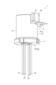
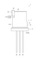
- FIG. 1 is a perspective view of an optical module according to the first embodiment.
- FIG. 2 is a perspective view of the optical module shown in FIG. 1 as viewed from below.
- 3 is an exploded perspective view of the optical module shown in FIG. 1.
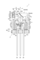
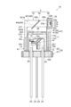
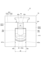
- FIG. 4 is a cross-sectional view of the optical module shown in FIG. 1 along line IV-IV.
- 5 is a front view of the optical module shown in FIG. 1.
- FIG. 6 is a rear view of the optical module shown in FIG. 1.
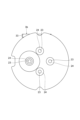
- FIG. 7 is a top view of the optical module shown in FIG. 1.
- FIG. 8 is a bottom view of the optical module shown in FIG. 1.
- FIG. 9 is a right side view of the optical module shown in FIG. 1.
- FIG. 10 is a left side view of the optical module shown in FIG. 1.
- FIG. 10 is a left side view of the optical module shown in FIG. 1.
- FIG. 11 is a bottom view of a monitor unit included in the optical module shown in FIG. 1.
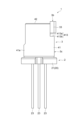
- FIG. FIG. 12 is a perspective view showing an optical module according to the second embodiment.
- 13 is an exploded perspective view of the optical module shown in FIG. 12.
- FIG. 14 is a cross-sectional view of the optical module shown in FIG. 12 taken along line XIV-XIV.
- FIG. 15 is a perspective view showing an optical module according to the third embodiment. 16 is an exploded perspective view of the optical module shown in FIG. 15.
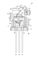
- FIG. 17 is a cross-sectional view of the optical module shown in FIG. 15 along line XVII-XVII.
- FIG. 20 is an exploded perspective view of the optical module shown in FIG. 18.
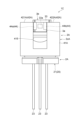
- FIG. 21 is a cross-sectional view of the optical module shown in FIG. 18 taken along line XXI-XXI.
- 22 is a front view of the optical module shown in FIG. 18.
- FIG. 23 is a rear view of the optical module shown in FIG. 18.
- FIG. 24 is a top view of the optical module shown in FIG. 18.
- FIG. 25 is a bottom view of the optical module shown in FIG. 18.
- FIG. 26 is a right side view of the optical module shown in FIG. 18.
- FIG. 27 is a left side view of the optical module shown in FIG. 18.
- FIG. 21 is a cross-sectional view of the optical module shown in FIG. 18 taken along line XXI-XXI.
- 22 is a front view of the optical module shown in
- One object of the present disclosure is to provide a monitor unit that can easily monitor laser light output from a housing that accommodates a semiconductor laser element, and an optical module that includes the monitor unit.
- a monitor unit includes a holder, an optical splitter that splits a laser beam into a first laser beam and a second laser beam, and a photodetector that detects the second laser beam.
- the light branching section and the light detection section are fixed to the holder so that the second laser beam is incident on the light detection section.
- the light branching section and the light detecting section are fixed to the holder in advance while being positioned as described above. Therefore, by attaching a monitor unit to the light source described below, the laser beam can be easily monitored.
- the holder may have a first open end, a second open end, a hollow side wall, and an end wall provided at the first open end.
- a base portion may be formed on the end wall portion to hold the light branching portion in an inclined state with respect to the output direction of the laser beam.
- the photodetector may be attached to the outer surface of the sidewall on the optical path of the second laser beam.
- An optical path may be formed in the side wall portion for passing the second laser beam to the photodetector side.
- the window side of the housing of the light source section can be accommodated inside the side wall section. Since the end wall portion is formed with a base portion that holds the light branching portion, the laser beam output from the window portion is split into the first laser beam and the second laser beam by the light branching portion held by the base portion. can. Since the side wall has an optical path through which the second laser beam passes to the photodetector side, the second laser beam can be detected by the photodetector attached to the side surface of the side wall.
- a notch portion having a first surface perpendicular to the optical path of the second laser beam may be provided on the outer surface of the side wall portion, and the light detection portion may be fixed to the first surface.
- the photodetector By attaching the photodetector to the notch, the photodetector can be easily attached and productivity is improved.
- the side wall portion may have a rectangular outer shape when viewed from the output direction of the laser light.
- the end wall portion has a first end wall portion and a second end wall portion, and the first end wall portion and the second end wall portion are separated from each other across the optical path of the second laser beam. good too.
- the first end wall portion has a first inclined surface that is inclined with respect to the output direction of the laser beam
- the second end wall portion has a second inclined surface that is inclined with respect to the output direction of the laser beam.
- the first inclined surface and the second inclined surface may constitute the base portion.
- the laser beam and the second laser beam can pass therebetween. Since the first slanted surface and the second slanted surface are formed on the first end wall portion and the second end wall portion, it is possible to secure an arrangement area for the light branching portion. By fixing the light branching part to the first inclined surface and the second inclined surface, the light branching part can be arranged in a state of being inclined with respect to the output direction of the laser light.
- the end wall portion may have a first region facing each other across the optical path of the second laser beam, and a second region facing each other across the light branching portion.
- a distance between the second regions may be longer than a distance between the first regions.
- the first inclined surface and the second inclined surface may be surfaces connecting the first region and the second region.
- the photodetector may detect laser light in the visible region.
- the monitor unit is required to monitor visible laser light from the light source. Therefore, the configuration of the monitor unit described above is effective.
- An optical module may include the monitor unit and a light source section to which the monitor unit is attached.
- the light source section may include a semiconductor laser element that outputs the laser light, and a housing that houses the semiconductor laser element and has a window that transmits the laser light.
- the second open end may be fixed to a main surface of a support plate of the housing, and the side wall may accommodate the window inside.
- the optical module includes the monitor unit, it is possible to easily monitor the laser light output from the housing.
- a lens may be provided in the window. This configuration facilitates miniaturization of the light source unit, and as a result, facilitates miniaturization of the optical module.
- a window member having no lens function may be provided in the window portion. This configuration can be applied to an optical system using a divergent beam.
- the housing may have a lens component so as to cover the window, and the window may be provided with a window member having no lens function. With this configuration, any lens component can be attached, and a desired optical system can be realized.
- An optical module further includes a plurality of the semiconductor laser elements, and a combining section for combining the plurality of laser beams output from the plurality of the semiconductor laser elements, wherein the plurality of the semiconductor laser elements and the multiplexing unit may be accommodated in the package.
- a combining section for combining the plurality of laser beams output from the plurality of the semiconductor laser elements, wherein the plurality of the semiconductor laser elements and the multiplexing unit may be accommodated in the package.
- the plurality of laser beams may include red laser beams, blue laser beams, and green laser beams.
- the light module functions as a trichromatic light source.
- the optical module may have an optical fiber and a ferrule. With this configuration, the laser light can be optically coupled to the optical fiber, and the overall size of the optical module can be reduced.
- FIG. 1 is a perspective view of an optical module according to the first embodiment.
- FIG. 2 is a perspective view of the optical module shown in FIG. 1 as viewed from below in FIG. 3 is an exploded perspective view of the optical module shown in FIG. 1.
- FIG. FIG. 4 is a cross-sectional view of the optical module shown in FIG. 1 along line IV-IV. 5 is a front view of the optical module shown in FIG. 1.
- FIG. 6 is a rear view of the optical module shown in FIG. 1.
- FIG. 7 is a top view of the optical module shown in FIG. 1.
- FIG. 8 is a bottom view of the optical module shown in FIG. 1.
- FIG. FIG. 9 is a right side view of the optical module shown in FIG. 1, and shows the optical module when viewed from the right side in FIG.
- FIG. 10 is a left side view of the optical module shown in FIG. 1, and shows the optical module when viewed from the left side in FIG.
- FIG. 11 is a diagram of the monitor unit included in the optical module shown
- the optical module 1A has a light source section 2 for outputting laser light L and a monitor unit 3 for detecting part of the laser light L output from the light source section 2 .
- the light source unit 2 outputs laser light L.
- the light source unit 2 is a light source module capable of outputting laser light L in the visible range.
- the light source unit 2 is a light source module capable of outputting laser light L including at least one of red laser light Lr, green laser light Lg, and blue laser light Lb.
- the light source unit 2 is, for example, a CAN-type light source module.
- the light source section 2 includes a first LD (first semiconductor laser element) 10a, a second LD (second semiconductor laser element) 10b, a third LD (third semiconductor laser element) 10c, a combining section 11, and a housing 20. and
- the first LD 10a is a semiconductor laser element that outputs red laser light Lr.
- An example of the oscillation wavelength (or center wavelength) of the red laser light Lr is 620 nm or more and 650 nm or less.
- the second LD 10b is a semiconductor laser element that outputs green laser light Lg.
- An example of the oscillation wavelength (or center wavelength) of the green laser light Lg is 510 nm or more and 540 nm or less.
- the third LD 10c is a semiconductor laser element that outputs blue laser light Lb.
- An example of the oscillation wavelength (or center wavelength) of the blue laser light Lb is 435 nm or more and 465 nm or less.
- Examples of the first LD 10a, second LD 10b and third LD 10c are laser diode chips (LD chips).
- the first LD 10a, the second LD 10b and the third LD 10c are mounted on the support plate 12.
- the first LD 10a, the second LD 10b, and the third LD 10c may be mounted on the support plate 12 via a base portion 13 (for example, a submount).
- Examples of materials for the support plate 12 are metals and ceramics.
- a material having a thermal expansion coefficient close to that of the semiconductor material forming the first LD 10a, the second LD 10b, and the third LD 10c can be used.
- AlN, SiC, Si, or diamond can be used.
- the second LD 10b and the third LD 10c are arranged laterally with respect to the optical axis of the first LD 10a.
- the second LD 10b and the third LD 10c are arranged on the same side with respect to the optical axis of the first LD 10a.
- the second LD 10b and the third LD 10c are arranged on the same side with respect to the output direction of the red laser light Lr from the first LD 10a, and the green laser light Lg and the blue laser light Lb from the second LD 10b and the third LD 10c. , intersects the output direction of the red laser light Lr (substantially orthogonal in FIG. 4).
- the optical axis of the first LD 10a coincides with the optical axis A of the light source section 2 (see FIG. 3). That is, the output direction of the laser light L from the light source unit 2 matches the output direction of the red laser light Lr.
- the multiplexing unit 11 is configured to be able to multiplex the red laser light Lr, the green laser light Lg, and the blue laser light Lb. An example of the multiplexing unit 11 will be described based on the multiplexing unit 11 shown in FIG.
- the combining unit 11 has a filter 11a and a filter 11b.
- the filters 11a and 11b are, for example, wavelength selective filters.
- filters 11a and 11b have multilayer filters (eg, dielectric multilayer filters) formed on transparent substrates.
- An example of a transparent substrate is a glass plate.
- the transparent substrate may also be part of filters 11a and 11b.
- the filter 11a transmits the red laser light Lr and reflects the green laser light Lg from the second LD 10b toward the filter 11b. Thereby, the red laser beam Lr and the green laser beam Lg are combined.
- Filter 11b transmits combined light of red laser light Lr and green laser light Lg (that is, red laser light Lr and green laser light Lg), and reflects blue laser light Lb from third LD 10c to the opposite side of filter 11a. .
- the laser light L is obtained as a combined light in which the red laser light Lr, the green laser light Lg and the blue laser light Lb are combined.
- the red laser light Lr, the green laser light Lg, and the blue laser light Lb are all output. However, if any one of the red laser beam Lr, the green laser beam Lg, and the blue laser beam Lb is not output, the laser beam L is light obtained by combining the laser beams of the colors being output.
- the filters 11a and 11b are mounted on the support plate 12 while being arranged so as to generate combined light of the red laser light Lr, the green laser light Lg and the blue laser light Lb. At least one of the filter 11 a and the filter 11 b may be mounted on the support plate 12 via the base portion 14 .
- the housing 20 accommodates the first LD 10a, the second LD 10b and the third LD 10c. As shown in FIGS. 3 and 4, housing 20 has support plate 21 and cover 22 . In this embodiment, the housing 20 is a CAN type housing.
- the support plate 21 is a member to which the support plate 12 on which the first LD 10a, the second LD 10b, the third LD 10c and the wave combining section 11 are mounted is fixed.
- the support plate 12 is fixed to the support plate 21 so that the main surface 12a of the support plate 12 and the main surface 21a of the support plate 21 are perpendicular to each other.
- the laser light L is output in the normal direction of the main surface 21 a of the support plate 21 .
- Support plate 21 is, for example, a disk-shaped member.
- An example of the support plate 21 is a stem. Examples of materials for the support plate 21 are metal and ceramic.
- a plurality of conductive members 23 are passed through the support plate 21 in the thickness direction.
- four conductive members 23 are passed through the support plate 21 .
- Each conductive member 23 is a bar-shaped member extending in one direction, and is, for example, a lead pin.
- Each conductive member 23 protrudes toward the main surface 21 a of the support plate 21 .
- the plurality of conductive members 23 are used for power supply to the first LD 10a, second LD 10b and third LD 10c, GND lines, and the like.
- An insulating member 24 is arranged around a portion of each conductive member 23 located inside the support plate 21 to prevent a short circuit between the conductive member 23 and the support plate 21 .
- the cover 22 includes a hollow side wall portion 221 with both ends open, and an end wall portion 222 closing one of the open ends.
- a flange portion may be formed at the end portion of the side wall portion 221 on the side of the support plate 21 .
- the cover 22 may be a cap (CAN cap) on the CAN-type housing 20 .
- the open ends that are not blocked by the end walls 222 are fixed to the support plate 21 .
- the cover 22 and the support plate 21 form an accommodation space that accommodates, for example, the first LD 10a, the second LD 10b, and the third LD 10c.
- the end wall portion 222 is hermetically sealed to the support plate 21, for example.
- the end wall portion 222 is formed with an opening (window portion) 222a through which the laser beam L passes.
- the laser light L is output to the outside of the housing 20 through the opening 222a.
- the lens 25 is fitted in the opening 222a.
- the lens 25 is a lens that converts the laser light L into convergent light, and is, for example, a ball lens.
- the monitor unit 3 is a unit for detecting part of the laser light L output from the opening 222a.
- the monitor unit 3 has a light branching portion 3a, a light detecting portion 3b, and a holder 3c.
- the light branching portion 3a is arranged to be inclined with respect to the output direction of the laser light L from the opening 222a (the direction of the optical axis A of the light source portion 2). In this embodiment, unless otherwise specified, the angle of inclination of the light branching portion 3a with respect to the output direction of the laser light L is 45 degrees.
- the light splitter 3a splits the laser beam L into a first laser beam L1 and a second laser beam L2.
- the first laser beam L1 is a portion of the laser beam L that travels along the output direction of the laser beam L, and is output light from the optical module 1.
- the second laser beam L2 is a portion of the laser beam L that travels in a direction different from the output direction of the laser beam L.
- the second laser beam L2 is light obtained by partially reflecting the laser beam L at the light branching portion 3a.
- the second laser light L2 is light (monitor light) for checking whether or not the red laser light Lr, the green laser light Lg, and the blue laser light Lb are output from the first LD 10a, the second LD 10b, and the third LD 10c in a desired output state. light).
- the first laser beam L1 is output light from the optical module 1, and the second laser beam L2 is light for inspection. Therefore, the amount of light of the first laser beam L1 is greater than that of the second laser beam L2.
- An example of the reflectance of the laser light L at the light branching portion 3a is 5% to 15%.
- An example of the light branching portion 3a is a glass plate.
- the second laser beam L2 is obtained by Fresnel reflection on the surface of the glass plate.
- the photodetector 3b is arranged on the optical path of the second laser beam L2.
- the photodetector 3b includes at least one of a first photodetector 31a, a second photodetector 31b, and a third photodetector 31c arranged in parallel. Examples of the first photodetector 31a, the second photodetector 31b and the third photodetector 31c are photodiodes.
- a first filter 32a, a second filter 32b and a third filter 32c are arranged on the incident surface side of the second laser beam L2 in the first photodetector 31a, the second photodetector 31b and the third photodetector 31c. ing.
- the first filter 32a, the second filter 32b, and the third filter 32c are filters that selectively pass the red laser light Lr, the green laser light Lg, and the blue laser light Lb.
- the first photodetector 31a detects the red laser beam Lr of the second laser beam L2
- the second photodetector 31b detects the green laser beam Lg of the second laser beam L2.
- the third photodetector 31c detects the blue laser light Lb of the second laser light L2.
- the first photodetector 31a, the second photodetector 31b, and the third photodetector 31c are electrically connected to a control device (not shown).
- the controller converts the laser light L into red laser light Lr, green laser light Lg and blue laser light Lb according to the detection results of the first photodetector 31a, the second photodetector 31b and the third photodetector 31c. controls the first LD 10a, the second LD 10b, and the third LD 10c so that is in a desired state (desired amount of light, etc.).
- the photodetector 3b has a housing 33 that accommodates the first photodetector 31a, the second photodetector 31b, and the third photodetector 31c.
- a window portion 33a for passing the second laser beam L2 is formed in the wall of the housing 33 on the incident side of the second laser beam L2.
- the window portion 33 a can be configured by fitting a transparent window member (for example, a glass plate) or the like into an opening formed in the housing 33 .
- An example of the shape of the window portion 33a is rectangular as shown in FIG.
- the shape of the window portion 33a may be square or circular.
- the number of photodetectors included in the photodetector 3b may be one.
- the incident surface of the second laser beam L2 in the photodetector is virtually divided into a first area, a second area and a third area, and the red laser beam L2 is detected in the first area, the second area and the third area.
- Light Lr, green laser light Lg and blue laser light Lb are detected.
- a first filter 32a, a second filter 32b and a third filter 32c are arranged for the first area, the second area and the third area.
- the holder 3c is a member to which the light branching part 3a and the light detection part 3b are fixed, and is attached to the housing 20.
- the holder 3 c functions as an adapter for arranging the light branching section 3 a and the light detecting section 3 b with respect to the light source section 2 .
- the holder 3 c has a hollow side wall portion 41 (hollow body) and an end wall portion 42 .
- the side wall portion 41 is a hollow member (hollow body) capable of accommodating the portion of the housing 20 on the side of the opening 222a.
- the side wall portion 41 accommodates the window portion 33a inside.
- the side wall portion 41 is cylindrical.
- An example of the material of the side wall portion 41 is metal (for example, stainless steel (SUS)).
- An example of sidewall 41 is a cylindrical metal sleeve.
- the side wall portion 41 has a first open end portion 411 and a second open end portion 412 .
- the second open end 412 is the end opposite to the first open end 411 .
- the side wall portion 41 is fixed to the housing 20 by joining the second open end portion 412 to the main surface 21 a of the support plate 21 of the housing 20 .
- the side wall portion 41 can be fixed to the support plate 21 by, for example, resistance welding or laser welding.
- the side wall portion 41 may be bonded to the support plate 21 with an adhesive, or may be bonded to the support plate 21 using solder.
- a step portion (or notch portion) 413 recessed toward the central axis side of the side wall portion 41 is formed on the first open end portion 411 side of the outer surface 41 a of the side wall portion 41 .
- the stepped portion 413 functions as a portion (photodetector mounting portion) on which the photodetector 3b is mounted.
- the stepped portion 413 has a first surface 413a that intersects the optical path of the second laser beam L2, and a second surface 413b that intersects the first surface 413a.
- the first surface 413a is orthogonal to the optical path of the second laser beam L2
- the second surface 413b is orthogonal to the first surface 413a.
- the first surface 413a is a surface to which the photodetector 3b is fixed, and in one embodiment, the first surface 413a is a flat surface.
- a recess 414 recessed from the first open end 411 toward the second open end 412 is formed in a portion of the side wall portion 41 (specifically, the portion where the stepped portion 413 is formed). .
- the recess 414 functions as an optical path for passing the second laser beam L2.
- a recessed portion 415 recessed from the first open end portion 411 toward the second open end portion 412 may be formed in the side wall portion 41 in a region facing the recessed portion 414 .
- the form in which the concave portion 415 is formed will be described.
- the end wall portion 42 is provided at the first open end portion 411 .
- a base portion 44 is formed on the end wall portion 42 to hold the light branching portion 3a in an inclined state with respect to the output direction of the laser light L from the opening 222a.
- An example of the end wall portion 42 will be specifically described.
- the end wall portion 42 has a first end wall portion 421 and a second end wall portion 422 . As shown in FIG. 7, the first end wall portion 421 and the second end wall portion 422 are spaced apart so as to sandwich the optical path (or recess 414) of the second laser beam L2. In FIG. 7, the second laser beam L2 is indicated by a dashed line to indicate the optical path of the second laser beam L2.
- the first end wall portion 421 has a first stepped portion 421a toward the second end wall portion 422 for securing an arrangement area for the light branching portion 3a.
- the first stepped portion 421 a is a portion of the first end wall portion 421 that is recessed away from the second end wall portion 422 .
- the first end wall portion 421 has a first step surface (first inclined surface) 44a that is inclined with respect to the output direction of the laser light L. As shown in FIG.
- the second end wall portion 422 has a second stepped portion 422a toward the first end wall portion 421 for securing an arrangement area for the light branching portion 3a.
- the second stepped portion 422 a is a recessed portion away from the first end wall portion 421 .
- the second end wall portion 422 has a second stepped surface (second inclined surface) 44b that is inclined with respect to the output direction of the laser light L. As shown in FIG.
- the inclination angle of the second step surface 44b with respect to the output direction of the laser beam L is the same as the inclination angle of the first step surface 44a with respect to the output direction of the laser beam L.
- the surfaces facing each other of the first end wall portion 421 and the second end wall portion 422 have the first region 42a and the second region 42b.
- the first regions 42a face each other across the optical path of the second laser beam L2.
- the second regions 42b face each other with the light branching portion 3a interposed therebetween.
- the first region 42a is closer to the photodetector 3b than the second region 42b.
- the distance d2 between the second regions 42b of the first end wall 421 and the second end wall 422 is equal to the distance d2 between the first regions 42a of the first end wall 421 and the second end wall 422. longer than the distance d1 between The distance d2 is a length that allows the optical branching portion 3a to be arranged between the second regions 42b of the first end wall portion 421 and the second end wall portion 422.
- FIG. 7 shows that allows the optical branching portion 3a to be arranged between the second regions 42b of the first end wall portion 421 and the second end wall portion 422.
- a surface connecting the first region 42a and the second region 42b in the first end wall portion 421 is inclined with respect to the output direction of the laser light L and corresponds to the first stepped surface 44a.
- a surface connecting the first region 42a and the second region 42b in the second end wall portion 422 is inclined with respect to the output direction of the laser light L and corresponds to the second stepped surface 44b.
- the optical splitter 3a is fixed to the first step surface 44a and the second step surface 44b. That is, the first stepped surface 44 a and the second stepped surface 44 b function as the base portion 44 . Therefore, the optical branching portion 3a is formed so as to be positioned on the optical path of the laser beam L. As shown in FIG. When the light branching portion 3a has a plate shape such as a glass plate, the inclination angles of the first step surface 44a and the second step surface 44b substantially match the inclination angle of the light branching portion 3a with respect to the output direction of the laser light L. do.
- the light branching portion 3a can be fixed to the first step surface 44a and the second step surface 44b using an adhesive or solder.
- the light branching portion 3a and the light detecting portion 3b are fixed to the holder 3c.
- the photodetector 3b detects the second laser beam L2 from the optical branch 3a. Therefore, the stepped portion 413 for fixing the light detection portion 3b and the base portion 44 (specifically, the first stepped surface 44a and the second stepped surface 44b) to which the light branching portion 3a is fixed are the second laser beams.
- the light branching portion 3a and the light detecting portion 3b are formed so as to be held in alignment with each other by the holder 3c so that L2 is incident on the light detecting portion 3b.
- the holder 3c can be manufactured as follows. First, a first member having a side wall portion 41 and an end wall portion that completely closes the first open end portion 411 of the side wall portion 41 is manufactured.
- the first member can be manufactured by, for example, an NC lathe. After that, by processing the first member, for example, the stepped portion 413 for arranging the light detection portion 3b, the first stepped portion 421a and the second stepped portion 422a (the base portion 44) for arranging the light branching portion 3a. including ).
- the holder 3c is thus obtained.
- the light branching portion 3a is fixed to the base portion 44 (specifically, the first step surface 44a and the second step surface 44b), and the light detection portion 3b is fixed to the step portion 413. .
- the monitor unit 3 is obtained.
- the window portion 33 a and the cover 22 can be accommodated inside the side wall portion 221 . Since the light branching portion 3a is held on the base portion 44 formed on the end wall portion 42, the laser light L is incident on the light branching portion 3a by accommodating the window portion 33a and the cover 22 inside the side wall portion 41. do. Therefore, the laser light L can be split into the first laser light L1 and the second laser light L2 at the light splitter 3a.
- the side wall portion 41 is formed with the concave portion 414 for passing the second laser beam L2, even if the photodetector portion 3b is fixed to the outer surface 41a of the side wall portion 41, the photodetector portion 3b can be detected by the second laser beam L2. Laser light L2 can be detected.
- the light branching portion 3a and the light detecting portion 3b are aligned with respect to the side wall portion 41 and fixed. Therefore, by covering the cover 22 with the side wall portion 41 and fixing it to the support plate 21, the positions of the light branching portion 3a and the light detecting portion 3b with respect to the light source portion 2 are automatically determined. Therefore, when the laser light L output from the light source unit 2 is monitored outside the light source unit 2, the light detection unit 3b can be easily arranged. can be monitored.
- the inclination angle of the light branching portion 3a is fixed, and the light branching portion 3a has a sufficient size to branch the laser light L. Therefore, the laser beam L can be split into the first laser beam L1 and the second laser beam L2 even if the laser beam L does not necessarily pass through the center of the optical splitter 3a, and the second laser beam L2 can be detected by the photodetector 3b. It is possible.
- the first end wall portion 421 and the second end wall portion 422 are separated from each other across the optical path of the second laser beam L2.
- the laser light L and the second laser light L2 can pass between the second end wall portions 422 . Since the first end wall portion 421 and the second end wall portion 422 are formed with the first stepped portion 421a and the second stepped portion 422a, the arrangement area for the light branching portion 3a can be secured. Since the first stepped surface 44a and the second stepped surface 44b are inclined surfaces, the light branching portion 3a is arranged in a state inclined with respect to the output direction of the laser light L by fixing the light branching portion 3a to them. It is possible.
- the area from the arrangement position of the light branching portion 3a to the recess 415 in the monitor unit 3 is open as shown in FIG. Therefore, it is easy to fix the optical branching portion 3 a to the base portion 44 .
- the light source section 2 does not have a light detection section for monitoring the light output states of the first LD 10a, the second LD 10b and the third LD 10c. Even with such a light source unit 2, by covering the cover 22 with the monitor unit 3 and fixing it to the support plate 21, the light detection unit 3b can be easily aligned with the light source unit 2 as described above, and then the laser beam can be detected. Part of the light L (second laser light L2) can be detected. As a result, the first LD 10a, the second LD 10b and the third LD 10c can be controlled to desired output states.
- the optical module 1 there is no need to dispose a photodetector for monitoring the optical output states of the first LD 10a, the second LD 10b, and the third LD 10c inside the housing 20. Therefore, the light source section 2 can be miniaturized, and as a result, the optical module 1 can be miniaturized.
- the configuration of the optical module 1 and the monitor unit 3 is effective when the optical module 1 is mounted on a wearable device such as smart glasses.
- the lens 25 is attached to the cover 22 in the optical module 1 described in this embodiment. Therefore, for example, it is not necessary to arrange a lens or the like for condensing laser light or collimating the laser light in the housing space of the first LD 10a, the second LD 10b, and the third LD 10c inside the cover 22. FIG. In this respect as well, the size of the light source unit 2 can be reduced.
- the design of the light source unit 2 is easy, and when the photodetector is provided Necessary optical axis adjustment is also unnecessary. Therefore, the light source section 2 can be easily manufactured, and as a result, the optical module 1 can be easily manufactured.
- the optical module 1 monitors, for example, a CAN light source module (light source unit 2 in this embodiment) that does not have a photodetector for monitoring the light output states of the first LD 10a, the second LD 10b, and the third LD 10c as described above. It can be manufactured easily by attaching the unit 3 . Therefore, it is easy to manufacture the optical module 1 .
- a CAN light source module light source unit 2 in this embodiment
- a laser diode that outputs laser light in the visible region
- the light output of the laser light output forward and backward is not in a proportional relationship. Therefore, when monitoring the laser light in the visible region output from the LD, it is necessary to divide the laser light output forward by the light splitter and detect it with the photodetector. Therefore, if a photodetector for monitoring the output state of the red laser light Lr, the green laser light Lg, and the blue laser light Lb output from the first LD 10a, the second LD 10b, and the third LD 10c is arranged in the light source unit 2, light detection In addition to the device, the light branching section is also arranged within the light source section 2 .
- the photodetector 30 for monitoring can be arranged outside the light source 2, so that the light source 2 can be miniaturized.
- the optical module 1 and the monitor unit 3 are effective when the light source section 2 includes an LD that outputs laser light in the visible region.
- the light source unit 2 does not have a photodetector, while the monitor unit 3 has a photodetector 3b. Therefore, it is not necessary to pass the conductive member 23 for light detection through the support plate 21 of the housing 20 . That is, the number of conductive members 23 passed through the support plate 21 can be reduced. Since the monitor unit 3 includes the photodetector 3b, it is easy to use, for example, a flexible printed circuit board (FPC). Since the monitor unit 3 includes the photodetector 3b, it is easy to replace the photodetector 3b.
- FPC flexible printed circuit board
- the laser light L can include the red laser light Lr, the green laser light Lg, and the blue laser light Lb. Therefore, the optical module 1 including the light source section 2 can be used as a three-color light source module.
- FIG. 12 is a perspective view showing another embodiment of the optical module.
- 13 is an exploded perspective view of the optical module shown in FIG. 12.
- FIG. 14 is a cross-sectional view of the optical module shown in FIG. 12 taken along line XIV-XIV.
- the optical module 1A shown in FIGS. 12 to 14 has a light source section 2A and a monitor unit 3.
- the light source section 2A differs from the light source section 2 mainly in that the aperture 222a does not have a lens and that the window member 26 having no lens function is attached to the aperture 222a. Since the configuration of the optical module 1A is the same as that of the optical module 1 other than these points of difference, the above points of difference will be explained, and the explanation of other configurations will be omitted.
- the window member 26 is fixed to the inner surface of the end wall portion 222 so as to close the opening 222a of the end wall portion 222 of the cover 22 from the inside.
- An example of the window member 26 is a glass plate.
- the window member 26 may be fitted in the opening 222a.
- the window member 26 may be fixed to the outer surface of the end wall portion 222 so as to block the opening 222a of the cover 22 from the outside. In a configuration having a window member 26, the window member 26 can be part of the window as well as the opening 222a.
- the configuration of the optical module 1A is the same as that of the optical module 1 except that it has a light source unit 2A instead of the light source unit 2. Further, the light source section 2A has the same configuration as the light source section 2 except that it does not have the lens 25 and the window member 26 is attached to the opening 222a. Therefore, the optical module 1A has effects similar to those of the optical module 1.
- FIG. 1 The configuration of the optical module 1A is the same as that of the optical module 1 except that it has a light source unit 2A instead of the light source unit 2. Further, the light source section 2A has the same configuration as the light source section 2 except that it does not have the lens 25 and the window member 26 is attached to the opening 222a. Therefore, the optical module 1A has effects similar to those of the optical module 1. FIG.
- FIG. 15 is a perspective view showing an optical module according to the third embodiment.
- 16 is an exploded perspective view of the optical module shown in FIG. 15.
- FIG. 17 is a cross-sectional view of the optical module shown in FIG. 15 along line XVII-XVII.
- the optical module 1B shown in FIGS. 15 to 17 has a light source section 2B and a monitor unit 3.
- the light source section 2 is mainly similar to the light source section 2 in that the window member 26 having no lens function is attached to the opening 222a and the lens component is attached to the outer surface of the end wall section 222 in place of the lens 25. differ. Since the configuration of the optical module 1B other than these differences is the same as that of the optical module 1, the above differences will be explained and the explanation of other configurations will be omitted.
- the window member 26 covers the inner surface of the end wall portion 222 so as to close the opening 222a of the cover 22 from the inside. is fixed to An example of the window member 26 is a glass plate.
- the window member 26 may be fitted in the opening 222a.
- the lens component 27 has a lens 27a.
- the lens component 27 may have a holder 27b that holds the lens 27a.
- the lens 27a is fixed to the outer surface of the end wall portion 222 while being fitted in the holder 27b.
- Lens 27 a is provided to cover window member 26 .
- the holder 27b may be fixed to the end wall portion 222 via a plate-like base portion 28. As shown in FIG. In this case, the base portion 28 is formed with an opening corresponding to the opening 222a.
- An example of the lens 27a is a collimating lens that collimates the first laser beam L1.
- the lens component 27 may have, for example, a plurality of lenses, and the plurality of lenses may realize a collimating function.
- the lens component 27 may have a function of converting the first laser beam L1 into light other than collimated light (for example, convergent light).
- the configuration of the optical module 1B is the same as that of the optical module 1 except that it has a light source unit 2B instead of the light source unit 2. Furthermore, the light source section 2B has the same features as the light source except that the window member 26 having no lens function is attached to the opening 222a and the lens component 27 is attached to the outer surface of the end wall section 222 instead of the lens 25.
- the configuration is the same as that of Part 2. Therefore, the optical module 1B has effects similar to those of the optical module 1A.
- the collimated laser beam L is output from the light source unit 2B. Therefore, the first laser beam L1 as collimated light can also be output from the optical module 1B.
- FIG. 18 is a perspective view showing the optical module according to the fourth embodiment.
- 19 is a perspective view of the optical module shown in FIG. 18 as viewed from below in FIG. 18.
- FIG. 20 is an exploded perspective view of the optical module shown in FIG. 18.
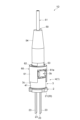
- FIG. 21 is a cross-sectional view of the optical module shown in FIG. 18 taken along line XXI-XXI.
- 22 is a front view of the optical module shown in FIG. 18.
- FIG. 23 is a rear view of the optical module shown in FIG. 18.
- FIG. 24 is a top view of the optical module shown in FIG. 18.
- FIG. 25 is a bottom view of the optical module shown in FIG. 18.
- FIG. 26 is a right side view of the optical module shown in FIG. 18.
- FIG. 27 is a left side view of the optical module shown in FIG. 18.
- FIG. 18 is a perspective view showing the optical module according to the fourth embodiment.
- 19 is a perspective view of the optical module shown in FIG. 18 as viewed from below
- the optical module 1C shown in FIGS. 18 to 27 has a light source section 2A and a monitor unit 3A.
- the light source unit 2A included in the optical module 1C is the same as the light source unit 2A described in the second embodiment, so description thereof will be omitted.
- the monitor unit 3A has a light branching section 3a, a light detection section 3b and a holder 3cA. Since the configurations of the light branching section 3a and the light detecting section 3b are the same as those of the monitor unit 3 described in the first embodiment, description thereof will be omitted.
- the holder 3cA mainly differs from the holder 3c described in the first embodiment in that it has a side wall portion 41A instead of the side wall portion 41.
- the side wall portion 41A in the fourth embodiment has a square shape (for example, a square or a rectangle) when viewed from the output direction of the laser light L. , and is different from the side wall portion 41 .
- An example of the side wall portion 41A is a rectangular sleeve having a rectangular outer shape.
- the side wall portion 41A has a first open end portion 411 and a second open end portion 412 similarly to the side wall portion 41, and is hollow so as to accommodate the opening 222a side of the housing 20 (the portion of the cover 22).
- the inner surface shape of the side wall portion 41A when viewed from the output direction of the laser beam L is circular corresponding to the shape of the cover 22, but may be square if the cover 22 portion can be accommodated.
- the side wall portion 41A has a second open end portion 412 fixed to the support plate 21 in the same manner as in the first embodiment.
- the side wall portion 41A is formed with a stepped portion 413 for attaching the photodetecting portion 3b and a concave portion 414 for passing the second laser beam L2. Since the outer shape of the side wall portion 41A is rectangular as described above, the stepped portion 413 can also be a notch portion formed by notching a corner formed by one side surface 41b of the side wall portion 41A and the end wall portion 42A. be.
- a recess 415 may be formed in the side wall portion 41A on the opposite side of the recess 414 as in the case of the side wall portion 41A. The formation of the recessed portion 415 makes it easy to attach the light branching portion 3a to the side wall portion 41A.
- An end wall portion 42A is provided at the first open end portion 411 of the side wall portion 41A.
- the end wall portion 42A has the same configuration as the end wall portion 42 except that the shape of the boundary portion between the end wall portion 42A and the side wall portion 41A differs from that in the first embodiment according to the shape of the side wall portion 41A. . Therefore, the end wall portion 42A is formed with a base portion 44 for holding the light branching portion 3a.
- the end wall portion 42A may have a first end wall portion 421A and a second end wall portion 422A.
- the arrangement state of the first end wall portion 421A and the second end wall portion 422A is the same as the case of the first end wall portion 421 and the second end wall portion 422 in the first embodiment.
- the configuration of the first end wall portion 421A and the second end wall portion 422A depends on the shape of the side wall portion 41A, the shape of the boundary portion between the side wall portion 41A and the first end wall portion 421A, and the shape of the boundary portion between the side wall portion 41A and the second end wall portion.
- first end wall portion 421 and the second end wall portion 422 The same as the first end wall portion 421 and the second end wall portion 422 except that the shape of the boundary portion with the portion 422A is different from that of the first end wall portion 421 and the second end wall portion 422 in the first embodiment. is. Therefore, description of the first end wall portion 421A and the second end wall portion 422A is omitted.
- the optical module 1C is the same as the optical module 1A according to the second embodiment except that the monitor unit 3A is used instead of the monitor unit 3.
- the configuration of the monitor unit 3A is substantially the same as that of the monitor unit 3, except that the side wall 41A has a rectangular outer shape when viewed from the output direction of the laser light L. As shown in FIG. Therefore, the optical module 1C has effects similar to those of the optical module 1A (corresponding to effects similar to those of the optical module 1).
- FIG. 28 is a perspective view showing an optical module according to the fifth embodiment.
- 29 is an exploded perspective view of the optical module shown in FIG. 28.
- the optical module 1D shown in FIGS. 28 and 29 is a pigtail-type optical module having an optical output section 4, an optical transmission medium 50, and a ferrule holder 60.
- FIG. 1D is a pigtail-type optical module having an optical output section 4, an optical transmission medium 50, and a ferrule holder 60.
- the optical output unit 4 is the optical module 1 according to the first embodiment, and outputs the first laser beam L1. That is, the light output section 4 has a light source section 2 and a monitor unit 3 , and the monitor unit 3 is fixed to the light source section 2 .
- the configurations of the light source section 2 and the monitor unit 3 are the same as in the first embodiment. Therefore, description of the light source unit 2 and the monitor unit 3 is omitted.
- the optical output section 4, the ferrule holder 60, and the optical transmission medium 50 are arranged along the optical axis A of the optical output section 4 (the axis along the output direction of the first laser beam L1). ing.
- the optical transmission medium 50 receives the first laser light L1 output from the optical output section 4.
- the optical transmission medium 50 has an optical fiber 51 and a ferrule 52 .
- the ferrule 52 is a hollow rod-shaped member.
- the ferrule 52 holds the optical fiber 51 by inserting the optical fiber 51 into the ferrule 52 .
- An example of a material for ferrule 52 is metal.
- a flange portion 53 (or a skirt portion) that defines the amount of insertion of the ferrule 52 into the ferrule holder 60 may be provided on the outer periphery of the end portion 52a of the ferrule 52 on the ferrule holder 60 side.
- the flange portion 53 may be integrated with the ferrule 52 .
- a protective cover 54 may be attached to the ferrule 52 together with the ferrule 52 to protect the ferrule 52 near the insertion port for the optical fiber 51 (the end opposite to the ferrule holder 60).
- Protective cover 54 is, for example, a rubber boot and covers ferrule 52 .
- the ferrule holder 60 has a side wall portion 61 and an end wall portion 62 .
- the ferrule holder 60 is a member that attaches the ferrule 52 to the optical output section 4 (optical module 1).
- the ferrule holder 60 can also function as a member for aligning the optical axis of the optical fiber 51 and the optical axis of the optical output section 4 .
- the shape of the side wall portion 61 is hollow with both ends open.
- the side wall portion 61 covers the side wall portion 41 of the monitor unit 3 included in the light output portion 4 .
- the side wall portion 61 can accommodate the side wall portion 41 inside, and by covering the side wall portion 41 with the side wall portion 61, the optical axis of the optical fiber 51 and the optical axis of the light output portion 4 can be aligned. It is sufficient if it has a shape.
- the side wall portion 61 may also be cylindrical.
- the inner diameter of the side wall portion 61 substantially matches the outer diameter of the side wall portion 41 .
- a part of the side wall portion 61 is formed with a concave portion 61a recessed from the open end on the side of the light output portion 4 toward the opposite side in order to avoid interference with the light detection portion 3b.
- the end wall portion 62 is provided so as to block the open end portion of the side wall portion 61 on the optical transmission medium 50 side.
- the end wall portion 62 is formed with an opening 62a through which the first laser beam L1 passes and in which the end portion 52a of the ferrule 52 is fitted.
- the inner diameter of opening 62a substantially matches the outer diameter of end 52a.
- the opening 62a is formed at a position where the optical axis A of the optical output section 4 and the optical axis of the optical fiber 51 are aligned with the ferrule holder 60 covering the side wall 221 and the end portion 52a being fitted in the opening 62a. ing.
- the optical axis A of the light output section 4 can be aligned with the optical axis of the optical fiber 51 by covering the side wall portion 41 with the ferrule holder 60 after the end portion 52a of the ferrule 52 is fitted in the opening 62a. can.
- the optical module 1D includes an optical output section 4 which is the optical module 1 of the first embodiment. Therefore, the optical module 1D has effects similar to those of the optical module 1 and the monitor unit 3. FIG. 1
- the number of semiconductor laser elements included in the light source section may be one or two.
- the number of semiconductor laser elements included in the light source may be four or more.
- a semiconductor laser element is not limited to a laser diode.
Landscapes
- Physics & Mathematics (AREA)
- General Physics & Mathematics (AREA)
- Optics & Photonics (AREA)
- Condensed Matter Physics & Semiconductors (AREA)
- Electromagnetism (AREA)
- Semiconductor Lasers (AREA)
- Photo Coupler, Interrupter, Optical-To-Optical Conversion Devices (AREA)
- Optical Head (AREA)
- Optical Couplings Of Light Guides (AREA)
Priority Applications (3)
| Application Number | Priority Date | Filing Date | Title |
|---|---|---|---|
| JP2023559425A JP7758053B2 (ja) | 2021-11-10 | 2022-07-15 | モニタユニットおよび光モジュール |
| US18/708,611 US20250007243A1 (en) | 2021-11-10 | 2022-07-15 | Monitor unit and optical module |
| CN202280073687.4A CN118216007A (zh) | 2021-11-10 | 2022-07-15 | 监测单元及光模块 |
Applications Claiming Priority (2)
| Application Number | Priority Date | Filing Date | Title |
|---|---|---|---|
| JP2021-183153 | 2021-11-10 | ||
| JP2021183153 | 2021-11-10 |
Publications (1)
| Publication Number | Publication Date |
|---|---|
| WO2023084848A1 true WO2023084848A1 (ja) | 2023-05-19 |
Family
ID=86335519
Family Applications (1)
| Application Number | Title | Priority Date | Filing Date |
|---|---|---|---|
| PCT/JP2022/027836 Ceased WO2023084848A1 (ja) | 2021-11-10 | 2022-07-15 | モニタユニットおよび光モジュール |
Country Status (5)
| Country | Link |
|---|---|
| US (1) | US20250007243A1 (https=) |
| JP (1) | JP7758053B2 (https=) |
| CN (1) | CN118216007A (https=) |
| TW (1) | TW202320061A (https=) |
| WO (1) | WO2023084848A1 (https=) |
Cited By (1)
| Publication number | Priority date | Publication date | Assignee | Title |
|---|---|---|---|---|
| JP7848948B1 (ja) * | 2024-10-31 | 2026-04-21 | 住友電気工業株式会社 | 光モジュール |
Citations (4)
| Publication number | Priority date | Publication date | Assignee | Title |
|---|---|---|---|---|
| JP2007194671A (ja) * | 2007-04-23 | 2007-08-02 | Nippon Telegr & Teleph Corp <Ntt> | 波長ロッカー |
| WO2013191213A1 (ja) * | 2012-06-22 | 2013-12-27 | 古河電気工業株式会社 | 光素子モジュール |
| CN104934854A (zh) * | 2015-07-07 | 2015-09-23 | 丹东依镭社电子科技有限公司 | 一种绿激光集成封装管 |
| JP2017183690A (ja) * | 2016-03-28 | 2017-10-05 | 株式会社リコー | 波長推定装置、光源装置、画像表示装置、物体装置、波長推定方法及び光源制御方法 |
-
2022
- 2022-07-15 WO PCT/JP2022/027836 patent/WO2023084848A1/ja not_active Ceased
- 2022-07-15 JP JP2023559425A patent/JP7758053B2/ja active Active
- 2022-07-15 US US18/708,611 patent/US20250007243A1/en active Pending
- 2022-07-15 CN CN202280073687.4A patent/CN118216007A/zh active Pending
- 2022-08-23 TW TW111131657A patent/TW202320061A/zh unknown
Patent Citations (4)
| Publication number | Priority date | Publication date | Assignee | Title |
|---|---|---|---|---|
| JP2007194671A (ja) * | 2007-04-23 | 2007-08-02 | Nippon Telegr & Teleph Corp <Ntt> | 波長ロッカー |
| WO2013191213A1 (ja) * | 2012-06-22 | 2013-12-27 | 古河電気工業株式会社 | 光素子モジュール |
| CN104934854A (zh) * | 2015-07-07 | 2015-09-23 | 丹东依镭社电子科技有限公司 | 一种绿激光集成封装管 |
| JP2017183690A (ja) * | 2016-03-28 | 2017-10-05 | 株式会社リコー | 波長推定装置、光源装置、画像表示装置、物体装置、波長推定方法及び光源制御方法 |
Cited By (1)
| Publication number | Priority date | Publication date | Assignee | Title |
|---|---|---|---|---|
| JP7848948B1 (ja) * | 2024-10-31 | 2026-04-21 | 住友電気工業株式会社 | 光モジュール |
Also Published As
| Publication number | Publication date |
|---|---|
| JPWO2023084848A1 (https=) | 2023-05-19 |
| US20250007243A1 (en) | 2025-01-02 |
| TW202320061A (zh) | 2023-05-16 |
| JP7758053B2 (ja) | 2025-10-22 |
| CN118216007A (zh) | 2024-06-18 |
Similar Documents
| Publication | Publication Date | Title |
|---|---|---|
| TWI290245B (en) | Optical package with an integrated lens and optical assemblies incorporating the package | |
| US6667997B2 (en) | Optical module and method of making the same | |
| CN103163605B (zh) | 接收器光学模块和装配该接收器光学模块的方法 | |
| US6572278B2 (en) | Opto-electronic device having staked connection between parts to prevent differential thermal expansion | |
| CN104136953A (zh) | 用于接收波分多路复用光学信号的接收器光学模块 | |
| TW201510574A (zh) | 光組件之製造方法及光組件 | |
| US20160349470A1 (en) | Hybrid integrated optical sub-assembly | |
| GB2421849A (en) | Optoelectronic Module and Method of Making Such a Module | |
| US8750659B2 (en) | Optical module | |
| EP3605754A1 (en) | Optical module | |
| WO2005031410A1 (ja) | 光モジュール、光送受信及び光ジョイントスリーブ | |
| US20180024303A1 (en) | Optical module | |
| JP5028503B2 (ja) | 光モジュール | |
| JP7758053B2 (ja) | モニタユニットおよび光モジュール | |
| JPWO2003060584A1 (ja) | 光導波路モジュール | |
| JP4006249B2 (ja) | 光送受信モジュール及びその実装方法、並びに光送受信装置 | |
| JP2004138749A (ja) | 光送受信モジュール及びその実装方法並びに光送受信装置 | |
| US7450862B2 (en) | Stray light insensitive detector system and amplifier | |
| US20190250342A1 (en) | Optical module and method of manufacturing optical module | |
| JPH05341143A (ja) | 表面実装型双方向伝送用モジュール | |
| JP2005134803A (ja) | 光アイソレータ付きフェルール及びそれを備えた光送受信モジュール | |
| JP2010232337A (ja) | 光源装置 | |
| JPH1164673A (ja) | 光送受信モジュール | |
| JP2004117793A (ja) | 光送受信モジュール及びその実装方法並びに光送受信装置 | |
| KR20060005078A (ko) | 통신용 양방향 광송수신 모듈 |
Legal Events
| Date | Code | Title | Description |
|---|---|---|---|
| 121 | Ep: the epo has been informed by wipo that ep was designated in this application |
Ref document number: 22892351 Country of ref document: EP Kind code of ref document: A1 |
|
| ENP | Entry into the national phase |
Ref document number: 2023559425 Country of ref document: JP Kind code of ref document: A |
|
| WWE | Wipo information: entry into national phase |
Ref document number: 202280073687.4 Country of ref document: CN |
|
| WWE | Wipo information: entry into national phase |
Ref document number: 18708611 Country of ref document: US |
|
| NENP | Non-entry into the national phase |
Ref country code: DE |
|
| 122 | Ep: pct application non-entry in european phase |
Ref document number: 22892351 Country of ref document: EP Kind code of ref document: A1 |