WO2023084848A1 - Monitoring unit and optical module - Google Patents
Monitoring unit and optical module Download PDFInfo
- Publication number
- WO2023084848A1 WO2023084848A1 PCT/JP2022/027836 JP2022027836W WO2023084848A1 WO 2023084848 A1 WO2023084848 A1 WO 2023084848A1 JP 2022027836 W JP2022027836 W JP 2022027836W WO 2023084848 A1 WO2023084848 A1 WO 2023084848A1
- Authority
- WO
- WIPO (PCT)
- Prior art keywords
- light
- wall portion
- optical module
- laser
- end wall
- Prior art date
Links
- 230000003287 optical effect Effects 0.000 title claims description 205
- 238000012544 monitoring process Methods 0.000 title abstract description 10
- 239000004065 semiconductor Substances 0.000 claims description 31
- 238000001514 detection method Methods 0.000 claims description 20
- 239000013307 optical fiber Substances 0.000 claims description 13
- 230000000694 effects Effects 0.000 description 7
- 239000011521 glass Substances 0.000 description 7
- 239000000463 material Substances 0.000 description 7
- 230000005540 biological transmission Effects 0.000 description 6
- 239000002184 metal Substances 0.000 description 5
- 229910052751 metal Inorganic materials 0.000 description 5
- 230000010355 oscillation Effects 0.000 description 3
- 230000001681 protective effect Effects 0.000 description 3
- 239000000758 substrate Substances 0.000 description 3
- 239000000853 adhesive Substances 0.000 description 2
- 230000001070 adhesive effect Effects 0.000 description 2
- 239000000919 ceramic Substances 0.000 description 2
- 239000003086 colorant Substances 0.000 description 2
- 238000003780 insertion Methods 0.000 description 2
- 230000037431 insertion Effects 0.000 description 2
- 229910000679 solder Inorganic materials 0.000 description 2
- 238000003466 welding Methods 0.000 description 2
- 230000004308 accommodation Effects 0.000 description 1
- 230000015572 biosynthetic process Effects 0.000 description 1
- 238000013461 design Methods 0.000 description 1
- 238000010586 diagram Methods 0.000 description 1
- 229910003460 diamond Inorganic materials 0.000 description 1
- 239000010432 diamond Substances 0.000 description 1
- 238000007689 inspection Methods 0.000 description 1
- 238000004519 manufacturing process Methods 0.000 description 1
- 150000002739 metals Chemical class 0.000 description 1
- 238000012986 modification Methods 0.000 description 1
- 230000004048 modification Effects 0.000 description 1
- 238000012545 processing Methods 0.000 description 1
- 239000004984 smart glass Substances 0.000 description 1
- 229910001220 stainless steel Inorganic materials 0.000 description 1
- 239000010935 stainless steel Substances 0.000 description 1
Images


Classifications
-
- G—PHYSICS
- G02—OPTICS
- G02B—OPTICAL ELEMENTS, SYSTEMS OR APPARATUS
- G02B6/00—Light guides; Structural details of arrangements comprising light guides and other optical elements, e.g. couplings
- G02B6/24—Coupling light guides
- G02B6/42—Coupling light guides with opto-electronic elements
-
- H—ELECTRICITY
- H01—ELECTRIC ELEMENTS
- H01L—SEMICONDUCTOR DEVICES NOT COVERED BY CLASS H10
- H01L31/00—Semiconductor devices sensitive to infrared radiation, light, electromagnetic radiation of shorter wavelength or corpuscular radiation and specially adapted either for the conversion of the energy of such radiation into electrical energy or for the control of electrical energy by such radiation; Processes or apparatus specially adapted for the manufacture or treatment thereof or of parts thereof; Details thereof
- H01L31/02—Details
- H01L31/0232—Optical elements or arrangements associated with the device
-
- H—ELECTRICITY
- H01—ELECTRIC ELEMENTS
- H01S—DEVICES USING THE PROCESS OF LIGHT AMPLIFICATION BY STIMULATED EMISSION OF RADIATION [LASER] TO AMPLIFY OR GENERATE LIGHT; DEVICES USING STIMULATED EMISSION OF ELECTROMAGNETIC RADIATION IN WAVE RANGES OTHER THAN OPTICAL
- H01S5/00—Semiconductor lasers
- H01S5/02—Structural details or components not essential to laser action
- H01S5/022—Mountings; Housings
- H01S5/02208—Mountings; Housings characterised by the shape of the housings
- H01S5/02212—Can-type, e.g. TO-CAN housings with emission along or parallel to symmetry axis
Definitions
- the present disclosure relates to monitor units and optical modules.
- This application claims priority based on Japanese application No. 2021-183153 filed on November 10, 2021, and incorporates all the descriptions described in the Japanese application.
- a light source includes a semiconductor laser element such as a laser diode and a housing that accommodates the semiconductor laser element.
- a semiconductor laser device When using a semiconductor laser device, a portion of the laser light is usually monitored in order to maintain the desired output state.
- a semiconductor laser element when a semiconductor laser element is housed in a housing, part of the laser light output from the housing to the outside is separated by a beam splitter or the like, and the separated laser light is detected by a photodetector. It is conceivable to do (see Patent Documents 1 and 2).
- a monitor unit includes a holder, an optical splitter that splits a laser beam into a first laser beam and a second laser beam, and a photodetector that detects the second laser beam.
- the light branching section and the light detection section are fixed to the holder so that the second laser beam is incident on the light detection section.
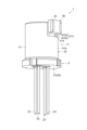
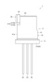
- FIG. 1 is a perspective view of an optical module according to the first embodiment.
- FIG. 2 is a perspective view of the optical module shown in FIG. 1 as viewed from below.
- 3 is an exploded perspective view of the optical module shown in FIG. 1.
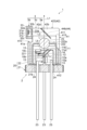
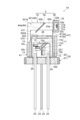
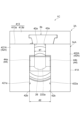
- FIG. 4 is a cross-sectional view of the optical module shown in FIG. 1 along line IV-IV.
- 5 is a front view of the optical module shown in FIG. 1.
- FIG. 6 is a rear view of the optical module shown in FIG. 1.
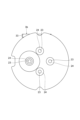
- FIG. 7 is a top view of the optical module shown in FIG. 1.
- FIG. 8 is a bottom view of the optical module shown in FIG. 1.
- FIG. 9 is a right side view of the optical module shown in FIG. 1.
- FIG. 10 is a left side view of the optical module shown in FIG. 1.
- FIG. 10 is a left side view of the optical module shown in FIG. 1.
- FIG. 11 is a bottom view of a monitor unit included in the optical module shown in FIG. 1.
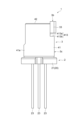
- FIG. FIG. 12 is a perspective view showing an optical module according to the second embodiment.
- 13 is an exploded perspective view of the optical module shown in FIG. 12.
- FIG. 14 is a cross-sectional view of the optical module shown in FIG. 12 taken along line XIV-XIV.
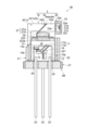
- FIG. 15 is a perspective view showing an optical module according to the third embodiment. 16 is an exploded perspective view of the optical module shown in FIG. 15.
- FIG. 17 is a cross-sectional view of the optical module shown in FIG. 15 along line XVII-XVII.
- FIG. 20 is an exploded perspective view of the optical module shown in FIG. 18.
- FIG. 21 is a cross-sectional view of the optical module shown in FIG. 18 taken along line XXI-XXI.
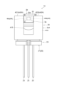
- 22 is a front view of the optical module shown in FIG. 18.
- FIG. 23 is a rear view of the optical module shown in FIG. 18.
- FIG. 24 is a top view of the optical module shown in FIG. 18.
- FIG. 25 is a bottom view of the optical module shown in FIG. 18.
- FIG. 26 is a right side view of the optical module shown in FIG. 18.
- FIG. 27 is a left side view of the optical module shown in FIG. 18.
- FIG. 21 is a cross-sectional view of the optical module shown in FIG. 18 taken along line XXI-XXI.
- 22 is a front view of the optical module shown in
- One object of the present disclosure is to provide a monitor unit that can easily monitor laser light output from a housing that accommodates a semiconductor laser element, and an optical module that includes the monitor unit.
- a monitor unit includes a holder, an optical splitter that splits a laser beam into a first laser beam and a second laser beam, and a photodetector that detects the second laser beam.
- the light branching section and the light detection section are fixed to the holder so that the second laser beam is incident on the light detection section.
- the light branching section and the light detecting section are fixed to the holder in advance while being positioned as described above. Therefore, by attaching a monitor unit to the light source described below, the laser beam can be easily monitored.
- the holder may have a first open end, a second open end, a hollow side wall, and an end wall provided at the first open end.
- a base portion may be formed on the end wall portion to hold the light branching portion in an inclined state with respect to the output direction of the laser beam.
- the photodetector may be attached to the outer surface of the sidewall on the optical path of the second laser beam.
- An optical path may be formed in the side wall portion for passing the second laser beam to the photodetector side.
- the window side of the housing of the light source section can be accommodated inside the side wall section. Since the end wall portion is formed with a base portion that holds the light branching portion, the laser beam output from the window portion is split into the first laser beam and the second laser beam by the light branching portion held by the base portion. can. Since the side wall has an optical path through which the second laser beam passes to the photodetector side, the second laser beam can be detected by the photodetector attached to the side surface of the side wall.
- a notch portion having a first surface perpendicular to the optical path of the second laser beam may be provided on the outer surface of the side wall portion, and the light detection portion may be fixed to the first surface.
- the photodetector By attaching the photodetector to the notch, the photodetector can be easily attached and productivity is improved.
- the side wall portion may have a rectangular outer shape when viewed from the output direction of the laser light.
- the end wall portion has a first end wall portion and a second end wall portion, and the first end wall portion and the second end wall portion are separated from each other across the optical path of the second laser beam. good too.
- the first end wall portion has a first inclined surface that is inclined with respect to the output direction of the laser beam
- the second end wall portion has a second inclined surface that is inclined with respect to the output direction of the laser beam.
- the first inclined surface and the second inclined surface may constitute the base portion.
- the laser beam and the second laser beam can pass therebetween. Since the first slanted surface and the second slanted surface are formed on the first end wall portion and the second end wall portion, it is possible to secure an arrangement area for the light branching portion. By fixing the light branching part to the first inclined surface and the second inclined surface, the light branching part can be arranged in a state of being inclined with respect to the output direction of the laser light.
- the end wall portion may have a first region facing each other across the optical path of the second laser beam, and a second region facing each other across the light branching portion.
- a distance between the second regions may be longer than a distance between the first regions.
- the first inclined surface and the second inclined surface may be surfaces connecting the first region and the second region.
- the photodetector may detect laser light in the visible region.
- the monitor unit is required to monitor visible laser light from the light source. Therefore, the configuration of the monitor unit described above is effective.
- An optical module may include the monitor unit and a light source section to which the monitor unit is attached.
- the light source section may include a semiconductor laser element that outputs the laser light, and a housing that houses the semiconductor laser element and has a window that transmits the laser light.
- the second open end may be fixed to a main surface of a support plate of the housing, and the side wall may accommodate the window inside.
- the optical module includes the monitor unit, it is possible to easily monitor the laser light output from the housing.
- a lens may be provided in the window. This configuration facilitates miniaturization of the light source unit, and as a result, facilitates miniaturization of the optical module.
- a window member having no lens function may be provided in the window portion. This configuration can be applied to an optical system using a divergent beam.
- the housing may have a lens component so as to cover the window, and the window may be provided with a window member having no lens function. With this configuration, any lens component can be attached, and a desired optical system can be realized.
- An optical module further includes a plurality of the semiconductor laser elements, and a combining section for combining the plurality of laser beams output from the plurality of the semiconductor laser elements, wherein the plurality of the semiconductor laser elements and the multiplexing unit may be accommodated in the package.
- a combining section for combining the plurality of laser beams output from the plurality of the semiconductor laser elements, wherein the plurality of the semiconductor laser elements and the multiplexing unit may be accommodated in the package.
- the plurality of laser beams may include red laser beams, blue laser beams, and green laser beams.
- the light module functions as a trichromatic light source.
- the optical module may have an optical fiber and a ferrule. With this configuration, the laser light can be optically coupled to the optical fiber, and the overall size of the optical module can be reduced.
- FIG. 1 is a perspective view of an optical module according to the first embodiment.
- FIG. 2 is a perspective view of the optical module shown in FIG. 1 as viewed from below in FIG. 3 is an exploded perspective view of the optical module shown in FIG. 1.
- FIG. FIG. 4 is a cross-sectional view of the optical module shown in FIG. 1 along line IV-IV. 5 is a front view of the optical module shown in FIG. 1.
- FIG. 6 is a rear view of the optical module shown in FIG. 1.
- FIG. 7 is a top view of the optical module shown in FIG. 1.
- FIG. 8 is a bottom view of the optical module shown in FIG. 1.
- FIG. FIG. 9 is a right side view of the optical module shown in FIG. 1, and shows the optical module when viewed from the right side in FIG.
- FIG. 10 is a left side view of the optical module shown in FIG. 1, and shows the optical module when viewed from the left side in FIG.
- FIG. 11 is a diagram of the monitor unit included in the optical module shown
- the optical module 1A has a light source section 2 for outputting laser light L and a monitor unit 3 for detecting part of the laser light L output from the light source section 2 .
- the light source unit 2 outputs laser light L.
- the light source unit 2 is a light source module capable of outputting laser light L in the visible range.
- the light source unit 2 is a light source module capable of outputting laser light L including at least one of red laser light Lr, green laser light Lg, and blue laser light Lb.
- the light source unit 2 is, for example, a CAN-type light source module.
- the light source section 2 includes a first LD (first semiconductor laser element) 10a, a second LD (second semiconductor laser element) 10b, a third LD (third semiconductor laser element) 10c, a combining section 11, and a housing 20. and
- the first LD 10a is a semiconductor laser element that outputs red laser light Lr.
- An example of the oscillation wavelength (or center wavelength) of the red laser light Lr is 620 nm or more and 650 nm or less.
- the second LD 10b is a semiconductor laser element that outputs green laser light Lg.
- An example of the oscillation wavelength (or center wavelength) of the green laser light Lg is 510 nm or more and 540 nm or less.
- the third LD 10c is a semiconductor laser element that outputs blue laser light Lb.
- An example of the oscillation wavelength (or center wavelength) of the blue laser light Lb is 435 nm or more and 465 nm or less.
- Examples of the first LD 10a, second LD 10b and third LD 10c are laser diode chips (LD chips).
- the first LD 10a, the second LD 10b and the third LD 10c are mounted on the support plate 12.
- the first LD 10a, the second LD 10b, and the third LD 10c may be mounted on the support plate 12 via a base portion 13 (for example, a submount).
- Examples of materials for the support plate 12 are metals and ceramics.
- a material having a thermal expansion coefficient close to that of the semiconductor material forming the first LD 10a, the second LD 10b, and the third LD 10c can be used.
- AlN, SiC, Si, or diamond can be used.
- the second LD 10b and the third LD 10c are arranged laterally with respect to the optical axis of the first LD 10a.
- the second LD 10b and the third LD 10c are arranged on the same side with respect to the optical axis of the first LD 10a.
- the second LD 10b and the third LD 10c are arranged on the same side with respect to the output direction of the red laser light Lr from the first LD 10a, and the green laser light Lg and the blue laser light Lb from the second LD 10b and the third LD 10c. , intersects the output direction of the red laser light Lr (substantially orthogonal in FIG. 4).
- the optical axis of the first LD 10a coincides with the optical axis A of the light source section 2 (see FIG. 3). That is, the output direction of the laser light L from the light source unit 2 matches the output direction of the red laser light Lr.
- the multiplexing unit 11 is configured to be able to multiplex the red laser light Lr, the green laser light Lg, and the blue laser light Lb. An example of the multiplexing unit 11 will be described based on the multiplexing unit 11 shown in FIG.
- the combining unit 11 has a filter 11a and a filter 11b.
- the filters 11a and 11b are, for example, wavelength selective filters.
- filters 11a and 11b have multilayer filters (eg, dielectric multilayer filters) formed on transparent substrates.
- An example of a transparent substrate is a glass plate.
- the transparent substrate may also be part of filters 11a and 11b.
- the filter 11a transmits the red laser light Lr and reflects the green laser light Lg from the second LD 10b toward the filter 11b. Thereby, the red laser beam Lr and the green laser beam Lg are combined.
- Filter 11b transmits combined light of red laser light Lr and green laser light Lg (that is, red laser light Lr and green laser light Lg), and reflects blue laser light Lb from third LD 10c to the opposite side of filter 11a. .
- the laser light L is obtained as a combined light in which the red laser light Lr, the green laser light Lg and the blue laser light Lb are combined.
- the red laser light Lr, the green laser light Lg, and the blue laser light Lb are all output. However, if any one of the red laser beam Lr, the green laser beam Lg, and the blue laser beam Lb is not output, the laser beam L is light obtained by combining the laser beams of the colors being output.
- the filters 11a and 11b are mounted on the support plate 12 while being arranged so as to generate combined light of the red laser light Lr, the green laser light Lg and the blue laser light Lb. At least one of the filter 11 a and the filter 11 b may be mounted on the support plate 12 via the base portion 14 .
- the housing 20 accommodates the first LD 10a, the second LD 10b and the third LD 10c. As shown in FIGS. 3 and 4, housing 20 has support plate 21 and cover 22 . In this embodiment, the housing 20 is a CAN type housing.
- the support plate 21 is a member to which the support plate 12 on which the first LD 10a, the second LD 10b, the third LD 10c and the wave combining section 11 are mounted is fixed.
- the support plate 12 is fixed to the support plate 21 so that the main surface 12a of the support plate 12 and the main surface 21a of the support plate 21 are perpendicular to each other.
- the laser light L is output in the normal direction of the main surface 21 a of the support plate 21 .
- Support plate 21 is, for example, a disk-shaped member.
- An example of the support plate 21 is a stem. Examples of materials for the support plate 21 are metal and ceramic.
- a plurality of conductive members 23 are passed through the support plate 21 in the thickness direction.
- four conductive members 23 are passed through the support plate 21 .
- Each conductive member 23 is a bar-shaped member extending in one direction, and is, for example, a lead pin.
- Each conductive member 23 protrudes toward the main surface 21 a of the support plate 21 .
- the plurality of conductive members 23 are used for power supply to the first LD 10a, second LD 10b and third LD 10c, GND lines, and the like.
- An insulating member 24 is arranged around a portion of each conductive member 23 located inside the support plate 21 to prevent a short circuit between the conductive member 23 and the support plate 21 .
- the cover 22 includes a hollow side wall portion 221 with both ends open, and an end wall portion 222 closing one of the open ends.
- a flange portion may be formed at the end portion of the side wall portion 221 on the side of the support plate 21 .
- the cover 22 may be a cap (CAN cap) on the CAN-type housing 20 .
- the open ends that are not blocked by the end walls 222 are fixed to the support plate 21 .
- the cover 22 and the support plate 21 form an accommodation space that accommodates, for example, the first LD 10a, the second LD 10b, and the third LD 10c.
- the end wall portion 222 is hermetically sealed to the support plate 21, for example.
- the end wall portion 222 is formed with an opening (window portion) 222a through which the laser beam L passes.
- the laser light L is output to the outside of the housing 20 through the opening 222a.
- the lens 25 is fitted in the opening 222a.
- the lens 25 is a lens that converts the laser light L into convergent light, and is, for example, a ball lens.
- the monitor unit 3 is a unit for detecting part of the laser light L output from the opening 222a.
- the monitor unit 3 has a light branching portion 3a, a light detecting portion 3b, and a holder 3c.
- the light branching portion 3a is arranged to be inclined with respect to the output direction of the laser light L from the opening 222a (the direction of the optical axis A of the light source portion 2). In this embodiment, unless otherwise specified, the angle of inclination of the light branching portion 3a with respect to the output direction of the laser light L is 45 degrees.
- the light splitter 3a splits the laser beam L into a first laser beam L1 and a second laser beam L2.
- the first laser beam L1 is a portion of the laser beam L that travels along the output direction of the laser beam L, and is output light from the optical module 1.
- the second laser beam L2 is a portion of the laser beam L that travels in a direction different from the output direction of the laser beam L.
- the second laser beam L2 is light obtained by partially reflecting the laser beam L at the light branching portion 3a.
- the second laser light L2 is light (monitor light) for checking whether or not the red laser light Lr, the green laser light Lg, and the blue laser light Lb are output from the first LD 10a, the second LD 10b, and the third LD 10c in a desired output state. light).
- the first laser beam L1 is output light from the optical module 1, and the second laser beam L2 is light for inspection. Therefore, the amount of light of the first laser beam L1 is greater than that of the second laser beam L2.
- An example of the reflectance of the laser light L at the light branching portion 3a is 5% to 15%.
- An example of the light branching portion 3a is a glass plate.
- the second laser beam L2 is obtained by Fresnel reflection on the surface of the glass plate.
- the photodetector 3b is arranged on the optical path of the second laser beam L2.
- the photodetector 3b includes at least one of a first photodetector 31a, a second photodetector 31b, and a third photodetector 31c arranged in parallel. Examples of the first photodetector 31a, the second photodetector 31b and the third photodetector 31c are photodiodes.
- a first filter 32a, a second filter 32b and a third filter 32c are arranged on the incident surface side of the second laser beam L2 in the first photodetector 31a, the second photodetector 31b and the third photodetector 31c. ing.
- the first filter 32a, the second filter 32b, and the third filter 32c are filters that selectively pass the red laser light Lr, the green laser light Lg, and the blue laser light Lb.
- the first photodetector 31a detects the red laser beam Lr of the second laser beam L2
- the second photodetector 31b detects the green laser beam Lg of the second laser beam L2.
- the third photodetector 31c detects the blue laser light Lb of the second laser light L2.
- the first photodetector 31a, the second photodetector 31b, and the third photodetector 31c are electrically connected to a control device (not shown).
- the controller converts the laser light L into red laser light Lr, green laser light Lg and blue laser light Lb according to the detection results of the first photodetector 31a, the second photodetector 31b and the third photodetector 31c. controls the first LD 10a, the second LD 10b, and the third LD 10c so that is in a desired state (desired amount of light, etc.).
- the photodetector 3b has a housing 33 that accommodates the first photodetector 31a, the second photodetector 31b, and the third photodetector 31c.
- a window portion 33a for passing the second laser beam L2 is formed in the wall of the housing 33 on the incident side of the second laser beam L2.
- the window portion 33 a can be configured by fitting a transparent window member (for example, a glass plate) or the like into an opening formed in the housing 33 .
- An example of the shape of the window portion 33a is rectangular as shown in FIG.
- the shape of the window portion 33a may be square or circular.
- the number of photodetectors included in the photodetector 3b may be one.
- the incident surface of the second laser beam L2 in the photodetector is virtually divided into a first area, a second area and a third area, and the red laser beam L2 is detected in the first area, the second area and the third area.
- Light Lr, green laser light Lg and blue laser light Lb are detected.
- a first filter 32a, a second filter 32b and a third filter 32c are arranged for the first area, the second area and the third area.
- the holder 3c is a member to which the light branching part 3a and the light detection part 3b are fixed, and is attached to the housing 20.
- the holder 3 c functions as an adapter for arranging the light branching section 3 a and the light detecting section 3 b with respect to the light source section 2 .
- the holder 3 c has a hollow side wall portion 41 (hollow body) and an end wall portion 42 .
- the side wall portion 41 is a hollow member (hollow body) capable of accommodating the portion of the housing 20 on the side of the opening 222a.
- the side wall portion 41 accommodates the window portion 33a inside.
- the side wall portion 41 is cylindrical.
- An example of the material of the side wall portion 41 is metal (for example, stainless steel (SUS)).
- An example of sidewall 41 is a cylindrical metal sleeve.
- the side wall portion 41 has a first open end portion 411 and a second open end portion 412 .
- the second open end 412 is the end opposite to the first open end 411 .
- the side wall portion 41 is fixed to the housing 20 by joining the second open end portion 412 to the main surface 21 a of the support plate 21 of the housing 20 .
- the side wall portion 41 can be fixed to the support plate 21 by, for example, resistance welding or laser welding.
- the side wall portion 41 may be bonded to the support plate 21 with an adhesive, or may be bonded to the support plate 21 using solder.
- a step portion (or notch portion) 413 recessed toward the central axis side of the side wall portion 41 is formed on the first open end portion 411 side of the outer surface 41 a of the side wall portion 41 .
- the stepped portion 413 functions as a portion (photodetector mounting portion) on which the photodetector 3b is mounted.
- the stepped portion 413 has a first surface 413a that intersects the optical path of the second laser beam L2, and a second surface 413b that intersects the first surface 413a.
- the first surface 413a is orthogonal to the optical path of the second laser beam L2
- the second surface 413b is orthogonal to the first surface 413a.
- the first surface 413a is a surface to which the photodetector 3b is fixed, and in one embodiment, the first surface 413a is a flat surface.
- a recess 414 recessed from the first open end 411 toward the second open end 412 is formed in a portion of the side wall portion 41 (specifically, the portion where the stepped portion 413 is formed). .
- the recess 414 functions as an optical path for passing the second laser beam L2.
- a recessed portion 415 recessed from the first open end portion 411 toward the second open end portion 412 may be formed in the side wall portion 41 in a region facing the recessed portion 414 .
- the form in which the concave portion 415 is formed will be described.
- the end wall portion 42 is provided at the first open end portion 411 .
- a base portion 44 is formed on the end wall portion 42 to hold the light branching portion 3a in an inclined state with respect to the output direction of the laser light L from the opening 222a.
- An example of the end wall portion 42 will be specifically described.
- the end wall portion 42 has a first end wall portion 421 and a second end wall portion 422 . As shown in FIG. 7, the first end wall portion 421 and the second end wall portion 422 are spaced apart so as to sandwich the optical path (or recess 414) of the second laser beam L2. In FIG. 7, the second laser beam L2 is indicated by a dashed line to indicate the optical path of the second laser beam L2.
- the first end wall portion 421 has a first stepped portion 421a toward the second end wall portion 422 for securing an arrangement area for the light branching portion 3a.
- the first stepped portion 421 a is a portion of the first end wall portion 421 that is recessed away from the second end wall portion 422 .
- the first end wall portion 421 has a first step surface (first inclined surface) 44a that is inclined with respect to the output direction of the laser light L. As shown in FIG.
- the second end wall portion 422 has a second stepped portion 422a toward the first end wall portion 421 for securing an arrangement area for the light branching portion 3a.
- the second stepped portion 422 a is a recessed portion away from the first end wall portion 421 .
- the second end wall portion 422 has a second stepped surface (second inclined surface) 44b that is inclined with respect to the output direction of the laser light L. As shown in FIG.
- the inclination angle of the second step surface 44b with respect to the output direction of the laser beam L is the same as the inclination angle of the first step surface 44a with respect to the output direction of the laser beam L.
- the surfaces facing each other of the first end wall portion 421 and the second end wall portion 422 have the first region 42a and the second region 42b.
- the first regions 42a face each other across the optical path of the second laser beam L2.
- the second regions 42b face each other with the light branching portion 3a interposed therebetween.
- the first region 42a is closer to the photodetector 3b than the second region 42b.
- the distance d2 between the second regions 42b of the first end wall 421 and the second end wall 422 is equal to the distance d2 between the first regions 42a of the first end wall 421 and the second end wall 422. longer than the distance d1 between The distance d2 is a length that allows the optical branching portion 3a to be arranged between the second regions 42b of the first end wall portion 421 and the second end wall portion 422.
- FIG. 7 shows that allows the optical branching portion 3a to be arranged between the second regions 42b of the first end wall portion 421 and the second end wall portion 422.
- a surface connecting the first region 42a and the second region 42b in the first end wall portion 421 is inclined with respect to the output direction of the laser light L and corresponds to the first stepped surface 44a.
- a surface connecting the first region 42a and the second region 42b in the second end wall portion 422 is inclined with respect to the output direction of the laser light L and corresponds to the second stepped surface 44b.
- the optical splitter 3a is fixed to the first step surface 44a and the second step surface 44b. That is, the first stepped surface 44 a and the second stepped surface 44 b function as the base portion 44 . Therefore, the optical branching portion 3a is formed so as to be positioned on the optical path of the laser beam L. As shown in FIG. When the light branching portion 3a has a plate shape such as a glass plate, the inclination angles of the first step surface 44a and the second step surface 44b substantially match the inclination angle of the light branching portion 3a with respect to the output direction of the laser light L. do.
- the light branching portion 3a can be fixed to the first step surface 44a and the second step surface 44b using an adhesive or solder.
- the light branching portion 3a and the light detecting portion 3b are fixed to the holder 3c.
- the photodetector 3b detects the second laser beam L2 from the optical branch 3a. Therefore, the stepped portion 413 for fixing the light detection portion 3b and the base portion 44 (specifically, the first stepped surface 44a and the second stepped surface 44b) to which the light branching portion 3a is fixed are the second laser beams.
- the light branching portion 3a and the light detecting portion 3b are formed so as to be held in alignment with each other by the holder 3c so that L2 is incident on the light detecting portion 3b.
- the holder 3c can be manufactured as follows. First, a first member having a side wall portion 41 and an end wall portion that completely closes the first open end portion 411 of the side wall portion 41 is manufactured.
- the first member can be manufactured by, for example, an NC lathe. After that, by processing the first member, for example, the stepped portion 413 for arranging the light detection portion 3b, the first stepped portion 421a and the second stepped portion 422a (the base portion 44) for arranging the light branching portion 3a. including ).
- the holder 3c is thus obtained.
- the light branching portion 3a is fixed to the base portion 44 (specifically, the first step surface 44a and the second step surface 44b), and the light detection portion 3b is fixed to the step portion 413. .
- the monitor unit 3 is obtained.
- the window portion 33 a and the cover 22 can be accommodated inside the side wall portion 221 . Since the light branching portion 3a is held on the base portion 44 formed on the end wall portion 42, the laser light L is incident on the light branching portion 3a by accommodating the window portion 33a and the cover 22 inside the side wall portion 41. do. Therefore, the laser light L can be split into the first laser light L1 and the second laser light L2 at the light splitter 3a.
- the side wall portion 41 is formed with the concave portion 414 for passing the second laser beam L2, even if the photodetector portion 3b is fixed to the outer surface 41a of the side wall portion 41, the photodetector portion 3b can be detected by the second laser beam L2. Laser light L2 can be detected.
- the light branching portion 3a and the light detecting portion 3b are aligned with respect to the side wall portion 41 and fixed. Therefore, by covering the cover 22 with the side wall portion 41 and fixing it to the support plate 21, the positions of the light branching portion 3a and the light detecting portion 3b with respect to the light source portion 2 are automatically determined. Therefore, when the laser light L output from the light source unit 2 is monitored outside the light source unit 2, the light detection unit 3b can be easily arranged. can be monitored.
- the inclination angle of the light branching portion 3a is fixed, and the light branching portion 3a has a sufficient size to branch the laser light L. Therefore, the laser beam L can be split into the first laser beam L1 and the second laser beam L2 even if the laser beam L does not necessarily pass through the center of the optical splitter 3a, and the second laser beam L2 can be detected by the photodetector 3b. It is possible.
- the first end wall portion 421 and the second end wall portion 422 are separated from each other across the optical path of the second laser beam L2.
- the laser light L and the second laser light L2 can pass between the second end wall portions 422 . Since the first end wall portion 421 and the second end wall portion 422 are formed with the first stepped portion 421a and the second stepped portion 422a, the arrangement area for the light branching portion 3a can be secured. Since the first stepped surface 44a and the second stepped surface 44b are inclined surfaces, the light branching portion 3a is arranged in a state inclined with respect to the output direction of the laser light L by fixing the light branching portion 3a to them. It is possible.
- the area from the arrangement position of the light branching portion 3a to the recess 415 in the monitor unit 3 is open as shown in FIG. Therefore, it is easy to fix the optical branching portion 3 a to the base portion 44 .
- the light source section 2 does not have a light detection section for monitoring the light output states of the first LD 10a, the second LD 10b and the third LD 10c. Even with such a light source unit 2, by covering the cover 22 with the monitor unit 3 and fixing it to the support plate 21, the light detection unit 3b can be easily aligned with the light source unit 2 as described above, and then the laser beam can be detected. Part of the light L (second laser light L2) can be detected. As a result, the first LD 10a, the second LD 10b and the third LD 10c can be controlled to desired output states.
- the optical module 1 there is no need to dispose a photodetector for monitoring the optical output states of the first LD 10a, the second LD 10b, and the third LD 10c inside the housing 20. Therefore, the light source section 2 can be miniaturized, and as a result, the optical module 1 can be miniaturized.
- the configuration of the optical module 1 and the monitor unit 3 is effective when the optical module 1 is mounted on a wearable device such as smart glasses.
- the lens 25 is attached to the cover 22 in the optical module 1 described in this embodiment. Therefore, for example, it is not necessary to arrange a lens or the like for condensing laser light or collimating the laser light in the housing space of the first LD 10a, the second LD 10b, and the third LD 10c inside the cover 22. FIG. In this respect as well, the size of the light source unit 2 can be reduced.
- the design of the light source unit 2 is easy, and when the photodetector is provided Necessary optical axis adjustment is also unnecessary. Therefore, the light source section 2 can be easily manufactured, and as a result, the optical module 1 can be easily manufactured.
- the optical module 1 monitors, for example, a CAN light source module (light source unit 2 in this embodiment) that does not have a photodetector for monitoring the light output states of the first LD 10a, the second LD 10b, and the third LD 10c as described above. It can be manufactured easily by attaching the unit 3 . Therefore, it is easy to manufacture the optical module 1 .
- a CAN light source module light source unit 2 in this embodiment
- a laser diode that outputs laser light in the visible region
- the light output of the laser light output forward and backward is not in a proportional relationship. Therefore, when monitoring the laser light in the visible region output from the LD, it is necessary to divide the laser light output forward by the light splitter and detect it with the photodetector. Therefore, if a photodetector for monitoring the output state of the red laser light Lr, the green laser light Lg, and the blue laser light Lb output from the first LD 10a, the second LD 10b, and the third LD 10c is arranged in the light source unit 2, light detection In addition to the device, the light branching section is also arranged within the light source section 2 .
- the photodetector 30 for monitoring can be arranged outside the light source 2, so that the light source 2 can be miniaturized.
- the optical module 1 and the monitor unit 3 are effective when the light source section 2 includes an LD that outputs laser light in the visible region.
- the light source unit 2 does not have a photodetector, while the monitor unit 3 has a photodetector 3b. Therefore, it is not necessary to pass the conductive member 23 for light detection through the support plate 21 of the housing 20 . That is, the number of conductive members 23 passed through the support plate 21 can be reduced. Since the monitor unit 3 includes the photodetector 3b, it is easy to use, for example, a flexible printed circuit board (FPC). Since the monitor unit 3 includes the photodetector 3b, it is easy to replace the photodetector 3b.
- FPC flexible printed circuit board
- the laser light L can include the red laser light Lr, the green laser light Lg, and the blue laser light Lb. Therefore, the optical module 1 including the light source section 2 can be used as a three-color light source module.
- FIG. 12 is a perspective view showing another embodiment of the optical module.
- 13 is an exploded perspective view of the optical module shown in FIG. 12.
- FIG. 14 is a cross-sectional view of the optical module shown in FIG. 12 taken along line XIV-XIV.
- the optical module 1A shown in FIGS. 12 to 14 has a light source section 2A and a monitor unit 3.
- the light source section 2A differs from the light source section 2 mainly in that the aperture 222a does not have a lens and that the window member 26 having no lens function is attached to the aperture 222a. Since the configuration of the optical module 1A is the same as that of the optical module 1 other than these points of difference, the above points of difference will be explained, and the explanation of other configurations will be omitted.
- the window member 26 is fixed to the inner surface of the end wall portion 222 so as to close the opening 222a of the end wall portion 222 of the cover 22 from the inside.
- An example of the window member 26 is a glass plate.
- the window member 26 may be fitted in the opening 222a.
- the window member 26 may be fixed to the outer surface of the end wall portion 222 so as to block the opening 222a of the cover 22 from the outside. In a configuration having a window member 26, the window member 26 can be part of the window as well as the opening 222a.
- the configuration of the optical module 1A is the same as that of the optical module 1 except that it has a light source unit 2A instead of the light source unit 2. Further, the light source section 2A has the same configuration as the light source section 2 except that it does not have the lens 25 and the window member 26 is attached to the opening 222a. Therefore, the optical module 1A has effects similar to those of the optical module 1.
- FIG. 1 The configuration of the optical module 1A is the same as that of the optical module 1 except that it has a light source unit 2A instead of the light source unit 2. Further, the light source section 2A has the same configuration as the light source section 2 except that it does not have the lens 25 and the window member 26 is attached to the opening 222a. Therefore, the optical module 1A has effects similar to those of the optical module 1. FIG.
- FIG. 15 is a perspective view showing an optical module according to the third embodiment.
- 16 is an exploded perspective view of the optical module shown in FIG. 15.
- FIG. 17 is a cross-sectional view of the optical module shown in FIG. 15 along line XVII-XVII.
- the optical module 1B shown in FIGS. 15 to 17 has a light source section 2B and a monitor unit 3.
- the light source section 2 is mainly similar to the light source section 2 in that the window member 26 having no lens function is attached to the opening 222a and the lens component is attached to the outer surface of the end wall section 222 in place of the lens 25. differ. Since the configuration of the optical module 1B other than these differences is the same as that of the optical module 1, the above differences will be explained and the explanation of other configurations will be omitted.
- the window member 26 covers the inner surface of the end wall portion 222 so as to close the opening 222a of the cover 22 from the inside. is fixed to An example of the window member 26 is a glass plate.
- the window member 26 may be fitted in the opening 222a.
- the lens component 27 has a lens 27a.
- the lens component 27 may have a holder 27b that holds the lens 27a.
- the lens 27a is fixed to the outer surface of the end wall portion 222 while being fitted in the holder 27b.
- Lens 27 a is provided to cover window member 26 .
- the holder 27b may be fixed to the end wall portion 222 via a plate-like base portion 28. As shown in FIG. In this case, the base portion 28 is formed with an opening corresponding to the opening 222a.
- An example of the lens 27a is a collimating lens that collimates the first laser beam L1.
- the lens component 27 may have, for example, a plurality of lenses, and the plurality of lenses may realize a collimating function.
- the lens component 27 may have a function of converting the first laser beam L1 into light other than collimated light (for example, convergent light).
- the configuration of the optical module 1B is the same as that of the optical module 1 except that it has a light source unit 2B instead of the light source unit 2. Furthermore, the light source section 2B has the same features as the light source except that the window member 26 having no lens function is attached to the opening 222a and the lens component 27 is attached to the outer surface of the end wall section 222 instead of the lens 25.
- the configuration is the same as that of Part 2. Therefore, the optical module 1B has effects similar to those of the optical module 1A.
- the collimated laser beam L is output from the light source unit 2B. Therefore, the first laser beam L1 as collimated light can also be output from the optical module 1B.
- FIG. 18 is a perspective view showing the optical module according to the fourth embodiment.
- 19 is a perspective view of the optical module shown in FIG. 18 as viewed from below in FIG. 18.
- FIG. 20 is an exploded perspective view of the optical module shown in FIG. 18.
- FIG. 21 is a cross-sectional view of the optical module shown in FIG. 18 taken along line XXI-XXI.
- 22 is a front view of the optical module shown in FIG. 18.
- FIG. 23 is a rear view of the optical module shown in FIG. 18.
- FIG. 24 is a top view of the optical module shown in FIG. 18.
- FIG. 25 is a bottom view of the optical module shown in FIG. 18.
- FIG. 26 is a right side view of the optical module shown in FIG. 18.
- FIG. 27 is a left side view of the optical module shown in FIG. 18.
- FIG. 18 is a perspective view showing the optical module according to the fourth embodiment.
- 19 is a perspective view of the optical module shown in FIG. 18 as viewed from below
- the optical module 1C shown in FIGS. 18 to 27 has a light source section 2A and a monitor unit 3A.
- the light source unit 2A included in the optical module 1C is the same as the light source unit 2A described in the second embodiment, so description thereof will be omitted.
- the monitor unit 3A has a light branching section 3a, a light detection section 3b and a holder 3cA. Since the configurations of the light branching section 3a and the light detecting section 3b are the same as those of the monitor unit 3 described in the first embodiment, description thereof will be omitted.
- the holder 3cA mainly differs from the holder 3c described in the first embodiment in that it has a side wall portion 41A instead of the side wall portion 41.
- the side wall portion 41A in the fourth embodiment has a square shape (for example, a square or a rectangle) when viewed from the output direction of the laser light L. , and is different from the side wall portion 41 .
- An example of the side wall portion 41A is a rectangular sleeve having a rectangular outer shape.
- the side wall portion 41A has a first open end portion 411 and a second open end portion 412 similarly to the side wall portion 41, and is hollow so as to accommodate the opening 222a side of the housing 20 (the portion of the cover 22).
- the inner surface shape of the side wall portion 41A when viewed from the output direction of the laser beam L is circular corresponding to the shape of the cover 22, but may be square if the cover 22 portion can be accommodated.
- the side wall portion 41A has a second open end portion 412 fixed to the support plate 21 in the same manner as in the first embodiment.
- the side wall portion 41A is formed with a stepped portion 413 for attaching the photodetecting portion 3b and a concave portion 414 for passing the second laser beam L2. Since the outer shape of the side wall portion 41A is rectangular as described above, the stepped portion 413 can also be a notch portion formed by notching a corner formed by one side surface 41b of the side wall portion 41A and the end wall portion 42A. be.
- a recess 415 may be formed in the side wall portion 41A on the opposite side of the recess 414 as in the case of the side wall portion 41A. The formation of the recessed portion 415 makes it easy to attach the light branching portion 3a to the side wall portion 41A.
- An end wall portion 42A is provided at the first open end portion 411 of the side wall portion 41A.
- the end wall portion 42A has the same configuration as the end wall portion 42 except that the shape of the boundary portion between the end wall portion 42A and the side wall portion 41A differs from that in the first embodiment according to the shape of the side wall portion 41A. . Therefore, the end wall portion 42A is formed with a base portion 44 for holding the light branching portion 3a.
- the end wall portion 42A may have a first end wall portion 421A and a second end wall portion 422A.
- the arrangement state of the first end wall portion 421A and the second end wall portion 422A is the same as the case of the first end wall portion 421 and the second end wall portion 422 in the first embodiment.
- the configuration of the first end wall portion 421A and the second end wall portion 422A depends on the shape of the side wall portion 41A, the shape of the boundary portion between the side wall portion 41A and the first end wall portion 421A, and the shape of the boundary portion between the side wall portion 41A and the second end wall portion.
- first end wall portion 421 and the second end wall portion 422 The same as the first end wall portion 421 and the second end wall portion 422 except that the shape of the boundary portion with the portion 422A is different from that of the first end wall portion 421 and the second end wall portion 422 in the first embodiment. is. Therefore, description of the first end wall portion 421A and the second end wall portion 422A is omitted.
- the optical module 1C is the same as the optical module 1A according to the second embodiment except that the monitor unit 3A is used instead of the monitor unit 3.
- the configuration of the monitor unit 3A is substantially the same as that of the monitor unit 3, except that the side wall 41A has a rectangular outer shape when viewed from the output direction of the laser light L. As shown in FIG. Therefore, the optical module 1C has effects similar to those of the optical module 1A (corresponding to effects similar to those of the optical module 1).
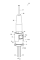
- FIG. 28 is a perspective view showing an optical module according to the fifth embodiment.
- 29 is an exploded perspective view of the optical module shown in FIG. 28.
- the optical module 1D shown in FIGS. 28 and 29 is a pigtail-type optical module having an optical output section 4, an optical transmission medium 50, and a ferrule holder 60.
- FIG. 1D is a pigtail-type optical module having an optical output section 4, an optical transmission medium 50, and a ferrule holder 60.
- the optical output unit 4 is the optical module 1 according to the first embodiment, and outputs the first laser beam L1. That is, the light output section 4 has a light source section 2 and a monitor unit 3 , and the monitor unit 3 is fixed to the light source section 2 .
- the configurations of the light source section 2 and the monitor unit 3 are the same as in the first embodiment. Therefore, description of the light source unit 2 and the monitor unit 3 is omitted.
- the optical output section 4, the ferrule holder 60, and the optical transmission medium 50 are arranged along the optical axis A of the optical output section 4 (the axis along the output direction of the first laser beam L1). ing.
- the optical transmission medium 50 receives the first laser light L1 output from the optical output section 4.
- the optical transmission medium 50 has an optical fiber 51 and a ferrule 52 .
- the ferrule 52 is a hollow rod-shaped member.
- the ferrule 52 holds the optical fiber 51 by inserting the optical fiber 51 into the ferrule 52 .
- An example of a material for ferrule 52 is metal.
- a flange portion 53 (or a skirt portion) that defines the amount of insertion of the ferrule 52 into the ferrule holder 60 may be provided on the outer periphery of the end portion 52a of the ferrule 52 on the ferrule holder 60 side.
- the flange portion 53 may be integrated with the ferrule 52 .
- a protective cover 54 may be attached to the ferrule 52 together with the ferrule 52 to protect the ferrule 52 near the insertion port for the optical fiber 51 (the end opposite to the ferrule holder 60).
- Protective cover 54 is, for example, a rubber boot and covers ferrule 52 .
- the ferrule holder 60 has a side wall portion 61 and an end wall portion 62 .
- the ferrule holder 60 is a member that attaches the ferrule 52 to the optical output section 4 (optical module 1).
- the ferrule holder 60 can also function as a member for aligning the optical axis of the optical fiber 51 and the optical axis of the optical output section 4 .
- the shape of the side wall portion 61 is hollow with both ends open.
- the side wall portion 61 covers the side wall portion 41 of the monitor unit 3 included in the light output portion 4 .
- the side wall portion 61 can accommodate the side wall portion 41 inside, and by covering the side wall portion 41 with the side wall portion 61, the optical axis of the optical fiber 51 and the optical axis of the light output portion 4 can be aligned. It is sufficient if it has a shape.
- the side wall portion 61 may also be cylindrical.
- the inner diameter of the side wall portion 61 substantially matches the outer diameter of the side wall portion 41 .
- a part of the side wall portion 61 is formed with a concave portion 61a recessed from the open end on the side of the light output portion 4 toward the opposite side in order to avoid interference with the light detection portion 3b.
- the end wall portion 62 is provided so as to block the open end portion of the side wall portion 61 on the optical transmission medium 50 side.
- the end wall portion 62 is formed with an opening 62a through which the first laser beam L1 passes and in which the end portion 52a of the ferrule 52 is fitted.
- the inner diameter of opening 62a substantially matches the outer diameter of end 52a.
- the opening 62a is formed at a position where the optical axis A of the optical output section 4 and the optical axis of the optical fiber 51 are aligned with the ferrule holder 60 covering the side wall 221 and the end portion 52a being fitted in the opening 62a. ing.
- the optical axis A of the light output section 4 can be aligned with the optical axis of the optical fiber 51 by covering the side wall portion 41 with the ferrule holder 60 after the end portion 52a of the ferrule 52 is fitted in the opening 62a. can.
- the optical module 1D includes an optical output section 4 which is the optical module 1 of the first embodiment. Therefore, the optical module 1D has effects similar to those of the optical module 1 and the monitor unit 3. FIG. 1
- the number of semiconductor laser elements included in the light source section may be one or two.
- the number of semiconductor laser elements included in the light source may be four or more.
- a semiconductor laser element is not limited to a laser diode.
Landscapes
- Physics & Mathematics (AREA)
- General Physics & Mathematics (AREA)
- Electromagnetism (AREA)
- Condensed Matter Physics & Semiconductors (AREA)
- Computer Hardware Design (AREA)
- Engineering & Computer Science (AREA)
- Optics & Photonics (AREA)
- Microelectronics & Electronic Packaging (AREA)
- Power Engineering (AREA)
- Optical Couplings Of Light Guides (AREA)
- Photo Coupler, Interrupter, Optical-To-Optical Conversion Devices (AREA)
- Optical Head (AREA)
- Semiconductor Lasers (AREA)
Abstract
A monitoring unit (3) comprises: a holder (3c); a light branching unit (3a) that branches laser light into first laser light and second laser light; and a light detecting unit (3b) that detects the second laser light. The light branching unit (3a) and the light detecting unit (3b) are fixed to the holder (3c) so that the second laser light enters the light detecting unit (3b).
Description
本開示は、モニタユニットおよび光モジュールに関する。本出願は、2021年11月10日出願の日本出願第2021-183153号に基づく優先権を主張し、前記日本出願に記載された全ての記載内容を援用するものである。
The present disclosure relates to monitor units and optical modules. This application claims priority based on Japanese application No. 2021-183153 filed on November 10, 2021, and incorporates all the descriptions described in the Japanese application.
レーザダイオードのような半導体レーザ素子と、上記半導体レーザ素子を収容する筐体とを備えた光源が知られている。半導体レーザ素子を使用する場合、通常、所望の出力状態を維持するために、レーザ光の一部をモニタする。前述したように、半導体レーザ素子が筐体内に収容されている場合、筐体から外部に出力されたレーザ光の一部をビームスプリッタなどで分離し、分離されたレーザ光を光検出器で検出することが考えられる(特許文献1,2参照)。
A light source is known that includes a semiconductor laser element such as a laser diode and a housing that accommodates the semiconductor laser element. When using a semiconductor laser device, a portion of the laser light is usually monitored in order to maintain the desired output state. As described above, when a semiconductor laser element is housed in a housing, part of the laser light output from the housing to the outside is separated by a beam splitter or the like, and the separated laser light is detected by a photodetector. It is conceivable to do (see Patent Documents 1 and 2).
一実施形態に係るモニタユニットは、ホルダと、レーザ光を第1レーザ光と第2レーザ光に分岐する光分岐部と、前記第2レーザ光を検出する光検出部と、を備える。前記光分岐部および前記光検出部は、前記第2レーザ光が前記光検出部に入射するように前記ホルダに固定されている。
A monitor unit according to one embodiment includes a holder, an optical splitter that splits a laser beam into a first laser beam and a second laser beam, and a photodetector that detects the second laser beam. The light branching section and the light detection section are fixed to the holder so that the second laser beam is incident on the light detection section.
[本開示が解決しようとする課題]
筐体(たとえばCAN型の筐体)内に収容された半導体レーザ素子から出力されたレーザ光を、特許文献1,2に記載されたように、上記筐体の外部でモニタする場合、ビームスプリッタおよび光検出器の光軸調整などが必要である。そのため、半導体レーザ素子から出力されるレーザ光を簡易にモニタできなかった。 [Problems to be Solved by the Present Disclosure]
When monitoring laser light output from a semiconductor laser element housed in a housing (for example, a CAN type housing) outside the housing as described in Patent Documents 1 and 2, a beam splitter In addition, it is necessary to adjust the optical axis of the photodetector. Therefore, it has not been possible to easily monitor the laser light output from the semiconductor laser element.
筐体(たとえばCAN型の筐体)内に収容された半導体レーザ素子から出力されたレーザ光を、特許文献1,2に記載されたように、上記筐体の外部でモニタする場合、ビームスプリッタおよび光検出器の光軸調整などが必要である。そのため、半導体レーザ素子から出力されるレーザ光を簡易にモニタできなかった。 [Problems to be Solved by the Present Disclosure]
When monitoring laser light output from a semiconductor laser element housed in a housing (for example, a CAN type housing) outside the housing as described in
本開示は、半導体レーザ素子を収容する筐体から出力されたレーザ光を簡易にモニタできるモニタユニットおよびそれを備えた光モジュールを提供することを目的の1つとする
One object of the present disclosure is to provide a monitor unit that can easily monitor laser light output from a housing that accommodates a semiconductor laser element, and an optical module that includes the monitor unit.
[本開示の効果]
本開示によれば、半導体レーザ素子を収容する筐体から出力されたレーザ光を簡易にモニタできるモニタユニットおよびそれを備えた光モジュールを提供できる。 [Effect of the present disclosure]
Advantageous Effects of Invention According to the present disclosure, it is possible to provide a monitor unit that can easily monitor laser light output from a housing that accommodates a semiconductor laser element, and an optical module that includes the monitor unit.
[本開示の実施形態の説明]
最初に、本開示の実施形態の内容を列記して説明する。 [Description of Embodiments of the Present Disclosure]
First, the contents of the embodiments of the present disclosure will be listed and described.
最初に、本開示の実施形態の内容を列記して説明する。 [Description of Embodiments of the Present Disclosure]
First, the contents of the embodiments of the present disclosure will be listed and described.
一実施形態に係るモニタユニットは、ホルダと、レーザ光を第1レーザ光と第2レーザ光に分岐する光分岐部と、前記第2レーザ光を検出する光検出部と、を備える。前記光分岐部および前記光検出部は、前記第2レーザ光が前記光検出部に入射するように前記ホルダに固定されている。
A monitor unit according to one embodiment includes a holder, an optical splitter that splits a laser beam into a first laser beam and a second laser beam, and a photodetector that detects the second laser beam. The light branching section and the light detection section are fixed to the holder so that the second laser beam is incident on the light detection section.
上記構成では、ホルダに予め光分岐部および光検出部が上記のように位置決めされた状態で固定されている。よって、下記に示す光源部にモニタユニットを取り付けることで、容易にレーザ光をモニタ可能である。
In the above configuration, the light branching section and the light detecting section are fixed to the holder in advance while being positioned as described above. Therefore, by attaching a monitor unit to the light source described below, the laser beam can be easily monitored.
前記ホルダは、第1開放端部および第2開放端部と、中空状の側壁部と、前記第1開放端部に設けられた端壁部と、を有してもよい。前記端壁部には、前記レーザ光の出力方向に対して前記光分岐部を傾斜した状態で保持する台部が形成されていてもよい。前記光検出部は、前記第2レーザ光の光路上において、前記側壁部の外面に取り付けられてもよい。前記側壁部には、前記第2レーザ光を前記光検出部側に通す光通路が形成されてもよい。
The holder may have a first open end, a second open end, a hollow side wall, and an end wall provided at the first open end. A base portion may be formed on the end wall portion to hold the light branching portion in an inclined state with respect to the output direction of the laser beam. The photodetector may be attached to the outer surface of the sidewall on the optical path of the second laser beam. An optical path may be formed in the side wall portion for passing the second laser beam to the photodetector side.
上記構成では、ホルダを上記光源部に取り付ける際に、側壁部内に、光源部が有する筐体における窓部側を内側に収容できる。端壁部に光分岐部を保持する台部が形成されているので、窓部から出力されたレーザ光を上記台部で保持された光分岐部で第1レーザ光と第2レーザ光に分岐できる。側壁部には、第2レーザ光を光検出部側に通す光通路が形成されていることから、第2レーザ光を、側壁部の側面に取り付けられた光検出部で検出可能である。
With the above configuration, when the holder is attached to the light source section, the window side of the housing of the light source section can be accommodated inside the side wall section. Since the end wall portion is formed with a base portion that holds the light branching portion, the laser beam output from the window portion is split into the first laser beam and the second laser beam by the light branching portion held by the base portion. can. Since the side wall has an optical path through which the second laser beam passes to the photodetector side, the second laser beam can be detected by the photodetector attached to the side surface of the side wall.
前記側壁部の外面に、前記第2レーザ光の光路に対して直交する第1面を有する切欠き部が設けられ、前記第1面に前記光検出部が固定されてもよい。
A notch portion having a first surface perpendicular to the optical path of the second laser beam may be provided on the outer surface of the side wall portion, and the light detection portion may be fixed to the first surface.
切欠き部に光検出部を取る付けることで、光検出部の取り付けが容易となり生産性が向上する。
By attaching the photodetector to the notch, the photodetector can be easily attached and productivity is improved.
前記側壁部は、前記レーザ光の出力方向からみて外形が四角形状であってもよい。
The side wall portion may have a rectangular outer shape when viewed from the output direction of the laser light.
側壁部が平面となるため、光モジュールを別の部材に取り付ける際に、取り付けが容易となり生産性が向上する。ヒートシンクとしての容積が大きくなるとともに、接地面積も大きくなって熱を外へ効率よく逃がすことができる。
Since the side walls are flat, when attaching the optical module to another member, it becomes easier to attach and productivity improves. As the volume of the heat sink increases, the contact area also increases, allowing heat to be efficiently released to the outside.
前記端壁部は、第1端壁部と第2端壁部を有し、前記第1端壁部と前記第2端壁部とは、前記第2レーザ光の光路を挟んで離間してもよい。前記第1端壁部は、前記レーザ光の出力方向に対して傾斜する第1傾斜面を有し、前記第2端壁部は、前記レーザ光の出力方向に対して傾斜する第2傾斜面を有し、前記第1傾斜面および前記第2傾斜面は前記台部を構成してもよい。
The end wall portion has a first end wall portion and a second end wall portion, and the first end wall portion and the second end wall portion are separated from each other across the optical path of the second laser beam. good too. The first end wall portion has a first inclined surface that is inclined with respect to the output direction of the laser beam, and the second end wall portion has a second inclined surface that is inclined with respect to the output direction of the laser beam. , and the first inclined surface and the second inclined surface may constitute the base portion.
第1端壁部と第2端壁部とは、第2レーザ光の光路を挟んで離間していることから、それらの間を、レーザ光および第2レーザ光が通過できる。第1端壁部および第2端壁部に第1傾斜面および第2傾斜面が形成されているため、光分岐部の配置領域を確保可能である。第1傾斜面および第2傾斜面に光分岐部を固定することによって、光分岐部をレーザ光の出力方向に対して傾斜した状態で配置できる。
Since the first end wall portion and the second end wall portion are separated with the optical path of the second laser beam interposed therebetween, the laser beam and the second laser beam can pass therebetween. Since the first slanted surface and the second slanted surface are formed on the first end wall portion and the second end wall portion, it is possible to secure an arrangement area for the light branching portion. By fixing the light branching part to the first inclined surface and the second inclined surface, the light branching part can be arranged in a state of being inclined with respect to the output direction of the laser light.
前記端壁部は、前記第2レーザ光の光路を挟んで互いに対向する第1領域と、前記光分岐部を挟んで互いに対向する第2領域と、を有してもよい。前記第2領域の間の距離は、前記第1領域の間の距離より長くてもよい。前記第1傾斜面および前記第2傾斜面は、前記第1領域と前記第2領域とを接続する面であってもよい。
The end wall portion may have a first region facing each other across the optical path of the second laser beam, and a second region facing each other across the light branching portion. A distance between the second regions may be longer than a distance between the first regions. The first inclined surface and the second inclined surface may be surfaces connecting the first region and the second region.
上記の構成により、光分岐部を配置する領域を確保しつつ、第1傾斜面および第2傾斜面に光分岐部を固定し易い。
With the above configuration, it is easy to fix the light branching part to the first inclined surface and the second inclined surface while securing an area for arranging the light branching part.
前記光検出部は、可視領域のレーザ光を検出してもよい。モニタユニットは、光源部からの可視光のレーザ光をモニタする必要がある。そのため、上記モニタユニットの構成が有効である。
The photodetector may detect laser light in the visible region. The monitor unit is required to monitor visible laser light from the light source. Therefore, the configuration of the monitor unit described above is effective.
一実施形態に係る光モジュールは、上記モニタユニットと、前記モニタユニットを取り付ける光源部と、を備えてもよい。前記光源部は、前記レーザ光を出力する半導体レーザ素子と、前記半導体レーザ素子を収容し、前記レーザ光を通す窓部を有する筐体と、を含んでもよい。前記第2開放端部は、前記筐体が有する支持板の主面に固定され、前記側壁部は、前記窓部を内側に収容してもよい。
An optical module according to one embodiment may include the monitor unit and a light source section to which the monitor unit is attached. The light source section may include a semiconductor laser element that outputs the laser light, and a housing that houses the semiconductor laser element and has a window that transmits the laser light. The second open end may be fixed to a main surface of a support plate of the housing, and the side wall may accommodate the window inside.
上記光モジュールは、上記モニタユニットを備えるため、筐体から出力されるレーザ光を簡易にモニタ可能である。
Since the optical module includes the monitor unit, it is possible to easily monitor the laser light output from the housing.
前記窓部にレンズが設けられてもよい。この構成により、光源部の小型化が容易となり、結果として、光モジュールの小型化が容易となる。
A lens may be provided in the window. This configuration facilitates miniaturization of the light source unit, and as a result, facilitates miniaturization of the optical module.
前記窓部にレンズ機能を有しない窓部材が設けられてもよい。この構成により、発散ビームを利用した光学系に適用することができる。
A window member having no lens function may be provided in the window portion. This configuration can be applied to an optical system using a divergent beam.
前記筐体は、前記窓部を覆うようにレンズ部品を有し、前記窓部にレンズ機能を有しない窓部材が設けられてもよい。この構成により、任意のレンズ部品を取り付けることができ、所望の光学系を実現することができる。
The housing may have a lens component so as to cover the window, and the window may be provided with a window member having no lens function. With this configuration, any lens component can be attached, and a desired optical system can be realized.
一実施形態に係る光モジュールは、複数の前記半導体レーザ素子と、複数の前記半導体レーザ素子から出力される複数のレーザ光を合波する合波部と、を更に備え、複数の前記半導体レーザ素子および前記合波部は前記パッケージに収容されていてもよい。この場合、たとえば、異なる色のレーザ光の合波光を出力可能である。
An optical module according to one embodiment further includes a plurality of the semiconductor laser elements, and a combining section for combining the plurality of laser beams output from the plurality of the semiconductor laser elements, wherein the plurality of the semiconductor laser elements and the multiplexing unit may be accommodated in the package. In this case, for example, it is possible to output combined light of laser beams of different colors.
複数の前記レーザ光は、赤色のレーザ光、青色のレーザ光および緑色のレーザ光を含んでもよい。この場合、光モジュールは、三色光源として機能する。
The plurality of laser beams may include red laser beams, blue laser beams, and green laser beams. In this case, the light module functions as a trichromatic light source.
前記光モジュールは、光ファイバと、フェルールと、を有してもよい。この構成により、レーザ光を光ファイバに光結合させるとともに、光モジュール全体として小型化することができる。
The optical module may have an optical fiber and a ferrule. With this configuration, the laser light can be optically coupled to the optical fiber, and the overall size of the optical module can be reduced.
[本開示の実施形態の詳細]
本開示の実施形態の具体例を、以下に図面を参照しつつ説明する。本発明はこれらの例示に限定されるものではなく、請求の範囲によって示され、請求の範囲と均等の意味及び範囲内でのすべての変更が含まれることが意図される。図面の説明においては同一要素には同一符号を付し、重複する説明を省略する。 [Details of the embodiment of the present disclosure]
Specific examples of embodiments of the present disclosure will be described below with reference to the drawings. The present invention is not limited to these examples, but is indicated by the scope of the claims, and is intended to include all modifications within the meaning and scope of equivalents of the scope of the claims. In the description of the drawings, the same elements are denoted by the same reference numerals, and overlapping descriptions are omitted.
図1は、第1実施形態に係る光モジュールの斜視図である。図2は、図1に示した光モジュールを図1における下側からみた場合の斜視図である。図3は、図1に示した光モジュールの分解斜視図である。図4は、図1に示した光モジュールのIV―IV線に沿った断面図である。図5は、図1に示した光モジュールの正面図である。図6は、図1に示した光モジュールの背面図である。図7は、図1に示した光モジュールの上面図である。図8は、図1に示した光モジュールの下面図である。図9は、図1に示した光モジュールの右側面図であり、図5において図中右側からみた場合の光モジュールを示している。図10は、図1に示した光モジュールの左側図であり、図5において図中左側からみた場合の光おモジュールを示している。図11は、図1に示した光モジュールが備えるモニタユニットを下側から見た場合の図面である。
FIG. 1 is a perspective view of an optical module according to the first embodiment. FIG. 2 is a perspective view of the optical module shown in FIG. 1 as viewed from below in FIG. 3 is an exploded perspective view of the optical module shown in FIG. 1. FIG. FIG. 4 is a cross-sectional view of the optical module shown in FIG. 1 along line IV-IV. 5 is a front view of the optical module shown in FIG. 1. FIG. 6 is a rear view of the optical module shown in FIG. 1. FIG. 7 is a top view of the optical module shown in FIG. 1. FIG. 8 is a bottom view of the optical module shown in FIG. 1. FIG. FIG. 9 is a right side view of the optical module shown in FIG. 1, and shows the optical module when viewed from the right side in FIG. FIG. 10 is a left side view of the optical module shown in FIG. 1, and shows the optical module when viewed from the left side in FIG. FIG. 11 is a diagram of the monitor unit included in the optical module shown in FIG. 1 as viewed from below.
図1から図11の説明において、「上」、「下」、「右」、「左」などの方向は、便宜的に図5に示した状態を基準としている。
In the description of FIGS. 1 to 11, directions such as "up", "down", "right", "left" are based on the state shown in FIG. 5 for convenience.
光モジュール1Aは、レーザ光Lを出力する光源部2と、光源部2から出力されるレーザ光Lの一部を検出するためのモニタユニット3とを有する。
The optical module 1A has a light source section 2 for outputting laser light L and a monitor unit 3 for detecting part of the laser light L output from the light source section 2 .
図4に示したように、光源部2は、レーザ光Lを出力する。一実施形態において、光源部2は、可視領域のレーザ光Lを出力可能な光源モジュールである。本実施形態において、光源部2は、赤色レーザ光Lr、緑色レーザ光Lgおよび青色レーザ光Lbの少なくとも一つを含むレーザ光Lを出力可能な光源モジュールである。光源部2は、たとえば、CAN型の光源モジュールである。光源部2は、第1LD(第1半導体レーザ素子)10aと、第2LD(第2半導体レーザ素子)10bと、第3LD(第3半導体レーザ素子)10cと、合波部11と、筐体20とを有する。
As shown in FIG. 4, the light source unit 2 outputs laser light L. In one embodiment, the light source unit 2 is a light source module capable of outputting laser light L in the visible range. In this embodiment, the light source unit 2 is a light source module capable of outputting laser light L including at least one of red laser light Lr, green laser light Lg, and blue laser light Lb. The light source unit 2 is, for example, a CAN-type light source module. The light source section 2 includes a first LD (first semiconductor laser element) 10a, a second LD (second semiconductor laser element) 10b, a third LD (third semiconductor laser element) 10c, a combining section 11, and a housing 20. and
第1LD10aは、赤色レーザ光Lrを出力する半導体レーザ素子である。赤色レーザ光Lrの発振波長(或いは中心波長)の例は、波長620nm以上波長650nm以下である。第2LD10bは、緑色レーザ光Lgを出力する半導体レーザ素子である。緑色レーザ光Lgの発振波長(或いは中心波長)の例は、波長510nm以上波長540nm以下である。第3LD10cは、青色レーザ光Lbを出力する半導体レーザ素子である。青色レーザ光Lbの発振波長(或いは中心波長)の例は、波長435nm以上波長465nm以下である。第1LD10a、第2LD10bおよび第3LD10cの例は、レーザダイオードチップ(LDチップ)である。
The first LD 10a is a semiconductor laser element that outputs red laser light Lr. An example of the oscillation wavelength (or center wavelength) of the red laser light Lr is 620 nm or more and 650 nm or less. The second LD 10b is a semiconductor laser element that outputs green laser light Lg. An example of the oscillation wavelength (or center wavelength) of the green laser light Lg is 510 nm or more and 540 nm or less. The third LD 10c is a semiconductor laser element that outputs blue laser light Lb. An example of the oscillation wavelength (or center wavelength) of the blue laser light Lb is 435 nm or more and 465 nm or less. Examples of the first LD 10a, second LD 10b and third LD 10c are laser diode chips (LD chips).
第1LD10a、第2LD10bおよび第3LD10cは、支持板12上に搭載されている。第1LD10a、第2LD10bおよび第3LD10cは、支持板12上に台部13(たとえばサブマウント)を介して搭載されていてもよい。支持板12の材料の例は、金属、セラミックである。台部13の材料としては、第1LD10a、第2LD10bおよび第3LD10cを構成する半導体材料と熱膨張係数が近い材料を用いることができ、例えばAlN、SiC、Si又はダイヤモンドを用いることが可能である。台部13を用いる場合、台部13の高さを調整することによって、支持板12において第1LD10a、第2LD10bおよび第3LD10cが搭載される主面12aからの赤色レーザ光Lr、緑色レーザ光Lgおよび青色レーザ光Lbの高さが調整され得る。
The first LD 10a, the second LD 10b and the third LD 10c are mounted on the support plate 12. The first LD 10a, the second LD 10b, and the third LD 10c may be mounted on the support plate 12 via a base portion 13 (for example, a submount). Examples of materials for the support plate 12 are metals and ceramics. As the material of the base portion 13, a material having a thermal expansion coefficient close to that of the semiconductor material forming the first LD 10a, the second LD 10b, and the third LD 10c can be used. For example, AlN, SiC, Si, or diamond can be used. When the base portion 13 is used, by adjusting the height of the base portion 13, the red laser light Lr, the green laser light Lg and the The height of the blue laser light Lb can be adjusted.
図4に示した形態では、第2LD10bおよび第3LD10cは、第1LD10aの光軸に対して側方に配置されている。第2LD10bおよび第3LD10cは、第1LD10aの光軸に対して同じ側に配置されている。換言すれば、第2LD10bおよび第3LD10cは、第1LD10aからの赤色レーザ光Lrの出力方向に対して同じ側に配置されるととともに、第2LD10bおよび第3LD10cからの緑色レーザ光Lgおよび青色レーザ光Lbの出力方向が赤色レーザ光Lrの出力方向と横切る(図4では、実質的に直交する)ように配置されている。
In the form shown in FIG. 4, the second LD 10b and the third LD 10c are arranged laterally with respect to the optical axis of the first LD 10a. The second LD 10b and the third LD 10c are arranged on the same side with respect to the optical axis of the first LD 10a. In other words, the second LD 10b and the third LD 10c are arranged on the same side with respect to the output direction of the red laser light Lr from the first LD 10a, and the green laser light Lg and the blue laser light Lb from the second LD 10b and the third LD 10c. , intersects the output direction of the red laser light Lr (substantially orthogonal in FIG. 4).
図4に示した形態では、第1LD10aの光軸(赤色レーザ光Lrの出力方向)が光源部2の光軸A(図3参照)に一致している。すなわち、光源部2からのレーザ光Lの出力方向は、赤色レーザ光Lrの出力方向と一致している。
In the form shown in FIG. 4, the optical axis of the first LD 10a (output direction of the red laser beam Lr) coincides with the optical axis A of the light source section 2 (see FIG. 3). That is, the output direction of the laser light L from the light source unit 2 matches the output direction of the red laser light Lr.
合波部11は、赤色レーザ光Lr、緑色レーザ光Lgおよび青色レーザ光Lbを合波可能に構成されている。図4に示した合波部11に基づいて、合波部11の一例を説明する。合波部11は、フィルタ11aおよびフィルタ11bを有する。
The multiplexing unit 11 is configured to be able to multiplex the red laser light Lr, the green laser light Lg, and the blue laser light Lb. An example of the multiplexing unit 11 will be described based on the multiplexing unit 11 shown in FIG. The combining unit 11 has a filter 11a and a filter 11b.
フィルタ11aおよびフィルタ11bは、たとえば波長選択性フィルタである。一実施形態において、フィルタ11aおよびフィルタ11bは、透明基板上に形成された多層膜フィルタ(たとえば、誘電体多層膜フィルタ)を有する。透明基板の例はガラス板である。上記透明基板もフィルタ11aおよびフィルタ11bの一部であり得る。
The filters 11a and 11b are, for example, wavelength selective filters. In one embodiment, filters 11a and 11b have multilayer filters (eg, dielectric multilayer filters) formed on transparent substrates. An example of a transparent substrate is a glass plate. The transparent substrate may also be part of filters 11a and 11b.
フィルタ11aは、赤色レーザ光Lrを透過するとともに、第2LD10bからの緑色レーザ光Lgをフィルタ11bに向けて反射する。これにより、赤色レーザ光Lrおよび緑色レーザ光Lgが合波される。フィルタ11bは、赤色レーザ光Lrおよび緑色レーザ光Lgの合波光(すなわち、赤色レーザ光Lrおよび緑色レーザ光Lg)を透過し、第3LD10cからの青色レーザ光Lbをフィルタ11aと反対側に反射する。これにより、赤色レーザ光Lr、緑色レーザ光Lgおよび青色レーザ光Lbが合波された合波光であるレーザ光Lが得られる。
The filter 11a transmits the red laser light Lr and reflects the green laser light Lg from the second LD 10b toward the filter 11b. Thereby, the red laser beam Lr and the green laser beam Lg are combined. Filter 11b transmits combined light of red laser light Lr and green laser light Lg (that is, red laser light Lr and green laser light Lg), and reflects blue laser light Lb from third LD 10c to the opposite side of filter 11a. . As a result, the laser light L is obtained as a combined light in which the red laser light Lr, the green laser light Lg and the blue laser light Lb are combined.
赤色レーザ光Lr、緑色レーザ光Lgおよび青色レーザ光Lbが全て出力されている場合を説明した。しかしながら、赤色レーザ光Lr、緑色レーザ光Lgおよび青色レーザ光Lbのうち何れかが出力されていない場合、レーザ光Lは、出力されている色のレーザ光が合波された光である。
The case where the red laser light Lr, the green laser light Lg, and the blue laser light Lb are all output has been described. However, if any one of the red laser beam Lr, the green laser beam Lg, and the blue laser beam Lb is not output, the laser beam L is light obtained by combining the laser beams of the colors being output.
フィルタ11aおよびフィルタ11bは、赤色レーザ光Lr、緑色レーザ光Lgおよび青色レーザ光Lbの合波光を生成するように配置された状態で支持板12上に搭載されている。フィルタ11aおよびフィルタ11bの少なくとも一方は台部14を介して支持板12に搭載されていてもよい。
The filters 11a and 11b are mounted on the support plate 12 while being arranged so as to generate combined light of the red laser light Lr, the green laser light Lg and the blue laser light Lb. At least one of the filter 11 a and the filter 11 b may be mounted on the support plate 12 via the base portion 14 .
筐体20は、第1LD10a、第2LD10bおよび第3LD10cを収容する。図3および図4に示したように、筐体20は、支持板21と、カバー22とを有する。本実施形態において、筐体20はCAN型の筐体である。
The housing 20 accommodates the first LD 10a, the second LD 10b and the third LD 10c. As shown in FIGS. 3 and 4, housing 20 has support plate 21 and cover 22 . In this embodiment, the housing 20 is a CAN type housing.
図4に示したように、支持板21は、第1LD10a,第2LD10b、第3LD10cおよび合波部11が搭載された支持板12が固定される部材である。支持板12は、支持板12の主面12aと、支持板21の主面21aとが直交するように支持板21に固定されている。これにより、レーザ光Lは、支持板21の主面21aの法線方向に出力される。支持板21は、たとえば、円盤状の部材である。支持板21の例は、ステムである。支持板21の材料の例は、金属、セラミックである。
As shown in FIG. 4, the support plate 21 is a member to which the support plate 12 on which the first LD 10a, the second LD 10b, the third LD 10c and the wave combining section 11 are mounted is fixed. The support plate 12 is fixed to the support plate 21 so that the main surface 12a of the support plate 12 and the main surface 21a of the support plate 21 are perpendicular to each other. Thereby, the laser light L is output in the normal direction of the main surface 21 a of the support plate 21 . Support plate 21 is, for example, a disk-shaped member. An example of the support plate 21 is a stem. Examples of materials for the support plate 21 are metal and ceramic.
支持板21には、複数の導電部材23が厚さ方向に通されている。本実施形態では、支持板21に4本の導電部材23が通されている。各導電部材23は、一方向に延在する棒状の部材であり、たとえば、リードピンである。各導電部材23は、支持板21の主面21a側に突出している。複数の導電部材23は、第1LD10a、第2LD10bおよび第3LD10cへの電力供給、GND線などに利用される。各導電部材23のうち、支持板21内に位置する部分の周囲には、導電部材23と、支持板21との短絡を防止するために絶縁部材24が配置されている。
A plurality of conductive members 23 are passed through the support plate 21 in the thickness direction. In this embodiment, four conductive members 23 are passed through the support plate 21 . Each conductive member 23 is a bar-shaped member extending in one direction, and is, for example, a lead pin. Each conductive member 23 protrudes toward the main surface 21 a of the support plate 21 . The plurality of conductive members 23 are used for power supply to the first LD 10a, second LD 10b and third LD 10c, GND lines, and the like. An insulating member 24 is arranged around a portion of each conductive member 23 located inside the support plate 21 to prevent a short circuit between the conductive member 23 and the support plate 21 .
図3および図4に示したように、カバー22は、両端部が開放されており中空状の側壁部221と、開放された両端部のうちの一つの開放端部を塞ぐ端壁部222とを有する。側壁部221の支持板21側の端部にはフランジ部が形成されていてもよい。
As shown in FIGS. 3 and 4, the cover 22 includes a hollow side wall portion 221 with both ends open, and an end wall portion 222 closing one of the open ends. have A flange portion may be formed at the end portion of the side wall portion 221 on the side of the support plate 21 .
カバー22は、CAN型の筐体20におけるキャップ(CANキャップ)であり得る。カバー22は、開放された両端部のうち、端壁部222に塞がれない開放端部が支持板21に固定されている。これにより、カバー22と支持板21とによって、例えば、第1LD10a、第2LD10b、第3LD10cを収容する収容空間が形成されている。端壁部222は、支持板21に、たとえばハーメチックシールされる。
The cover 22 may be a cap (CAN cap) on the CAN-type housing 20 . Of the open ends of the cover 22 , the open ends that are not blocked by the end walls 222 are fixed to the support plate 21 . Thus, the cover 22 and the support plate 21 form an accommodation space that accommodates, for example, the first LD 10a, the second LD 10b, and the third LD 10c. The end wall portion 222 is hermetically sealed to the support plate 21, for example.
図4に示したように、端壁部222には、レーザ光Lを通す開口(窓部)222aが形成されている。開口222aを介してレーザ光Lは、筐体20の外部に出力される。本実施形態では、開口222aには、レンズ25が嵌められている。本実施形態において、レンズ25はレーザ光Lを収束光に変換するレンズであり、たとえば球レンズである。
As shown in FIG. 4, the end wall portion 222 is formed with an opening (window portion) 222a through which the laser beam L passes. The laser light L is output to the outside of the housing 20 through the opening 222a. In this embodiment, the lens 25 is fitted in the opening 222a. In this embodiment, the lens 25 is a lens that converts the laser light L into convergent light, and is, for example, a ball lens.
[モニタユニット]
モニタユニット3は、開口222aから出力されたレーザ光Lの一部を検出するためのユニットである。モニタユニット3は、光分岐部3aと、光検出部3bと、ホルダ3cとを有する。 [Monitor unit]
Themonitor unit 3 is a unit for detecting part of the laser light L output from the opening 222a. The monitor unit 3 has a light branching portion 3a, a light detecting portion 3b, and a holder 3c.
モニタユニット3は、開口222aから出力されたレーザ光Lの一部を検出するためのユニットである。モニタユニット3は、光分岐部3aと、光検出部3bと、ホルダ3cとを有する。 [Monitor unit]
The
光分岐部3aは、開口222aからのレーザ光Lの出力方向(光源部2の光軸Aの方向)に対して傾斜して配置されている。本実施形態では、断らない限り、光分岐部3aのレーザ光Lの出力方向に対する傾斜角は45度である。光分岐部3aは、レーザ光Lを、第1レーザ光L1と第2レーザ光L2に分ける。
The light branching portion 3a is arranged to be inclined with respect to the output direction of the laser light L from the opening 222a (the direction of the optical axis A of the light source portion 2). In this embodiment, unless otherwise specified, the angle of inclination of the light branching portion 3a with respect to the output direction of the laser light L is 45 degrees. The light splitter 3a splits the laser beam L into a first laser beam L1 and a second laser beam L2.
第1レーザ光L1は、レーザ光Lのうちレーザ光Lの出力方向に沿って進む部分であり、光モジュール1からの出力光である。
The first laser beam L1 is a portion of the laser beam L that travels along the output direction of the laser beam L, and is output light from the optical module 1.
第2レーザ光L2は、レーザ光Lのうちレーザ光Lの出力方向と異なる方向に進む部分である。換言すれば、第2レーザ光L2は、光分岐部3aでレーザ光Lの一部が反射された光である。第2レーザ光L2は、第1LD10a、第2LD10bおよび第3LD10cから赤色レーザ光Lr、緑色レーザ光Lgおよび青色レーザ光Lbが所望の出力状態で出力されているか否かを検査するための光(モニタ光)である。
The second laser beam L2 is a portion of the laser beam L that travels in a direction different from the output direction of the laser beam L. In other words, the second laser beam L2 is light obtained by partially reflecting the laser beam L at the light branching portion 3a. The second laser light L2 is light (monitor light) for checking whether or not the red laser light Lr, the green laser light Lg, and the blue laser light Lb are output from the first LD 10a, the second LD 10b, and the third LD 10c in a desired output state. light).
上記のように、第1レーザ光L1が光モジュール1からの出力光であり、第2レーザ光L2が検査のための光である。よって、第1レーザ光L1の光量は第2レーザ光L2より多い。光分岐部3aにおけるレーザ光Lの反射率の例は、5%から15%である。
As described above, the first laser beam L1 is output light from the optical module 1, and the second laser beam L2 is light for inspection. Therefore, the amount of light of the first laser beam L1 is greater than that of the second laser beam L2. An example of the reflectance of the laser light L at the light branching portion 3a is 5% to 15%.
光分岐部3aの例は、ガラス板である。この場合、ガラス板の表面におけるフレネル反射によって第2レーザ光L2が得られる。
An example of the light branching portion 3a is a glass plate. In this case, the second laser beam L2 is obtained by Fresnel reflection on the surface of the glass plate.
光検出部3bは、第2レーザ光L2の光路上に配置されている。光検出部3bは、並列配置された第1光検出器31a、第2光検出器31bおよび第3光検出器31cの少なくとも一つを含む。第1光検出器31a、第2光検出器31bおよび第3光検出器31cの例は、フォトダイオードである。第1光検出器31a、第2光検出器31bおよび第3光検出器31cにおける第2レーザ光L2の入射面側には、第1フィルタ32a、第2フィルタ32bおよび第3フィルタ32cが配置されている。第1フィルタ32a、第2フィルタ32bおよび第3フィルタ32cは、赤色レーザ光Lr、緑色レーザ光Lgおよび青色レーザ光Lbを選択的に通すフィルタである。このような構成では、第1光検出器31aは、第2レーザ光L2のうち赤色レーザ光Lrを検出し、第2光検出器31bは、第2レーザ光L2のうち緑色レーザ光Lgを検出し、第3光検出器31cは第2レーザ光L2のうち青色レーザ光Lbを検出する。
The photodetector 3b is arranged on the optical path of the second laser beam L2. The photodetector 3b includes at least one of a first photodetector 31a, a second photodetector 31b, and a third photodetector 31c arranged in parallel. Examples of the first photodetector 31a, the second photodetector 31b and the third photodetector 31c are photodiodes. A first filter 32a, a second filter 32b and a third filter 32c are arranged on the incident surface side of the second laser beam L2 in the first photodetector 31a, the second photodetector 31b and the third photodetector 31c. ing. The first filter 32a, the second filter 32b, and the third filter 32c are filters that selectively pass the red laser light Lr, the green laser light Lg, and the blue laser light Lb. In such a configuration, the first photodetector 31a detects the red laser beam Lr of the second laser beam L2, and the second photodetector 31b detects the green laser beam Lg of the second laser beam L2. The third photodetector 31c detects the blue laser light Lb of the second laser light L2.
第1光検出器31a、第2光検出器31bおよび第3光検出器31cは、図示しない制御装置に電気的に接続されている。制御装置は、第1光検出器31a、第2光検出器31bおよび第3光検出器31cの検出結果に応じて、レーザ光Lに、赤色レーザ光Lr、緑色レーザ光Lgおよび青色レーザ光Lbが所望の状態(所望の光量など)となるように、第1LD10a、第2LD10bおよび第3LD10cを制御する。
The first photodetector 31a, the second photodetector 31b, and the third photodetector 31c are electrically connected to a control device (not shown). The controller converts the laser light L into red laser light Lr, green laser light Lg and blue laser light Lb according to the detection results of the first photodetector 31a, the second photodetector 31b and the third photodetector 31c. controls the first LD 10a, the second LD 10b, and the third LD 10c so that is in a desired state (desired amount of light, etc.).
光検出部3bは、第1光検出器31a、第2光検出器31bおよび第3光検出器31cを収容する筐体33を有する。筐体33において第2レーザ光L2の入射側の壁には、第2レーザ光L2を通すための窓部33aが形成されている。窓部33aは、筐体33に形成された開口に透明な窓部材(たとえば、ガラス板)などが嵌められることによって構成され得る。窓部33aの形状の例は、図5に示したように矩形である。窓部33aの形状は、正方形でもよいし、円形でもよい。
The photodetector 3b has a housing 33 that accommodates the first photodetector 31a, the second photodetector 31b, and the third photodetector 31c. A window portion 33a for passing the second laser beam L2 is formed in the wall of the housing 33 on the incident side of the second laser beam L2. The window portion 33 a can be configured by fitting a transparent window member (for example, a glass plate) or the like into an opening formed in the housing 33 . An example of the shape of the window portion 33a is rectangular as shown in FIG. The shape of the window portion 33a may be square or circular.
光検出部3bが、第1光検出器31a、第2光検出器31bおよび第3光検出器31cを有する形態を説明した。しかしながら、光検出部3bが有する光検出器の数は、1つでもよい。この場合、光検出器における第2レーザ光L2の入射面を第1領域、第2領域および第3領域に仮想的に分割し、上記第1領域、第2領域および第3領域で、赤色レーザ光Lr、緑色レーザ光Lgおよび青色レーザ光Lbを検出する。このような形態では、上記第1領域、第2領域および第3領域に対して第1フィルタ32a、第2フィルタ32bおよび第3フィルタ32cを配置する。
A mode in which the photodetector 3b has the first photodetector 31a, the second photodetector 31b, and the third photodetector 31c has been described. However, the number of photodetectors included in the photodetector 3b may be one. In this case, the incident surface of the second laser beam L2 in the photodetector is virtually divided into a first area, a second area and a third area, and the red laser beam L2 is detected in the first area, the second area and the third area. Light Lr, green laser light Lg and blue laser light Lb are detected. In such a form, a first filter 32a, a second filter 32b and a third filter 32c are arranged for the first area, the second area and the third area.
ホルダ3cは、光分岐部3aおよび光検出部3bが固定される部材であり、筐体20に取り付けられる。ホルダ3cは、光源部2に対して光分岐部3aおよび光検出部3bを配置するためのアダプタとして機能する。ホルダ3cは、中空状の側壁部41(中空体)と、端壁部42とを有する。
The holder 3c is a member to which the light branching part 3a and the light detection part 3b are fixed, and is attached to the housing 20. The holder 3 c functions as an adapter for arranging the light branching section 3 a and the light detecting section 3 b with respect to the light source section 2 . The holder 3 c has a hollow side wall portion 41 (hollow body) and an end wall portion 42 .
図4および図11に示したように、側壁部41は、筐体20の開口222a側の部分を内側に収容可能な中空状の部材(中空体)である。側壁部41は、窓部33aを内側に収容する。本実施形態において側壁部41は円筒である。側壁部41の材料の例は、金属(たとえばステンレス鋼(SUS))である。側壁部41の一例は円筒状の金属製スリーブである。
As shown in FIGS. 4 and 11, the side wall portion 41 is a hollow member (hollow body) capable of accommodating the portion of the housing 20 on the side of the opening 222a. The side wall portion 41 accommodates the window portion 33a inside. In this embodiment, the side wall portion 41 is cylindrical. An example of the material of the side wall portion 41 is metal (for example, stainless steel (SUS)). An example of sidewall 41 is a cylindrical metal sleeve.
側壁部41は、第1開放端部411と、第2開放端部412とを有する。第2開放端部412は、第1開放端部411と反対側の端部である。側壁部41は、筐体20が有する支持板21の主面21aに第2開放端部412が接合されることによって筐体20に固定されている。側壁部41は、例えば、抵抗溶接、レーザ溶接によって支持板21に固定され得る。側壁部41は、接着剤によって支持板21に接合されてもよいし、半田を用いて支持板21に接合されてもよい。
The side wall portion 41 has a first open end portion 411 and a second open end portion 412 . The second open end 412 is the end opposite to the first open end 411 . The side wall portion 41 is fixed to the housing 20 by joining the second open end portion 412 to the main surface 21 a of the support plate 21 of the housing 20 . The side wall portion 41 can be fixed to the support plate 21 by, for example, resistance welding or laser welding. The side wall portion 41 may be bonded to the support plate 21 with an adhesive, or may be bonded to the support plate 21 using solder.
側壁部41の外面41aのうち第1開放端部411側には側壁部41の中心軸側に凹んだ段差部(或いは切欠き部)413が形成されている。段差部413は、光検出部3bが搭載される部分(光検出部搭載部)として機能する。段差部413は、第2レーザ光L2の光路に対して交差する第1面413aと、第1面413aと交差する第2面413bとを有する。一実施形態において、第1面413aは、第2レーザ光L2の光路に対して直交しており、第2面413bは、第1面413aに対して直交している。第1面413aは、光検出部3bが固定される面であり、一実施形態において、第1面413aは平坦面である。段差部413に光検出部3bが配置されることによって、レーザ光Lの出力方向からみた場合において、側壁部41に対する光検出部3bのはみ出し部分(突出部分)の大きさを低減できる。
A step portion (or notch portion) 413 recessed toward the central axis side of the side wall portion 41 is formed on the first open end portion 411 side of the outer surface 41 a of the side wall portion 41 . The stepped portion 413 functions as a portion (photodetector mounting portion) on which the photodetector 3b is mounted. The stepped portion 413 has a first surface 413a that intersects the optical path of the second laser beam L2, and a second surface 413b that intersects the first surface 413a. In one embodiment, the first surface 413a is orthogonal to the optical path of the second laser beam L2, and the second surface 413b is orthogonal to the first surface 413a. The first surface 413a is a surface to which the photodetector 3b is fixed, and in one embodiment, the first surface 413a is a flat surface. By arranging the photodetector 3b on the stepped portion 413, when viewed from the output direction of the laser beam L, it is possible to reduce the size of the protruding portion (projection) of the photodetector 3b with respect to the side wall portion 41. FIG.
側壁部41の一部(具体的には、段差部413が形成されている部分)には、第1開放端部411から第2開放端部412に向けて凹んだ凹部414が形成されている。凹部414は、第2レーザ光L2を通すための光通路として機能する。
A recess 414 recessed from the first open end 411 toward the second open end 412 is formed in a portion of the side wall portion 41 (specifically, the portion where the stepped portion 413 is formed). . The recess 414 functions as an optical path for passing the second laser beam L2.
側壁部41において、凹部414と対向する領域には、第1開放端部411から第2開放端部412に向けて窪んだ凹部415が形成されていてもよい。以下では、断らない限り、凹部415が形成されている形態を説明する。
A recessed portion 415 recessed from the first open end portion 411 toward the second open end portion 412 may be formed in the side wall portion 41 in a region facing the recessed portion 414 . In the following description, unless otherwise specified, the form in which the concave portion 415 is formed will be described.
端壁部42は、第1開放端部411に設けられている。端壁部42には、開口222aからのレーザ光Lの出力方向に対して光分岐部3aを傾斜した状態で保持する台部44が形成されている。端壁部42の一例を具体的に説明する。
The end wall portion 42 is provided at the first open end portion 411 . A base portion 44 is formed on the end wall portion 42 to hold the light branching portion 3a in an inclined state with respect to the output direction of the laser light L from the opening 222a. An example of the end wall portion 42 will be specifically described.
端壁部42は、第1端壁部421と第2端壁部422とを有する。図7に示したように、第1端壁部421と第2端壁部422は、第2レーザ光L2の光路(或いは、凹部414)を挟むように離間して配置されている。図7では、第2レーザ光L2の光路を示すために、第2レーザ光L2を破線で示している。
The end wall portion 42 has a first end wall portion 421 and a second end wall portion 422 . As shown in FIG. 7, the first end wall portion 421 and the second end wall portion 422 are spaced apart so as to sandwich the optical path (or recess 414) of the second laser beam L2. In FIG. 7, the second laser beam L2 is indicated by a dashed line to indicate the optical path of the second laser beam L2.
第1端壁部421は、第2端壁部422に向かって、光分岐部3aの配置領域を確保するための第1段差部421aを有する。第1段差部421aは、第1端壁部421のうち、第2端壁部422から離れるように凹んだ部分である。第1端壁部421は、レーザ光Lの出力方向に対して傾斜する第1段差面(第1傾斜面)44aを有する。
The first end wall portion 421 has a first stepped portion 421a toward the second end wall portion 422 for securing an arrangement area for the light branching portion 3a. The first stepped portion 421 a is a portion of the first end wall portion 421 that is recessed away from the second end wall portion 422 . The first end wall portion 421 has a first step surface (first inclined surface) 44a that is inclined with respect to the output direction of the laser light L. As shown in FIG.
第2端壁部422は、第1端壁部421に向かって、光分岐部3aの配置領域を確保するための第2段差部422aを有する。第2段差部422aは、第1端壁部421から離れるように凹んだ部分である。第2端壁部422は、レーザ光Lの出力方向に対して傾斜する第2段差面(第2傾斜面)44bを有する。第2段差面44bのレーザ光Lの出力方向に対する傾斜角度は、第1段差面44aのレーザ光Lの出力方向に対する傾斜角度と同じである。
The second end wall portion 422 has a second stepped portion 422a toward the first end wall portion 421 for securing an arrangement area for the light branching portion 3a. The second stepped portion 422 a is a recessed portion away from the first end wall portion 421 . The second end wall portion 422 has a second stepped surface (second inclined surface) 44b that is inclined with respect to the output direction of the laser light L. As shown in FIG. The inclination angle of the second step surface 44b with respect to the output direction of the laser beam L is the same as the inclination angle of the first step surface 44a with respect to the output direction of the laser beam L.
上記第1端壁部421および第2端壁部422の構成では、第1端壁部421および第2端壁部422それぞれの互いに対向する面は第1領域42aと第2領域42bとを有する。第1領域42aは、第2レーザ光L2の光路を挟んで互いに対向する。第2領域42bは、光分岐部3aを挟んで互いに対向する。第1領域42aは、第2領域42bより光検出部3bに近い領域である。図7に示したように、第1端壁部421および第2端壁部422の第2領域42b間の距離d2は、第1端壁部421および第2端壁部422の第1領域42a間の距離d1より長い。距離d2は、第1端壁部421および第2端壁部422の第2領域42b間に光分岐部3aを配置可能な長さである。
In the configuration of the first end wall portion 421 and the second end wall portion 422, the surfaces facing each other of the first end wall portion 421 and the second end wall portion 422 have the first region 42a and the second region 42b. . The first regions 42a face each other across the optical path of the second laser beam L2. The second regions 42b face each other with the light branching portion 3a interposed therebetween. The first region 42a is closer to the photodetector 3b than the second region 42b. As shown in FIG. 7, the distance d2 between the second regions 42b of the first end wall 421 and the second end wall 422 is equal to the distance d2 between the first regions 42a of the first end wall 421 and the second end wall 422. longer than the distance d1 between The distance d2 is a length that allows the optical branching portion 3a to be arranged between the second regions 42b of the first end wall portion 421 and the second end wall portion 422. As shown in FIG.
第1端壁部421における第1領域42aと第2領域42bとを接続する面がレーザ光Lの出力方向に対して傾斜しており、第1段差面44aに相当する。第2端壁部422における第1領域42aと第2領域42bとを接続する面がレーザ光Lの出力方向に対して傾斜しており、第2段差面44bに相当する。
A surface connecting the first region 42a and the second region 42b in the first end wall portion 421 is inclined with respect to the output direction of the laser light L and corresponds to the first stepped surface 44a. A surface connecting the first region 42a and the second region 42b in the second end wall portion 422 is inclined with respect to the output direction of the laser light L and corresponds to the second stepped surface 44b.
第1段差面44aおよび第2段差面44bに光分岐部3aが固定される。すなわち、第1段差面44aおよび第2段差面44bが台部44として機能する。よって、光分岐部3aがレーザ光Lの光路上に位置するように形成されている。光分岐部3aがガラス板のように板状の場合、第1段差面44aおよび第2段差面44bの傾斜角度は、レーザ光Lの出力方向に対する光分岐部3aの傾斜角度と実質的に一致する。光分岐部3aは、接着剤または半田を用いて第1段差面44aおよび第2段差面44bに固定され得る。
The optical splitter 3a is fixed to the first step surface 44a and the second step surface 44b. That is, the first stepped surface 44 a and the second stepped surface 44 b function as the base portion 44 . Therefore, the optical branching portion 3a is formed so as to be positioned on the optical path of the laser beam L. As shown in FIG. When the light branching portion 3a has a plate shape such as a glass plate, the inclination angles of the first step surface 44a and the second step surface 44b substantially match the inclination angle of the light branching portion 3a with respect to the output direction of the laser light L. do. The light branching portion 3a can be fixed to the first step surface 44a and the second step surface 44b using an adhesive or solder.
上記モニタユニット3では、ホルダ3cに光分岐部3aおよび光検出部3bが固定されている。光検出部3bは、光分岐部3aからの第2レーザ光L2を検出する。よって、光検出部3bを固定するための段差部413および光分岐部3aが固定される台部44(具体的には、第1段差面44aおよび第2段差面44b)は、第2レーザ光L2が光検出部3bに入射するように、光分岐部3aと光検出部3bが位置合わせされた状態でホルダ3cに保持されるように形成される。
In the monitor unit 3, the light branching portion 3a and the light detecting portion 3b are fixed to the holder 3c. The photodetector 3b detects the second laser beam L2 from the optical branch 3a. Therefore, the stepped portion 413 for fixing the light detection portion 3b and the base portion 44 (specifically, the first stepped surface 44a and the second stepped surface 44b) to which the light branching portion 3a is fixed are the second laser beams. The light branching portion 3a and the light detecting portion 3b are formed so as to be held in alignment with each other by the holder 3c so that L2 is incident on the light detecting portion 3b.
上記ホルダ3cは、たとえば、次のように製造され得る。まず、側壁部41と、側壁部41の第1開放端部411を完全に塞ぐ端壁部とを有する第1部材を製造する。第1部材は、例えば、NC旋盤によって製造され得る。その後、第1部材を加工することによって、例えば、光検出部3bを配置するための段差部413、光分岐部3aを配置するための第1段差部421aおよび第2段差部422a(台部44を含む)を形成する。これによりホルダ3cが得られる。上記ホルダ3cを製造した後、台部44(具体的には、第1段差面44aおよび第2段差面44b)に光分岐部3aを固定するとともに、段差部413に光検出部3bを固定する。これにより、モニタユニット3が得られる。
For example, the holder 3c can be manufactured as follows. First, a first member having a side wall portion 41 and an end wall portion that completely closes the first open end portion 411 of the side wall portion 41 is manufactured. The first member can be manufactured by, for example, an NC lathe. After that, by processing the first member, for example, the stepped portion 413 for arranging the light detection portion 3b, the first stepped portion 421a and the second stepped portion 422a (the base portion 44) for arranging the light branching portion 3a. including ). The holder 3c is thus obtained. After the holder 3c is manufactured, the light branching portion 3a is fixed to the base portion 44 (specifically, the first step surface 44a and the second step surface 44b), and the light detection portion 3b is fixed to the step portion 413. . Thus, the monitor unit 3 is obtained.
上記モニタユニット3が有する側壁部41が中空状であることから、窓部33aおよびカバー22を側壁部221の内側に収容できる。端壁部42に形成された台部44に光分岐部3aが保持されるので、側壁部41の内側に窓部33aおよびカバー22を収容することで、レーザ光Lは光分岐部3aに入射する。よって、レーザ光Lを光分岐部3aで第1レーザ光L1と第2レーザ光L2に分岐できる。側壁部41には、第2レーザ光L2を通すための凹部414が形成されていることから、光検出部3bが側壁部41の外面41aに固定されていても、光検出部3bは第2レーザ光L2を検出できる。
Since the side wall portion 41 of the monitor unit 3 is hollow, the window portion 33 a and the cover 22 can be accommodated inside the side wall portion 221 . Since the light branching portion 3a is held on the base portion 44 formed on the end wall portion 42, the laser light L is incident on the light branching portion 3a by accommodating the window portion 33a and the cover 22 inside the side wall portion 41. do. Therefore, the laser light L can be split into the first laser light L1 and the second laser light L2 at the light splitter 3a. Since the side wall portion 41 is formed with the concave portion 414 for passing the second laser beam L2, even if the photodetector portion 3b is fixed to the outer surface 41a of the side wall portion 41, the photodetector portion 3b can be detected by the second laser beam L2. Laser light L2 can be detected.
モニタユニット3では、側壁部41に対して光分岐部3aと光検出部3bが位置合わせされた状態で固定されている。そのため、側壁部41をカバー22に被せて且つ支持板21に固定することによって、光源部2に対して光分岐部3aおよび光検出部3bの位置が自動的に決まる。そのため、光源部2から出力されるレーザ光Lを光源部2の外側でモニタする場合において、光検出部3bを容易に配置可能であり、結果として、光源部2の外部で容易にレーザ光Lをモニタできる。
In the monitor unit 3, the light branching portion 3a and the light detecting portion 3b are aligned with respect to the side wall portion 41 and fixed. Therefore, by covering the cover 22 with the side wall portion 41 and fixing it to the support plate 21, the positions of the light branching portion 3a and the light detecting portion 3b with respect to the light source portion 2 are automatically determined. Therefore, when the laser light L output from the light source unit 2 is monitored outside the light source unit 2, the light detection unit 3b can be easily arranged. can be monitored.
光分岐部3aの傾斜角度は固定されており、光分岐部3aはレーザ光Lを分岐する十分な大きさを有する。そのため、光分岐部3aの中心を必ずしもレーザ光Lが通らなくてもレーザ光Lを第1レーザ光L1および第2レーザ光L2に分岐できるとともに、第2レーザ光L2を光検出部3bで検出可能である。
The inclination angle of the light branching portion 3a is fixed, and the light branching portion 3a has a sufficient size to branch the laser light L. Therefore, the laser beam L can be split into the first laser beam L1 and the second laser beam L2 even if the laser beam L does not necessarily pass through the center of the optical splitter 3a, and the second laser beam L2 can be detected by the photodetector 3b. It is possible.
端壁部42が第1端壁部421と第2端壁部422とを有する形態では、それらが第2レーザ光L2の光路を挟んで離間していることから、第1端壁部421と第2端壁部422の間をレーザ光Lおよび第2レーザ光L2が通過可能である。第1端壁部421と第2端壁部422には第1段差部421aおよび第2段差部422aが形成されていることから、光分岐部3aの配置領域を確保できる。第1段差面44aおよび第2段差面44bが傾斜面であることから、それらに光分岐部3aを固定することで、光分岐部3aをレーザ光Lの出力方向に対して傾斜した状態で配置可能である。
In the form in which the end wall portion 42 has the first end wall portion 421 and the second end wall portion 422, the first end wall portion 421 and the second end wall portion 422 are separated from each other across the optical path of the second laser beam L2. The laser light L and the second laser light L2 can pass between the second end wall portions 422 . Since the first end wall portion 421 and the second end wall portion 422 are formed with the first stepped portion 421a and the second stepped portion 422a, the arrangement area for the light branching portion 3a can be secured. Since the first stepped surface 44a and the second stepped surface 44b are inclined surfaces, the light branching portion 3a is arranged in a state inclined with respect to the output direction of the laser light L by fixing the light branching portion 3a to them. It is possible.
側壁部41に凹部415が形成されている形態では、モニタユニット3において光分岐部3aの配置位置から凹部415までの領域が図1に示したように開放されている。そのため、光分岐部3aを台部44に固定し易い。
In the form in which the recess 415 is formed in the side wall portion 41, the area from the arrangement position of the light branching portion 3a to the recess 415 in the monitor unit 3 is open as shown in FIG. Therefore, it is easy to fix the optical branching portion 3 a to the base portion 44 .
光モジュール1において、光源部2は第1LD10a、第2LD10bおよび第3LD10cの光出力状態をモニタする光検出部を有しない。このような光源部2でもモニタユニット3をカバー22に被せ且つ支持板21に固定することによって、上記のように光検出部3bを光源部2に対して容易に位置合わせをした上で、レーザ光Lの一部(第2レーザ光L2)を検出可能である。その結果、第1LD10a、第2LD10bおよび第3LD10cを所望の出力状態に制御できる。
In the optical module 1, the light source section 2 does not have a light detection section for monitoring the light output states of the first LD 10a, the second LD 10b and the third LD 10c. Even with such a light source unit 2, by covering the cover 22 with the monitor unit 3 and fixing it to the support plate 21, the light detection unit 3b can be easily aligned with the light source unit 2 as described above, and then the laser beam can be detected. Part of the light L (second laser light L2) can be detected. As a result, the first LD 10a, the second LD 10b and the third LD 10c can be controlled to desired output states.
光モジュール1では、第1LD10a、第2LD10bおよび第3LD10cの光出力状態をモニタする光検出器を筐体20内に配置する必要がない。したがって、光源部2を小型化可能であり、結果として、光モジュール1を小型化できる。たとえば、光モジュール1をスマートグラスなどのウェアラブル機器に搭載する場合に、光モジュール1およびモニタユニット3の構成は有効である。
In the optical module 1, there is no need to dispose a photodetector for monitoring the optical output states of the first LD 10a, the second LD 10b, and the third LD 10c inside the housing 20. Therefore, the light source section 2 can be miniaturized, and as a result, the optical module 1 can be miniaturized. For example, the configuration of the optical module 1 and the monitor unit 3 is effective when the optical module 1 is mounted on a wearable device such as smart glasses.
本実施形態で説明した光モジュール1では、カバー22にレンズ25が取り付けられている。そのため、例えば、カバー22の内側の第1LD10a、第2LD10b、第3LD10cの収容空間内にレーザ光を集光したり、平行光にするためのレンズなどの配置が不要である。この点でも、光源部2の小型化が図れる。
The lens 25 is attached to the cover 22 in the optical module 1 described in this embodiment. Therefore, for example, it is not necessary to arrange a lens or the like for condensing laser light or collimating the laser light in the housing space of the first LD 10a, the second LD 10b, and the third LD 10c inside the cover 22. FIG. In this respect as well, the size of the light source unit 2 can be reduced.
第1LD10a、第2LD10bおよび第3LD10cの光出力状態をモニタする光検出器を筐体20内に配置する必要がないことから、光源部2の設計が容易であり、上記光検出器を備える場合に必要な光軸調整も不要である。そのため、光源部2を製造し易く、その結果、光モジュール1を容易に製造可能である。
Since it is not necessary to arrange a photodetector for monitoring the light output state of the first LD 10a, the second LD 10b and the third LD 10c in the housing 20, the design of the light source unit 2 is easy, and when the photodetector is provided Necessary optical axis adjustment is also unnecessary. Therefore, the light source section 2 can be easily manufactured, and as a result, the optical module 1 can be easily manufactured.
光モジュール1は、たとえば、上記のように第1LD10a、第2LD10bおよび第3LD10cの光出力状態をモニタする光検出器を有しないCAN型の光源モジュール(本実施形態における光源部2)に対してモニタユニット3を取り付けることで容易に製造できる。そのため、光モジュール1を製造し易い。
The optical module 1 monitors, for example, a CAN light source module (light source unit 2 in this embodiment) that does not have a photodetector for monitoring the light output states of the first LD 10a, the second LD 10b, and the third LD 10c as described above. It can be manufactured easily by attaching the unit 3 . Therefore, it is easy to manufacture the optical module 1 .
可視領域のレーザ光を出力するレーザダイオード(LD)では、前方および後方に出力されるレーザ光の光出力は比例関係にないことが知られている。そのため、LDから出力される可視領域のレーザ光をモニタする場合、前方に出力されたレーザ光を光分岐部で分けて光検出器で検出する必要がある。よって、仮に光源部2内に第1LD10a、第2LD10bおよび第3LD10cから出力される赤色レーザ光Lr、緑色レーザ光Lgおよび青色レーザ光Lbの出力状態をモニタする光検出器を配置する場合、光検出器に加えて光分岐部も光源部2内に配置する。
In a laser diode (LD) that outputs laser light in the visible region, it is known that the light output of the laser light output forward and backward is not in a proportional relationship. Therefore, when monitoring the laser light in the visible region output from the LD, it is necessary to divide the laser light output forward by the light splitter and detect it with the photodetector. Therefore, if a photodetector for monitoring the output state of the red laser light Lr, the green laser light Lg, and the blue laser light Lb output from the first LD 10a, the second LD 10b, and the third LD 10c is arranged in the light source unit 2, light detection In addition to the device, the light branching section is also arranged within the light source section 2 .
これに対して、光モジュール1およびモニタユニット3の構成では、前述したように、光源部2の外部にモニタ用の光検出部30を配置できるので、光源部2の小型化が図れる。その結果、光モジュール1およびモニタユニット3は、光源部2が、可視領域のレーザ光を出力するLDを備える場合に有効である。
On the other hand, in the configuration of the optical module 1 and the monitor unit 3, as described above, the photodetector 30 for monitoring can be arranged outside the light source 2, so that the light source 2 can be miniaturized. As a result, the optical module 1 and the monitor unit 3 are effective when the light source section 2 includes an LD that outputs laser light in the visible region.
光源部2は光検出部を有しない一方、モニタユニット3が光検出部3bを備えている。
そのため、筐体20が有する支持板21に、光検出用の導電部材23を通す必要がない。すなわち、支持板21に通す導電部材23の数を低減できる。モニタユニット3が光検出部3bを備えていることから、例えば、フレキシブルプリント回路基板(FPC)を利用しやすい。モニタユニット3が光検出部3bを備えていることから、光検出部3bの交換なども容易である。 Thelight source unit 2 does not have a photodetector, while the monitor unit 3 has a photodetector 3b.
Therefore, it is not necessary to pass theconductive member 23 for light detection through the support plate 21 of the housing 20 . That is, the number of conductive members 23 passed through the support plate 21 can be reduced. Since the monitor unit 3 includes the photodetector 3b, it is easy to use, for example, a flexible printed circuit board (FPC). Since the monitor unit 3 includes the photodetector 3b, it is easy to replace the photodetector 3b.
そのため、筐体20が有する支持板21に、光検出用の導電部材23を通す必要がない。すなわち、支持板21に通す導電部材23の数を低減できる。モニタユニット3が光検出部3bを備えていることから、例えば、フレキシブルプリント回路基板(FPC)を利用しやすい。モニタユニット3が光検出部3bを備えていることから、光検出部3bの交換なども容易である。 The
Therefore, it is not necessary to pass the
光源部2が、第1LD10a、第2LD10bおよび第3LD10c並びに合波部11を備えている形態では、レーザ光Lは、赤色レーザ光Lr、緑色レーザ光Lgおよび青色レーザ光Lbを含み得る。そのため、光源部2を備える光モジュール1は、三色光源モジュールとして利用できる。
In a mode in which the light source unit 2 includes the first LD 10a, the second LD 10b, the third LD 10c, and the combining unit 11, the laser light L can include the red laser light Lr, the green laser light Lg, and the blue laser light Lb. Therefore, the optical module 1 including the light source section 2 can be used as a three-color light source module.
(第2実施形態)
図12から図14を用いて、光モジュールの第2実施形態を説明する。図12は、光モジュールの他の実施形態を示す斜視図である。図13は、図12に示した光モジュールの分解斜視図である。図14は、図12に示した光モジュールのXIV―XIV線に沿った断面図である。 (Second embodiment)
2nd Embodiment of an optical module is described using FIGS. 12-14. FIG. 12 is a perspective view showing another embodiment of the optical module. 13 is an exploded perspective view of the optical module shown in FIG. 12. FIG. 14 is a cross-sectional view of the optical module shown in FIG. 12 taken along line XIV-XIV.
図12から図14に示した光モジュール1Aは、光源部2Aと、モニタユニット3とを有する。光モジュール1Aが有するモニタユニット3は、第1実施形態において、説明したモニタユニット3と同じであることから、説明を省略する。
The optical module 1A shown in FIGS. 12 to 14 has a light source section 2A and a monitor unit 3. FIG. Since the monitor unit 3 included in the optical module 1A is the same as the monitor unit 3 described in the first embodiment, description thereof will be omitted.
光源部2Aは、開口222aにレンズを有しない点および開口222aにレンズ機能を有しない窓部材26が取り付けられている点で、主に光源部2と相違する。これらの相違点以外の光モジュール1Aの構成は、光モジュール1と同じであるため、上記相違点を説明し、他の構成の説明を省略する。
The light source section 2A differs from the light source section 2 mainly in that the aperture 222a does not have a lens and that the window member 26 having no lens function is attached to the aperture 222a. Since the configuration of the optical module 1A is the same as that of the optical module 1 other than these points of difference, the above points of difference will be explained, and the explanation of other configurations will be omitted.
図14に示したように、光モジュール1Aでは、カバー22が有する端壁部222の開口222aを内側から塞ぐように、窓部材26が端壁部222の内面に固定されている。
窓部材26の例は、ガラス板である。窓部材26は、開口222aに嵌められていてもよい。窓部材26は、カバー22が有する開口222aを外側から塞ぐように、端壁部222の外面に固定されていてもよい。窓部材26を有する形態では、開口222aとともに窓部材26も窓部の一部であり得る。 As shown in FIG. 14, in theoptical module 1A, the window member 26 is fixed to the inner surface of the end wall portion 222 so as to close the opening 222a of the end wall portion 222 of the cover 22 from the inside.
An example of thewindow member 26 is a glass plate. The window member 26 may be fitted in the opening 222a. The window member 26 may be fixed to the outer surface of the end wall portion 222 so as to block the opening 222a of the cover 22 from the outside. In a configuration having a window member 26, the window member 26 can be part of the window as well as the opening 222a.
窓部材26の例は、ガラス板である。窓部材26は、開口222aに嵌められていてもよい。窓部材26は、カバー22が有する開口222aを外側から塞ぐように、端壁部222の外面に固定されていてもよい。窓部材26を有する形態では、開口222aとともに窓部材26も窓部の一部であり得る。 As shown in FIG. 14, in the
An example of the
光モジュール1Aは、光源部2の代わりに光源部2Aを有する点以外は、光モジュール1の構成と同じである。更に、光源部2Aは、レンズ25を有しない点および開口222aに窓部材26が取り付けられている点以外は、光源部2の構成と同じである。よって、光モジュール1Aは、光モジュール1と同様の作用効果を有する。
The configuration of the optical module 1A is the same as that of the optical module 1 except that it has a light source unit 2A instead of the light source unit 2. Further, the light source section 2A has the same configuration as the light source section 2 except that it does not have the lens 25 and the window member 26 is attached to the opening 222a. Therefore, the optical module 1A has effects similar to those of the optical module 1. FIG.
(第3実施形態)
図15から図17を用いて、光モジュールの第3実施形態を説明する。図15は、第3実施形態に係る光モジュールを示す斜視図である。図16は、図15に示した光モジュールの分解斜視図である。図17は、図15に示した光モジュールのXVII―XVII線に沿った断面図である。 (Third Embodiment)
A third embodiment of the optical module will be described with reference to FIGS. 15 to 17. FIG. FIG. 15 is a perspective view showing an optical module according to the third embodiment. 16 is an exploded perspective view of the optical module shown in FIG. 15. FIG. 17 is a cross-sectional view of the optical module shown in FIG. 15 along line XVII-XVII.
図15から図17に示した光モジュール1Bは、光源部2Bと、モニタユニット3とを有する。光モジュール1Bが有するモニタユニット3は、第1実施形態において説明したモニタユニット3と同じであるため、説明を省略する。
The optical module 1B shown in FIGS. 15 to 17 has a light source section 2B and a monitor unit 3. FIG. Since the monitor unit 3 included in the optical module 1B is the same as the monitor unit 3 described in the first embodiment, description thereof will be omitted.
光源部2は、開口222aにレンズ機能を有しない窓部材26が取り付けられている点およびレンズ25の代わりレンズ部品が端壁部222の外面に取り付けられている点で、主に光源部2と相違する。これらの相違点以外の光モジュール1Bの構成は、光モジュール1と同じであるため、上記相違点を説明し、他の構成の説明を省略する。
The light source section 2 is mainly similar to the light source section 2 in that the window member 26 having no lens function is attached to the opening 222a and the lens component is attached to the outer surface of the end wall section 222 in place of the lens 25. differ. Since the configuration of the optical module 1B other than these differences is the same as that of the optical module 1, the above differences will be explained and the explanation of other configurations will be omitted.
図17に示したように、光モジュール1Bでは、第2実施形態の光モジュール1Aの場合と同様に、カバー22が有する開口222aを内側から塞ぐように、窓部材26が端壁部222の内面に固定されている。窓部材26の例は、ガラス板である。窓部材26は、開口222aに嵌められていてもよい。
As shown in FIG. 17, in the optical module 1B, similarly to the optical module 1A of the second embodiment, the window member 26 covers the inner surface of the end wall portion 222 so as to close the opening 222a of the cover 22 from the inside. is fixed to An example of the window member 26 is a glass plate. The window member 26 may be fitted in the opening 222a.
レンズ部品27は、レンズ27aを有する。レンズ部品27は、レンズ27aを保持するホルダ27bを有してもよい。図17に示した形態では、レンズ27aは、ホルダ27bに嵌められた状態で、端壁部222の外面に固定されている。レンズ27aは、窓部材26を覆うように設けられている。ホルダ27bは、板状の台部28を介して端壁部222に固定されてもよい。この場合、台部28には、開口222aに対応する開口が形成されている。レンズ27aの例は、第1レーザ光L1をコリメートするコリメートレンズである。レンズ部品27は、たとえば、複数のレンズを有し、複数のレンズによって、コリメート機能を実現してもよい。レンズ部品27は、第1レーザ光L1をコリメート光以外の光(たとえば収束光)に変換する機能を有してよい。
The lens component 27 has a lens 27a. The lens component 27 may have a holder 27b that holds the lens 27a. In the form shown in FIG. 17, the lens 27a is fixed to the outer surface of the end wall portion 222 while being fitted in the holder 27b. Lens 27 a is provided to cover window member 26 . The holder 27b may be fixed to the end wall portion 222 via a plate-like base portion 28. As shown in FIG. In this case, the base portion 28 is formed with an opening corresponding to the opening 222a. An example of the lens 27a is a collimating lens that collimates the first laser beam L1. The lens component 27 may have, for example, a plurality of lenses, and the plurality of lenses may realize a collimating function. The lens component 27 may have a function of converting the first laser beam L1 into light other than collimated light (for example, convergent light).
光モジュール1Bは、光源部2の代わりに光源部2Bを有する点以外は、光モジュール1の構成と同じである。更に、光源部2Bは、開口222aにレンズ機能を有しない窓部材26が取り付けられている点およびレンズ25の代わりにレンズ部品27が端壁部222の外面に取り付けられている点以外は、光源部2の構成と同じである。よって、光モジュール1Bは、光モジュール1Aと同様の作用効果を有する。
The configuration of the optical module 1B is the same as that of the optical module 1 except that it has a light source unit 2B instead of the light source unit 2. Furthermore, the light source section 2B has the same features as the light source except that the window member 26 having no lens function is attached to the opening 222a and the lens component 27 is attached to the outer surface of the end wall section 222 instead of the lens 25. The configuration is the same as that of Part 2. Therefore, the optical module 1B has effects similar to those of the optical module 1A.
レンズ部品27がコリメート機能を有する場合、光源部2Bからはコリメートされたレーザ光Lが出力される。そのため、光モジュール1Bからもコリメート光としての第1レーザ光L1を出力できる。
When the lens component 27 has a collimating function, the collimated laser beam L is output from the light source unit 2B. Therefore, the first laser beam L1 as collimated light can also be output from the optical module 1B.
(第4実施形態)
図18から図27を用いて、第4実施形態に係る光モジュールを説明する 図18は、第4実施形態に係る光モジュールを示す斜視図である。図19は、図18に示した光モジュールを図18における下側からみた場合の斜視図である。図20は、図18に示した光モジュールの分解斜視図である。図21は、図18に示した光モジュールのXXI―XXI線に沿った断面図である。図22は、図18に示した光モジュールの正面図である。図23は、図18に示した光モジュールの背面図である。図24は、図18に示した光モジュールの上面図である。図25は、図18に示した光モジュールの下面図である。図26は、図18に示した光モジュールの右側面図である。図27は、図18に示した光モジュールの左側面図である。 (Fourth embodiment)
18 to 27, the optical module according to the fourth embodiment will be described. FIG. 18 is a perspective view showing the optical module according to the fourth embodiment. 19 is a perspective view of the optical module shown in FIG. 18 as viewed from below in FIG. 18. FIG. 20 is an exploded perspective view of the optical module shown in FIG. 18. FIG. 21 is a cross-sectional view of the optical module shown in FIG. 18 taken along line XXI-XXI. 22 is a front view of the optical module shown in FIG. 18. FIG. 23 is a rear view of the optical module shown in FIG. 18. FIG. 24 is a top view of the optical module shown in FIG. 18. FIG. 25 is a bottom view of the optical module shown in FIG. 18. FIG. 26 is a right side view of the optical module shown in FIG. 18. FIG. 27 is a left side view of the optical module shown in FIG. 18. FIG.
図18から図27の説明において、「上」、「下」、「右」、「左」などの方向は、便宜的に図22に示した状態を基準としている。
In the description of FIGS. 18 to 27, directions such as "up", "down", "right", "left" are based on the state shown in FIG. 22 for convenience.
図18から図27に示した光モジュール1Cは、光源部2Aと、モニタユニット3Aとを有する。光モジュール1Cが有する光源部2Aは、第2実施形態において説明した光源部2Aと同じであることから、説明を省略する。
The optical module 1C shown in FIGS. 18 to 27 has a light source section 2A and a monitor unit 3A. The light source unit 2A included in the optical module 1C is the same as the light source unit 2A described in the second embodiment, so description thereof will be omitted.
モニタユニット3Aは、光分岐部3a、光検出部3bおよびホルダ3cAを有する。光分岐部3aおよび光検出部3bの構成は、第1実施形態で説明したモニタユニット3の場合と同じであることから、説明を省略する。
The monitor unit 3A has a light branching section 3a, a light detection section 3b and a holder 3cA. Since the configurations of the light branching section 3a and the light detecting section 3b are the same as those of the monitor unit 3 described in the first embodiment, description thereof will be omitted.
ホルダ3cAは、側壁部41の代わりに側壁部41Aを有する点で、主に第1実施形態で説明したホルダ3cと相違する。
The holder 3cA mainly differs from the holder 3c described in the first embodiment in that it has a side wall portion 41A instead of the side wall portion 41.
第4実施形態における側壁部41Aは、例えば、図18、図20、図24に示したように、レーザ光Lの出力方向からみた場合の外形が四角形状(たとえば、正方形または矩形)である点で、側壁部41と相違する。側壁部41Aの一例は、外形が四角形状の角形のスリーブである。側壁部41Aは、側壁部41と同様に、第1開放端部411と第2開放端部412を有し、筐体20の開口222a側(カバー22の部分)を収容可能に中空である。本実施形態において、レーザ光Lの出力方向からみた場合の側壁部41Aの内面形状は、カバー22の形状に対応して円形であるが、カバー22の部分を収容できれば角形でもよい。
18, 20, and 24, the side wall portion 41A in the fourth embodiment has a square shape (for example, a square or a rectangle) when viewed from the output direction of the laser light L. , and is different from the side wall portion 41 . An example of the side wall portion 41A is a rectangular sleeve having a rectangular outer shape. The side wall portion 41A has a first open end portion 411 and a second open end portion 412 similarly to the side wall portion 41, and is hollow so as to accommodate the opening 222a side of the housing 20 (the portion of the cover 22). In the present embodiment, the inner surface shape of the side wall portion 41A when viewed from the output direction of the laser beam L is circular corresponding to the shape of the cover 22, but may be square if the cover 22 portion can be accommodated.
側壁部41Aは、第1実施形態の場合と同様にして、第2開放端部412が支持板21に固定される。
The side wall portion 41A has a second open end portion 412 fixed to the support plate 21 in the same manner as in the first embodiment.
側壁部41Aには、側壁部41と同様に、光検出部3bを取り付けるための段差部413および第2レーザ光L2を通すための凹部414が形成されている。側壁部41Aの外形が、前述したように角形であることから、段差部413は、側壁部41Aの一側面41bと端壁部42Aとで構成される角部が切り欠かれた切欠き部でもある。側壁部41Aには、側壁部41の場合と同様に、凹部414と反対側に凹部415が形成されていてもよい。凹部415が形成されていることによって、光分岐部3aを側壁部41Aに取り付けやすい。
Similarly to the side wall portion 41, the side wall portion 41A is formed with a stepped portion 413 for attaching the photodetecting portion 3b and a concave portion 414 for passing the second laser beam L2. Since the outer shape of the side wall portion 41A is rectangular as described above, the stepped portion 413 can also be a notch portion formed by notching a corner formed by one side surface 41b of the side wall portion 41A and the end wall portion 42A. be. A recess 415 may be formed in the side wall portion 41A on the opposite side of the recess 414 as in the case of the side wall portion 41A. The formation of the recessed portion 415 makes it easy to attach the light branching portion 3a to the side wall portion 41A.
側壁部41Aの第1開放端部411には、端壁部42Aが設けられている。端壁部42Aは、側壁部41Aの形状に応じて側壁部41Aとの端壁部42Aの境界部分の形状が第1実施形態の場合と異なる点以外は、端壁部42と同じ構成を有する。よって、端壁部42Aには、光分岐部3aを保持する台部44が形成されている。
An end wall portion 42A is provided at the first open end portion 411 of the side wall portion 41A. The end wall portion 42A has the same configuration as the end wall portion 42 except that the shape of the boundary portion between the end wall portion 42A and the side wall portion 41A differs from that in the first embodiment according to the shape of the side wall portion 41A. . Therefore, the end wall portion 42A is formed with a base portion 44 for holding the light branching portion 3a.
第4実施形態においても端壁部42Aは、第1端壁部421Aと第2端壁部422Aを有してもよい。第1端壁部421Aおよび第2端壁部422Aの配置状態は、第1実施形態における第1端壁部421および第2端壁部422の場合と同じである。第1端壁部421Aおよび第2端壁部422Aの構成は、側壁部41Aの形状に応じて側壁部41Aと第1端壁部421Aとの境界部分の形状および側壁部41Aと第2端壁部422Aとの境界部分の形状が第1実施形態における第1端壁部421および第2端壁部422の場合と異なる点以外は、第1端壁部421および第2端壁部422と同じである。よって、第1端壁部421Aおよび第2端壁部422Aの説明を省略する。
Also in the fourth embodiment, the end wall portion 42A may have a first end wall portion 421A and a second end wall portion 422A. The arrangement state of the first end wall portion 421A and the second end wall portion 422A is the same as the case of the first end wall portion 421 and the second end wall portion 422 in the first embodiment. The configuration of the first end wall portion 421A and the second end wall portion 422A depends on the shape of the side wall portion 41A, the shape of the boundary portion between the side wall portion 41A and the first end wall portion 421A, and the shape of the boundary portion between the side wall portion 41A and the second end wall portion. The same as the first end wall portion 421 and the second end wall portion 422 except that the shape of the boundary portion with the portion 422A is different from that of the first end wall portion 421 and the second end wall portion 422 in the first embodiment. is. Therefore, description of the first end wall portion 421A and the second end wall portion 422A is omitted.
光モジュール1Cは、モニタユニット3の代わりにモニタユニット3Aを用いる点以外は、第2実施形態に係る光モジュール1Aと同じである。モニタユニット3Aは、側壁部41Aがレーザ光Lの出力方向からみた場合の外形が四角形状である点以外は、モニタユニット3の構成と実質的に同じである。よって、光モジュール1Cは、光モジュール1Aと同様の作用効果(光モジュール1と同様の作用効果に相当)を有する。
The optical module 1C is the same as the optical module 1A according to the second embodiment except that the monitor unit 3A is used instead of the monitor unit 3. The configuration of the monitor unit 3A is substantially the same as that of the monitor unit 3, except that the side wall 41A has a rectangular outer shape when viewed from the output direction of the laser light L. As shown in FIG. Therefore, the optical module 1C has effects similar to those of the optical module 1A (corresponding to effects similar to those of the optical module 1).
(第5実施形態)
図28および図29を用いて、第5実施形態に係る光モジュールを説明する。図28は、第5実施形態に係る光モジュールを示す斜視図である。図29は、図28に示した光モジュールの分解斜視図である。 (Fifth embodiment)
An optical module according to the fifth embodiment will be described with reference to FIGS. 28 and 29. FIG. FIG. 28 is a perspective view showing an optical module according to the fifth embodiment. 29 is an exploded perspective view of the optical module shown in FIG. 28. FIG.
図28および図29に示した光モジュール1Dは、光出力部4と、光伝送媒体50、フェルールホルダ60とを有するピグテール型の光モジュールである。
The optical module 1D shown in FIGS. 28 and 29 is a pigtail-type optical module having an optical output section 4, an optical transmission medium 50, and a ferrule holder 60. FIG.
光出力部4は、第1実施形態に係る光モジュール1であり、第1レーザ光L1を出力する。すなわち、光出力部4は、光源部2とモニタユニット3とを有し、モニタユニット3は光源部2に固定されている。光源部2およびモニタユニット3の構成は、第1実施形態の場合と同じである。よって、光源部2およびモニタユニット3の説明を省略する。
The optical output unit 4 is the optical module 1 according to the first embodiment, and outputs the first laser beam L1. That is, the light output section 4 has a light source section 2 and a monitor unit 3 , and the monitor unit 3 is fixed to the light source section 2 . The configurations of the light source section 2 and the monitor unit 3 are the same as in the first embodiment. Therefore, description of the light source unit 2 and the monitor unit 3 is omitted.
図29に示したように、光出力部4、フェルールホルダ60および光伝送媒体50は、光出力部4の光軸A(第1レーザ光L1の出力方向に沿った軸)に沿って配置されている。
As shown in FIG. 29, the optical output section 4, the ferrule holder 60, and the optical transmission medium 50 are arranged along the optical axis A of the optical output section 4 (the axis along the output direction of the first laser beam L1). ing.
光伝送媒体50は、光出力部4から出力される第1レーザ光L1を受ける。光伝送媒体50は、光ファイバ51と、フェルール52とを有する。
The optical transmission medium 50 receives the first laser light L1 output from the optical output section 4. The optical transmission medium 50 has an optical fiber 51 and a ferrule 52 .
フェルール52は、中空の棒状部材である。フェルール52に光ファイバ51が挿入されることによって、フェルール52は光ファイバ51を保持する。フェルール52の材料の例は金属である。フェルール52においてフェルールホルダ60側の端部52aの外周には、フェルールホルダ60へのフェルール52の挿入量を規定するフランジ部53(或いはスカート部)が設けられていてもよい。フランジ部53は、フェルール52と一体化していてもよい。フェルール52には、フェルール52とともに、フェルール52のうち光ファイバ51の挿入口(フェルールホルダ60と反対側の端部)近傍を保護する保護カバー54が取り付けられていてもよい。保護カバー54は、たとえば、ゴムブーツであり、フェルール52に被せられる。
The ferrule 52 is a hollow rod-shaped member. The ferrule 52 holds the optical fiber 51 by inserting the optical fiber 51 into the ferrule 52 . An example of a material for ferrule 52 is metal. A flange portion 53 (or a skirt portion) that defines the amount of insertion of the ferrule 52 into the ferrule holder 60 may be provided on the outer periphery of the end portion 52a of the ferrule 52 on the ferrule holder 60 side. The flange portion 53 may be integrated with the ferrule 52 . A protective cover 54 may be attached to the ferrule 52 together with the ferrule 52 to protect the ferrule 52 near the insertion port for the optical fiber 51 (the end opposite to the ferrule holder 60). Protective cover 54 is, for example, a rubber boot and covers ferrule 52 .
フェルールホルダ60は、側壁部61と、端壁部62とを有する。フェルールホルダ60は、フェルール52を光出力部4(光モジュール1)に取り付ける部材である。フェルールホルダ60は、光ファイバ51の光軸と光出力部4の光軸とを一致させるための部材としても機能し得る。
The ferrule holder 60 has a side wall portion 61 and an end wall portion 62 . The ferrule holder 60 is a member that attaches the ferrule 52 to the optical output section 4 (optical module 1). The ferrule holder 60 can also function as a member for aligning the optical axis of the optical fiber 51 and the optical axis of the optical output section 4 .
側壁部61の形状は両端が開放された中空状である。側壁部61は、光出力部4が有するモニタユニット3の側壁部41に被せられる。側壁部61は、側壁部41を内側に収容可能であり且つ側壁部61を側壁部41に被せることで、光ファイバ51の光軸と光出力部4の光軸とを一致させることが可能な形状を有していればよい。
The shape of the side wall portion 61 is hollow with both ends open. The side wall portion 61 covers the side wall portion 41 of the monitor unit 3 included in the light output portion 4 . The side wall portion 61 can accommodate the side wall portion 41 inside, and by covering the side wall portion 41 with the side wall portion 61, the optical axis of the optical fiber 51 and the optical axis of the light output portion 4 can be aligned. It is sufficient if it has a shape.
たとえば、側壁部41が第1実施形態で説明したように円筒状である場合、側壁部61も円筒状であり得る。この場合、側壁部61の内径は、側壁部41の外径と実質的に一致する。これにより、側壁部61を側壁部41に被せることで、側壁部61の内面と側壁部41の外面が接し、側壁部41に対する側壁部61の位置が一意に決定される。そのため、側壁部61を側壁部41に被せることで、光ファイバ51の光軸と光出力部4の光軸とを一致させることが可能である。
For example, if the side wall portion 41 is cylindrical as described in the first embodiment, the side wall portion 61 may also be cylindrical. In this case, the inner diameter of the side wall portion 61 substantially matches the outer diameter of the side wall portion 41 . Thus, by covering the side wall portion 61 with the side wall portion 41 , the inner surface of the side wall portion 61 and the outer surface of the side wall portion 41 are in contact with each other, and the position of the side wall portion 61 with respect to the side wall portion 41 is uniquely determined. Therefore, by covering the side wall portion 61 with the side wall portion 41, the optical axis of the optical fiber 51 and the optical axis of the light output portion 4 can be aligned.
側壁部61の一部には、光検出部3bとの干渉を避けるために、光出力部4側の開放端部から反対側に向けて窪んだ凹部61aが形成されている。
A part of the side wall portion 61 is formed with a concave portion 61a recessed from the open end on the side of the light output portion 4 toward the opposite side in order to avoid interference with the light detection portion 3b.
端壁部62は、側壁部61の光伝送媒体50側の開放端部を塞ぐように設けられている。端壁部62には、第1レーザ光L1を通すとともに、フェルール52の端部52aが嵌められる開口62aが形成されている。開口62aの内径は、端部52aの外径に実質的に一致している。開口62aは、フェルールホルダ60を側壁部221に被せ且つ端部52aを開口62aに嵌めた状態で、光出力部4の光軸Aと、光ファイバ51の光軸とが一致する位置に形成されている。
The end wall portion 62 is provided so as to block the open end portion of the side wall portion 61 on the optical transmission medium 50 side. The end wall portion 62 is formed with an opening 62a through which the first laser beam L1 passes and in which the end portion 52a of the ferrule 52 is fitted. The inner diameter of opening 62a substantially matches the outer diameter of end 52a. The opening 62a is formed at a position where the optical axis A of the optical output section 4 and the optical axis of the optical fiber 51 are aligned with the ferrule holder 60 covering the side wall 221 and the end portion 52a being fitted in the opening 62a. ing.
上記構成では、フェルール52の端部52aを開口62aに嵌めた後、フェルールホルダ60を側壁部41に被せることで、光出力部4の光軸Aを光ファイバ51の光軸に一致させることができる。
In the above configuration, the optical axis A of the light output section 4 can be aligned with the optical axis of the optical fiber 51 by covering the side wall portion 41 with the ferrule holder 60 after the end portion 52a of the ferrule 52 is fitted in the opening 62a. can.
光モジュール1Dは、第1実施形態の光モジュール1である光出力部4を備える。よって、光モジュール1Dは、光モジュール1およびモニタユニット3と同様の作用効果を有する。
The optical module 1D includes an optical output section 4 which is the optical module 1 of the first embodiment. Therefore, the optical module 1D has effects similar to those of the optical module 1 and the monitor unit 3. FIG.
以上、種々の実施形態を説明したが、本開示は上記実施形態に限定されない。たとえば、光源部が備える半導体レーザ素子の数は、1個または2個でもよい。光源部が備える半導体レーザ素子の数は、4個以上でもよい。半導体レーザ素子は、レーザダイオードに限定されない。
Although various embodiments have been described above, the present disclosure is not limited to the above embodiments. For example, the number of semiconductor laser elements included in the light source section may be one or two. The number of semiconductor laser elements included in the light source may be four or more. A semiconductor laser element is not limited to a laser diode.
以上説明した種々の実施形態は、本開示の趣旨を逸脱しない範囲で適宜組み合わされてもよい。
The various embodiments described above may be appropriately combined without departing from the gist of the present disclosure.
1 光モジュール
1A 光モジュール
1B 光モジュール
1C 光モジュール
1D 光モジュール
2 光源部
2A 光源部
2B 光源部
3 モニタユニット
3A モニタユニット
3a 光分岐部
3b 光検出部
3c ホルダ
3cA ホルダ
4 光出力部
10a 第1LD(第1半導体レーザ素子)
10b 第2LD(第2半導体レーザ素子)
10c 第3LD(第3半導体レーザ素子)
11 合波部
12 支持板
13 台部
12a 主面
11a フィルタ
11b フィルタ
14 台部
20 筐体
21 支持板
21a 主面
22 カバー
221 側壁部
222 端壁部
222a 開口(窓部)
23 導電部材
24 絶縁部材
25 レンズ
26 窓部材(窓部)
27 レンズ部品
27a レンズ
27b ホルダ
28 台部
30 光検出部
31a 第1光検出器
31b 第2光検出器
31c 第3光検出器
32a 第1フィルタ
32b 第2フィルタ
32c 第3フィルタ
33 筐体
33a 窓部
41 側壁部
41A 側壁部
411 第1開放端部
412 第2開放端部
413 段差部(切欠き部)
413a 第1面
413b 第2面
414 凹部
415 凹部
41a 外面
41b 側面
42 端壁部
42A 端壁部
421 第1端壁部
421A 第1端壁部
421a 第1段差部
422 第2端壁部
422A 第2端壁部
422a 第2段差部
42a 第1領域
42b 第2領域
44 台部
44a 第1段差面(第1傾斜面)
44b 第2段差面(第2傾斜面)
50 光伝送媒体
51 光ファイバ
52 フェルール
52a 端部
53 フランジ部
54 保護カバー
60 フェルールホルダ
61 側壁部
61a 凹部
62a 開口
62 端壁部
A 光軸
d2 距離
d1 距離
L レーザ光
L1 第1レーザ光
L2 第2レーザ光
Lr 赤色レーザ光
Lg 緑色レーザ光
Lb 青色レーザ光 1optical module 1A optical module 1B optical module 1C optical module 1D optical module 2 light source section 2A light source section 2B light source section 3 monitor unit 3A monitor unit 3a light branching section 3b light detection section 3c holder 3cA holder 4 light output section 10a first LD ( first semiconductor laser element)
10b Second LD (second semiconductor laser element)
10c Third LD (third semiconductor laser element)
11Multiplexer 12 Supporting plate 13 Base 12a Main surface 11a Filter 11b Filter 14 Base 20 Housing 21 Supporting plate 21a Main surface 22 Cover 221 Side wall 222 End wall 222a Opening (window)
23conductive member 24 insulating member 25 lens 26 window member (window)
27lens part 27a lens 27b holder 28 base 30 photodetector 31a first photodetector 31b second photodetector 31c third photodetector 32a first filter 32b second filter 32c third filter 33 housing 33a window 41 Side wall portion 41A Side wall portion 411 First open end portion 412 Second open end portion 413 Step portion (notch portion)
413a First surface 413bSecond surface 414 Recessed portion 415 Recessed portion 41a Outer surface 41b Side surface 42 End wall portion 42A End wall portion 421 First end wall portion 421A First end wall portion 421a First stepped portion 422 Second end wall portion 422A Second End wall portion 422a Second stepped portion 42a First region 42b Second region 44 Base portion 44a First stepped surface (first inclined surface)
44b Second step surface (second inclined surface)
50Optical transmission medium 51 Optical fiber 52 Ferrule 52a End 53 Flange 54 Protective cover 60 Ferrule holder 61 Side wall 61a Recess 62a Opening 62 End wall A Optical axis d2 Distance d1 Distance L Laser light L1 First laser light L2 Second Laser beam Lr Red laser beam Lg Green laser beam Lb Blue laser beam
1A 光モジュール
1B 光モジュール
1C 光モジュール
1D 光モジュール
2 光源部
2A 光源部
2B 光源部
3 モニタユニット
3A モニタユニット
3a 光分岐部
3b 光検出部
3c ホルダ
3cA ホルダ
4 光出力部
10a 第1LD(第1半導体レーザ素子)
10b 第2LD(第2半導体レーザ素子)
10c 第3LD(第3半導体レーザ素子)
11 合波部
12 支持板
13 台部
12a 主面
11a フィルタ
11b フィルタ
14 台部
20 筐体
21 支持板
21a 主面
22 カバー
221 側壁部
222 端壁部
222a 開口(窓部)
23 導電部材
24 絶縁部材
25 レンズ
26 窓部材(窓部)
27 レンズ部品
27a レンズ
27b ホルダ
28 台部
30 光検出部
31a 第1光検出器
31b 第2光検出器
31c 第3光検出器
32a 第1フィルタ
32b 第2フィルタ
32c 第3フィルタ
33 筐体
33a 窓部
41 側壁部
41A 側壁部
411 第1開放端部
412 第2開放端部
413 段差部(切欠き部)
413a 第1面
413b 第2面
414 凹部
415 凹部
41a 外面
41b 側面
42 端壁部
42A 端壁部
421 第1端壁部
421A 第1端壁部
421a 第1段差部
422 第2端壁部
422A 第2端壁部
422a 第2段差部
42a 第1領域
42b 第2領域
44 台部
44a 第1段差面(第1傾斜面)
44b 第2段差面(第2傾斜面)
50 光伝送媒体
51 光ファイバ
52 フェルール
52a 端部
53 フランジ部
54 保護カバー
60 フェルールホルダ
61 側壁部
61a 凹部
62a 開口
62 端壁部
A 光軸
d2 距離
d1 距離
L レーザ光
L1 第1レーザ光
L2 第2レーザ光
Lr 赤色レーザ光
Lg 緑色レーザ光
Lb 青色レーザ光 1
10b Second LD (second semiconductor laser element)
10c Third LD (third semiconductor laser element)
11
23
27
413a First surface 413b
44b Second step surface (second inclined surface)
50
Claims (14)
- ホルダと、
レーザ光を第1レーザ光と第2レーザ光に分岐する光分岐部と、
前記第2レーザ光を検出する光検出部と、
を備え、
前記光分岐部および前記光検出部は、前記第2レーザ光が前記光検出部に入射するように前記ホルダに固定されている、
モニタユニット。 a holder;
an optical splitter that splits the laser light into the first laser light and the second laser light;
a photodetector that detects the second laser light;
with
The light branching section and the light detection section are fixed to the holder so that the second laser beam is incident on the light detection section.
monitor unit. - 前記ホルダは、
第1開放端部および第2開放端部と、
中空状の側壁部と、
前記第1開放端部に設けられた端壁部と、
を有し、
前記端壁部には、前記レーザ光の出力方向に対して前記光分岐部を傾斜した状態で保持する台部が形成されており、
前記光検出部は、前記第2レーザ光の光路上において、前記側壁部の外面に取り付けられており、
前記側壁部には、前記第2レーザ光を前記光検出部側に通す光通路が形成されている、請求項1に記載のモニタユニット。 The holder is
a first open end and a second open end;
a hollow sidewall;
an end wall provided at the first open end;
has
The end wall portion is formed with a base portion that holds the light branching portion in an inclined state with respect to the output direction of the laser beam,
The photodetector is attached to the outer surface of the sidewall on the optical path of the second laser beam,
2. The monitor unit according to claim 1, wherein said side wall portion is formed with an optical path through which said second laser beam passes to said photodetector portion. - 前記側壁部の外面に、前記第2レーザ光の光路に対して直交する第1面を有する切欠き部が設けられ、
前記第1面に前記光検出部が固定される、
請求項2に記載のモニタユニット。 A notch portion having a first surface orthogonal to the optical path of the second laser beam is provided on the outer surface of the side wall portion,
The photodetector is fixed to the first surface,
A monitor unit according to claim 2. - 前記側壁部は、前記レーザ光の出力方向からみて外形が四角形状である、請求項2または請求項3に記載のモニタユニット。 The monitor unit according to claim 2 or 3, wherein the side wall portion has a rectangular outer shape when viewed from the output direction of the laser beam.
- 前記端壁部は、第1端壁部と第2端壁部を有し、
前記第1端壁部と前記第2端壁部とは、前記第2レーザ光の光路を挟んで離間しており、
前記第1端壁部は、前記レーザ光の出力方向に対して傾斜する第1傾斜面を有し、
前記第2端壁部は、前記レーザ光の出力方向に対して傾斜する第2傾斜面を有し、
前記第1傾斜面および前記第2傾斜面は前記台部を構成する、
請求項1から請求項4のいずれか一項に記載のモニタユニット。 the end wall portion has a first end wall portion and a second end wall portion;
the first end wall portion and the second end wall portion are separated from each other with the optical path of the second laser beam interposed therebetween;
the first end wall portion has a first inclined surface inclined with respect to the output direction of the laser light,
the second end wall portion has a second inclined surface that is inclined with respect to the output direction of the laser light;
The first inclined surface and the second inclined surface constitute the platform,
A monitor unit according to any one of claims 1 to 4. - 前記端壁部は、前記第2レーザ光の光路を挟んで互いに対向する第1領域と、前記光分岐部を挟んで互いに対向する第2領域と、を有し、
前記第2領域の間の距離は、前記第1領域の間の距離より長く、
前記第1傾斜面および前記第2傾斜面は、前記第1領域と前記第2領域とを接続する面である、
請求項5に記載のモニタユニット。 The end wall portion has a first region facing each other across the optical path of the second laser beam and a second region facing each other across the light branching portion,
the distance between the second regions is longer than the distance between the first regions;
The first inclined surface and the second inclined surface are surfaces connecting the first region and the second region,
A monitor unit according to claim 5 . - 前記光検出部は、可視領域のレーザ光を検出する、
請求項1から請求項6のいずれか一項に記載のモニタユニット。 The photodetector detects laser light in the visible region,
A monitor unit according to any one of claims 1 to 6. - 請求項1から請求項7のいずれか一項に記載のモニタユニットと、
前記モニタユニットを取り付ける光源部と、を備え、
前記光源部は、
前記レーザ光を出力する半導体レーザ素子と、
前記半導体レーザ素子を収容し、前記レーザ光を通す窓部を有する筐体と、を含み、
前記第2開放端部は、前記筐体が有する支持板の主面に固定され、
前記側壁部は、前記窓部を内側に収容する、
光モジュール。 a monitor unit according to any one of claims 1 to 7;
a light source unit for mounting the monitor unit,
The light source unit
a semiconductor laser element that outputs the laser light;
a housing containing the semiconductor laser element and having a window through which the laser beam passes;
The second open end is fixed to a main surface of a support plate of the housing,
The side wall accommodates the window inside.
optical module. - 前記窓部にレンズが設けられる、
請求項8に記載の光モジュール。 A lens is provided in the window,
The optical module according to claim 8. - 前記窓部にレンズ機能を有しない窓部材が設けられる、
請求項8に記載の光モジュール。 A window member having no lens function is provided in the window,
The optical module according to claim 8. - 前記筐体は、前記窓部を覆うようにレンズ部品を有し、
前記窓部にレンズ機能を有しない窓部材が設けられる、
請求項8に記載の光モジュール。 The housing has a lens component so as to cover the window,
A window member having no lens function is provided in the window,
The optical module according to claim 8. - 複数の前記半導体レーザ素子と、
複数の前記半導体レーザ素子から出力される複数のレーザ光を合波する合波部と、
を更に備え、
複数の前記半導体レーザ素子および前記合波部は前記筐体に収容されている、
請求項8から請求項11のいずれか一項に記載の光モジュール。 a plurality of the semiconductor laser elements;
a combining section for combining a plurality of laser beams output from the plurality of semiconductor laser elements;
further comprising
The plurality of semiconductor laser elements and the multiplexing section are accommodated in the housing,
The optical module according to any one of claims 8 to 11. - 複数の前記レーザ光は、赤色レーザ光、青色レーザ光および緑色レーザ光を含む、
請求項12に記載の光モジュール。 The plurality of laser lights includes red laser light, blue laser light and green laser light,
13. The optical module according to claim 12. - 前記光モジュールは、光ファイバと、フェルールと、を有する請求項8から請求項13のいずれか一項に記載の光モジュール。 The optical module according to any one of claims 8 to 13, wherein the optical module has an optical fiber and a ferrule.
Applications Claiming Priority (2)
| Application Number | Priority Date | Filing Date | Title |
|---|---|---|---|
| JP2021183153 | 2021-11-10 | ||
| JP2021-183153 | 2021-11-10 |
Publications (1)
| Publication Number | Publication Date |
|---|---|
| WO2023084848A1 true WO2023084848A1 (en) | 2023-05-19 |
Family
ID=86335519
Family Applications (1)
| Application Number | Title | Priority Date | Filing Date |
|---|---|---|---|
| PCT/JP2022/027836 WO2023084848A1 (en) | 2021-11-10 | 2022-07-15 | Monitoring unit and optical module |
Country Status (2)
| Country | Link |
|---|---|
| TW (1) | TW202320061A (en) |
| WO (1) | WO2023084848A1 (en) |
Citations (4)
| Publication number | Priority date | Publication date | Assignee | Title |
|---|---|---|---|---|
| JP2007194671A (en) * | 2007-04-23 | 2007-08-02 | Nippon Telegr & Teleph Corp <Ntt> | Wavelength locker |
| WO2013191213A1 (en) * | 2012-06-22 | 2013-12-27 | 古河電気工業株式会社 | Optical element module |
| CN104934854A (en) * | 2015-07-07 | 2015-09-23 | 丹东依镭社电子科技有限公司 | A green laser integration packaging tube |
| JP2017183690A (en) * | 2016-03-28 | 2017-10-05 | 株式会社リコー | Wavelength estimation device, light source device, image display device, object device, wavelength estimation method, and light source control method |
-
2022
- 2022-07-15 WO PCT/JP2022/027836 patent/WO2023084848A1/en unknown
- 2022-08-23 TW TW111131657A patent/TW202320061A/en unknown
Patent Citations (4)
| Publication number | Priority date | Publication date | Assignee | Title |
|---|---|---|---|---|
| JP2007194671A (en) * | 2007-04-23 | 2007-08-02 | Nippon Telegr & Teleph Corp <Ntt> | Wavelength locker |
| WO2013191213A1 (en) * | 2012-06-22 | 2013-12-27 | 古河電気工業株式会社 | Optical element module |
| CN104934854A (en) * | 2015-07-07 | 2015-09-23 | 丹东依镭社电子科技有限公司 | A green laser integration packaging tube |
| JP2017183690A (en) * | 2016-03-28 | 2017-10-05 | 株式会社リコー | Wavelength estimation device, light source device, image display device, object device, wavelength estimation method, and light source control method |
Also Published As
| Publication number | Publication date |
|---|---|
| TW202320061A (en) | 2023-05-16 |
Similar Documents
| Publication | Publication Date | Title |
|---|---|---|
| CN100383574C (en) | Photoelectric package with an integrated lens | |
| US6667997B2 (en) | Optical module and method of making the same | |
| US6572278B2 (en) | Opto-electronic device having staked connection between parts to prevent differential thermal expansion | |
| TW201510574A (en) | Optical assembly manufacturing method and optical assembly | |
| US20060110110A1 (en) | Optical turn system for optoelectronic modules | |
| US20160349470A1 (en) | Hybrid integrated optical sub-assembly | |
| JP4269291B2 (en) | Optical module | |
| WO2005031410A1 (en) | Optical module, light transmission/reception, and optical joint sleeve | |
| JP2010061139A (en) | Optical module | |
| US8750659B2 (en) | Optical module | |
| US10151893B2 (en) | Optical module | |
| JP5028503B2 (en) | Optical module | |
| US20190250342A1 (en) | Optical module and method of manufacturing optical module | |
| WO2023084848A1 (en) | Monitoring unit and optical module | |
| JPWO2003060584A1 (en) | Optical waveguide module | |
| JP2004138749A (en) | Optical transceiver module and method for packaging the same and optical transceiver | |
| US20200028319A1 (en) | Optical module | |
| JP4006249B2 (en) | Optical transmission / reception module, mounting method therefor, and optical transmission / reception apparatus | |
| US7450862B2 (en) | Stray light insensitive detector system and amplifier | |
| JPH05341143A (en) | Surface mounting type two-way transmitting module | |
| JP2005134803A (en) | Ferrule with optical isolator and optical transmission/reception module equipped with the same | |
| KR20020012091A (en) | Wavelength-stabilized Laser Diode | |
| JP2010232337A (en) | Light source device | |
| JP2004117793A (en) | Optical transmitting and receiving module, its mounting method and optical transmitter-receiver | |
| JPH1164673A (en) | Optical transmitting and receiving module |
Legal Events
| Date | Code | Title | Description |
|---|---|---|---|
| 121 | Ep: the epo has been informed by wipo that ep was designated in this application |
Ref document number: 22892351 Country of ref document: EP Kind code of ref document: A1 |
|
| ENP | Entry into the national phase |
Ref document number: 2023559425 Country of ref document: JP Kind code of ref document: A |