WO2023084771A1 - アキュムレータおよび冷凍サイクル装置 - Google Patents
アキュムレータおよび冷凍サイクル装置 Download PDFInfo
- Publication number
- WO2023084771A1 WO2023084771A1 PCT/JP2021/041905 JP2021041905W WO2023084771A1 WO 2023084771 A1 WO2023084771 A1 WO 2023084771A1 JP 2021041905 W JP2021041905 W JP 2021041905W WO 2023084771 A1 WO2023084771 A1 WO 2023084771A1
- Authority
- WO
- WIPO (PCT)
- Prior art keywords
- container
- outflow
- refrigerant
- accumulator
- pipe
- Prior art date
- Legal status (The legal status is an assumption and is not a legal conclusion. Google has not performed a legal analysis and makes no representation as to the accuracy of the status listed.)
- Ceased
Links
Images



Classifications
-
- F—MECHANICAL ENGINEERING; LIGHTING; HEATING; WEAPONS; BLASTING
- F25—REFRIGERATION OR COOLING; COMBINED HEATING AND REFRIGERATION SYSTEMS; HEAT PUMP SYSTEMS; MANUFACTURE OR STORAGE OF ICE; LIQUEFACTION SOLIDIFICATION OF GASES
- F25B—REFRIGERATION MACHINES, PLANTS OR SYSTEMS; COMBINED HEATING AND REFRIGERATION SYSTEMS; HEAT PUMP SYSTEMS
- F25B43/00—Arrangements for separating or purifying gases or liquids; Arrangements for vaporising the residuum of liquid refrigerant, e.g. by heat
Definitions
- This technology relates to accumulators and refrigeration cycle equipment.
- it relates to an accumulator that can be piped to a plurality of compressors.
- an accumulator or the like is generally installed as a pressure vessel between the evaporator of the refrigerant circuit and the refrigerant suction side of the compressor to store excess refrigerant during operation. are doing.
- an outdoor unit having a plurality of compressors there is a single accumulator (see Patent Literature 1, for example).
- Such an accumulator has one inflow pipe and multiple outflow pipes connected to the suction sides of multiple compressors.
- a gas-liquid mixed refrigerant in which refrigerant and oil are mixed flows into the inflow pipe.
- the inflow pipe is provided so as to penetrate perpendicularly to the central axis of the cylindrical container.
- the outflow pipe is connected to the suction sides of the plurality of compressors, and has one end located inside the container and serving as an outflow port through which the gas refrigerant in the container flows out toward the plurality of compressors.
- a plurality of outflow ports are centrally arranged in the central portion of the container by means of piping.
- the gas-liquid mixed refrigerant flowing into the main body container collides with the liquid surface of the liquid refrigerant stored in the container, causing the liquid surface to become turbulent. For this reason, the liquid refrigerant that has been lifted up flows out through the outflow pipes from the respective outflow ports.
- the gas-liquid mixed refrigerant that has flowed in collides with the wall serving as the inner peripheral surface of the container, and then directly flows out through the outflow pipes from each outflow port.
- the accumulator described in Patent Document 1 has a configuration in which each outflow port is brought to the center by a U-shaped pipe to suppress variations in the outflow amount.
- outflow pipes including U-shaped pipes, may have different outlet heights due to manufacturing variations.
- the refrigerant flows out more easily from the outflow port located at a lower position close to the liquid surface. Therefore, the accumulator will have a biased outflow due to the difference in the height of the outlet.
- the outlets face different directions, there is a problem that the amount of outflow is uneven depending on the behavior of the fluid in the container.
- an object of the present invention to provide an accumulator and a refrigeration cycle apparatus including the accumulator that improves the variation in the amount of refrigerant flowing out from a plurality of outflow pipes.
- the disclosed accumulator includes a cylindrical container, and an inflow pipe that is inserted through the side surface of the container in a direction orthogonal to the central axis of the container and through which the refrigerant that has passed through the pipe flows into the container.
- a plurality of outflow pipes through which the gaseous refrigerant that has passed through the pipes flows out from the container, one end of the plurality of outflow pipes is located inside the container, one end has an outflow port, and each outflow The outflow ports of the pipes are located above the inflow pipes in the height direction, and the directions in which the outflow ports of the respective outflow pipes open are the same.
- the disclosed refrigeration cycle device has a refrigerant circuit in which a plurality of compressors, condensers, expansion valves, and evaporators are connected by piping, and the accumulator is disposed between the evaporator and the plurality of compressors. to be connected.
- the outflow port of the outflow pipe is located above the inflow pipe in the height direction, and the direction in which the outflow port of each outflow pipe opens is the same, so that from the plurality of outflow pipes Variation in the outflow amount of each outflowing refrigerant can be improved.
- FIG. 1 is a diagram showing the configuration of a refrigeration system 1 equipped with an accumulator 300 according to Embodiment 1.
- FIG. 4 is a diagram illustrating the configuration of accumulator 300 according to Embodiment 1 when viewed from the side of container 310.
- FIG. 4 is a diagram illustrating the configuration of accumulator 300 according to Embodiment 1 when viewed from the upper surface side of container 310.
- FIG. 3 is a diagram illustrating the flow of refrigerant in container 310 in accumulator 300 according to Embodiment 1 when viewed from the top side of container 310.
- FIG. 3 is a diagram illustrating the flow of refrigerant in container 310 in accumulator 300 according to Embodiment 1 when viewed from the side of container 310.
- FIG. 10 is a diagram illustrating the configuration of an accumulator 300A according to Embodiment 2;
- FIG. FIG. 11 is a diagram illustrating the flow of refrigerant in container 310 in accumulator 300A according to Embodiment 2 when viewed from the top side of container 310;
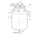
- FIG. 11 is a diagram illustrating the configuration of an accumulator 300B according to Embodiment 3 when viewed from the side of container 310;
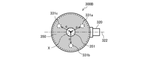
- FIG. 11 is a diagram illustrating the configuration of an accumulator 300B according to Embodiment 3 when viewed from the upper surface side of container 310;
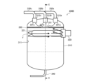
- FIG. 11 is a diagram illustrating the flow of refrigerant in container 310 in accumulator 300B according to Embodiment 3 when viewed from the side of container 310;
- FIG. 1 is a diagram showing the configuration of a refrigeration system 1 equipped with an accumulator 300 according to Embodiment 1.
- a refrigerating device 1 shown in FIG. 1 is a refrigerating cycle device that performs vapor compression refrigerating cycle operation.
- a refrigerating device 1 will be described as an example of a refrigerating cycle device.
- the refrigerating device 1 is, for example, a device that cools a room, a warehouse, or the like, which is a space to be cooled in a room, warehouse, showcase, refrigerator, or the like.
- a refrigerating apparatus 1 of Embodiment 1 has a heat source side unit 10 and a user side unit 20 . As shown in FIG. 1, the refrigerating apparatus 1 of Embodiment 1 has one heat source side unit 10 and one user side unit 20, but the number of these units is not limited. For example, the number of heat source side units 10 may be two or more. Alternatively, two or more user units 20 may be connected in parallel.
- the heat source side unit 10 and the user side unit 20 are connected by a liquid refrigerant extension pipe 600 and a gas refrigerant extension pipe 700 to form a refrigerant circuit for circulating the refrigerant.
- the refrigeration system 1 in which heat is exchanged between refrigerant and air will be described. However, it is not limited to this. For example, it may be a refrigeration system 1 in which fluid such as water, refrigerant, or brine exchanges heat with the refrigerant.
- the user unit 20 is, for example, a unit installed in a room that is a space to be cooled.
- the user-side unit 20 has a user-side expansion valve 400 and a user-side heat exchanger 500 that are part of the configuration of the refrigerant circuit.
- the user unit 20 also has a user fan 510 .
- the user-side expansion valve 400 is a decompression device that reduces the pressure of the refrigerant flowing through the refrigerant circuit and adjusts the flow rate.
- the user-side expansion valve 400 has, for example, a throttle device such as an electronic expansion valve or a temperature-sensitive expansion valve.
- a throttle device such as an electronic expansion valve or a temperature-sensitive expansion valve.
- the user-side expansion valve 400 is installed in the user-side unit 20 in the first embodiment, it may be installed in the heat source-side unit 10 .
- the user-side heat exchanger 500 is a heat exchanger that functions as an evaporator that evaporates the refrigerant through heat exchange with indoor air.
- the utilization side heat exchanger 500 is, for example, a fin-and-tube heat exchanger configured with a plurality of heat transfer tubes and a plurality of fins.
- the usage-side fan 510 is a blower that blows air to the usage-side heat exchanger 500 .
- the user-side fan 510 is arranged near the user-side heat exchanger 500 .
- User-side fan 510 is configured to include, for example, a centrifugal fan, a multi-blade fan, and the like.
- the user-side fan 510 may be a fan that can adjust the amount of air blown to the user-side heat exchanger 500 by controlling the rotation speed of the motor.
- the heat source side unit 10 in the refrigerating apparatus 1 of Embodiment 1 has a plurality of compressors 100a, 100b and 100c, a heat source side heat exchanger 200 and one accumulator 300.
- the heat source side unit 10 also has a heat source side fan 210, an oil regulator 110a, an oil regulator 110b, and an oil regulator 110c.
- the compressors 100a, 100b, and 100c compress the sucked refrigerant and discharge high-temperature and high-pressure refrigerant.
- the compressor 100a, the compressor 100b, and the compressor 100c compress the refrigerant sucked from the suction pipe 800a, the suction pipe 800b, and the suction pipe 800c (hereinafter simply referred to as the "suction pipe 800"), respectively, to a high temperature and a High pressure refrigerant is discharged.
- Each compressor 100 is connected to an accumulator 300 via a corresponding intake pipe 800 . As shown in FIG.
- the compressor 100 of Embodiment 1 will be described as a constant speed compressor. However, it is not limited to this.
- the compressor 100 may be an inverter compressor that can arbitrarily change the operating frequency to change the capacity (amount of refrigerant sent out per unit time).
- the heat source side heat exchanger 200 is a heat exchanger that functions as a condenser that condenses refrigerant through heat exchange with outdoor air.
- the heat source side heat exchanger 200 is, for example, a fin-and-tube heat exchanger configured with a plurality of heat transfer tubes and a plurality of fins.
- the heat source side heat exchanger 200 of Embodiment 1 is described as functioning as a condenser, it may have the function of a supercooler that supercools the refrigerant.
- the heat source side fan 210 is a blower that sends air to the heat source side heat exchanger 200 .
- the heat source side fan 210 is arranged near the heat source side heat exchanger 200 .
- Heat source side fan 210 is configured to include, for example, a centrifugal fan, a multi-blade fan, and the like.
- the heat source side fan 210 is driven by a motor (not shown).
- Oil regulator 110a, oil regulator 110b, and oil regulator 110c are installed between oil return pipe 340 of accumulator 300 and corresponding compressor 100, which will be described later. .
- Oil regulator 110 may control the amount of oil supplied back to each corresponding compressor 100 .
- Oil regulator 110 in Embodiment 1 is a container that stores oil discharged from oil return pipe 340 . However, it is not limited to this.
- the oil regulator 110 may be configured to have a valve or the like for controlling the amount of oil to be supplied. Also, the oil regulator 110 may not be installed.
- FIG. 2 is a diagram illustrating the configuration of the accumulator 300 according to Embodiment 1 when viewed from the side of the container 310.
- FIG. FIG. 3 is a diagram illustrating the configuration of accumulator 300 according to Embodiment 1 when viewed from the upper surface (upper bottom surface) side of container 310 .
- the accumulator 300 of Embodiment 1 stores surplus refrigerant in the refrigerant circuit.
- the accumulator 300 comprises a container 310 , an inlet line 320 , a plurality of outlet lines 330 a , 330 b and 330 c and an oil return line 340 .
- the members inside the container 310 are indicated by dotted lines.
- the container 310 is a closed cylindrical container that forms the main body of the accumulator 300 .
- the center axis X is defined as the central axis penetrating the container 310 in the height direction.
- the container 310 also has an inner peripheral surface 311 .
- the container 310 has a nozzle 312a, a nozzle 312b, and a nozzle 312c on its upper surface.
- the nozzles 312a, 312b, and 312c have through-holes that communicate the inside and outside of the container 310, and the openings in the container 310 extend along the central axis X from the upper surface of the container 310 to the lower surface (lower side). bottom).
- Outflow pipes 330a, 330b, and 330c of nozzles 312a, 312b, and 312c are connected by inserting through-holes of the outflow pipes 330a, 330b, and 330c, respectively.
- the nozzle stubs 312 are arranged at the same position in the height direction inside the container 310 .
- the inflow pipe 320 is a pipe through which the refrigerant flows into the container 310 from the utilization side heat exchanger 500 serving as an evaporator via the gas refrigerant extension pipe 700 .
- Refrigerant in which gas refrigerant, which is gaseous refrigerant, and liquid refrigerant, which is liquid refrigerant, are mixed (hereinafter referred to as gas-liquid mixed refrigerant) flows into inflow pipe 320 .
- the gas-liquid mixed refrigerant includes oil that serves as a lubricating oil for the compressor 100 .
- the inflow pipe 320 penetrates the side surface of the container 310 along the direction (horizontal direction) orthogonal to the central axis X of the container 310 and is inserted into the container 310 .
- the tip of the inflow pipe 320 inside the container 310 serves as an inflow port 321 .
- the inflow port 321 is an opening through which the gas-liquid mixed refrigerant flows into the container 310 .
- the inflow port 321 is positioned within the container 310 at a constant distance from the inner peripheral surface 311 of the container 310 .
- the inflow port 321 is located at a position where the gas-liquid mixed refrigerant can collide with the inner peripheral surface 311 of the container 310 and be swirled in the circumferential direction.
- the end surface of the inflow pipe 320 on the side of the inflow port 321 is an inclined surface that is inclined with respect to the pipe axis 322 of the inflow pipe 320 in order to increase the opening area.
- Outflow pipe 330a, outflow pipe 330b, and outflow pipe 330c are connected to suction pipe 800a, suction pipe 800b, and suction pipe 800c, respectively, and flow refrigerant from container 310. This is the outflow tube.
- the refrigerant in container 310 flows out from each outflow pipe 330 to the corresponding compressor 100 side and is sucked.
- Each outflow pipe 330 in Embodiment 1 is inserted into the container 310 until it does not penetrate the nozzle 312 of the container 310 described above.
- Each outflow pipe 330 is connected to the container 310 on the upper surface of the container 310, and the connecting portion is also located above the inflow pipe 320 in the height direction. Since each outflow pipe 330 does not pass through the nozzle 312 , it does not form a U-shaped pipe inside the container 310 .
- the outflow port 331 is an opening through which the gas refrigerant flows out from inside the container 310 .
- one end of the outflow pipe 330 on the inner side of the container 310 is inserted into the nozzle 312 and connected.
- the opening portion of the lower end (lower end) of the nozzle 312 located inside the container 310 serves as the outflow port 331 of the outflow pipe 330, and the height direction of each outflow port 331 is The position is the same as the lower end of the nozzle 312 and aligned in the height direction. Further, the positions of the outlets 331 are such that the distance a between the adjacent outlets 331 is equal on the circumference centered on the central axis X. As shown in FIG. Therefore, in each outlet 331, the distance between each outlet 331 and the central axis X is the same.
- the interval between adjacent outlets 331 is d.
- the interval d is set here, for example, to about 170 mm.
- the distance d is as small as possible and located near the central axis X in the vicinity of the central axis X if there are no circumstances. Better. Therefore, the distance d is determined to be the minimum based on manufacturing restrictions and the like.
- Each outflow port 331 is located above the inflow pipe 320 in the height direction.
- the oil return pipe 340 is a pipe connected to each compressor 100 via each oil regulator 110 .
- the oil that has flowed into the container 310 from the inflow pipe 320 and accumulated in the container 310 together with the gas-liquid mixed refrigerant is returned to each compressor 100 through the oil return pipe 340 . Therefore, the accumulator 300 in Embodiment 1 does not need to have a mechanism in which the outflow pipe 330 provided with the oil return hole is inserted to the bottom of the container 310 to return the oil through the outflow pipe 330 .
- FIG. 4 is a diagram illustrating the flow of refrigerant in container 310 in accumulator 300 according to Embodiment 1 when viewed from the top side of container 310 .
- FIG. 5 is a diagram illustrating the flow of refrigerant in container 310 in accumulator 300 according to Embodiment 1 when viewed from the side of container 310 .
- the flow of the coolant is indicated by streamlines Y and arrows.
- the gas-liquid mixed refrigerant that has flowed out of the user-side heat exchanger 500 of the refrigeration system 1 serving as an evaporator passes through the gas refrigerant extension pipe 700, passes through the inflow pipe 320, and flows into the container 310 from the inflow port 321. do.
- the inflow pipe 320 is provided so as to penetrate the container 310 in the direction orthogonal to the central axis X thereof, as described above.
- the gas-liquid mixed refrigerant that has flowed into the container 310 from the inlet 321 of the inflow pipe 320 collides with the inner peripheral surface 311 of the container 310 substantially perpendicularly.
- the gas-liquid mixed refrigerant that has collided with the inner peripheral surface 311 of the container 310 flows along the inner peripheral surface 311 of the container 310 in two directions in the circumferential direction.
- the refrigerant flowing in the circumferential direction along the inner peripheral surface 311 of the container 310 has not only a circumferential flow but also a downward flow.
- the liquid refrigerant flows toward the bottom of container 310 due to its own weight.
- Liquid refrigerant droplets and oil droplets contained in the gas-liquid mixed refrigerant scatter in a mist form due to collision or the like, drip along the inner peripheral surface 311 of the container 310 , and accumulate in the lower portion of the container 310 .
- the droplets of the liquid refrigerant and the droplets of the oil do not drip, and the scattered droplets may flow out from the outlet 331 through the outflow pipe 330 as they are.
- the gas-liquid mixed refrigerant that has collided with the inner peripheral surface 311 of the container 310 to flow in such a trajectory, the gas-liquid mixed refrigerant that has flowed into the container 310 from the inlet 321 must be It is important that the inlet pipe 320 is arranged so that it impinges on 311 almost straight.
- the distance between the inlet 321 of the inflow pipe 320 and the inner peripheral surface 311 is short (the distance between the inner peripheral surface 311 and the inlet 321 ⁇ the distance between the inner peripheral surface 311 and the central axis X ) is important.
- the stored liquid refrigerant may be influenced by the flow of the gas-liquid mixed refrigerant flowing into the container 310 through the inflow pipe 320, depending on conditions such as the inflow speed. , the liquid surface rolls up. A portion of the liquid refrigerant that has swirled up passes through each outflow port 331 and flows out from each outflow pipe 330 . Furthermore, a portion of the liquid refrigerant that has swirled up is horizontally pushed out in the same direction as the refrigerant flowing along the inner peripheral surface 311 .
- the liquid refrigerant split into two directions together with the gas-liquid mixed refrigerant collides at an insertion portion (hereinafter referred to as a collision point A) where the inflow pipe 320 is inserted into the container 310 and connected.
- a collision point A an insertion portion where the inflow pipe 320 is inserted into the container 310 and connected.
- the liquid refrigerant After colliding with the collision point A, the liquid refrigerant further advances in the direction toward the central axis X from the inner peripheral surface 311, and then flows out from the outlet 331 existing in the traveling direction.
- the liquid refrigerant in the container 310 when the liquid refrigerant in the container 310 is almost full and reaches the height of the outlet 331 , the liquid refrigerant flows out from the outlet 331 .
- the outflow port 331 is positioned at the lower end of the nozzle 312 with the same height and does not penetrate through the pipe. There is no Therefore, the outflow pipes 330 do not vary in position in the height direction due to manufacturing variations such as the length of the outflow pipes 330, pipe processing, and pipe connection. Therefore, the accumulator 300 of Embodiment 1 can suppress variation in the amount of refrigerant flowing out from each outflow pipe 330 .
- each outflow port 331 opens along the central axis X from the upper surface to the lower surface of the container 310 in the same manner as the nozzle 312 . Therefore, each of the outlets 331 faces the same direction, and variation in the amount of refrigerant that flows out due to differences in the orientation of the outlets 331 can be suppressed. Furthermore, in each outlet 331, the interval d between the outlets 331 adjacent to each other is made as small as possible. Therefore, the positions of the outlets 331 are close to each other, and variations in the outflow amount of the refrigerant due to differences in the positions of the outlets 331 can be suppressed.
- the inflow pipe 320 is configured to pass through the container 310 in the direction orthogonal to the central axis X thereof.
- Each outflow pipe 330 has an outflow port 331, which is an opening in the container 310, located at the lower end of the nozzle 312, and is arranged at equal intervals on the circumference around the central axis X. Therefore, the accumulator 300 does not cause variation in the height position of the plurality of outflow pipes 330 due to manufacturing variations in pipe length, pipe processing, pipe connection, etc., and can suppress variation in the height position of the outflow port. .
- the accumulator 300 can reduce the difference in orientation and position of the outflow port 331 in each of the plurality of outflow pipes 330 . Therefore, the accumulator 300 of Embodiment 1 can suppress variation in the amount of refrigerant flowing out from each outflow pipe 330, and can improve performance.
- FIG. 6 is a diagram illustrating the configuration of accumulator 300A according to the second embodiment.
- FIG. 6 is a view of the container 310 viewed from the top side.
- the members inside the container 310 are indicated by dotted lines.
- the components denoted by the same reference numerals as in FIG. 2, etc. have the same functions as in the first embodiment.
- Accumulator 300A of the second embodiment differs from accumulator 300 of the first embodiment in the position of outflow port 331 of outflow pipe 330 and nozzle 312 of vessel 310 .
- the accumulator 300A of Embodiment 2 has a configuration in which the nozzles 312 are arranged on a circumference centered on the central axis X within the area C surrounded by the dotted line in FIG.
- a region C is a region surrounded by a semicircle with a radius b from the central axis X.
- FIG. Area C is the area on the side opposite to the side where the inflow pipe 320 is inserted into the container 310 and does not include the collision point A.
- a diameter b of the semicircle is perpendicular to the pipe axis 322 of the inflow pipe 320 in the horizontal direction.
- FIG. 7 is a diagram illustrating the flow of refrigerant in container 310 in accumulator 300A according to Embodiment 2 when viewed from the top side of container 310.
- FIG. 7 the flow of the coolant is indicated by the arrow of the streamline Y.
- FIG. Since the general flow of the gas-liquid mixed refrigerant in the container 310 is the same as in the accumulator 300 of the first embodiment, here the effect of the position of the outflow port 331 (nozzle 312) in the second embodiment will be mainly described. explain.
- a nozzle 312 is installed in the area C.
- the region C is a region on the opposite side of the collision point A, which is the connecting portion between the container 310 and the inflow pipe 320, and is far from the collision point A.
- the liquid level of the stored liquid refrigerant is swirled up by the gas-liquid mixed refrigerant flowing into the container 310 through the inflow pipe 320 .
- a portion of the liquid refrigerant that has swirled up is horizontally pushed out in the same direction as the refrigerant flowing along the inner peripheral surface 311 .
- the liquid refrigerant collides with the inflow pipe 320 at the collision point A and further advances toward the central axis X from the inner peripheral surface 311 . Therefore, when the outflow port 331 is positioned near the pipe of the inflow pipe 320 or in the vicinity of the collision point A, the liquid refrigerant tends to flow out.
- the accumulator 300A of Embodiment 2 is configured such that the nozzle 312 is installed in the region C and the outflow port 331 of each outflow pipe 330 is positioned. Therefore, the liquid refrigerant that has been lifted up slows down and falls downward due to gravity. Some outlets 331 are difficult to reach. Therefore, accumulator 300A of the second embodiment can suppress the amount of refrigerant flowing out of outflow pipes 330, and can further suppress variation in the amount of refrigerant flowing out of each outflow pipe 330.
- the same effect as the accumulator 300 of the first embodiment can be obtained. Furthermore, in the accumulator 300A of the second embodiment, the outflow port 331 of each outflow pipe 330 is positioned opposite to the side where the inflow pipe 320 is inserted into the container 310, and the position of the outflow port 331 is the liquid refrigerant. is far from the collision point A. Therefore, the accumulator 300 ⁇ /b>A of the second embodiment can suppress the outflow amount of liquid refrigerant itself, and can suppress variation in the amount of refrigerant flowing out from each outflow pipe 330 . Therefore, the accumulator 300A can improve performance.
- FIG. 8 is a diagram illustrating the configuration of an accumulator 300B according to Embodiment 3 when viewed from the side of container 310.
- FIG. 9 is a diagram illustrating the configuration of an accumulator 300B according to Embodiment 3 when viewed from the top side of container 310.
- the members inside the container 310 are indicated by dotted lines.
- the accumulator 300B of the third embodiment has a baffle plate 350 between the inflow pipe 320 and the outflow port 331 (nozzle stub 312) of the outflow pipe 330.
- the baffle plate 350 serves as a baffle plate having a rectifying action.
- the baffle plate 350 of Embodiment 3 has one or more openings 351 and is installed horizontally between the inflow pipe 320 and the outflow port 331 .
- the shape of baffle plate 350 is, for example, a disc shape.
- baffle plate 350 has one opening 351 .
- the distance c between the opening 351 and each outlet 331 is uniform.
- the baffle plate 350 and the opening 351 have circular shapes, but the shapes are not limited to this.
- FIG. 10 is a diagram illustrating the flow of refrigerant in container 310 in accumulator 300B according to Embodiment 3 when viewed from the side of container 310.
- FIG. 10 the refrigerant flow in the accumulator 300B of Embodiment 3 will be described with reference to FIG. Since the general flow of the gas-liquid mixed refrigerant in container 310 is similar to that of accumulator 300 of the first embodiment, the action of baffle plate 350 of the third embodiment will be mainly described here.
- the gas-liquid mixed refrigerant flowing into the container 310 from the inlet 321 and the liquid refrigerant stored in the container 310 flow out from the outlet 331 .
- One is a pattern in which the droplets contained in the gas-liquid mixed refrigerant that has flowed in do not drip, but pass through the outflow pipe 330 from the outflow port 331 and flow out as they are.
- the other pattern is a pattern in which the stored liquid refrigerant is drawn up by the gas-liquid mixed refrigerant that has flowed in and flows out through the outflow pipe 330 from the outflow port 331 .
- the liquid refrigerant collides with the baffle plate 350 installed between the inflow pipe 320 and the outflow port 331 of the outflow pipe 330, and the baffle plate 350 blocks the liquid refrigerant. Therefore, the accumulator 300 ⁇ /b>B of the third embodiment can suppress the amount of liquid refrigerant flowing out from the outflow pipe 330 . Further, by making the distance c between the opening 351 of the baffle plate 350 and each outlet 331 uniform, the refrigerant passing through the opening 351 reaches each outlet 331 uniformly.
- accumulator 300B of the third embodiment As described above, according to the accumulator 300B of the third embodiment, the same effects as those of the first embodiment can be obtained. Furthermore, accumulator 300B of Embodiment 3 has baffle plate 350 installed between inflow pipe 320 and outflow port 331 . Therefore, the accumulator 300B of Embodiment 3 can suppress the outflow amount of liquid refrigerant itself, and can suppress variations in the amount of refrigerant flowing out from each outflow pipe 330, thereby improving the performance. be able to.
- the baffle plate 350 is arranged close to the outflow port 331 (outflow pipe 330), and the distance between the baffle plate 350 and the inflow pipe 320 > the distance between the baffle plate 350 and the outflow port 331 (outflow pipe 330) distance.
- the accumulator 300B can obtain a stable effect.
- the baffle plate 350 is located near the inflow pipe 320. Therefore, the baffle plate 350 can be arranged in the cylindrical portion of the container 310 in the same manner as the inflow pipe 320, and the arrangement of the baffle plate 350 is facilitated.
- Embodiment 4 In the accumulators 300 to 300B according to Embodiments 1 to 3 described above, the end surface of the inflow pipe 320 on the side of the inflow port 321 is inclined as described above. Depending on the direction of the inclined surface, the amount of the gas-liquid mixed refrigerant that flows along the inner peripheral surface 311 of the container 310 in two directions in the circumferential direction may differ. For example, the amount of coolant increases on the side of the inclined surface facing the inner peripheral surface 311 with a larger area. Therefore, by determining the position of the outflow port 331 in each outflow pipe 330 based on the direction of the inclined surface of the inflow port 321, it is possible to suppress variation in the amount of refrigerant flowing out from each outflow pipe 330. FIG.
- the accumulator 300A and the like according to Embodiment 2 described above suppress variation in the amount of refrigerant flowing out from each outflow pipe 330 by adjusting the position of each outflow port 331 . That is, although the accumulator 300A reduces the variation in the amount of refrigerant, even if there is variation in the amount of refrigerant flowing out of each outflow pipe 330 of the accumulator 300, equipment such as a compressor connected to each outflow pipe 330 It suffices that the variation in the amount of refrigerant is suppressed at the time when the refrigerant is taken in.
- suction pipe 800 connected to outflow pipe 330 through which a large amount of refrigerant passes has a longer pipe length to compressor 100 than other suction pipes 800 to increase pressure loss. Besides the length, the pressure loss in the suction pipe 800 may be increased by increasing the number of bent portions.
- the refrigeration system 1 has been described as an example of the refrigeration cycle system, but the invention is not limited to this.
- it can also be applied to other refrigeration cycle devices such as air conditioners.
- 1 refrigeration device 10 heat source side unit, 20 user side unit, 100, 100a, 100b, 100c compressor, 110, 110a, 110b, 110c oil regulator, 200 heat source side heat exchanger, 210 heat source side fan, 300, 300A, 300B accumulator, 310 container, 311 inner peripheral surface, 312, 312a, 312b, 312c nozzle, 320 inflow pipe, 321 inflow port, 322 pipe shaft, 330, 330a, 330b, 330c outflow pipe, 331, 331a, 331b, 331c Outlet, 340 Oil return pipe, 350 Baffle plate, 351 Opening, 400 User side expansion valve, 500 User side heat exchanger, 510 User side fan, 600 Liquid refrigerant extension pipe, 700 Gas refrigerant extension pipe, 800, 800a, 800b, 800c Suction piping.
Landscapes
- Engineering & Computer Science (AREA)
- Chemical & Material Sciences (AREA)
- Analytical Chemistry (AREA)
- Power Engineering (AREA)
- Physics & Mathematics (AREA)
- Mechanical Engineering (AREA)
- Thermal Sciences (AREA)
- General Engineering & Computer Science (AREA)
- Compressor (AREA)
Priority Applications (3)
| Application Number | Priority Date | Filing Date | Title |
|---|---|---|---|
| JP2023559377A JP7646020B2 (ja) | 2021-11-15 | 2021-11-15 | アキュムレータおよび冷凍サイクル装置 |
| CN202180102511.2A CN118159792A (zh) | 2021-11-15 | 2021-11-15 | 储能器以及制冷循环装置 |
| PCT/JP2021/041905 WO2023084771A1 (ja) | 2021-11-15 | 2021-11-15 | アキュムレータおよび冷凍サイクル装置 |
Applications Claiming Priority (1)
| Application Number | Priority Date | Filing Date | Title |
|---|---|---|---|
| PCT/JP2021/041905 WO2023084771A1 (ja) | 2021-11-15 | 2021-11-15 | アキュムレータおよび冷凍サイクル装置 |
Publications (1)
| Publication Number | Publication Date |
|---|---|
| WO2023084771A1 true WO2023084771A1 (ja) | 2023-05-19 |
Family
ID=86335464
Family Applications (1)
| Application Number | Title | Priority Date | Filing Date |
|---|---|---|---|
| PCT/JP2021/041905 Ceased WO2023084771A1 (ja) | 2021-11-15 | 2021-11-15 | アキュムレータおよび冷凍サイクル装置 |
Country Status (3)
| Country | Link |
|---|---|
| JP (1) | JP7646020B2 (https=) |
| CN (1) | CN118159792A (https=) |
| WO (1) | WO2023084771A1 (https=) |
Citations (4)
| Publication number | Priority date | Publication date | Assignee | Title |
|---|---|---|---|---|
| JP2013217623A (ja) * | 2012-04-12 | 2013-10-24 | Mitsubishi Electric Corp | アキュムレータ及び冷凍サイクル装置 |
| WO2015129047A1 (ja) * | 2014-02-28 | 2015-09-03 | 三菱電機株式会社 | アキュムレータ及びこのアキュムレータを備えた冷凍装置 |
| JP2017020768A (ja) * | 2015-07-14 | 2017-01-26 | 東芝キヤリア株式会社 | 遠心分離式オイルセパレータ及びこれを用いた冷凍サイクル装置 |
| WO2021186549A1 (ja) * | 2020-03-17 | 2021-09-23 | 三菱電機株式会社 | 冷凍空調装置 |
Family Cites Families (3)
| Publication number | Priority date | Publication date | Assignee | Title |
|---|---|---|---|---|
| JP2005134009A (ja) | 2003-10-29 | 2005-05-26 | Mitsubishi Electric Corp | 冷媒分配器 |
| JP5193631B2 (ja) | 2008-03-06 | 2013-05-08 | パナソニック株式会社 | 冷媒分流器及び冷媒分流器を備えた熱交換器 |
| JP6670196B2 (ja) | 2016-07-25 | 2020-03-18 | 荏原冷熱システム株式会社 | 圧縮式冷凍機の気液分離器 |
-
2021
- 2021-11-15 JP JP2023559377A patent/JP7646020B2/ja active Active
- 2021-11-15 WO PCT/JP2021/041905 patent/WO2023084771A1/ja not_active Ceased
- 2021-11-15 CN CN202180102511.2A patent/CN118159792A/zh active Pending
Patent Citations (4)
| Publication number | Priority date | Publication date | Assignee | Title |
|---|---|---|---|---|
| JP2013217623A (ja) * | 2012-04-12 | 2013-10-24 | Mitsubishi Electric Corp | アキュムレータ及び冷凍サイクル装置 |
| WO2015129047A1 (ja) * | 2014-02-28 | 2015-09-03 | 三菱電機株式会社 | アキュムレータ及びこのアキュムレータを備えた冷凍装置 |
| JP2017020768A (ja) * | 2015-07-14 | 2017-01-26 | 東芝キヤリア株式会社 | 遠心分離式オイルセパレータ及びこれを用いた冷凍サイクル装置 |
| WO2021186549A1 (ja) * | 2020-03-17 | 2021-09-23 | 三菱電機株式会社 | 冷凍空調装置 |
Also Published As
| Publication number | Publication date |
|---|---|
| JPWO2023084771A1 (https=) | 2023-05-19 |
| JP7646020B2 (ja) | 2025-03-14 |
| CN118159792A (zh) | 2024-06-07 |
Similar Documents
| Publication | Publication Date | Title |
|---|---|---|
| US11940162B2 (en) | Integrated air conditioner | |
| US11365912B2 (en) | Suction duct and multiple suction ducts inside a shell of a flooded evaporator | |
| JP6352401B2 (ja) | 空気調和装置 | |
| US7832231B2 (en) | Multichannel evaporator with flow separating manifold | |
| JP6466047B1 (ja) | 熱交換器及び空気調和装置 | |
| CN107270590A (zh) | 蒸发器及具有该蒸发器的制冷系统 | |
| JP2019522165A (ja) | 部屋の天井の下に設置するための冷却装置 | |
| JP7646020B2 (ja) | アキュムレータおよび冷凍サイクル装置 | |
| JPH11118199A (ja) | 空気調和機 | |
| US20200309407A1 (en) | Heat exchange unit and air-conditioning apparatus including the same | |
| KR102046634B1 (ko) | 공기조화기의 분배기 | |
| CN213841119U (zh) | 一种空调室内机 | |
| WO2020183606A1 (ja) | 空気調和機 | |
| KR20150045752A (ko) | 열교환기 및 이를 갖는 공기조화기 | |
| US11561025B2 (en) | Air-conditioning apparatus | |
| KR20220001742U (ko) | 외기조화기의 동파 방지용 수직형 코일 | |
| KR20150098141A (ko) | 열교환기 및 이를 갖는 공기조화기 | |
| WO2020245982A1 (ja) | 熱交換器及び冷凍サイクル装置 | |
| CN220506932U (zh) | 空调室内机 | |
| CN223036509U (zh) | 一种文丘里管冷梁 | |
| CN219454089U (zh) | 一种空调室内机 | |
| CN217402692U (zh) | 分流器、换热器组件及空调 | |
| WO2024209545A1 (ja) | 冷凍サイクル装置 | |
| WO2023199426A1 (ja) | 冷凍サイクル装置 | |
| KR102046633B1 (ko) | 공기조화기의 분배기 |
Legal Events
| Date | Code | Title | Description |
|---|---|---|---|
| 121 | Ep: the epo has been informed by wipo that ep was designated in this application |
Ref document number: 21964124 Country of ref document: EP Kind code of ref document: A1 |
|
| WWE | Wipo information: entry into national phase |
Ref document number: 2023559377 Country of ref document: JP |
|
| WWE | Wipo information: entry into national phase |
Ref document number: 202180102511.2 Country of ref document: CN |
|
| 122 | Ep: pct application non-entry in european phase |
Ref document number: 21964124 Country of ref document: EP Kind code of ref document: A1 |