WO2023084771A1 - Accumulator and refrigeration cycle device - Google Patents
Accumulator and refrigeration cycle device Download PDFInfo
- Publication number
- WO2023084771A1 WO2023084771A1 PCT/JP2021/041905 JP2021041905W WO2023084771A1 WO 2023084771 A1 WO2023084771 A1 WO 2023084771A1 JP 2021041905 W JP2021041905 W JP 2021041905W WO 2023084771 A1 WO2023084771 A1 WO 2023084771A1
- Authority
- WO
- WIPO (PCT)
- Prior art keywords
- container
- outflow
- refrigerant
- accumulator
- pipe
- Prior art date
Links
- 238000005057 refrigeration Methods 0.000 title claims description 18
- 239000003507 refrigerant Substances 0.000 claims abstract description 142
- 239000007788 liquid Substances 0.000 claims description 66
- 239000003921 oil Substances 0.000 description 29
- 238000010586 diagram Methods 0.000 description 20
- 230000002093 peripheral effect Effects 0.000 description 20
- 230000000694 effects Effects 0.000 description 4
- 238000004519 manufacturing process Methods 0.000 description 4
- 239000002826 coolant Substances 0.000 description 3
- 239000012530 fluid Substances 0.000 description 2
- 239000012267 brine Substances 0.000 description 1
- 230000006835 compression Effects 0.000 description 1
- 238000007906 compression Methods 0.000 description 1
- 239000000470 constituent Substances 0.000 description 1
- 230000006837 decompression Effects 0.000 description 1
- 230000005484 gravity Effects 0.000 description 1
- 238000003780 insertion Methods 0.000 description 1
- 230000037431 insertion Effects 0.000 description 1
- 239000010687 lubricating oil Substances 0.000 description 1
- 239000003595 mist Substances 0.000 description 1
- 230000000149 penetrating effect Effects 0.000 description 1
- HPALAKNZSZLMCH-UHFFFAOYSA-M sodium;chloride;hydrate Chemical compound O.[Na+].[Cl-] HPALAKNZSZLMCH-UHFFFAOYSA-M 0.000 description 1
- XLYOFNOQVPJJNP-UHFFFAOYSA-N water Substances O XLYOFNOQVPJJNP-UHFFFAOYSA-N 0.000 description 1
Images


Classifications
-
- F—MECHANICAL ENGINEERING; LIGHTING; HEATING; WEAPONS; BLASTING
- F25—REFRIGERATION OR COOLING; COMBINED HEATING AND REFRIGERATION SYSTEMS; HEAT PUMP SYSTEMS; MANUFACTURE OR STORAGE OF ICE; LIQUEFACTION SOLIDIFICATION OF GASES
- F25B—REFRIGERATION MACHINES, PLANTS OR SYSTEMS; COMBINED HEATING AND REFRIGERATION SYSTEMS; HEAT PUMP SYSTEMS
- F25B43/00—Arrangements for separating or purifying gases or liquids; Arrangements for vaporising the residuum of liquid refrigerant, e.g. by heat
Definitions
- This technology relates to accumulators and refrigeration cycle equipment.
- it relates to an accumulator that can be piped to a plurality of compressors.
- an accumulator or the like is generally installed as a pressure vessel between the evaporator of the refrigerant circuit and the refrigerant suction side of the compressor to store excess refrigerant during operation. are doing.
- an outdoor unit having a plurality of compressors there is a single accumulator (see Patent Literature 1, for example).
- Such an accumulator has one inflow pipe and multiple outflow pipes connected to the suction sides of multiple compressors.
- a gas-liquid mixed refrigerant in which refrigerant and oil are mixed flows into the inflow pipe.
- the inflow pipe is provided so as to penetrate perpendicularly to the central axis of the cylindrical container.
- the outflow pipe is connected to the suction sides of the plurality of compressors, and has one end located inside the container and serving as an outflow port through which the gas refrigerant in the container flows out toward the plurality of compressors.
- a plurality of outflow ports are centrally arranged in the central portion of the container by means of piping.
- the gas-liquid mixed refrigerant flowing into the main body container collides with the liquid surface of the liquid refrigerant stored in the container, causing the liquid surface to become turbulent. For this reason, the liquid refrigerant that has been lifted up flows out through the outflow pipes from the respective outflow ports.
- the gas-liquid mixed refrigerant that has flowed in collides with the wall serving as the inner peripheral surface of the container, and then directly flows out through the outflow pipes from each outflow port.
- the accumulator described in Patent Document 1 has a configuration in which each outflow port is brought to the center by a U-shaped pipe to suppress variations in the outflow amount.
- outflow pipes including U-shaped pipes, may have different outlet heights due to manufacturing variations.
- the refrigerant flows out more easily from the outflow port located at a lower position close to the liquid surface. Therefore, the accumulator will have a biased outflow due to the difference in the height of the outlet.
- the outlets face different directions, there is a problem that the amount of outflow is uneven depending on the behavior of the fluid in the container.
- an object of the present invention to provide an accumulator and a refrigeration cycle apparatus including the accumulator that improves the variation in the amount of refrigerant flowing out from a plurality of outflow pipes.
- the disclosed accumulator includes a cylindrical container, and an inflow pipe that is inserted through the side surface of the container in a direction orthogonal to the central axis of the container and through which the refrigerant that has passed through the pipe flows into the container.
- a plurality of outflow pipes through which the gaseous refrigerant that has passed through the pipes flows out from the container, one end of the plurality of outflow pipes is located inside the container, one end has an outflow port, and each outflow The outflow ports of the pipes are located above the inflow pipes in the height direction, and the directions in which the outflow ports of the respective outflow pipes open are the same.
- the disclosed refrigeration cycle device has a refrigerant circuit in which a plurality of compressors, condensers, expansion valves, and evaporators are connected by piping, and the accumulator is disposed between the evaporator and the plurality of compressors. to be connected.
- the outflow port of the outflow pipe is located above the inflow pipe in the height direction, and the direction in which the outflow port of each outflow pipe opens is the same, so that from the plurality of outflow pipes Variation in the outflow amount of each outflowing refrigerant can be improved.
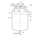
- FIG. 1 is a diagram showing the configuration of a refrigeration system 1 equipped with an accumulator 300 according to Embodiment 1.
- FIG. 4 is a diagram illustrating the configuration of accumulator 300 according to Embodiment 1 when viewed from the side of container 310.
- FIG. 4 is a diagram illustrating the configuration of accumulator 300 according to Embodiment 1 when viewed from the upper surface side of container 310.
- FIG. 3 is a diagram illustrating the flow of refrigerant in container 310 in accumulator 300 according to Embodiment 1 when viewed from the top side of container 310.
- FIG. 3 is a diagram illustrating the flow of refrigerant in container 310 in accumulator 300 according to Embodiment 1 when viewed from the side of container 310.
- FIG. 10 is a diagram illustrating the configuration of an accumulator 300A according to Embodiment 2;
- FIG. FIG. 11 is a diagram illustrating the flow of refrigerant in container 310 in accumulator 300A according to Embodiment 2 when viewed from the top side of container 310;
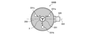
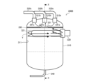
- FIG. 11 is a diagram illustrating the configuration of an accumulator 300B according to Embodiment 3 when viewed from the side of container 310;
- FIG. 11 is a diagram illustrating the configuration of an accumulator 300B according to Embodiment 3 when viewed from the upper surface side of container 310;
- FIG. 11 is a diagram illustrating the flow of refrigerant in container 310 in accumulator 300B according to Embodiment 3 when viewed from the side of container 310;
- FIG. 1 is a diagram showing the configuration of a refrigeration system 1 equipped with an accumulator 300 according to Embodiment 1.
- a refrigerating device 1 shown in FIG. 1 is a refrigerating cycle device that performs vapor compression refrigerating cycle operation.
- a refrigerating device 1 will be described as an example of a refrigerating cycle device.
- the refrigerating device 1 is, for example, a device that cools a room, a warehouse, or the like, which is a space to be cooled in a room, warehouse, showcase, refrigerator, or the like.
- a refrigerating apparatus 1 of Embodiment 1 has a heat source side unit 10 and a user side unit 20 . As shown in FIG. 1, the refrigerating apparatus 1 of Embodiment 1 has one heat source side unit 10 and one user side unit 20, but the number of these units is not limited. For example, the number of heat source side units 10 may be two or more. Alternatively, two or more user units 20 may be connected in parallel.
- the heat source side unit 10 and the user side unit 20 are connected by a liquid refrigerant extension pipe 600 and a gas refrigerant extension pipe 700 to form a refrigerant circuit for circulating the refrigerant.
- the refrigeration system 1 in which heat is exchanged between refrigerant and air will be described. However, it is not limited to this. For example, it may be a refrigeration system 1 in which fluid such as water, refrigerant, or brine exchanges heat with the refrigerant.
- the user unit 20 is, for example, a unit installed in a room that is a space to be cooled.
- the user-side unit 20 has a user-side expansion valve 400 and a user-side heat exchanger 500 that are part of the configuration of the refrigerant circuit.
- the user unit 20 also has a user fan 510 .
- the user-side expansion valve 400 is a decompression device that reduces the pressure of the refrigerant flowing through the refrigerant circuit and adjusts the flow rate.
- the user-side expansion valve 400 has, for example, a throttle device such as an electronic expansion valve or a temperature-sensitive expansion valve.
- a throttle device such as an electronic expansion valve or a temperature-sensitive expansion valve.
- the user-side expansion valve 400 is installed in the user-side unit 20 in the first embodiment, it may be installed in the heat source-side unit 10 .
- the user-side heat exchanger 500 is a heat exchanger that functions as an evaporator that evaporates the refrigerant through heat exchange with indoor air.
- the utilization side heat exchanger 500 is, for example, a fin-and-tube heat exchanger configured with a plurality of heat transfer tubes and a plurality of fins.
- the usage-side fan 510 is a blower that blows air to the usage-side heat exchanger 500 .
- the user-side fan 510 is arranged near the user-side heat exchanger 500 .
- User-side fan 510 is configured to include, for example, a centrifugal fan, a multi-blade fan, and the like.
- the user-side fan 510 may be a fan that can adjust the amount of air blown to the user-side heat exchanger 500 by controlling the rotation speed of the motor.
- the heat source side unit 10 in the refrigerating apparatus 1 of Embodiment 1 has a plurality of compressors 100a, 100b and 100c, a heat source side heat exchanger 200 and one accumulator 300.
- the heat source side unit 10 also has a heat source side fan 210, an oil regulator 110a, an oil regulator 110b, and an oil regulator 110c.
- the compressors 100a, 100b, and 100c compress the sucked refrigerant and discharge high-temperature and high-pressure refrigerant.
- the compressor 100a, the compressor 100b, and the compressor 100c compress the refrigerant sucked from the suction pipe 800a, the suction pipe 800b, and the suction pipe 800c (hereinafter simply referred to as the "suction pipe 800"), respectively, to a high temperature and a High pressure refrigerant is discharged.
- Each compressor 100 is connected to an accumulator 300 via a corresponding intake pipe 800 . As shown in FIG.
- the compressor 100 of Embodiment 1 will be described as a constant speed compressor. However, it is not limited to this.
- the compressor 100 may be an inverter compressor that can arbitrarily change the operating frequency to change the capacity (amount of refrigerant sent out per unit time).
- the heat source side heat exchanger 200 is a heat exchanger that functions as a condenser that condenses refrigerant through heat exchange with outdoor air.
- the heat source side heat exchanger 200 is, for example, a fin-and-tube heat exchanger configured with a plurality of heat transfer tubes and a plurality of fins.
- the heat source side heat exchanger 200 of Embodiment 1 is described as functioning as a condenser, it may have the function of a supercooler that supercools the refrigerant.
- the heat source side fan 210 is a blower that sends air to the heat source side heat exchanger 200 .
- the heat source side fan 210 is arranged near the heat source side heat exchanger 200 .
- Heat source side fan 210 is configured to include, for example, a centrifugal fan, a multi-blade fan, and the like.
- the heat source side fan 210 is driven by a motor (not shown).
- Oil regulator 110a, oil regulator 110b, and oil regulator 110c are installed between oil return pipe 340 of accumulator 300 and corresponding compressor 100, which will be described later. .
- Oil regulator 110 may control the amount of oil supplied back to each corresponding compressor 100 .
- Oil regulator 110 in Embodiment 1 is a container that stores oil discharged from oil return pipe 340 . However, it is not limited to this.
- the oil regulator 110 may be configured to have a valve or the like for controlling the amount of oil to be supplied. Also, the oil regulator 110 may not be installed.
- FIG. 2 is a diagram illustrating the configuration of the accumulator 300 according to Embodiment 1 when viewed from the side of the container 310.
- FIG. FIG. 3 is a diagram illustrating the configuration of accumulator 300 according to Embodiment 1 when viewed from the upper surface (upper bottom surface) side of container 310 .
- the accumulator 300 of Embodiment 1 stores surplus refrigerant in the refrigerant circuit.
- the accumulator 300 comprises a container 310 , an inlet line 320 , a plurality of outlet lines 330 a , 330 b and 330 c and an oil return line 340 .
- the members inside the container 310 are indicated by dotted lines.
- the container 310 is a closed cylindrical container that forms the main body of the accumulator 300 .
- the center axis X is defined as the central axis penetrating the container 310 in the height direction.
- the container 310 also has an inner peripheral surface 311 .
- the container 310 has a nozzle 312a, a nozzle 312b, and a nozzle 312c on its upper surface.
- the nozzles 312a, 312b, and 312c have through-holes that communicate the inside and outside of the container 310, and the openings in the container 310 extend along the central axis X from the upper surface of the container 310 to the lower surface (lower side). bottom).
- Outflow pipes 330a, 330b, and 330c of nozzles 312a, 312b, and 312c are connected by inserting through-holes of the outflow pipes 330a, 330b, and 330c, respectively.
- the nozzle stubs 312 are arranged at the same position in the height direction inside the container 310 .
- the inflow pipe 320 is a pipe through which the refrigerant flows into the container 310 from the utilization side heat exchanger 500 serving as an evaporator via the gas refrigerant extension pipe 700 .
- Refrigerant in which gas refrigerant, which is gaseous refrigerant, and liquid refrigerant, which is liquid refrigerant, are mixed (hereinafter referred to as gas-liquid mixed refrigerant) flows into inflow pipe 320 .
- the gas-liquid mixed refrigerant includes oil that serves as a lubricating oil for the compressor 100 .
- the inflow pipe 320 penetrates the side surface of the container 310 along the direction (horizontal direction) orthogonal to the central axis X of the container 310 and is inserted into the container 310 .
- the tip of the inflow pipe 320 inside the container 310 serves as an inflow port 321 .
- the inflow port 321 is an opening through which the gas-liquid mixed refrigerant flows into the container 310 .
- the inflow port 321 is positioned within the container 310 at a constant distance from the inner peripheral surface 311 of the container 310 .
- the inflow port 321 is located at a position where the gas-liquid mixed refrigerant can collide with the inner peripheral surface 311 of the container 310 and be swirled in the circumferential direction.
- the end surface of the inflow pipe 320 on the side of the inflow port 321 is an inclined surface that is inclined with respect to the pipe axis 322 of the inflow pipe 320 in order to increase the opening area.
- Outflow pipe 330a, outflow pipe 330b, and outflow pipe 330c are connected to suction pipe 800a, suction pipe 800b, and suction pipe 800c, respectively, and flow refrigerant from container 310. This is the outflow tube.
- the refrigerant in container 310 flows out from each outflow pipe 330 to the corresponding compressor 100 side and is sucked.
- Each outflow pipe 330 in Embodiment 1 is inserted into the container 310 until it does not penetrate the nozzle 312 of the container 310 described above.
- Each outflow pipe 330 is connected to the container 310 on the upper surface of the container 310, and the connecting portion is also located above the inflow pipe 320 in the height direction. Since each outflow pipe 330 does not pass through the nozzle 312 , it does not form a U-shaped pipe inside the container 310 .
- the outflow port 331 is an opening through which the gas refrigerant flows out from inside the container 310 .
- one end of the outflow pipe 330 on the inner side of the container 310 is inserted into the nozzle 312 and connected.
- the opening portion of the lower end (lower end) of the nozzle 312 located inside the container 310 serves as the outflow port 331 of the outflow pipe 330, and the height direction of each outflow port 331 is The position is the same as the lower end of the nozzle 312 and aligned in the height direction. Further, the positions of the outlets 331 are such that the distance a between the adjacent outlets 331 is equal on the circumference centered on the central axis X. As shown in FIG. Therefore, in each outlet 331, the distance between each outlet 331 and the central axis X is the same.
- the interval between adjacent outlets 331 is d.
- the interval d is set here, for example, to about 170 mm.
- the distance d is as small as possible and located near the central axis X in the vicinity of the central axis X if there are no circumstances. Better. Therefore, the distance d is determined to be the minimum based on manufacturing restrictions and the like.
- Each outflow port 331 is located above the inflow pipe 320 in the height direction.
- the oil return pipe 340 is a pipe connected to each compressor 100 via each oil regulator 110 .
- the oil that has flowed into the container 310 from the inflow pipe 320 and accumulated in the container 310 together with the gas-liquid mixed refrigerant is returned to each compressor 100 through the oil return pipe 340 . Therefore, the accumulator 300 in Embodiment 1 does not need to have a mechanism in which the outflow pipe 330 provided with the oil return hole is inserted to the bottom of the container 310 to return the oil through the outflow pipe 330 .
- FIG. 4 is a diagram illustrating the flow of refrigerant in container 310 in accumulator 300 according to Embodiment 1 when viewed from the top side of container 310 .
- FIG. 5 is a diagram illustrating the flow of refrigerant in container 310 in accumulator 300 according to Embodiment 1 when viewed from the side of container 310 .
- the flow of the coolant is indicated by streamlines Y and arrows.
- the gas-liquid mixed refrigerant that has flowed out of the user-side heat exchanger 500 of the refrigeration system 1 serving as an evaporator passes through the gas refrigerant extension pipe 700, passes through the inflow pipe 320, and flows into the container 310 from the inflow port 321. do.
- the inflow pipe 320 is provided so as to penetrate the container 310 in the direction orthogonal to the central axis X thereof, as described above.
- the gas-liquid mixed refrigerant that has flowed into the container 310 from the inlet 321 of the inflow pipe 320 collides with the inner peripheral surface 311 of the container 310 substantially perpendicularly.
- the gas-liquid mixed refrigerant that has collided with the inner peripheral surface 311 of the container 310 flows along the inner peripheral surface 311 of the container 310 in two directions in the circumferential direction.
- the refrigerant flowing in the circumferential direction along the inner peripheral surface 311 of the container 310 has not only a circumferential flow but also a downward flow.
- the liquid refrigerant flows toward the bottom of container 310 due to its own weight.
- Liquid refrigerant droplets and oil droplets contained in the gas-liquid mixed refrigerant scatter in a mist form due to collision or the like, drip along the inner peripheral surface 311 of the container 310 , and accumulate in the lower portion of the container 310 .
- the droplets of the liquid refrigerant and the droplets of the oil do not drip, and the scattered droplets may flow out from the outlet 331 through the outflow pipe 330 as they are.
- the gas-liquid mixed refrigerant that has collided with the inner peripheral surface 311 of the container 310 to flow in such a trajectory, the gas-liquid mixed refrigerant that has flowed into the container 310 from the inlet 321 must be It is important that the inlet pipe 320 is arranged so that it impinges on 311 almost straight.
- the distance between the inlet 321 of the inflow pipe 320 and the inner peripheral surface 311 is short (the distance between the inner peripheral surface 311 and the inlet 321 ⁇ the distance between the inner peripheral surface 311 and the central axis X ) is important.
- the stored liquid refrigerant may be influenced by the flow of the gas-liquid mixed refrigerant flowing into the container 310 through the inflow pipe 320, depending on conditions such as the inflow speed. , the liquid surface rolls up. A portion of the liquid refrigerant that has swirled up passes through each outflow port 331 and flows out from each outflow pipe 330 . Furthermore, a portion of the liquid refrigerant that has swirled up is horizontally pushed out in the same direction as the refrigerant flowing along the inner peripheral surface 311 .
- the liquid refrigerant split into two directions together with the gas-liquid mixed refrigerant collides at an insertion portion (hereinafter referred to as a collision point A) where the inflow pipe 320 is inserted into the container 310 and connected.
- a collision point A an insertion portion where the inflow pipe 320 is inserted into the container 310 and connected.
- the liquid refrigerant After colliding with the collision point A, the liquid refrigerant further advances in the direction toward the central axis X from the inner peripheral surface 311, and then flows out from the outlet 331 existing in the traveling direction.
- the liquid refrigerant in the container 310 when the liquid refrigerant in the container 310 is almost full and reaches the height of the outlet 331 , the liquid refrigerant flows out from the outlet 331 .
- the outflow port 331 is positioned at the lower end of the nozzle 312 with the same height and does not penetrate through the pipe. There is no Therefore, the outflow pipes 330 do not vary in position in the height direction due to manufacturing variations such as the length of the outflow pipes 330, pipe processing, and pipe connection. Therefore, the accumulator 300 of Embodiment 1 can suppress variation in the amount of refrigerant flowing out from each outflow pipe 330 .
- each outflow port 331 opens along the central axis X from the upper surface to the lower surface of the container 310 in the same manner as the nozzle 312 . Therefore, each of the outlets 331 faces the same direction, and variation in the amount of refrigerant that flows out due to differences in the orientation of the outlets 331 can be suppressed. Furthermore, in each outlet 331, the interval d between the outlets 331 adjacent to each other is made as small as possible. Therefore, the positions of the outlets 331 are close to each other, and variations in the outflow amount of the refrigerant due to differences in the positions of the outlets 331 can be suppressed.
- the inflow pipe 320 is configured to pass through the container 310 in the direction orthogonal to the central axis X thereof.
- Each outflow pipe 330 has an outflow port 331, which is an opening in the container 310, located at the lower end of the nozzle 312, and is arranged at equal intervals on the circumference around the central axis X. Therefore, the accumulator 300 does not cause variation in the height position of the plurality of outflow pipes 330 due to manufacturing variations in pipe length, pipe processing, pipe connection, etc., and can suppress variation in the height position of the outflow port. .
- the accumulator 300 can reduce the difference in orientation and position of the outflow port 331 in each of the plurality of outflow pipes 330 . Therefore, the accumulator 300 of Embodiment 1 can suppress variation in the amount of refrigerant flowing out from each outflow pipe 330, and can improve performance.
- FIG. 6 is a diagram illustrating the configuration of accumulator 300A according to the second embodiment.
- FIG. 6 is a view of the container 310 viewed from the top side.
- the members inside the container 310 are indicated by dotted lines.
- the components denoted by the same reference numerals as in FIG. 2, etc. have the same functions as in the first embodiment.
- Accumulator 300A of the second embodiment differs from accumulator 300 of the first embodiment in the position of outflow port 331 of outflow pipe 330 and nozzle 312 of vessel 310 .
- the accumulator 300A of Embodiment 2 has a configuration in which the nozzles 312 are arranged on a circumference centered on the central axis X within the area C surrounded by the dotted line in FIG.
- a region C is a region surrounded by a semicircle with a radius b from the central axis X.
- FIG. Area C is the area on the side opposite to the side where the inflow pipe 320 is inserted into the container 310 and does not include the collision point A.
- a diameter b of the semicircle is perpendicular to the pipe axis 322 of the inflow pipe 320 in the horizontal direction.
- FIG. 7 is a diagram illustrating the flow of refrigerant in container 310 in accumulator 300A according to Embodiment 2 when viewed from the top side of container 310.
- FIG. 7 the flow of the coolant is indicated by the arrow of the streamline Y.
- FIG. Since the general flow of the gas-liquid mixed refrigerant in the container 310 is the same as in the accumulator 300 of the first embodiment, here the effect of the position of the outflow port 331 (nozzle 312) in the second embodiment will be mainly described. explain.
- a nozzle 312 is installed in the area C.
- the region C is a region on the opposite side of the collision point A, which is the connecting portion between the container 310 and the inflow pipe 320, and is far from the collision point A.
- the liquid level of the stored liquid refrigerant is swirled up by the gas-liquid mixed refrigerant flowing into the container 310 through the inflow pipe 320 .
- a portion of the liquid refrigerant that has swirled up is horizontally pushed out in the same direction as the refrigerant flowing along the inner peripheral surface 311 .
- the liquid refrigerant collides with the inflow pipe 320 at the collision point A and further advances toward the central axis X from the inner peripheral surface 311 . Therefore, when the outflow port 331 is positioned near the pipe of the inflow pipe 320 or in the vicinity of the collision point A, the liquid refrigerant tends to flow out.
- the accumulator 300A of Embodiment 2 is configured such that the nozzle 312 is installed in the region C and the outflow port 331 of each outflow pipe 330 is positioned. Therefore, the liquid refrigerant that has been lifted up slows down and falls downward due to gravity. Some outlets 331 are difficult to reach. Therefore, accumulator 300A of the second embodiment can suppress the amount of refrigerant flowing out of outflow pipes 330, and can further suppress variation in the amount of refrigerant flowing out of each outflow pipe 330.
- the same effect as the accumulator 300 of the first embodiment can be obtained. Furthermore, in the accumulator 300A of the second embodiment, the outflow port 331 of each outflow pipe 330 is positioned opposite to the side where the inflow pipe 320 is inserted into the container 310, and the position of the outflow port 331 is the liquid refrigerant. is far from the collision point A. Therefore, the accumulator 300 ⁇ /b>A of the second embodiment can suppress the outflow amount of liquid refrigerant itself, and can suppress variation in the amount of refrigerant flowing out from each outflow pipe 330 . Therefore, the accumulator 300A can improve performance.
- FIG. 8 is a diagram illustrating the configuration of an accumulator 300B according to Embodiment 3 when viewed from the side of container 310.
- FIG. 9 is a diagram illustrating the configuration of an accumulator 300B according to Embodiment 3 when viewed from the top side of container 310.
- the members inside the container 310 are indicated by dotted lines.
- the accumulator 300B of the third embodiment has a baffle plate 350 between the inflow pipe 320 and the outflow port 331 (nozzle stub 312) of the outflow pipe 330.
- the baffle plate 350 serves as a baffle plate having a rectifying action.
- the baffle plate 350 of Embodiment 3 has one or more openings 351 and is installed horizontally between the inflow pipe 320 and the outflow port 331 .
- the shape of baffle plate 350 is, for example, a disc shape.
- baffle plate 350 has one opening 351 .
- the distance c between the opening 351 and each outlet 331 is uniform.
- the baffle plate 350 and the opening 351 have circular shapes, but the shapes are not limited to this.
- FIG. 10 is a diagram illustrating the flow of refrigerant in container 310 in accumulator 300B according to Embodiment 3 when viewed from the side of container 310.
- FIG. 10 the refrigerant flow in the accumulator 300B of Embodiment 3 will be described with reference to FIG. Since the general flow of the gas-liquid mixed refrigerant in container 310 is similar to that of accumulator 300 of the first embodiment, the action of baffle plate 350 of the third embodiment will be mainly described here.
- the gas-liquid mixed refrigerant flowing into the container 310 from the inlet 321 and the liquid refrigerant stored in the container 310 flow out from the outlet 331 .
- One is a pattern in which the droplets contained in the gas-liquid mixed refrigerant that has flowed in do not drip, but pass through the outflow pipe 330 from the outflow port 331 and flow out as they are.
- the other pattern is a pattern in which the stored liquid refrigerant is drawn up by the gas-liquid mixed refrigerant that has flowed in and flows out through the outflow pipe 330 from the outflow port 331 .
- the liquid refrigerant collides with the baffle plate 350 installed between the inflow pipe 320 and the outflow port 331 of the outflow pipe 330, and the baffle plate 350 blocks the liquid refrigerant. Therefore, the accumulator 300 ⁇ /b>B of the third embodiment can suppress the amount of liquid refrigerant flowing out from the outflow pipe 330 . Further, by making the distance c between the opening 351 of the baffle plate 350 and each outlet 331 uniform, the refrigerant passing through the opening 351 reaches each outlet 331 uniformly.
- accumulator 300B of the third embodiment As described above, according to the accumulator 300B of the third embodiment, the same effects as those of the first embodiment can be obtained. Furthermore, accumulator 300B of Embodiment 3 has baffle plate 350 installed between inflow pipe 320 and outflow port 331 . Therefore, the accumulator 300B of Embodiment 3 can suppress the outflow amount of liquid refrigerant itself, and can suppress variations in the amount of refrigerant flowing out from each outflow pipe 330, thereby improving the performance. be able to.
- the baffle plate 350 is arranged close to the outflow port 331 (outflow pipe 330), and the distance between the baffle plate 350 and the inflow pipe 320 > the distance between the baffle plate 350 and the outflow port 331 (outflow pipe 330) distance.
- the accumulator 300B can obtain a stable effect.
- the baffle plate 350 is located near the inflow pipe 320. Therefore, the baffle plate 350 can be arranged in the cylindrical portion of the container 310 in the same manner as the inflow pipe 320, and the arrangement of the baffle plate 350 is facilitated.
- Embodiment 4 In the accumulators 300 to 300B according to Embodiments 1 to 3 described above, the end surface of the inflow pipe 320 on the side of the inflow port 321 is inclined as described above. Depending on the direction of the inclined surface, the amount of the gas-liquid mixed refrigerant that flows along the inner peripheral surface 311 of the container 310 in two directions in the circumferential direction may differ. For example, the amount of coolant increases on the side of the inclined surface facing the inner peripheral surface 311 with a larger area. Therefore, by determining the position of the outflow port 331 in each outflow pipe 330 based on the direction of the inclined surface of the inflow port 321, it is possible to suppress variation in the amount of refrigerant flowing out from each outflow pipe 330. FIG.
- the accumulator 300A and the like according to Embodiment 2 described above suppress variation in the amount of refrigerant flowing out from each outflow pipe 330 by adjusting the position of each outflow port 331 . That is, although the accumulator 300A reduces the variation in the amount of refrigerant, even if there is variation in the amount of refrigerant flowing out of each outflow pipe 330 of the accumulator 300, equipment such as a compressor connected to each outflow pipe 330 It suffices that the variation in the amount of refrigerant is suppressed at the time when the refrigerant is taken in.
- suction pipe 800 connected to outflow pipe 330 through which a large amount of refrigerant passes has a longer pipe length to compressor 100 than other suction pipes 800 to increase pressure loss. Besides the length, the pressure loss in the suction pipe 800 may be increased by increasing the number of bent portions.
- the refrigeration system 1 has been described as an example of the refrigeration cycle system, but the invention is not limited to this.
- it can also be applied to other refrigeration cycle devices such as air conditioners.
- 1 refrigeration device 10 heat source side unit, 20 user side unit, 100, 100a, 100b, 100c compressor, 110, 110a, 110b, 110c oil regulator, 200 heat source side heat exchanger, 210 heat source side fan, 300, 300A, 300B accumulator, 310 container, 311 inner peripheral surface, 312, 312a, 312b, 312c nozzle, 320 inflow pipe, 321 inflow port, 322 pipe shaft, 330, 330a, 330b, 330c outflow pipe, 331, 331a, 331b, 331c Outlet, 340 Oil return pipe, 350 Baffle plate, 351 Opening, 400 User side expansion valve, 500 User side heat exchanger, 510 User side fan, 600 Liquid refrigerant extension pipe, 700 Gas refrigerant extension pipe, 800, 800a, 800b, 800c Suction piping.
Abstract
This accumulator comprises: a cylindrical container; an inflow pipe which passes and is inserted through a side surface of the container in a direction perpendicular to the center axis of the container and through which a refrigerant that has passed through the pipe flows into the container; and a plurality of outflow pipes through which a gaseous refrigerant that has passed through the inside of the pipes from the inside of the container flows out, wherein the plurality of outflow pipes each have one end which is located inside the container and on which an outflow port is provided, the outflow port of each of the outflow pipes is located above the inflow pipe in the height direction, and the outflow ports of the respective outflow pipes are open in the same direction.
Description
この技術は、アキュムレータおよび冷凍サイクル装置に関するものである。特に、複数の圧縮機と配管接続することができるアキュムレータに係るものである。
This technology relates to accumulators and refrigeration cycle equipment. In particular, it relates to an accumulator that can be piped to a plurality of compressors.
複数台の室内機を個別に制御する冷凍サイクル装置では、一般的に、冷媒回路の蒸発器と圧縮機の冷媒吸入側との間に、運転における余剰冷媒を貯留するアキュムレータなどを圧力容器として搭載している。ここで、複数台の圧縮機を備える室外機において、1つだけ設けられるアキュムレータがある(たとえば、特許文献1参照)。
In a refrigeration cycle system that individually controls multiple indoor units, an accumulator or the like is generally installed as a pressure vessel between the evaporator of the refrigerant circuit and the refrigerant suction side of the compressor to store excess refrigerant during operation. are doing. Here, in an outdoor unit having a plurality of compressors, there is a single accumulator (see Patent Literature 1, for example).
このようなアキュムレータは、1本の流入配管と、複数台の圧縮機の吸入側に接続される複数本の流出配管とを備えている。流入配管には、冷媒と油とが混合状態となった気液混合冷媒が流入される。流入配管は、円筒状の容器における中心軸に直交して貫通して設けられる。また、流出配管は、複数の圧縮機の吸入側に接続され、一端が容器の内部に位置して容器内のガス冷媒を複数の圧縮機に向けて流出させる流出口となっており、U字配管によって複数の流出口が、容器の中央部に集中して配置されている。
Such an accumulator has one inflow pipe and multiple outflow pipes connected to the suction sides of multiple compressors. A gas-liquid mixed refrigerant in which refrigerant and oil are mixed flows into the inflow pipe. The inflow pipe is provided so as to penetrate perpendicularly to the central axis of the cylindrical container. In addition, the outflow pipe is connected to the suction sides of the plurality of compressors, and has one end located inside the container and serving as an outflow port through which the gas refrigerant in the container flows out toward the plurality of compressors. A plurality of outflow ports are centrally arranged in the central portion of the container by means of piping.
特許文献1のアキュムレータは、このようにU字配管を用いて流出配管を配置することで、流入配管から容器内に流入した気液混合冷媒を流出口から吸い込みにくくし、かつ各流出配管から流出する冷媒の量を均一にしている。
In the accumulator of Patent Document 1, by arranging the outflow pipe using the U-shaped pipe in this way, the gas-liquid mixed refrigerant that has flowed into the container from the inflow pipe is difficult to be sucked from the outflow port, and the refrigerant flows out from each outflow pipe. The amount of refrigerant used is made uniform.
アキュムレータにおいては、本体となる容器内に流入する気液混合冷媒が容器内に貯留された液冷媒の液面に衝突することで、液面の乱れが発生する。このため、巻き上げられた液冷媒が各流出口から流出配管を通過して流出する。また、流入した気液混合冷媒が、容器の内周面となる壁に衝突した後、直接各流出口から流出配管を通過して流出する。
In the accumulator, the gas-liquid mixed refrigerant flowing into the main body container collides with the liquid surface of the liquid refrigerant stored in the container, causing the liquid surface to become turbulent. For this reason, the liquid refrigerant that has been lifted up flows out through the outflow pipes from the respective outflow ports. In addition, the gas-liquid mixed refrigerant that has flowed in collides with the wall serving as the inner peripheral surface of the container, and then directly flows out through the outflow pipes from each outflow port.
特許文献1に記載のアキュムレータは、U字配管によって各流出口を中央に寄せることで、流出量のばらつきを抑制する構成としている。ここで、流出量のばらつきは、他にも要因がある。たとえば、U字配管を含む流出配管は、製造ばらつきによって、流出口の高さに差異が生じることがある。流出配管では、液面に近い、低い位置にある流出口の方が冷媒が流出しやすい。このため、アキュムレータは、流出口の高さにおける差異によって流出量が偏ることになる。また、流出口が異なる方向を向いている場合、容器内の流体挙動によっては、流出量が偏るといった問題があった。
The accumulator described in Patent Document 1 has a configuration in which each outflow port is brought to the center by a U-shaped pipe to suppress variations in the outflow amount. Here, there are other factors for the variation in the amount of outflow. For example, outflow pipes, including U-shaped pipes, may have different outlet heights due to manufacturing variations. In the outflow pipe, the refrigerant flows out more easily from the outflow port located at a lower position close to the liquid surface. Therefore, the accumulator will have a biased outflow due to the difference in the height of the outlet. Moreover, when the outlets face different directions, there is a problem that the amount of outflow is uneven depending on the behavior of the fluid in the container.
そこで、複数の流出配管から流出する冷媒量のばらつきを改善するアキュムレータおよびアキュムレータを備える冷凍サイクル装置を提供することを目的とする。
Therefore, it is an object of the present invention to provide an accumulator and a refrigeration cycle apparatus including the accumulator that improves the variation in the amount of refrigerant flowing out from a plurality of outflow pipes.
開示に係るアキュムレータは、円筒状の容器と、容器の中心軸に直交する方向に沿って容器の側面を貫通して挿入されて設けられ、管内を通過した冷媒が容器内に流入する流入配管と、容器内から管内を通過した気体状の冷媒が流出する複数の流出配管とを備え、複数の流出配管は、一端が容器の内側に位置し、一端には流出口を有し、それぞれの流出配管の流出口は、高さ方向において流入配管よりも上側に位置し、それぞれの流出配管における流出口が開口する向きが同じ向きである。
The disclosed accumulator includes a cylindrical container, and an inflow pipe that is inserted through the side surface of the container in a direction orthogonal to the central axis of the container and through which the refrigerant that has passed through the pipe flows into the container. , a plurality of outflow pipes through which the gaseous refrigerant that has passed through the pipes flows out from the container, one end of the plurality of outflow pipes is located inside the container, one end has an outflow port, and each outflow The outflow ports of the pipes are located above the inflow pipes in the height direction, and the directions in which the outflow ports of the respective outflow pipes open are the same.
また、開示に係る冷凍サイクル装置は、複数の圧縮機、凝縮器、膨張弁および蒸発器が配管接続された冷媒回路を有し、上記のアキュムレータが、蒸発器と複数の圧縮機との間に接続されるものである。
Further, the disclosed refrigeration cycle device has a refrigerant circuit in which a plurality of compressors, condensers, expansion valves, and evaporators are connected by piping, and the accumulator is disposed between the evaporator and the plurality of compressors. to be connected.
この開示によれば、流出配管の流出口は、高さ方向において流入配管よりも上側に位置し、それぞれの流出配管における流出口が開口する向きが同じ向きとすることで、複数の流出配管からそれぞれ流出する冷媒の流出量のばらつきを改善することができる。
According to this disclosure, the outflow port of the outflow pipe is located above the inflow pipe in the height direction, and the direction in which the outflow port of each outflow pipe opens is the same, so that from the plurality of outflow pipes Variation in the outflow amount of each outflowing refrigerant can be improved.
以下、実施の形態に係るアキュムレータなどについて、図面などを参照しながら説明する。以下の図面において、同一の符号を付したものは、同一またはこれに相当するものであり、以下に記載する実施の形態の全文において共通することとする。また、図面では各構成部材の大きさの関係が実際のものとは異なる場合がある。そして、明細書全文に表わされている構成要素の形態は、あくまでも例示であって、明細書に記載された形態に限定するものではない。明細書に記載された機器がすべて含まれていなくてもよい場合がある。特に構成要素の組み合わせは、各実施の形態における組み合わせのみに限定するものではなく、他の実施の形態に記載した構成要素を別の実施の形態に適用することができる。また、圧力および温度の高低については、特に絶対的な値との関係で高低が定まっているものではなく、装置などにおける状態、動作などにおいて相対的に定まるものとする。そして、アキュムレータを説明する図における上下方向は、アキュムレータが設置されたときの高さ方向であり、左右方向または奥行きとなる方向は水平方向(平面方向)となる。
The accumulator and the like according to the embodiment will be described below with reference to the drawings. In the following drawings, the same reference numerals denote the same or corresponding parts, and are common throughout the embodiments described below. Also, in the drawings, the size relationship of each component may differ from the actual size. The forms of the constituent elements shown in the entire specification are merely examples, and are not limited to the forms described in the specification. Not all devices described in the specification may be included. In particular, the combination of components is not limited only to the combinations in each embodiment, and the components described in other embodiments can be applied to other embodiments. Further, the levels of pressure and temperature are not determined in relation to absolute values, but relatively determined by the state, operation, etc. of the apparatus. The vertical direction in the drawings for explaining the accumulator is the height direction when the accumulator is installed, and the left-right direction or depth direction is the horizontal direction (planar direction).
実施の形態1.
図1は、実施の形態1に係るアキュムレータ300が搭載された冷凍装置1の構成を示す図である。図1に記載の冷凍装置1は、蒸気圧縮式の冷凍サイクル運転を行う冷凍サイクル装置である。ここでは、冷凍サイクル装置の一例として、冷凍装置1について説明する。 Embodiment 1.
FIG. 1 is a diagram showing the configuration of a refrigeration system 1 equipped with anaccumulator 300 according to Embodiment 1. As shown in FIG. A refrigerating device 1 shown in FIG. 1 is a refrigerating cycle device that performs vapor compression refrigerating cycle operation. Here, a refrigerating device 1 will be described as an example of a refrigerating cycle device.
図1は、実施の形態1に係るアキュムレータ300が搭載された冷凍装置1の構成を示す図である。図1に記載の冷凍装置1は、蒸気圧縮式の冷凍サイクル運転を行う冷凍サイクル装置である。ここでは、冷凍サイクル装置の一例として、冷凍装置1について説明する。 Embodiment 1.
FIG. 1 is a diagram showing the configuration of a refrigeration system 1 equipped with an
冷凍装置1は、たとえば、部屋、倉庫、ショーケース、冷蔵庫などにおいて冷却対象空間となる室内、庫内などの冷却を行う装置である。実施の形態1の冷凍装置1は、熱源側ユニット10と利用側ユニット20とを有する。図1に示すように、実施の形態1の冷凍装置1は、1台の熱源側ユニット10と1台の利用側ユニット20とを有しているが、これらの台数を限定するものではない。たとえば、熱源側ユニット10が2台以上であってもよい。また、2台以上の利用側ユニット20が並列に接続されるなどの構成であってもよい。
The refrigerating device 1 is, for example, a device that cools a room, a warehouse, or the like, which is a space to be cooled in a room, warehouse, showcase, refrigerator, or the like. A refrigerating apparatus 1 of Embodiment 1 has a heat source side unit 10 and a user side unit 20 . As shown in FIG. 1, the refrigerating apparatus 1 of Embodiment 1 has one heat source side unit 10 and one user side unit 20, but the number of these units is not limited. For example, the number of heat source side units 10 may be two or more. Alternatively, two or more user units 20 may be connected in parallel.
冷凍装置1において、熱源側ユニット10と利用側ユニット20とが、液冷媒延長配管600およびガス冷媒延長配管700で接続され、冷媒を循環させる冷媒回路が構成される。以下の説明においては、冷媒と空気とが熱交換する冷凍装置1についての説明を行う。ただし、これに限定されるものではない。たとえば、水、冷媒、ブラインなどの流体と冷媒とが熱交換する冷凍装置1であってもよい。
In the refrigeration system 1, the heat source side unit 10 and the user side unit 20 are connected by a liquid refrigerant extension pipe 600 and a gas refrigerant extension pipe 700 to form a refrigerant circuit for circulating the refrigerant. In the following description, the refrigeration system 1 in which heat is exchanged between refrigerant and air will be described. However, it is not limited to this. For example, it may be a refrigeration system 1 in which fluid such as water, refrigerant, or brine exchanges heat with the refrigerant.
利用側ユニット20は、たとえば、冷却対象空間となる室内に設置されるユニットである。利用側ユニット20は、冷媒回路の構成の一部となる利用側膨張弁400と利用側熱交換器500とを有する。また、利用側ユニット20は、利用側ファン510を有する。
The user unit 20 is, for example, a unit installed in a room that is a space to be cooled. The user-side unit 20 has a user-side expansion valve 400 and a user-side heat exchanger 500 that are part of the configuration of the refrigerant circuit. The user unit 20 also has a user fan 510 .
利用側膨張弁400は、冷媒回路を流れる冷媒を減圧し、流量を調整する減圧装置である。利用側膨張弁400は、たとえば、電子膨張弁、感温式膨張弁などの絞り装置を有する。ここで、実施の形態1では、利用側膨張弁400は、利用側ユニット20に設置されているが、熱源側ユニット10内に配設されていてもよい。
The user-side expansion valve 400 is a decompression device that reduces the pressure of the refrigerant flowing through the refrigerant circuit and adjusts the flow rate. The user-side expansion valve 400 has, for example, a throttle device such as an electronic expansion valve or a temperature-sensitive expansion valve. Here, although the user-side expansion valve 400 is installed in the user-side unit 20 in the first embodiment, it may be installed in the heat source-side unit 10 .
利用側熱交換器500は、室内の空気との熱交換により、冷媒を蒸発させる蒸発器として機能する熱交換器である。利用側熱交換器500は、たとえば、複数の伝熱管および複数のフィンを有して構成されたフィンアンドチューブ型熱交換器である。
The user-side heat exchanger 500 is a heat exchanger that functions as an evaporator that evaporates the refrigerant through heat exchange with indoor air. The utilization side heat exchanger 500 is, for example, a fin-and-tube heat exchanger configured with a plurality of heat transfer tubes and a plurality of fins.
また、利用側ファン510は、利用側熱交換器500に空気を送風する送風機である。利用側ファン510は、利用側熱交換器500の近傍に配設されている。利用側ファン510は、たとえば、遠心ファン、多翼ファンなどを含む構成である。ここで、利用側ファン510は、モータの回転数が制御されることで、利用側熱交換器500への送風量を調整することができるファンでもよい。
Also, the usage-side fan 510 is a blower that blows air to the usage-side heat exchanger 500 . The user-side fan 510 is arranged near the user-side heat exchanger 500 . User-side fan 510 is configured to include, for example, a centrifugal fan, a multi-blade fan, and the like. Here, the user-side fan 510 may be a fan that can adjust the amount of air blown to the user-side heat exchanger 500 by controlling the rotation speed of the motor.
一方、実施の形態1の冷凍装置1における熱源側ユニット10は、複数台の圧縮機100a、圧縮機100bおよび圧縮機100c、熱源側熱交換器200および1台のアキュムレータ300を有する。また、熱源側ユニット10は、熱源側ファン210およびオイルレギュレータ110a、オイルレギュレータ110bおよびオイルレギュレータ110cを有する。
On the other hand, the heat source side unit 10 in the refrigerating apparatus 1 of Embodiment 1 has a plurality of compressors 100a, 100b and 100c, a heat source side heat exchanger 200 and one accumulator 300. The heat source side unit 10 also has a heat source side fan 210, an oil regulator 110a, an oil regulator 110b, and an oil regulator 110c.
圧縮機100a、圧縮機100bおよび圧縮機100c(以下、総称するときには単に「圧縮機100」という)は、吸入した冷媒を圧縮して高温および高圧の冷媒を吐出する。圧縮機100a、圧縮機100bおよび圧縮機100cは、それぞれ吸入配管800a、吸入配管800bおよび吸入配管800c(以下、総称するときには単に「吸入配管800」という)側から吸入した冷媒を圧縮して高温および高圧の冷媒を吐出する。各圧縮機100は、対応する吸入配管800を介して、アキュムレータ300と接続されている。図1に示すように、実施の形態1の冷凍装置1は、冷媒回路において、3台の圧縮機100が並列に接続されているものとする。ただし、利用側ユニット20の負荷の大きさなどに応じて、2台または4台以上の圧縮機100が並列に接続されていてもよい。ここで、実施の形態1の圧縮機100は、一定速圧縮機であるものとして説明する。ただし、これに限定するものではない。たとえば、圧縮機100は、運転周波数を任意に変化させて、容量(単位時間あたりに冷媒を送り出す量)を変化させることができるインバータ圧縮機であってもよい。
The compressors 100a, 100b, and 100c (hereinafter collectively referred to simply as "compressors 100") compress the sucked refrigerant and discharge high-temperature and high-pressure refrigerant. The compressor 100a, the compressor 100b, and the compressor 100c compress the refrigerant sucked from the suction pipe 800a, the suction pipe 800b, and the suction pipe 800c (hereinafter simply referred to as the "suction pipe 800"), respectively, to a high temperature and a High pressure refrigerant is discharged. Each compressor 100 is connected to an accumulator 300 via a corresponding intake pipe 800 . As shown in FIG. 1, in the refrigerating apparatus 1 of Embodiment 1, three compressors 100 are connected in parallel in the refrigerant circuit. However, two or four or more compressors 100 may be connected in parallel depending on the load of the user unit 20 or the like. Here, the compressor 100 of Embodiment 1 will be described as a constant speed compressor. However, it is not limited to this. For example, the compressor 100 may be an inverter compressor that can arbitrarily change the operating frequency to change the capacity (amount of refrigerant sent out per unit time).
熱源側熱交換器200は、室外の空気との熱交換により、冷媒を凝縮させる凝縮器として機能する熱交換器である。熱源側熱交換器200は、たとえば、複数の伝熱管および複数のフィンを有して構成されたフィンアンドチューブ型熱交換器である。実施の形態1の熱源側熱交換器200は、凝縮器として機能するものとして説明するが、冷媒を過冷却させる過冷却器の機能を有していてもよい。
The heat source side heat exchanger 200 is a heat exchanger that functions as a condenser that condenses refrigerant through heat exchange with outdoor air. The heat source side heat exchanger 200 is, for example, a fin-and-tube heat exchanger configured with a plurality of heat transfer tubes and a plurality of fins. Although the heat source side heat exchanger 200 of Embodiment 1 is described as functioning as a condenser, it may have the function of a supercooler that supercools the refrigerant.
また、熱源側ファン210は、熱源側熱交換器200に空気を送る送風機である。熱源側ファン210は、熱源側熱交換器200の近傍に配設されている。熱源側ファン210は、たとえば、遠心ファン、多翼ファンなどを含む構成である。熱源側ファン210は、図示を省略してあるモータによって駆動される。
Also, the heat source side fan 210 is a blower that sends air to the heat source side heat exchanger 200 . The heat source side fan 210 is arranged near the heat source side heat exchanger 200 . Heat source side fan 210 is configured to include, for example, a centrifugal fan, a multi-blade fan, and the like. The heat source side fan 210 is driven by a motor (not shown).
オイルレギュレータ110a、オイルレギュレータ110bおよびオイルレギュレータ110c(以下、総称するときは単に「オイルレギュレータ110」という)は、後述するアキュムレータ300の油戻し管340と対応する圧縮機100との間に設置される。オイルレギュレータ110は、対応する各圧縮機100に戻る油の供給量を制御することができる。実施の形態1におけるオイルレギュレータ110は、油戻し管340から排出される油を貯める容器である。ただし、これに限定するものではない。オイルレギュレータ110は、油の供給量を制御する弁などを有する構成であってもよい。また、オイルレギュレータ110を設置しなくてもよい。
Oil regulator 110a, oil regulator 110b, and oil regulator 110c (hereinafter collectively simply referred to as "oil regulator 110") are installed between oil return pipe 340 of accumulator 300 and corresponding compressor 100, which will be described later. . Oil regulator 110 may control the amount of oil supplied back to each corresponding compressor 100 . Oil regulator 110 in Embodiment 1 is a container that stores oil discharged from oil return pipe 340 . However, it is not limited to this. The oil regulator 110 may be configured to have a valve or the like for controlling the amount of oil to be supplied. Also, the oil regulator 110 may not be installed.
図2は、容器310の側面側から見たときの実施の形態1に係るアキュムレータ300の構成を説明する図である。また、図3は、容器310の上面(上側の底面)側から見たときの実施の形態1に係るアキュムレータ300の構成を説明する図である。実施の形態1のアキュムレータ300は、冷媒回路において、余剰となる冷媒を貯める。アキュムレータ300は、容器310、流入配管320、複数の流出配管330a、流出配管330bおよび流出配管330c並びに油戻し管340を備える。ここで、アキュムレータ300の構成を示す図2および図3においては、容器310内の部材などは点線で示している。
FIG. 2 is a diagram illustrating the configuration of the accumulator 300 according to Embodiment 1 when viewed from the side of the container 310. FIG. FIG. 3 is a diagram illustrating the configuration of accumulator 300 according to Embodiment 1 when viewed from the upper surface (upper bottom surface) side of container 310 . The accumulator 300 of Embodiment 1 stores surplus refrigerant in the refrigerant circuit. The accumulator 300 comprises a container 310 , an inlet line 320 , a plurality of outlet lines 330 a , 330 b and 330 c and an oil return line 340 . Here, in FIGS. 2 and 3 showing the configuration of the accumulator 300, the members inside the container 310 are indicated by dotted lines.
容器310は、アキュムレータ300の本体部分となる円筒状の密閉容器である。ここでは、容器310を高さ方向に貫く中心となる軸を中心軸Xとする。また、容器310は内周面311を有する。そして、容器310は、管台312a、管台312bおよび管台312cを上面に有する。管台312a、管台312bおよび管台312cは、容器310内外を連通させる貫通穴を有し、容器310内における開口部分は、中心軸Xに沿って、容器310の上面から下面(下側の底面)の向きに開口している。管台312a、管台312bおよび管台312c(以下、総称するときには、単に「管台312」という)は、流出配管330a、流出配管330bおよび流出配管330cがそれぞれ貫通穴に挿入され、接続される。また、各管台312は、容器310内部側において、高さ方向における位置が同じ位置に揃っている。
The container 310 is a closed cylindrical container that forms the main body of the accumulator 300 . Here, the center axis X is defined as the central axis penetrating the container 310 in the height direction. The container 310 also has an inner peripheral surface 311 . The container 310 has a nozzle 312a, a nozzle 312b, and a nozzle 312c on its upper surface. The nozzles 312a, 312b, and 312c have through-holes that communicate the inside and outside of the container 310, and the openings in the container 310 extend along the central axis X from the upper surface of the container 310 to the lower surface (lower side). bottom). Outflow pipes 330a, 330b, and 330c of nozzles 312a, 312b, and 312c (hereinafter collectively referred to simply as "nozzle 312") are connected by inserting through-holes of the outflow pipes 330a, 330b, and 330c, respectively. . Further, the nozzle stubs 312 are arranged at the same position in the height direction inside the container 310 .
流入配管320は、蒸発器となる利用側熱交換器500側からガス冷媒延長配管700を介して、容器310内に冷媒を流入する管である。流入配管320には、気体状の冷媒であるガス冷媒と液状の冷媒である液冷媒とが混合状態となった冷媒(以下、気液混合冷媒という)が流入する。ここで、気液混合冷媒には、圧縮機100の潤滑油となる油が含まれる。流入配管320は、容器310の中心軸Xに直交する方向(水平方向)に沿って容器310の側面を貫通し、容器310内に挿入されている。容器310内における流入配管320の先端は、流入口321となる。流入口321は、気液混合冷媒を容器310内へ流入させる開口部である。流入口321は、容器310内において、容器310の内周面311から一定の間隔を隔てて位置する。流入口321は、気液混合冷媒を容器310の内周面311に衝突させ、周方向に旋回させることができる位置にある。また、流入配管320において流入口321側の端面は、開口面積を大きくするため、流入配管320の管軸322に対して傾斜した傾斜面となっている。
The inflow pipe 320 is a pipe through which the refrigerant flows into the container 310 from the utilization side heat exchanger 500 serving as an evaporator via the gas refrigerant extension pipe 700 . Refrigerant in which gas refrigerant, which is gaseous refrigerant, and liquid refrigerant, which is liquid refrigerant, are mixed (hereinafter referred to as gas-liquid mixed refrigerant) flows into inflow pipe 320 . Here, the gas-liquid mixed refrigerant includes oil that serves as a lubricating oil for the compressor 100 . The inflow pipe 320 penetrates the side surface of the container 310 along the direction (horizontal direction) orthogonal to the central axis X of the container 310 and is inserted into the container 310 . The tip of the inflow pipe 320 inside the container 310 serves as an inflow port 321 . The inflow port 321 is an opening through which the gas-liquid mixed refrigerant flows into the container 310 . The inflow port 321 is positioned within the container 310 at a constant distance from the inner peripheral surface 311 of the container 310 . The inflow port 321 is located at a position where the gas-liquid mixed refrigerant can collide with the inner peripheral surface 311 of the container 310 and be swirled in the circumferential direction. In addition, the end surface of the inflow pipe 320 on the side of the inflow port 321 is an inclined surface that is inclined with respect to the pipe axis 322 of the inflow pipe 320 in order to increase the opening area.
流出配管330a、流出配管330bおよび流出配管330c(以下、総称するときには、単に「流出配管330」という)は、それぞれ吸入配管800a、吸入配管800bおよび吸入配管800cと接続され、容器310内から冷媒を流出させる管である。容器310内の冷媒は、各流出配管330から対応する圧縮機100側に流出し、吸入される。実施の形態1における各流出配管330は、前述した容器310の管台312を貫通しないところまで容器310内に挿入される。各流出配管330は、容器310の上面において容器310と接続し、接続部分も高さ方向において流入配管320よりも上側に位置する。そして、各流出配管330は、管台312を貫通していないので、容器310内においてU字状の配管になっていない。
Outflow pipe 330a, outflow pipe 330b, and outflow pipe 330c (hereinafter collectively referred to simply as “outflow pipe 330”) are connected to suction pipe 800a, suction pipe 800b, and suction pipe 800c, respectively, and flow refrigerant from container 310. This is the outflow tube. The refrigerant in container 310 flows out from each outflow pipe 330 to the corresponding compressor 100 side and is sucked. Each outflow pipe 330 in Embodiment 1 is inserted into the container 310 until it does not penetrate the nozzle 312 of the container 310 described above. Each outflow pipe 330 is connected to the container 310 on the upper surface of the container 310, and the connecting portion is also located above the inflow pipe 320 in the height direction. Since each outflow pipe 330 does not pass through the nozzle 312 , it does not form a U-shaped pipe inside the container 310 .
そして、容器310側における流出配管330の一端が、流出口331a、流出口331bおよび流出口331c(以下、総称するときには、単に「流出口331」という)となる。流出口331は、容器310内からガス冷媒を流出させる開口部である。前述したように、流出配管330における容器310内部側の一端は、管台312に挿入され、接続される。このため、実施の形態1では、管台312の容器310内部側に位置する下側の端部(下端)の開口部分が流出配管330の流出口331となり、各流出口331における高さ方向の位置は、管台312の下端と同じ位置であって、高さ方向において揃っている。また、各流出口331の位置は、中心軸Xを中心とする円周上に、隣接する流出口331間の距離aがそれぞれ等間隔となる位置となっている。このため、各流出口331において、各流出口331と中心軸Xとの間の距離が同じである。ここでは、図3に示すように、隣接する流出口331の間隔をdとする。間隔dは、ここでは、たとえば、170mm程度と設定する。ただし、各流出配管330から冷媒が流出する条件をできるだけ同じにするため、間隔dは、事情がなければ、間隔dは可能な限り小さく、中心軸X近傍において中心軸Xに近づくように位置する方がよい。このため、間隔dは、製造制約などに基づいて最小となるように決定される。また、各流出口331は、高さ方向において、流入配管320よりも上部の位置にある。
One end of the outflow pipe 330 on the container 310 side serves as an outflow port 331a, an outflow port 331b, and an outflow port 331c (hereinafter simply referred to as "outflow port 331"). The outflow port 331 is an opening through which the gas refrigerant flows out from inside the container 310 . As described above, one end of the outflow pipe 330 on the inner side of the container 310 is inserted into the nozzle 312 and connected. Therefore, in Embodiment 1, the opening portion of the lower end (lower end) of the nozzle 312 located inside the container 310 serves as the outflow port 331 of the outflow pipe 330, and the height direction of each outflow port 331 is The position is the same as the lower end of the nozzle 312 and aligned in the height direction. Further, the positions of the outlets 331 are such that the distance a between the adjacent outlets 331 is equal on the circumference centered on the central axis X. As shown in FIG. Therefore, in each outlet 331, the distance between each outlet 331 and the central axis X is the same. Here, as shown in FIG. 3, the interval between adjacent outlets 331 is d. The interval d is set here, for example, to about 170 mm. However, in order to make the conditions under which the refrigerant flows out of the outflow pipes 330 as uniform as possible, the distance d is as small as possible and located near the central axis X in the vicinity of the central axis X if there are no circumstances. Better. Therefore, the distance d is determined to be the minimum based on manufacturing restrictions and the like. Each outflow port 331 is located above the inflow pipe 320 in the height direction.
油戻し管340は、各オイルレギュレータ110を介して各圧縮機100と接続される管である。気液混合冷媒とともに、流入配管320から容器310内に流入し、容器310内に貯まった油は、油戻し管340から各圧縮機100に戻される。このため、実施の形態1におけるアキュムレータ300は、油戻し穴を設けた流出配管330を容器310の底部まで挿入し、流出配管330を介して油を戻す機構にする必要がない。
The oil return pipe 340 is a pipe connected to each compressor 100 via each oil regulator 110 . The oil that has flowed into the container 310 from the inflow pipe 320 and accumulated in the container 310 together with the gas-liquid mixed refrigerant is returned to each compressor 100 through the oil return pipe 340 . Therefore, the accumulator 300 in Embodiment 1 does not need to have a mechanism in which the outflow pipe 330 provided with the oil return hole is inserted to the bottom of the container 310 to return the oil through the outflow pipe 330 .
図4は、容器310の上面側から見たときの実施の形態1に係るアキュムレータ300における容器310内の冷媒の流れを説明する図である。また、図5は、容器310の側面側から見たときの実施の形態1に係るアキュムレータ300における容器310内の冷媒の流れを説明する図である。図4および図5では、冷媒の流れを流線Yとして矢印で示す。
FIG. 4 is a diagram illustrating the flow of refrigerant in container 310 in accumulator 300 according to Embodiment 1 when viewed from the top side of container 310 . FIG. 5 is a diagram illustrating the flow of refrigerant in container 310 in accumulator 300 according to Embodiment 1 when viewed from the side of container 310 . In FIGS. 4 and 5, the flow of the coolant is indicated by streamlines Y and arrows.
蒸発器となる冷凍装置1の利用側熱交換器500から流出した気液混合冷媒は、ガス冷媒延長配管700を通過し、流入配管320内を通過して、流入口321から容器310内に流入する。ここで、流入配管320は、上述したように容器310をその中心軸Xに直交する方向に貫通して設けられている。そして、流入配管320の流入口321から容器310内に流入した気液混合冷媒は、容器310の内周面311にほぼ直交して衝突する。
The gas-liquid mixed refrigerant that has flowed out of the user-side heat exchanger 500 of the refrigeration system 1 serving as an evaporator passes through the gas refrigerant extension pipe 700, passes through the inflow pipe 320, and flows into the container 310 from the inflow port 321. do. Here, the inflow pipe 320 is provided so as to penetrate the container 310 in the direction orthogonal to the central axis X thereof, as described above. The gas-liquid mixed refrigerant that has flowed into the container 310 from the inlet 321 of the inflow pipe 320 collides with the inner peripheral surface 311 of the container 310 substantially perpendicularly.
容器310の内周面311と衝突した気液混合冷媒は、容器310の内周面311に沿って周方向には2方向に分かれて流れる。容器310の内周面311に沿って周方向に流れる冷媒は、周方向だけでなく下方向の流れも有する。最終的には、液冷媒は、自重により容器310の底部に向かって流れる。また、気液混合冷媒に含まれる液冷媒の液滴および油の液滴は、衝突などにより霧状に飛散し、容器310の内周面311を伝って滴下し、容器310の下部に貯まる。ただし、気液混合冷媒の流入速度などの条件次第では、液冷媒の液滴および油の液滴は、滴下せず、飛散した液滴下がそのまま流出口331から流出配管330を通って流出することもある。ここで、容器310の内周面311と衝突した気液混合冷媒が、このような軌道で流れるには、流入口321から容器310内に流入した気液混合冷媒が、容器310の内周面311にほぼ真っ直ぐに衝突するように、流入配管320が配置されることが重要となる。他にも、流入配管320の流入口321と内周面311との距離が近いこと(内周面311と流入口321との間の距離<内周面311と中心軸Xとの間の距離)が重要となる。
The gas-liquid mixed refrigerant that has collided with the inner peripheral surface 311 of the container 310 flows along the inner peripheral surface 311 of the container 310 in two directions in the circumferential direction. The refrigerant flowing in the circumferential direction along the inner peripheral surface 311 of the container 310 has not only a circumferential flow but also a downward flow. Ultimately, the liquid refrigerant flows toward the bottom of container 310 due to its own weight. Liquid refrigerant droplets and oil droplets contained in the gas-liquid mixed refrigerant scatter in a mist form due to collision or the like, drip along the inner peripheral surface 311 of the container 310 , and accumulate in the lower portion of the container 310 . However, depending on conditions such as the inflow speed of the gas-liquid mixed refrigerant, the droplets of the liquid refrigerant and the droplets of the oil do not drip, and the scattered droplets may flow out from the outlet 331 through the outflow pipe 330 as they are. There is also Here, in order for the gas-liquid mixed refrigerant that has collided with the inner peripheral surface 311 of the container 310 to flow in such a trajectory, the gas-liquid mixed refrigerant that has flowed into the container 310 from the inlet 321 must be It is important that the inlet pipe 320 is arranged so that it impinges on 311 almost straight. In addition, the distance between the inlet 321 of the inflow pipe 320 and the inner peripheral surface 311 is short (the distance between the inner peripheral surface 311 and the inlet 321 < the distance between the inner peripheral surface 311 and the central axis X ) is important.
同様に、容器310内に液冷媒が貯留されている場合、流入速度などの条件次第で、貯留された液冷媒は、流入配管320を経て容器310内に流入した気液混合冷媒の流れの影響を受けて、液面が巻き上がる。巻き上がった液冷媒は、一部が各流出口331を通過し、各流出配管330から流出する。さらに、一部の巻き上がった液冷媒は、水平方向には、内周面311に沿って流動する冷媒と同じ方向に押し出される。そして、気液混合冷媒とともに2方向に分かれた液冷媒は、容器310に流入配管320が挿入され、接続している挿入部分(以下、衝突点Aとする)において衝突する。衝突点Aに衝突した液冷媒は、内周面311から中心軸Xに向かう方向にさらに進行した後、進行方向に存在する流出口331から流出する。
Similarly, when the liquid refrigerant is stored in the container 310, the stored liquid refrigerant may be influenced by the flow of the gas-liquid mixed refrigerant flowing into the container 310 through the inflow pipe 320, depending on conditions such as the inflow speed. , the liquid surface rolls up. A portion of the liquid refrigerant that has swirled up passes through each outflow port 331 and flows out from each outflow pipe 330 . Furthermore, a portion of the liquid refrigerant that has swirled up is horizontally pushed out in the same direction as the refrigerant flowing along the inner peripheral surface 311 . Then, the liquid refrigerant split into two directions together with the gas-liquid mixed refrigerant collides at an insertion portion (hereinafter referred to as a collision point A) where the inflow pipe 320 is inserted into the container 310 and connected. After colliding with the collision point A, the liquid refrigerant further advances in the direction toward the central axis X from the inner peripheral surface 311, and then flows out from the outlet 331 existing in the traveling direction.
また、容器310内の液冷媒がほぼ満液状態となり、流出口331の高さまで到達すると、流出口331から液冷媒が流出する。ここで、流出口331の高さにばらつきがあれば、低い位置にある流出口331から選択的に液冷媒が流出することになる。しかしながら、実施の形態1のアキュムレータ300では、上述したように、流出口331は高さが揃った管台312の下端の位置にあって貫通しておらず、管台312の下端以下には配管がない。このため、各流出配管330の間では、流出配管330の配管長さ、配管加工、配管接続などの製造ばらつきによる高さ方向における位置のばらつきが発生しない。したがって、実施の形態1のアキュムレータ300は、各流出配管330から流出する冷媒量のばらつきを抑制することができる。
Also, when the liquid refrigerant in the container 310 is almost full and reaches the height of the outlet 331 , the liquid refrigerant flows out from the outlet 331 . Here, if there is a variation in the height of the outlet 331, the liquid refrigerant will selectively flow out from the outlet 331 located at a lower position. However, in the accumulator 300 of Embodiment 1, as described above, the outflow port 331 is positioned at the lower end of the nozzle 312 with the same height and does not penetrate through the pipe. There is no Therefore, the outflow pipes 330 do not vary in position in the height direction due to manufacturing variations such as the length of the outflow pipes 330, pipe processing, and pipe connection. Therefore, the accumulator 300 of Embodiment 1 can suppress variation in the amount of refrigerant flowing out from each outflow pipe 330 .
また、各流出口331は、管台312と同様に、中心軸Xに沿って、容器310の上面から下面の向きに開口している。このため、各流出口331は、同一方向を向いており、流出口331の向きの違いによる冷媒の流出量のばらつきを抑制することができる。さらに、各流出口331において、互いに隣接する流出口331の間隔dができる限り小さい間隔とする。このため、各流出口331は、位置が近くなり、流出口331の位置の違いによる冷媒の流出量のばらつきを抑制することができる。
In addition, each outflow port 331 opens along the central axis X from the upper surface to the lower surface of the container 310 in the same manner as the nozzle 312 . Therefore, each of the outlets 331 faces the same direction, and variation in the amount of refrigerant that flows out due to differences in the orientation of the outlets 331 can be suppressed. Furthermore, in each outlet 331, the interval d between the outlets 331 adjacent to each other is made as small as possible. Therefore, the positions of the outlets 331 are close to each other, and variations in the outflow amount of the refrigerant due to differences in the positions of the outlets 331 can be suppressed.
以上、説明したように、実施の形態1のアキュムレータ300によれば、流入配管320が容器310をその中心軸Xに直交する方向に貫通する構成とする。また、各流出配管330は、容器310内の開口である流出口331が管台312の下端に位置し、中心軸Xを中心とした円周上において等間隔に配置される構成とした。このため、アキュムレータ300は、複数の流出配管330において、配管長さ、配管加工、配管接続などの製造ばらつきによる高さ位置のばらつきが発生せず、流出口高さ位置のばらつきを抑えることができる。また、アキュムレータ300は、複数の各流出配管330における流出口331の向きおよび位置の差異を小さくすることができる。したがって、実施の形態1のアキュムレータ300は、各流出配管330から流出する冷媒量のばらつきを抑制することができ、性能を改善することができる。
As described above, according to the accumulator 300 of Embodiment 1, the inflow pipe 320 is configured to pass through the container 310 in the direction orthogonal to the central axis X thereof. Each outflow pipe 330 has an outflow port 331, which is an opening in the container 310, located at the lower end of the nozzle 312, and is arranged at equal intervals on the circumference around the central axis X. Therefore, the accumulator 300 does not cause variation in the height position of the plurality of outflow pipes 330 due to manufacturing variations in pipe length, pipe processing, pipe connection, etc., and can suppress variation in the height position of the outflow port. . Also, the accumulator 300 can reduce the difference in orientation and position of the outflow port 331 in each of the plurality of outflow pipes 330 . Therefore, the accumulator 300 of Embodiment 1 can suppress variation in the amount of refrigerant flowing out from each outflow pipe 330, and can improve performance.
実施の形態2.
図6は、実施の形態2に係るアキュムレータ300Aの構成を説明する図である。図6は、容器310の上面側から見たときの図である。アキュムレータ300Aの構成を示す図6においては、容器310内の部材などは点線で示している。図6において、図2などと同じ符号を付しているものは、実施の形態1と同じ機能を果たすものである。実施の形態2のアキュムレータ300Aは、流出配管330の流出口331および容器310が有する管台312の位置が実施の形態1のアキュムレータ300とは異なる。実施の形態2のアキュムレータ300Aは、図6において、点線で囲まれた領域C内の中心軸Xを中心とした円周上に各管台312が配置される構成とする。領域Cは、中心軸Xから半径bの半円で囲まれた領域である。また、領域Cは、容器310に流入配管320が挿入された側とは反対側となる、衝突点Aを含まない側の領域である。半円の直径bは、流入配管320の管軸322と水平方向において直交する。 Embodiment 2.
FIG. 6 is a diagram illustrating the configuration ofaccumulator 300A according to the second embodiment. FIG. 6 is a view of the container 310 viewed from the top side. In FIG. 6 showing the configuration of the accumulator 300A, the members inside the container 310 are indicated by dotted lines. In FIG. 6, the components denoted by the same reference numerals as in FIG. 2, etc., have the same functions as in the first embodiment. Accumulator 300A of the second embodiment differs from accumulator 300 of the first embodiment in the position of outflow port 331 of outflow pipe 330 and nozzle 312 of vessel 310 . The accumulator 300A of Embodiment 2 has a configuration in which the nozzles 312 are arranged on a circumference centered on the central axis X within the area C surrounded by the dotted line in FIG. A region C is a region surrounded by a semicircle with a radius b from the central axis X. FIG. Area C is the area on the side opposite to the side where the inflow pipe 320 is inserted into the container 310 and does not include the collision point A. As shown in FIG. A diameter b of the semicircle is perpendicular to the pipe axis 322 of the inflow pipe 320 in the horizontal direction.
図6は、実施の形態2に係るアキュムレータ300Aの構成を説明する図である。図6は、容器310の上面側から見たときの図である。アキュムレータ300Aの構成を示す図6においては、容器310内の部材などは点線で示している。図6において、図2などと同じ符号を付しているものは、実施の形態1と同じ機能を果たすものである。実施の形態2のアキュムレータ300Aは、流出配管330の流出口331および容器310が有する管台312の位置が実施の形態1のアキュムレータ300とは異なる。実施の形態2のアキュムレータ300Aは、図6において、点線で囲まれた領域C内の中心軸Xを中心とした円周上に各管台312が配置される構成とする。領域Cは、中心軸Xから半径bの半円で囲まれた領域である。また、領域Cは、容器310に流入配管320が挿入された側とは反対側となる、衝突点Aを含まない側の領域である。半円の直径bは、流入配管320の管軸322と水平方向において直交する。 Embodiment 2.
FIG. 6 is a diagram illustrating the configuration of
図7は、容器310の上面側から見たときの実施の形態2に係るアキュムレータ300Aにおける容器310内の冷媒の流れを説明する図である。図7では、冷媒の流れを流線Yの矢印で示す。容器310内の気液混合冷媒の大まかな流れは、実施の形態1のアキュムレータ300と同様であるため、ここでは、実施の形態2における流出口331(管台312)の位置の作用を中心に説明する。
FIG. 7 is a diagram illustrating the flow of refrigerant in container 310 in accumulator 300A according to Embodiment 2 when viewed from the top side of container 310. FIG. In FIG. 7, the flow of the coolant is indicated by the arrow of the streamline Y. As shown in FIG. Since the general flow of the gas-liquid mixed refrigerant in the container 310 is the same as in the accumulator 300 of the first embodiment, here the effect of the position of the outflow port 331 (nozzle 312) in the second embodiment will be mainly described. explain.
実施の形態2のアキュムレータ300Aは、領域Cに、管台312を設置する。ここで、領域Cは、容器310と流入配管320との接続部分である衝突点Aがある側とは反対側の領域であり、衝突点Aからの距離が遠い領域である。
In the accumulator 300A of the second embodiment, a nozzle 312 is installed in the area C. Here, the region C is a region on the opposite side of the collision point A, which is the connecting portion between the container 310 and the inflow pipe 320, and is far from the collision point A.
容器310内に液冷媒が貯留されている場合、貯留された液冷媒は、流入配管320を経て容器310内に流入した気液混合冷媒によって、液面が巻き上がる。巻き上がった液冷媒の一部は、水平方向には、内周面311に沿って流動する冷媒と同じ方向に押し出される。そして、液冷媒は、衝突点Aにおいて流入配管320と衝突し、内周面311から中心軸Xに向かってさらに進行する。したがって、流入配管320の管近傍または衝突点A近傍の領域に流出口331が位置すると、液冷媒が流出しやすくなる。
When the liquid refrigerant is stored in the container 310 , the liquid level of the stored liquid refrigerant is swirled up by the gas-liquid mixed refrigerant flowing into the container 310 through the inflow pipe 320 . A portion of the liquid refrigerant that has swirled up is horizontally pushed out in the same direction as the refrigerant flowing along the inner peripheral surface 311 . Then, the liquid refrigerant collides with the inflow pipe 320 at the collision point A and further advances toward the central axis X from the inner peripheral surface 311 . Therefore, when the outflow port 331 is positioned near the pipe of the inflow pipe 320 or in the vicinity of the collision point A, the liquid refrigerant tends to flow out.
そこで、実施の形態2のアキュムレータ300Aは、領域Cに、管台312を設置し、各流出配管330の流出口331が位置するように構成する。このため、巻き上げられた液冷媒は、速度が低下し、重力により下方に落ちていき、流入配管320に衝突した後に、内周面311から中心軸Xに向かって進行しても、領域Cにある流出口331には到達しがたい。したがって、実施の形態2のアキュムレータ300Aは、流出配管330から流出する冷媒量を抑制することができ、さらに、各流出配管330から流出する冷媒量のばらつきを抑制することができる。
Therefore, the accumulator 300A of Embodiment 2 is configured such that the nozzle 312 is installed in the region C and the outflow port 331 of each outflow pipe 330 is positioned. Therefore, the liquid refrigerant that has been lifted up slows down and falls downward due to gravity. Some outlets 331 are difficult to reach. Therefore, accumulator 300A of the second embodiment can suppress the amount of refrigerant flowing out of outflow pipes 330, and can further suppress variation in the amount of refrigerant flowing out of each outflow pipe 330. FIG.
以上説明したように、実施の形態2のアキュムレータ300Aによれば、実施の形態1のアキュムレータ300と同様の効果が得られる。さらに、実施の形態2のアキュムレータ300Aは、流入配管320が容器310内に挿入された側とは反対側の位置に各流出配管330の流出口331が位置し、流出口331の位置が液冷媒の衝突点Aから遠い位置にある。このため、実施の形態2のアキュムレータ300Aは、液冷媒の流出量自体を抑制することができ、かつ、各流出配管330から流出する冷媒量のばらつきを抑制することができる。したがって、アキュムレータ300Aは、性能を改善することができる。
As described above, according to the accumulator 300A of the second embodiment, the same effect as the accumulator 300 of the first embodiment can be obtained. Furthermore, in the accumulator 300A of the second embodiment, the outflow port 331 of each outflow pipe 330 is positioned opposite to the side where the inflow pipe 320 is inserted into the container 310, and the position of the outflow port 331 is the liquid refrigerant. is far from the collision point A. Therefore, the accumulator 300</b>A of the second embodiment can suppress the outflow amount of liquid refrigerant itself, and can suppress variation in the amount of refrigerant flowing out from each outflow pipe 330 . Therefore, the accumulator 300A can improve performance.
実施の形態3.
図8は、容器310の側面側から見たときの実施の形態3に係るアキュムレータ300Bの構成を説明する図である。また、図9は、容器310の上面側から見たときの実施の形態3に係るアキュムレータ300Bの構成を説明する図である。アキュムレータ300Bの構成を示す図8および図9においては、容器310内の部材などは点線で示している。図8および図9に示す実施の形態3のアキュムレータ300Bにおいて、図2などと同じ符号を付している部材などについては、実施の形態1で説明したことと同様の機能を果たす部材である。実施の形態3のアキュムレータ300Bは、流入配管320と流出配管330の流出口331(管台312)との間に、整流作用を有する邪魔板となるバッフル板350を備える構成である。 Embodiment 3.
FIG. 8 is a diagram illustrating the configuration of anaccumulator 300B according to Embodiment 3 when viewed from the side of container 310. As shown in FIG. FIG. 9 is a diagram illustrating the configuration of an accumulator 300B according to Embodiment 3 when viewed from the top side of container 310. As shown in FIG. 8 and 9 showing the configuration of the accumulator 300B, the members inside the container 310 are indicated by dotted lines. In the accumulator 300B of the third embodiment shown in FIGS. 8 and 9, members with the same reference numerals as those in FIG. The accumulator 300B of the third embodiment has a baffle plate 350 between the inflow pipe 320 and the outflow port 331 (nozzle stub 312) of the outflow pipe 330. The baffle plate 350 serves as a baffle plate having a rectifying action.
図8は、容器310の側面側から見たときの実施の形態3に係るアキュムレータ300Bの構成を説明する図である。また、図9は、容器310の上面側から見たときの実施の形態3に係るアキュムレータ300Bの構成を説明する図である。アキュムレータ300Bの構成を示す図8および図9においては、容器310内の部材などは点線で示している。図8および図9に示す実施の形態3のアキュムレータ300Bにおいて、図2などと同じ符号を付している部材などについては、実施の形態1で説明したことと同様の機能を果たす部材である。実施の形態3のアキュムレータ300Bは、流入配管320と流出配管330の流出口331(管台312)との間に、整流作用を有する邪魔板となるバッフル板350を備える構成である。 Embodiment 3.
FIG. 8 is a diagram illustrating the configuration of an
実施の形態3のバッフル板350は、1つ以上の開口部351を有し、流入配管320と流出口331の間に、水平方向に設置されている。図9に示すように、バッフル板350の形状は、たとえば、円板形状である。図8および図9では、バッフル板350は、開口部351を1つ有する。また、開口部351と各流出口331との距離cは、均等である。ここで、実施の形態3では、バッフル板350および開口部351の形状は円形であるが、これに限定するものではない。
The baffle plate 350 of Embodiment 3 has one or more openings 351 and is installed horizontally between the inflow pipe 320 and the outflow port 331 . As shown in FIG. 9, the shape of baffle plate 350 is, for example, a disc shape. In FIGS. 8 and 9, baffle plate 350 has one opening 351 . Also, the distance c between the opening 351 and each outlet 331 is uniform. Here, in Embodiment 3, the baffle plate 350 and the opening 351 have circular shapes, but the shapes are not limited to this.
図10は、容器310の側面側から見たときの実施の形態3に係るアキュムレータ300Bにおける容器310内の冷媒の流れを説明する図である。次に、実施の形態3のアキュムレータ300Bにおける冷媒の流れを図10に基づいて説明する。容器310内の気液混合冷媒の大まかな流れは、実施の形態1のアキュムレータ300と同様であるため、ここでは、実施の形態3におけるバッフル板350の作用を中心に説明する。
FIG. 10 is a diagram illustrating the flow of refrigerant in container 310 in accumulator 300B according to Embodiment 3 when viewed from the side of container 310. FIG. Next, the refrigerant flow in the accumulator 300B of Embodiment 3 will be described with reference to FIG. Since the general flow of the gas-liquid mixed refrigerant in container 310 is similar to that of accumulator 300 of the first embodiment, the action of baffle plate 350 of the third embodiment will be mainly described here.
流入口321から容器310内に流入した気液混合冷媒および容器310内に貯留されている液冷媒が流出口331から流出するパターンとしては2つのパターンがある。1つは、流入した気液混合冷媒に含まれる液滴が滴下することなく、そのまま流出口331から流出配管330を通過して流出するパターンである。もう1つは、流入した気液混合冷媒によって貯留されている液冷媒が巻き上げられて、流出口331から流出配管330を通過して流出するパターンである。
There are two patterns in which the gas-liquid mixed refrigerant flowing into the container 310 from the inlet 321 and the liquid refrigerant stored in the container 310 flow out from the outlet 331 . One is a pattern in which the droplets contained in the gas-liquid mixed refrigerant that has flowed in do not drip, but pass through the outflow pipe 330 from the outflow port 331 and flow out as they are. The other pattern is a pattern in which the stored liquid refrigerant is drawn up by the gas-liquid mixed refrigerant that has flowed in and flows out through the outflow pipe 330 from the outflow port 331 .
どちらのパターンにおいても、液冷媒は、流入配管320と流出配管330の流出口331との間に設置されたバッフル板350に衝突し、バッフル板350は、液冷媒を遮る。このため、実施の形態3のアキュムレータ300Bは、流出配管330から流出する液冷媒の冷媒量を抑えることができる。また、バッフル板350の開口部351と各流出口331との距離cが均等となるようにすることで、開口部351を通過した冷媒が均一に各流出口331に届く。
In either pattern, the liquid refrigerant collides with the baffle plate 350 installed between the inflow pipe 320 and the outflow port 331 of the outflow pipe 330, and the baffle plate 350 blocks the liquid refrigerant. Therefore, the accumulator 300</b>B of the third embodiment can suppress the amount of liquid refrigerant flowing out from the outflow pipe 330 . Further, by making the distance c between the opening 351 of the baffle plate 350 and each outlet 331 uniform, the refrigerant passing through the opening 351 reaches each outlet 331 uniformly.
以上説明したように、実施の形態3のアキュムレータ300Bによれば、実施の形態1と同様の効果が得られる。さらに、実施の形態3のアキュムレータ300Bは、流入配管320と流出口331との間にバッフル板350を設置した。このため、実施の形態3のアキュムレータ300Bは、液冷媒の流出量自体を抑制することができ、かつ、各流出配管330から流出する冷媒量のばらつきを抑制することができることで、性能を改善することができる。
As described above, according to the accumulator 300B of the third embodiment, the same effects as those of the first embodiment can be obtained. Furthermore, accumulator 300B of Embodiment 3 has baffle plate 350 installed between inflow pipe 320 and outflow port 331 . Therefore, the accumulator 300B of Embodiment 3 can suppress the outflow amount of liquid refrigerant itself, and can suppress variations in the amount of refrigerant flowing out from each outflow pipe 330, thereby improving the performance. be able to.
ここで、バッフル板350と流入配管320および流出口331との距離の関係について説明する。たとえば、バッフル板350を流出口331(流出配管330)に近づけて配置するようにし、バッフル板350と流入配管320との間の距離>バッフル板350と流出口331(流出配管330)との間の距離となるようにする。このような関係としたとき、容器310内の液冷媒の液面の高さが上がった場合でも、流出配管330から流出する冷媒は、液冷媒による影響を受けにくくなる。このため、アキュムレータ300Bは、安定した効果を得ることができる。
Here, the relation of the distance between the baffle plate 350 and the inflow pipe 320 and the outflow port 331 will be described. For example, the baffle plate 350 is arranged close to the outflow port 331 (outflow pipe 330), and the distance between the baffle plate 350 and the inflow pipe 320 > the distance between the baffle plate 350 and the outflow port 331 (outflow pipe 330) distance. With such a relationship, even if the liquid level of the liquid refrigerant in the container 310 rises, the refrigerant flowing out of the outflow pipe 330 is less likely to be affected by the liquid refrigerant. Therefore, the accumulator 300B can obtain a stable effect.
一方、バッフル板350と流入配管320との間の距離<バッフル板350と流出口331(流出配管330)とすれば、バッフル板350は、流入配管320の近くに位置することになる。このため、バッフル板350を、流入配管320と同様に、容器310の円筒部分に配置することができ、バッフル板350の配置がしやすくなる。
On the other hand, if the distance between the baffle plate 350 and the inflow pipe 320<the baffle plate 350 and the outflow port 331 (outflow pipe 330), the baffle plate 350 is located near the inflow pipe 320. Therefore, the baffle plate 350 can be arranged in the cylindrical portion of the container 310 in the same manner as the inflow pipe 320, and the arrangement of the baffle plate 350 is facilitated.
実施の形態4.
上述した実施の形態1~実施の形態3に係るアキュムレータ300~アキュムレータ300Bは、前述したように、流入配管320において流入口321側の端面が傾斜面となっている。傾斜面の向きによっては、容器310の内周面311に沿って周方向に2方向に分かれて流れる気液混合冷媒の量が異なって流れることがある。たとえば、冷媒の量は、傾斜面において内周面311に対して対向する面積が大きい側の方が多くなる。したがって、流入口321における傾斜面の向きに基づいて、各流出配管330における流出口331の位置を決めることで、各流出配管330から流出する冷媒量のばらつきを抑制することもできる。 Embodiment 4.
In theaccumulators 300 to 300B according to Embodiments 1 to 3 described above, the end surface of the inflow pipe 320 on the side of the inflow port 321 is inclined as described above. Depending on the direction of the inclined surface, the amount of the gas-liquid mixed refrigerant that flows along the inner peripheral surface 311 of the container 310 in two directions in the circumferential direction may differ. For example, the amount of coolant increases on the side of the inclined surface facing the inner peripheral surface 311 with a larger area. Therefore, by determining the position of the outflow port 331 in each outflow pipe 330 based on the direction of the inclined surface of the inflow port 321, it is possible to suppress variation in the amount of refrigerant flowing out from each outflow pipe 330. FIG.
上述した実施の形態1~実施の形態3に係るアキュムレータ300~アキュムレータ300Bは、前述したように、流入配管320において流入口321側の端面が傾斜面となっている。傾斜面の向きによっては、容器310の内周面311に沿って周方向に2方向に分かれて流れる気液混合冷媒の量が異なって流れることがある。たとえば、冷媒の量は、傾斜面において内周面311に対して対向する面積が大きい側の方が多くなる。したがって、流入口321における傾斜面の向きに基づいて、各流出配管330における流出口331の位置を決めることで、各流出配管330から流出する冷媒量のばらつきを抑制することもできる。 Embodiment 4.
In the
上述した実施の形態2に係るアキュムレータ300Aなどは、各流出口331の位置を調整することで、各流出配管330から流出する冷媒量のばらつきを抑制するものであった。すなわち、アキュムレータ300Aにて冷媒量のばらつきを少なくするものであったが、アキュムレータ300の各流出配管330から流出する冷媒量にばらつきがあっても各流出配管330と接続される圧縮機等の機器に取り込まれる時点で、冷媒量のばらつきが抑制されていればよい。そこで、各流出配管330から流出する冷媒量のばらつきによる機器での影響を少なくするために、熱源側ユニット10において、配管の圧力損失を調整してもよい。たとえば、通過する冷媒が多い流出配管330と接続する吸入配管800は、圧縮機100までの配管長さを、他の吸入配管800よりも長くすることで圧力損失を大きくする。また、長さ以外にも、曲げ部分を多くするなどして、吸入配管800における圧力損失を大きくしてもよい。
The accumulator 300A and the like according to Embodiment 2 described above suppress variation in the amount of refrigerant flowing out from each outflow pipe 330 by adjusting the position of each outflow port 331 . That is, although the accumulator 300A reduces the variation in the amount of refrigerant, even if there is variation in the amount of refrigerant flowing out of each outflow pipe 330 of the accumulator 300, equipment such as a compressor connected to each outflow pipe 330 It suffices that the variation in the amount of refrigerant is suppressed at the time when the refrigerant is taken in. Therefore, in order to reduce the influence on equipment due to variations in the amount of refrigerant flowing out of each outflow pipe 330, the pressure loss of the pipe may be adjusted in the heat source side unit 10. FIG. For example, suction pipe 800 connected to outflow pipe 330 through which a large amount of refrigerant passes has a longer pipe length to compressor 100 than other suction pipes 800 to increase pressure loss. Besides the length, the pressure loss in the suction pipe 800 may be increased by increasing the number of bent portions.
前述した実施の形態1~実施の形態4では、冷凍サイクル装置の例として冷凍装置1について説明したが、これに限定するものではない。たとえば、空気調和装置など、他の冷凍サイクル装置にも適用することができる。
In Embodiments 1 to 4 described above, the refrigeration system 1 has been described as an example of the refrigeration cycle system, but the invention is not limited to this. For example, it can also be applied to other refrigeration cycle devices such as air conditioners.
1 冷凍装置、10 熱源側ユニット、20 利用側ユニット、100,100a,100b,100c 圧縮機、110,110a,110b,110c オイルレギュレータ、200 熱源側熱交換器、210 熱源側ファン、300,300A,300B アキュムレータ、310 容器、311 内周面、312,312a,312b,312c 管台、320 流入配管、321 流入口、322 管軸、330,330a,330b,330c 流出配管、331,331a,331b,331c 流出口、340 油戻し管、350 バッフル板、351 開口部、400 利用側膨張弁、500 利用側熱交換器、510 利用側ファン、600 液冷媒延長配管、700 ガス冷媒延長配管、800,800a,800b,800c 吸入配管。
1 refrigeration device, 10 heat source side unit, 20 user side unit, 100, 100a, 100b, 100c compressor, 110, 110a, 110b, 110c oil regulator, 200 heat source side heat exchanger, 210 heat source side fan, 300, 300A, 300B accumulator, 310 container, 311 inner peripheral surface, 312, 312a, 312b, 312c nozzle, 320 inflow pipe, 321 inflow port, 322 pipe shaft, 330, 330a, 330b, 330c outflow pipe, 331, 331a, 331b, 331c Outlet, 340 Oil return pipe, 350 Baffle plate, 351 Opening, 400 User side expansion valve, 500 User side heat exchanger, 510 User side fan, 600 Liquid refrigerant extension pipe, 700 Gas refrigerant extension pipe, 800, 800a, 800b, 800c Suction piping.
Claims (15)
- 円筒状の容器と、
前記容器の中心軸に直交する方向に沿って前記容器の側面を貫通して挿入されて設けられ、管内を通過した冷媒が前記容器内に流入する流入配管と、
前記容器内から管内を通過した気体状の前記冷媒が流出する複数の流出配管と
を備え、
複数の前記流出配管は、一端が前記容器の内側に位置し、前記一端には流出口を有し、それぞれの前記流出配管の前記流出口は、高さ方向において前記流入配管よりも上側に位置し、それぞれの前記流出配管における前記流出口が開口する向きが同じ向きであるアキュムレータ。 a cylindrical container;
an inflow pipe inserted through a side surface of the container in a direction orthogonal to the central axis of the container, through which the refrigerant that has passed through the pipe flows into the container;
a plurality of outflow pipes through which the gaseous refrigerant that has passed through the pipe from the container flows out,
One end of the plurality of outflow pipes is located inside the container, and the one end has an outflow port, and the outflow port of each of the outflow pipes is positioned above the inflow pipe in the height direction. and the direction in which the outflow ports of the respective outflow pipes open is the same direction. - 前記容器の底部に設けられ、前記冷媒に含まれる油が通過する油戻し管を備え、
複数の前記流出配管は、前記容器の油を返す機構を有さない請求項1に記載のアキュムレータ。 An oil return pipe provided at the bottom of the container and through which the oil contained in the refrigerant passes,
2. The accumulator according to claim 1, wherein said plurality of outflow lines do not have a mechanism for returning oil in said container. - 前記容器は、前記容器内外を連通させ、前記容器と複数との前記流出配管とを接続する複数の管台を有し、
それぞれの前記流出配管は、前記管台に挿入され、前記管台の容器内部側の端部が前記流出配管における前記流出口となる請求項1または請求項2に記載のアキュムレータ。 The container has a plurality of nozzles that connect the inside and outside of the container and connect the container and the plurality of outflow pipes,
3. The accumulator according to claim 1, wherein each of said outflow pipes is inserted into said nozzle, and an end portion of said nozzle on the inside of the container serves as said outflow port in said outflow pipe. - 複数の前記流出配管は、それぞれ前記容器の前記中心軸からの距離が同じ位置に前記流出口が位置する請求項1~請求項3のいずれか一項に記載のアキュムレータ。 The accumulator according to any one of claims 1 to 3, wherein the outflow ports of the plurality of outflow pipes are positioned at the same distance from the central axis of the container.
- 複数の前記流出配管は、隣接する前記流出口との間隔がそれぞれ同じ間隔である請求項1~請求項4のいずれか一項に記載のアキュムレータ。 The accumulator according to any one of claims 1 to 4, wherein the plurality of outflow pipes have the same interval between adjacent outflow ports.
- 複数の前記流出配管は、前記容器の前記中心軸の近くに前記流出口が位置する請求項1~請求項5のいずれか一項に記載のアキュムレータ。 The accumulator according to any one of claims 1 to 5, wherein the outflow ports of the plurality of outflow pipes are located near the central axis of the container.
- 複数の前記流出配管は、前記容器を高さ方向から見たときに、前記容器に前記流入配管が挿入された側とは反対側の領域にそれぞれの前記流出口が位置する請求項4または請求項5に記載のアキュムレータ。 4 or claim 4, wherein each of the outflow ports of the plurality of outflow pipes is located in a region opposite to the side where the inflow pipe is inserted into the container when the container is viewed from the height direction. The accumulator according to item 5.
- 前記容器の高さ方向において、前記流入配管と複数の前記流出配管における前記流出口との間に設置され、前記流出配管からの液状の前記冷媒の流出を遮るバッフル板を備える請求項1~請求項7のいずれか一項に記載のアキュムレータ。 A baffle plate is installed between the inflow pipe and the outflow ports of the plurality of outflow pipes in the height direction of the container, and blocks the outflow of the liquid refrigerant from the outflow pipes. Item 8. The accumulator according to any one of Item 7.
- 前記バッフル板は、1つ以上の開口部を有し、前記容器の前記中心軸に対して直交して設置される請求項8に記載のアキュムレータ。 The accumulator according to claim 8, wherein the baffle plate has one or more openings and is installed perpendicular to the central axis of the container.
- 複数の前記流出配管は、それぞれの前記流出口の位置が前記バッフル板の前記開口部から同じ距離にある請求項9に記載のアキュムレータ。 The accumulator according to claim 9, wherein the outflow ports of the plurality of outflow pipes are located at the same distance from the opening of the baffle plate.
- 前記バッフル板は、前記容器の高さ方向において、前記バッフル板と複数の前記流出口との距離よりも、前記バッフル板と前記流入配管との距離の方が近くなる位置に配置される請求項8~請求項10のいずれか一項に記載のアキュムレータ。 The baffle plate is arranged at a position where the distance between the baffle plate and the inflow pipe is closer than the distance between the baffle plate and the plurality of outlets in the height direction of the container. Accumulator according to any one of claims 8 to 10.
- 複数の圧縮機、凝縮器、膨張弁および蒸発器が配管接続された冷媒回路を有し、
請求項1~請求項11のいずれか一項に記載のアキュムレータが、前記蒸発器と複数の前記圧縮機との間に接続される冷凍サイクル装置。 Having a refrigerant circuit in which multiple compressors, condensers, expansion valves and evaporators are connected by piping,
A refrigeration cycle apparatus in which the accumulator according to any one of claims 1 to 11 is connected between the evaporator and the plurality of compressors. - 前記アキュムレータは、前記冷媒に含まれる油が通過する油戻し管を有し、
前記油戻し管と前記圧縮機との間で、前記圧縮機に戻る前記油の供給量を調整するオイルレギュレータを備える請求項12に記載の冷凍サイクル装置。 The accumulator has an oil return pipe through which the oil contained in the refrigerant passes,
13. The refrigerating cycle apparatus according to claim 12, further comprising an oil regulator between the oil return pipe and the compressor that adjusts the supply amount of the oil returning to the compressor. - 前記オイルレギュレータは、前記油を貯留する容器である請求項13に記載の冷凍サイクル装置。 The refrigeration cycle apparatus according to claim 13, wherein the oil regulator is a container that stores the oil.
- 圧力損失が調整されて、前記アキュムレータから複数の前記圧縮機に送られる冷媒量が調整された複数の吸入配管が、前記アキュムレータと複数の前記圧縮機との間にそれぞれ接続される請求項12~請求項14のいずれか一項に記載の冷凍サイクル装置。 A plurality of suction pipes in which the pressure loss is adjusted and the amount of refrigerant sent from the accumulator to the plurality of compressors is adjusted is connected between the accumulator and the plurality of compressors. The refrigeration cycle apparatus according to any one of claims 14 to 14.
Priority Applications (2)
| Application Number | Priority Date | Filing Date | Title |
|---|---|---|---|
| JP2023559377A JPWO2023084771A1 (en) | 2021-11-15 | 2021-11-15 | |
| PCT/JP2021/041905 WO2023084771A1 (en) | 2021-11-15 | 2021-11-15 | Accumulator and refrigeration cycle device |
Applications Claiming Priority (1)
| Application Number | Priority Date | Filing Date | Title |
|---|---|---|---|
| PCT/JP2021/041905 WO2023084771A1 (en) | 2021-11-15 | 2021-11-15 | Accumulator and refrigeration cycle device |
Publications (1)
| Publication Number | Publication Date |
|---|---|
| WO2023084771A1 true WO2023084771A1 (en) | 2023-05-19 |
Family
ID=86335464
Family Applications (1)
| Application Number | Title | Priority Date | Filing Date |
|---|---|---|---|
| PCT/JP2021/041905 WO2023084771A1 (en) | 2021-11-15 | 2021-11-15 | Accumulator and refrigeration cycle device |
Country Status (2)
| Country | Link |
|---|---|
| JP (1) | JPWO2023084771A1 (en) |
| WO (1) | WO2023084771A1 (en) |
Citations (4)
| Publication number | Priority date | Publication date | Assignee | Title |
|---|---|---|---|---|
| JP2013217623A (en) * | 2012-04-12 | 2013-10-24 | Mitsubishi Electric Corp | Accumulator and refrigeration cycle device |
| WO2015129047A1 (en) * | 2014-02-28 | 2015-09-03 | 三菱電機株式会社 | Accumulator, and refrigeration device with said accumulator |
| JP2017020768A (en) * | 2015-07-14 | 2017-01-26 | 東芝キヤリア株式会社 | Centrifugal separation-type oil separator and refrigeration cycle device using the same |
| WO2021186549A1 (en) * | 2020-03-17 | 2021-09-23 | 三菱電機株式会社 | Refrigeration/air-conditioning device |
-
2021
- 2021-11-15 JP JP2023559377A patent/JPWO2023084771A1/ja active Pending
- 2021-11-15 WO PCT/JP2021/041905 patent/WO2023084771A1/en active Application Filing
Patent Citations (4)
| Publication number | Priority date | Publication date | Assignee | Title |
|---|---|---|---|---|
| JP2013217623A (en) * | 2012-04-12 | 2013-10-24 | Mitsubishi Electric Corp | Accumulator and refrigeration cycle device |
| WO2015129047A1 (en) * | 2014-02-28 | 2015-09-03 | 三菱電機株式会社 | Accumulator, and refrigeration device with said accumulator |
| JP2017020768A (en) * | 2015-07-14 | 2017-01-26 | 東芝キヤリア株式会社 | Centrifugal separation-type oil separator and refrigeration cycle device using the same |
| WO2021186549A1 (en) * | 2020-03-17 | 2021-09-23 | 三菱電機株式会社 | Refrigeration/air-conditioning device |
Also Published As
| Publication number | Publication date |
|---|---|
| JPWO2023084771A1 (en) | 2023-05-19 |
Similar Documents
| Publication | Publication Date | Title |
|---|---|---|
| JP6352401B2 (en) | Air conditioner | |
| US7832231B2 (en) | Multichannel evaporator with flow separating manifold | |
| US11365912B2 (en) | Suction duct and multiple suction ducts inside a shell of a flooded evaporator | |
| CN104024746A (en) | Outdoor unit and refrigeration cycle device with outdoor unit | |
| KR101647908B1 (en) | Air conditioner | |
| JP6466047B1 (en) | Heat exchanger and air conditioner | |
| CN107270590A (en) | Evaporator and the refrigeration system with the evaporator | |
| WO2023084771A1 (en) | Accumulator and refrigeration cycle device | |
| JP2019522165A (en) | Cooling device for installation under the ceiling of the room | |
| JP2019027614A (en) | Heat exchanging device and air conditioner | |
| JPH11118199A (en) | Air conditioner | |
| JP2012021679A (en) | Refrigerant distribution device, heat exchange device with the same, and air conditioning apparatus with the heat exchange device | |
| KR102046634B1 (en) | Refrigerant distributor for air conditioner | |
| US11549721B2 (en) | Heat exchange unit and air-conditioning apparatus including the same | |
| CN111448423B (en) | Air conditioner | |
| WO2020245982A1 (en) | Heat exchanger and refrigeration cycle device | |
| WO2020183606A1 (en) | Air conditioner | |
| CN220506932U (en) | Indoor unit of air conditioner | |
| CN213841119U (en) | Air conditioner indoor unit | |
| WO2023199426A1 (en) | Refrigeration cycle device | |
| CN217402692U (en) | Shunt, heat exchanger assembly and air conditioner | |
| WO2023188009A1 (en) | Refrigeration cycle device | |
| WO2023188010A1 (en) | Refrigeration cycle device | |
| KR102046633B1 (en) | Refrigerant distributor for air conditioner | |
| KR20150098141A (en) | Heat exchanger and air conditional having the same |
Legal Events
| Date | Code | Title | Description |
|---|---|---|---|
| 121 | Ep: the epo has been informed by wipo that ep was designated in this application |
Ref document number: 21964124 Country of ref document: EP Kind code of ref document: A1 |
|
| WWE | Wipo information: entry into national phase |
Ref document number: 2023559377 Country of ref document: JP |