WO2021186549A1 - Refrigeration/air-conditioning device - Google Patents
Refrigeration/air-conditioning device Download PDFInfo
- Publication number
- WO2021186549A1 WO2021186549A1 PCT/JP2020/011708 JP2020011708W WO2021186549A1 WO 2021186549 A1 WO2021186549 A1 WO 2021186549A1 JP 2020011708 W JP2020011708 W JP 2020011708W WO 2021186549 A1 WO2021186549 A1 WO 2021186549A1
- Authority
- WO
- WIPO (PCT)
- Prior art keywords
- refrigerant
- refrigerating
- air
- fluorescent agent
- window portion
- Prior art date
Links
Images


Classifications
-
- F—MECHANICAL ENGINEERING; LIGHTING; HEATING; WEAPONS; BLASTING
- F25—REFRIGERATION OR COOLING; COMBINED HEATING AND REFRIGERATION SYSTEMS; HEAT PUMP SYSTEMS; MANUFACTURE OR STORAGE OF ICE; LIQUEFACTION SOLIDIFICATION OF GASES
- F25B—REFRIGERATION MACHINES, PLANTS OR SYSTEMS; COMBINED HEATING AND REFRIGERATION SYSTEMS; HEAT PUMP SYSTEMS
- F25B49/00—Arrangement or mounting of control or safety devices
- F25B49/02—Arrangement or mounting of control or safety devices for compression type machines, plants or systems
Abstract
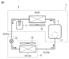
A refrigeration/air-conditioning device (1) comprises an outdoor unit (3) and an indoor unit (5). The outdoor unit (3) houses a compressor (7), a heat exchanger (10), and a liquid reservoir (11). The indoor unit (5) houses an expansion valve (15) and a heat exchanger (14). As a refrigeration cycle, the compressor (7), the heat exchanger (10), the liquid reservoir (11), the expansion valve (15) and the heat exchanger (14) are connected in this order by a refrigerant pipe (31). A fluorescent agent for detecting leakage of a refrigerant from the refrigerant pipe (31) and the like is added to refrigeration oil that circulates together with the refrigerant in the refrigerant pipe (31). A window (17) for checking the condition in the refrigeration cycle is formed in the refrigeration cycle.
Description
本開示は、冷凍空調装置に関する。
This disclosure relates to a freezing air conditioner.
冷凍空調装置においては、圧縮機、凝縮器、膨張弁および蒸発器が順次接続された冷媒回路(冷凍サイクル)を備え、冷媒回路内では、冷媒が循環する。その冷媒回路において、冷媒漏れが発生した場合には、冷媒が漏れている箇所を特定する作業が行われる。
The refrigerating and air-conditioning system is provided with a refrigerant circuit (refrigerant cycle) in which a compressor, a condenser, an expansion valve and an evaporator are sequentially connected, and the refrigerant circulates in the refrigerant circuit. When a refrigerant leak occurs in the refrigerant circuit, work is performed to identify the location where the refrigerant is leaking.
冷媒が漏れている箇所を特定する一つの手法として、発泡剤を吹き付ける手法がある(非特許文献1)。この手法では、冷媒が漏れていると疑われる箇所に発泡剤を吹き付けることによって、冷媒が漏れている箇所を特定することになる。冷媒が漏れている箇所に発泡剤が吹き付けられると、その箇所では気泡が発生する。
As one method of identifying the location where the refrigerant is leaking, there is a method of spraying a foaming agent (Non-Patent Document 1). In this method, the location where the refrigerant is leaking is identified by spraying the foaming agent on the portion where the refrigerant is suspected to be leaking. When the foaming agent is sprayed on the part where the refrigerant is leaking, bubbles are generated at that part.
冷媒が漏れている箇所を特定する他の手法として、冷媒ガス検知器を使用する手法がある(非特許文献2)。この手法では、冷媒ガス検知器を冷媒配管(回路)に当てながら、冷媒が漏れている箇所を特定することになる。
As another method for identifying the location where the refrigerant is leaking, there is a method using a refrigerant gas detector (Non-Patent Document 2). In this method, the refrigerant gas detector is applied to the refrigerant pipe (circuit) to identify the location where the refrigerant is leaking.
冷媒が漏れている箇所を特定するさらに他の手法として、蛍光剤を使用する手法がある(特許文献1)。この手法では、冷凍回路内を冷媒とともに循環する冷凍機油に、冷媒漏れを検知する蛍光剤を添加し、紫外線ランプにより紫外線を照射することによって、冷媒が漏れている箇所を特定することになる。冷媒が漏れている箇所では、冷媒および冷凍機油とともに漏れ出た蛍光剤が、紫外線の照射によって発光する。
As yet another method for identifying the location where the refrigerant is leaking, there is a method using a fluorescent agent (Patent Document 1). In this method, a fluorescent agent for detecting refrigerant leakage is added to refrigerating machine oil that circulates together with the refrigerant in the refrigeration circuit, and ultraviolet rays are irradiated by an ultraviolet lamp to identify the location where the refrigerant is leaking. At the location where the refrigerant is leaking, the fluorescent agent leaked together with the refrigerant and the refrigerating machine oil emits light by irradiation with ultraviolet rays.
冷媒が漏れている箇所を特定する手法のうち、特に、蛍光剤を使用して冷媒が漏れている箇所を特定する手法では、冷媒が漏れている箇所を確実に特定するために、冷媒とともに循環する冷凍機油に添加する蛍光剤の濃度を管理する必要がある。
Among the methods for identifying the location where the refrigerant is leaking, in particular, the method for identifying the location where the refrigerant is leaking using a fluorescent agent circulates together with the refrigerant in order to reliably identify the location where the refrigerant is leaking. It is necessary to control the concentration of the fluorescent agent added to the refrigerating machine oil.
本開示は、このような開発の一環でなされたものであり、その目的は、冷凍機油に添加された蛍光剤の濃度を容易に確認することができる冷凍空調装置を提供することである。
The present disclosure was made as part of such development, and an object thereof is to provide a refrigerating air conditioner capable of easily confirming the concentration of the fluorescent agent added to the refrigerating machine oil.
本開示に係る冷凍空調装置は、圧縮機、凝縮器、膨張弁および蒸発器が、順に冷媒配管によって接続された冷凍サイクルを有する冷凍空調装置であって、冷媒および冷凍機油と蛍光剤と窓部とを備えている。冷媒および冷凍機油は、冷凍サイクル内を循環する。蛍光剤は、冷媒とともに循環する冷凍機油に添加されている。窓部は、冷凍サイクルに設けられ、冷凍サイクル内の状態を確認する。
The refrigerating and air-conditioning apparatus according to the present disclosure is a refrigerating and air-conditioning apparatus having a refrigerating cycle in which a compressor, a condenser, an expansion valve and an evaporator are connected in order by a refrigerant pipe, and is a refrigerant, a refrigerating machine oil, a fluorescent agent, and a window. And have. Refrigerant and refrigerating machine oil circulate in the refrigeration cycle. The fluorescent agent is added to the refrigerating machine oil that circulates with the refrigerant. The window is provided in the refrigeration cycle to check the condition in the refrigeration cycle.
本開示に係る冷凍空調装置によれば、冷凍サイクルには、冷凍サイクル内の状態を確認するための窓部が設けられている。これにより、窓部に向けて紫外線を照射し、その紫外線の強度に対して、冷凍機油に添加されている蛍光剤の発光強度を測定することで、適正な濃度の蛍光剤が添加されているか否かを判断することができる。適正な濃度の蛍光剤が冷凍機油に添加されていることで、紫外線を照射することによって発せられる蛍光を確実に観測することができる。その結果、冷媒が漏れている箇所を確実に特定することができる。
According to the refrigerating and air-conditioning apparatus according to the present disclosure, the refrigerating cycle is provided with a window for checking the state in the refrigerating cycle. As a result, the window is irradiated with ultraviolet rays, and the emission intensity of the fluorescent agent added to the refrigerating machine oil is measured with respect to the intensity of the ultraviolet rays, so that the fluorescent agent having an appropriate concentration is added. It is possible to judge whether or not. By adding a fluorescent agent having an appropriate concentration to the refrigerating machine oil, it is possible to reliably observe the fluorescence emitted by irradiating with ultraviolet rays. As a result, the location where the refrigerant is leaking can be reliably identified.
(基本構造)
はじめに、各実施の形態に係る冷凍空調装置を構成する冷凍サイクル(冷媒回路)の基本構造の一例について説明する。図1に示すように、冷凍空調装置1は、室外機3と室内機5とを備えている。室外機3には、圧縮機7と、凝縮器9(または蒸発器)となる熱交換器10と、液溜め11とが収容されている。室内機5には、膨張弁15と、蒸発器13(または凝縮器)となる熱交換器14とが収容されている。 (Basic structure)
First, an example of the basic structure of the refrigerating cycle (refrigerant circuit) constituting the refrigerating and air-conditioning apparatus according to each embodiment will be described. As shown in FIG. 1, the refrigerating and air-conditioning device 1 includes an outdoor unit 3 and an indoor unit 5. The outdoor unit 3 houses a compressor 7, a heat exchanger 10 that serves as a condenser 9 (or an evaporator), and a liquid reservoir 11. The indoor unit 5 houses an expansion valve 15 and a heat exchanger 14 that serves as an evaporator 13 (or a condenser).
はじめに、各実施の形態に係る冷凍空調装置を構成する冷凍サイクル(冷媒回路)の基本構造の一例について説明する。図1に示すように、冷凍空調装置1は、室外機3と室内機5とを備えている。室外機3には、圧縮機7と、凝縮器9(または蒸発器)となる熱交換器10と、液溜め11とが収容されている。室内機5には、膨張弁15と、蒸発器13(または凝縮器)となる熱交換器14とが収容されている。 (Basic structure)
First, an example of the basic structure of the refrigerating cycle (refrigerant circuit) constituting the refrigerating and air-conditioning apparatus according to each embodiment will be described. As shown in FIG. 1, the refrigerating and air-
圧縮機7、熱交換器10、液溜め11、膨張弁15および熱交換器14が、順に冷媒配管31によって接続されている。室外機3と室内機5との間は、冷媒配管31の一部として、現地液配管31aと現地ガス配管31bとによって接続されている。冷媒が室外機3から室内機5へ流れる場合には、冷媒は、現地液配管31aを流れる。冷媒が室内機5から室外機3へ流れる場合には、冷媒は、現地ガス配管31bを流れる。
The compressor 7, the heat exchanger 10, the liquid reservoir 11, the expansion valve 15, and the heat exchanger 14 are connected in this order by the refrigerant pipe 31. The outdoor unit 3 and the indoor unit 5 are connected by a local liquid pipe 31a and a local gas pipe 31b as a part of the refrigerant pipe 31. When the refrigerant flows from the outdoor unit 3 to the indoor unit 5, the refrigerant flows through the local liquid pipe 31a. When the refrigerant flows from the indoor unit 5 to the outdoor unit 3, the refrigerant flows through the local gas pipe 31b.
圧縮機7は、吸入した低圧の冷媒を圧縮し、高圧の冷媒として吐出する流体機械である。圧縮機7では、たとえば、回転周波数がインバータ制御されていてもよい。また、圧縮機7として、一定の回転数で回転する圧縮機でもよい。
The compressor 7 is a fluid machine that compresses the sucked low-pressure refrigerant and discharges it as a high-pressure refrigerant. In the compressor 7, for example, the rotation frequency may be controlled by an inverter. Further, the compressor 7 may be a compressor that rotates at a constant rotation speed.
熱交換器10を凝縮器9として機能させる場合には、熱交換器10では、圧縮機7から吐出された冷媒と、たとえば、室外空気等の外気との間で熱交換が行われる。この熱交換によって、冷媒から外気に熱が放出される。また、熱交換器10(凝縮器9)としては、ファン12によって送り込まれる外気に、冷媒の熱を放出させる熱交換器(凝縮器)でもよい。
When the heat exchanger 10 functions as the condenser 9, the heat exchanger 10 exchanges heat between the refrigerant discharged from the compressor 7 and the outside air such as outdoor air. By this heat exchange, heat is released from the refrigerant to the outside air. Further, the heat exchanger 10 (condenser 9) may be a heat exchanger (condenser) that releases the heat of the refrigerant to the outside air sent by the fan 12.
膨張弁15は、凝縮器9から現地液配管31aを流れてきた冷媒を膨張させて減圧させる。膨張弁15として、たとえば、電子膨張弁、機械式の温度式自動膨張弁、または、キャピラリ等を用いることができる。
The expansion valve 15 expands the refrigerant flowing from the condenser 9 through the local liquid pipe 31a to reduce the pressure. As the expansion valve 15, for example, an electronic expansion valve, a mechanical temperature type automatic expansion valve, a capillary, or the like can be used.
熱交換器14を蒸発器13として機能させる場合には、熱交換器14では、膨張弁15によって減圧された冷媒と、たとえば、冷凍室内の空気等の室内空気との間で熱交換が行われる。この熱交換によって、室内空気から冷媒に熱が放出されて、室内空気が冷却される。また、熱交換器14(蒸発器13)としては、ファン16によって送り込まれる外気の熱を、冷媒に放出させる熱交換器(蒸発器)でもよい。
When the heat exchanger 14 functions as the evaporator 13, heat exchange is performed in the heat exchanger 14 between the refrigerant decompressed by the expansion valve 15 and indoor air such as air in the freezing chamber. .. By this heat exchange, heat is released from the indoor air to the refrigerant, and the indoor air is cooled. Further, the heat exchanger 14 (evaporator 13) may be a heat exchanger (evaporator) that releases the heat of the outside air sent by the fan 16 to the refrigerant.
次に、冷凍空調装置1の動作の一例として、室外機3の熱交換器10を凝縮器9として機能させるとともに、室内機5の熱交換器14を蒸発器13として機能させる動作について説明する。
Next, as an example of the operation of the refrigerating and air-conditioning device 1, an operation in which the heat exchanger 10 of the outdoor unit 3 functions as the condenser 9 and the heat exchanger 14 of the indoor unit 5 functions as the evaporator 13 will be described.
圧縮機7を駆動させることによって、圧縮機7から高温高圧のガス冷媒が吐出する。吐出した高温高圧のガス冷媒(単相)は、熱交換器10に流れ込む。熱交換器10は、凝縮器9として機能する。熱交換器10では、流れ込んだ冷媒と、ファン12によって供給される空気との間で熱交換が行われる。高温高圧のガス冷媒は、凝縮して高圧の液冷媒(単相)になる。
By driving the compressor 7, a high-temperature and high-pressure gas refrigerant is discharged from the compressor 7. The discharged high-temperature and high-pressure gas refrigerant (single-phase) flows into the heat exchanger 10. The heat exchanger 10 functions as a condenser 9. In the heat exchanger 10, heat exchange is performed between the flowing refrigerant and the air supplied by the fan 12. The high-temperature and high-pressure gas refrigerant condenses into a high-pressure liquid refrigerant (single-phase).
熱交換器10から送り出された高圧の液冷媒は、液溜め11を経て室内機5へ送り込まれて、膨張弁15を流れる。高圧の液冷媒は、膨張弁15によって、低圧のガス冷媒と液冷媒との二相状態の冷媒になる。二相状態の冷媒は、熱交換器14に流れ込む。熱交換器14では、流れ込んだ二相状態の冷媒と、ファン16によって供給される空気との間で熱交換が行われる。二相状態の冷媒は、液冷媒が蒸発して低圧のガス冷媒(単相)になる。この熱交換によって、室内が冷却されることになる。
The high-pressure liquid refrigerant sent out from the heat exchanger 10 is sent to the indoor unit 5 via the liquid reservoir 11 and flows through the expansion valve 15. The high-pressure liquid refrigerant becomes a two-phase refrigerant of a low-pressure gas refrigerant and a liquid refrigerant by the expansion valve 15. The two-phase refrigerant flows into the heat exchanger 14. In the heat exchanger 14, heat exchange is performed between the flowing two-phase refrigerant and the air supplied by the fan 16. In the two-phase state refrigerant, the liquid refrigerant evaporates to become a low-pressure gas refrigerant (single-phase). This heat exchange cools the room.
熱交換器14から送り出された低圧のガス冷媒は、圧縮機7に流れ込む。圧縮機7に流れ込んだ低圧のガス冷媒は、圧縮されて高温高圧のガス冷媒となって、再び圧縮機7から吐出する。以下、冷凍空調装置1では、このサイクルが繰り返される。
The low-pressure gas refrigerant sent out from the heat exchanger 14 flows into the compressor 7. The low-pressure gas refrigerant that has flowed into the compressor 7 is compressed to become a high-temperature and high-pressure gas refrigerant, and is discharged from the compressor 7 again. Hereinafter, in the refrigerating and air-conditioning device 1, this cycle is repeated.
なお、室外機3の熱交換器10を蒸発器として機能させるとともに、室内機5の熱交換器14を凝縮器として機能させる動作では、冷媒の流れが、上述した流れとは反対向きになる。いずれの動作の場合も、冷媒は、冷凍機油および蛍光剤ととともに、冷凍サイクル内を循環することになる。
In the operation in which the heat exchanger 10 of the outdoor unit 3 functions as an evaporator and the heat exchanger 14 of the indoor unit 5 functions as a condenser, the flow of the refrigerant is in the opposite direction to the above-mentioned flow. In either operation, the refrigerant will circulate in the refrigeration cycle along with the refrigerating machine oil and fluorescent agent.
冷凍空調装置1では、冷凍サイクル(冷媒回路)を循環する冷媒として、たとえば、単一冷媒、疑似共沸混合冷媒または非疑似共沸混合冷媒等が使用される。単一冷媒には、たとえば、R22またはR134a等がある。疑似共沸混合冷媒には、たとえば、R410AまたはR404A等がある。非疑似共沸混合冷媒には、たとえば、R407C等がある。
In the refrigerating and air-conditioning device 1, for example, a single refrigerant, a pseudo-azeotropic mixed refrigerant, a non-quasi-azeotropic mixed refrigerant, or the like is used as the refrigerant that circulates in the refrigerating cycle (refrigerant circuit). The single refrigerant includes, for example, R22 or R134a. Examples of the pseudo azeotropic mixed refrigerant include R410A and R404A. Examples of the non-quasi-azeotropic mixed refrigerant include R407C and the like.
その冷媒とともに冷凍サイクル内を循環する冷凍機油には、冷媒配管31等からの冷媒の漏れを検知するための蛍光剤が添加されている。冷媒が漏れている箇所を確実に特定するために、冷凍機油に添加する蛍光剤の濃度を管理する必要がある。
A fluorescent agent for detecting the leakage of the refrigerant from the refrigerant pipe 31 and the like is added to the refrigerating machine oil that circulates in the refrigerating cycle together with the refrigerant. It is necessary to control the concentration of the fluorescent agent added to the refrigerating machine oil in order to reliably identify the location where the refrigerant is leaking.
上述した冷凍空調装置1には、冷凍サイクル内の状態を確認するための窓部17が形成されている。窓部17には、サイトグラスが装着されている。窓部17に向けて紫外線を照射し、その紫外線の強度に対して蛍光剤の発光強度を測定することで、冷凍機油に添加された蛍光剤の濃度を見積もることができる。
The above-mentioned refrigerating and air-conditioning device 1 is formed with a window portion 17 for checking the state in the refrigerating cycle. A sight glass is attached to the window portion 17. The concentration of the fluorescent agent added to the refrigerating machine oil can be estimated by irradiating the window portion 17 with ultraviolet rays and measuring the emission intensity of the fluorescent agent with respect to the intensity of the ultraviolet rays.
蛍光剤の添加量(混入量)は、たとえば、冷凍機油に対して、0.25重量%程度である。以下、各実施の形態において、窓部17の配置等のバリエーションについて説明する。
The amount of the fluorescent agent added (mixed amount) is, for example, about 0.25% by weight with respect to the refrigerating machine oil. Hereinafter, variations such as the arrangement of the window portions 17 will be described in each embodiment.
実施の形態1.
実施の形態1に係る冷凍空調装置1の一例について説明する。図2に示すように、ここでは、冷凍サイクル内の状態を確認するための窓部17として、圧縮機7に窓部17aが設けられている。窓部17aは、たとえば、圧縮機7における油溜まり付近の油面が確認できる高さ(位置)に設けられている。Embodiment 1.
An example of the refrigerating and air-conditioning apparatus 1 according to the first embodiment will be described. As shown in FIG. 2, here, the compressor 7 is provided with the window portion 17a as the window portion 17 for confirming the state in the refrigeration cycle. The window portion 17a is provided, for example, at a height (position) where the oil level in the vicinity of the oil pool in the compressor 7 can be confirmed.
実施の形態1に係る冷凍空調装置1の一例について説明する。図2に示すように、ここでは、冷凍サイクル内の状態を確認するための窓部17として、圧縮機7に窓部17aが設けられている。窓部17aは、たとえば、圧縮機7における油溜まり付近の油面が確認できる高さ(位置)に設けられている。
An example of the refrigerating and air-
上述した冷凍空調装置1では、圧縮機7に設けられた窓部17aに向けて、たとえば、紫外線ランプから発せられる紫外線を照射する。紫外線を照射することで蛍光剤から発せられる蛍光の発光強度を測定する。その発光強度を基準の発光強度と比較することで、冷凍機油に添加されている蛍光剤の濃度が、適正範囲内にあるか否かが判断される。ここでは、蛍光剤の添加量(混入量)は、冷凍機油に対して、0.25重量%程度であるか否かが判断される。
In the above-mentioned refrigerating and air-conditioning device 1, for example, ultraviolet rays emitted from an ultraviolet lamp are irradiated toward the window portion 17a provided in the compressor 7. The emission intensity of fluorescence emitted from a fluorescent agent by irradiating with ultraviolet rays is measured. By comparing the emission intensity with the reference emission intensity, it is determined whether or not the concentration of the fluorescent agent added to the refrigerating machine oil is within an appropriate range. Here, it is determined whether or not the amount of the fluorescent agent added (mixed amount) is about 0.25% by weight with respect to the refrigerating machine oil.
冷凍空調装置1において、冷媒漏れが発生したと判断される場合には、冷媒が漏れている箇所では、冷媒とともに、蛍光剤が添加された冷凍機油も漏れ出ることになる。その冷凍機油に、適正な濃度(添加量)の蛍光剤が添加されていることで、紫外線を照射することによって発せられる蛍光を確実に観測することができる。その結果、冷媒が漏れている箇所を確実に特定することができる。
When it is determined that a refrigerant leak has occurred in the refrigerating and air-conditioning device 1, the refrigerating machine oil to which the fluorescent agent is added leaks together with the refrigerant at the place where the refrigerant leaks. By adding a fluorescent agent having an appropriate concentration (addition amount) to the refrigerating machine oil, it is possible to reliably observe the fluorescence emitted by irradiating with ultraviolet rays. As a result, the location where the refrigerant is leaking can be reliably identified.
実施の形態2.
実施の形態2に係る冷凍空調装置1の一例について説明する。図3に示すように、圧縮機7には、冷凍サイクル内に供給する冷凍機油を貯溜するオイルレギュレータ19が接続されている。そのオイルレギュレータ19に、冷凍サイクル内の状態を確認するための窓部17bが設けられている。なお、図3では、圧縮機7にも窓部17aが設けられている冷凍サイクルを示しているが、圧縮機7に窓部17aが設けられていない冷凍サイクルでもよい。 Embodiment 2.
An example of the refrigerating and air-conditioning apparatus 1 according to the second embodiment will be described. As shown in FIG. 3, an oil regulator 19 for storing refrigerating machine oil supplied in the refrigerating cycle is connected to the compressor 7. The oil regulator 19 is provided with a window portion 17b for checking the state in the refrigeration cycle. Although FIG. 3 shows a refrigeration cycle in which the compressor 7 is also provided with the window portion 17a, a refrigeration cycle in which the compressor 7 is not provided with the window portion 17a may be used.
実施の形態2に係る冷凍空調装置1の一例について説明する。図3に示すように、圧縮機7には、冷凍サイクル内に供給する冷凍機油を貯溜するオイルレギュレータ19が接続されている。そのオイルレギュレータ19に、冷凍サイクル内の状態を確認するための窓部17bが設けられている。なお、図3では、圧縮機7にも窓部17aが設けられている冷凍サイクルを示しているが、圧縮機7に窓部17aが設けられていない冷凍サイクルでもよい。 Embodiment 2.
An example of the refrigerating and air-
上述した冷凍空調装置1では、オイルレギュレータ19に設けられた窓部17bに向けて紫外線を照射することで、蛍光剤から発せられる蛍光の発光強度を測定する。その発光強度を基準の発光強度と比較することで、冷凍機油に添加されている蛍光剤の濃度が、適正範囲内にあるか否かが判断される。
In the refrigerating and air-conditioning device 1 described above, the emission intensity of fluorescence emitted from the fluorescent agent is measured by irradiating the window portion 17b provided in the oil regulator 19 with ultraviolet rays. By comparing the emission intensity with the reference emission intensity, it is determined whether or not the concentration of the fluorescent agent added to the refrigerating machine oil is within an appropriate range.
冷凍空調装置1において、冷媒漏れが発生したと判断される場合には、冷媒が漏れている箇所では、冷媒とともに、蛍光剤が添加された冷凍機油も漏れ出ることになる。その冷凍機油に、適正な濃度(添加量)の蛍光剤が添加されていることで、紫外線を照射することによって発せられる蛍光を確実に観測することができる。その結果、冷媒が漏れている箇所を確実に特定することができる。
When it is determined that a refrigerant leak has occurred in the refrigerating and air-conditioning device 1, the refrigerating machine oil to which the fluorescent agent is added leaks together with the refrigerant at the place where the refrigerant leaks. By adding a fluorescent agent having an appropriate concentration (addition amount) to the refrigerating machine oil, it is possible to reliably observe the fluorescence emitted by irradiating with ultraviolet rays. As a result, the location where the refrigerant is leaking can be reliably identified.
実施の形態3.
実施の形態3に係る冷凍空調装置1の一例について説明する。図4に示すように、室外機3に配置された液溜め11と室内機5との間の冷媒配管31に、冷凍サイクル内の状態を確認するための窓部17cが設けられている。室外機3の熱交換器10を凝縮器9として機能させるとともに、室内機5の熱交換器14を蒸発器13として機能させる動作の場合には、窓部17cは、凝縮器9(熱交換器10)に対して、冷媒の流れの下流側に配置されており、冷媒配管31における室外機3の出口側に配置されていることになる。Embodiment 3.
An example of the refrigerating and air-conditioning apparatus 1 according to the third embodiment will be described. As shown in FIG. 4, the refrigerant pipe 31 between the liquid reservoir 11 and the indoor unit 5 arranged in the outdoor unit 3 is provided with a window portion 17c for checking the state in the refrigeration cycle. In the case of the operation in which the heat exchanger 10 of the outdoor unit 3 functions as the condenser 9 and the heat exchanger 14 of the indoor unit 5 functions as the evaporator 13, the window portion 17c is the condenser 9 (heat exchanger 9). 10), it is arranged on the downstream side of the flow of the refrigerant, and is arranged on the outlet side of the outdoor unit 3 in the refrigerant pipe 31.
実施の形態3に係る冷凍空調装置1の一例について説明する。図4に示すように、室外機3に配置された液溜め11と室内機5との間の冷媒配管31に、冷凍サイクル内の状態を確認するための窓部17cが設けられている。室外機3の熱交換器10を凝縮器9として機能させるとともに、室内機5の熱交換器14を蒸発器13として機能させる動作の場合には、窓部17cは、凝縮器9(熱交換器10)に対して、冷媒の流れの下流側に配置されており、冷媒配管31における室外機3の出口側に配置されていることになる。
An example of the refrigerating and air-
なお、図4では、圧縮機7に窓部17aが設けられ、オイルレギュレータ19に窓部17bが設けられている冷凍サイクルを示している。窓部17としては、窓部17aおよび窓部17bの双方が設けられていない冷凍サイクル装置でもよい。また、窓部17aおよび窓部17bのいずれか一方の窓部17が設けられていない冷凍サイクルでもよい。
Note that FIG. 4 shows a refrigeration cycle in which the compressor 7 is provided with the window portion 17a and the oil regulator 19 is provided with the window portion 17b. The window portion 17 may be a refrigeration cycle device in which both the window portion 17a and the window portion 17b are not provided. Further, a refrigeration cycle may be used in which the window portion 17 of either the window portion 17a or the window portion 17b is not provided.
上述した冷凍空調装置1では、室外機3の出口側に設けられた窓部17cに向けて紫外線を照射することで、蛍光剤から発せられる蛍光の発光強度を測定する。その発光強度を基準の発光強度と比較することで、冷凍機油に添加されている蛍光剤の濃度が、適正範囲内にあるか否かが判断される。
In the refrigerating and air-conditioning device 1 described above, the emission intensity of fluorescence emitted from the fluorescent agent is measured by irradiating the window portion 17c provided on the outlet side of the outdoor unit 3 with ultraviolet rays. By comparing the emission intensity with the reference emission intensity, it is determined whether or not the concentration of the fluorescent agent added to the refrigerating machine oil is within an appropriate range.
冷凍空調装置1において、冷媒漏れが発生したと判断される場合には、冷媒が漏れている箇所では、冷媒とともに、蛍光剤が添加された冷凍機油も漏れ出ることになる。その冷凍機油に、適正な濃度(添加量)の蛍光剤が添加されていることで、紫外線を照射することによって発せられる蛍光を確実に観測することができる。その結果、冷媒が漏れている箇所を確実に特定することができる。
When it is determined that a refrigerant leak has occurred in the refrigerating and air-conditioning device 1, the refrigerating machine oil to which the fluorescent agent is added leaks together with the refrigerant at the place where the refrigerant leaks. By adding a fluorescent agent having an appropriate concentration (addition amount) to the refrigerating machine oil, it is possible to reliably observe the fluorescence emitted by irradiating with ultraviolet rays. As a result, the location where the refrigerant is leaking can be reliably identified.
実施の形態4.
実施の形態4に係る冷凍空調装置1の一例について説明する。図5に示すように、圧縮機7に対して、冷媒の流れの上流側に、冷凍サイクル内を確認するための窓部17dが設けられている。室外機3の熱交換器10を凝縮器9として機能させるとともに、室内機5の熱交換器14を蒸発器13として機能させる動作の場合には、窓部17dは、冷媒配管31における室外機3の入口側に配置されていることになる。Embodiment 4.
An example of the refrigerating and air-conditioning apparatus 1 according to the fourth embodiment will be described. As shown in FIG. 5, a window portion 17d for checking the inside of the refrigeration cycle is provided on the upstream side of the flow of the refrigerant with respect to the compressor 7. In the case of the operation in which the heat exchanger 10 of the outdoor unit 3 functions as the condenser 9 and the heat exchanger 14 of the indoor unit 5 functions as the evaporator 13, the window portion 17d is the outdoor unit 3 in the refrigerant pipe 31. It will be located on the entrance side of.
実施の形態4に係る冷凍空調装置1の一例について説明する。図5に示すように、圧縮機7に対して、冷媒の流れの上流側に、冷凍サイクル内を確認するための窓部17dが設けられている。室外機3の熱交換器10を凝縮器9として機能させるとともに、室内機5の熱交換器14を蒸発器13として機能させる動作の場合には、窓部17dは、冷媒配管31における室外機3の入口側に配置されていることになる。
An example of the refrigerating and air-
なお、図5では、圧縮機7に窓部17aが設けられ、オイルレギュレータ19に窓部17bが設けられ、室外機の出口側に窓部17cが設けられた冷凍サイクルを示している。窓部17としては、窓部17a、窓部17bおよび窓部17cの全部が設けられていない冷凍サイクル装置でもよい。また、窓部17a、窓部17bおよび窓部17cのいずれか2つの窓部17が設けられていない冷凍サイクルでもよい。さらに、窓部17a、窓部17bおよび窓部17cのいずれか1つの窓部17が設けられていない冷凍サイクルでもよい。
Note that FIG. 5 shows a refrigeration cycle in which the compressor 7 is provided with the window portion 17a, the oil regulator 19 is provided with the window portion 17b, and the window portion 17c is provided on the outlet side of the outdoor unit. The window portion 17 may be a refrigeration cycle device in which all of the window portion 17a, the window portion 17b, and the window portion 17c are not provided. Further, a refrigeration cycle in which any two window portions 17 of the window portion 17a, the window portion 17b, and the window portion 17c are not provided may be used. Further, a refrigeration cycle may be used in which the window portion 17 of any one of the window portion 17a, the window portion 17b and the window portion 17c is not provided.
上述した冷凍空調装置1では、室外機3の入口側に設けられた窓部17dに向けて紫外線を照射することで、蛍光剤から発せられる蛍光の発光強度を測定する。その発光強度を基準の発光強度と比較することで、冷凍機油に添加されている蛍光剤の濃度が、適正範囲内にあるか否かが判断される。
In the refrigerating and air-conditioning device 1 described above, the emission intensity of fluorescence emitted from the fluorescent agent is measured by irradiating the window portion 17d provided on the inlet side of the outdoor unit 3 with ultraviolet rays. By comparing the emission intensity with the reference emission intensity, it is determined whether or not the concentration of the fluorescent agent added to the refrigerating machine oil is within an appropriate range.
冷凍空調装置1において、冷媒漏れが発生したと判断される場合には、冷媒が漏れている箇所では、冷媒とともに、蛍光剤が添加された冷凍機油も漏れ出ることになる。その冷凍機油に、適正な濃度(添加量)の蛍光剤が添加されていることで、紫外線を照射することによって発せられる蛍光を確実に観測することができる。その結果、冷媒が漏れている箇所を確実に特定することができる。また、冷凍サイクル内の冷媒の漏れを特定するために、蛍光剤を冷凍サイクル内に循環させる必要がある。上述した冷凍空調装置1では、窓部17dが、圧縮機7の吸入側に配置されていることで、蛍光剤が冷凍サイクル内を循環していることを確認することができる。
When it is determined that a refrigerant leak has occurred in the refrigerating and air-conditioning device 1, the refrigerating machine oil to which the fluorescent agent is added leaks together with the refrigerant at the place where the refrigerant leaks. By adding a fluorescent agent having an appropriate concentration (addition amount) to the refrigerating machine oil, it is possible to reliably observe the fluorescence emitted by irradiating with ultraviolet rays. As a result, the location where the refrigerant is leaking can be reliably identified. In addition, it is necessary to circulate the fluorescent agent in the refrigeration cycle in order to identify the leakage of the refrigerant in the refrigeration cycle. In the above-mentioned refrigerating and air-conditioning device 1, since the window portion 17d is arranged on the suction side of the compressor 7, it can be confirmed that the fluorescent agent circulates in the refrigerating cycle.
実施の形態5.
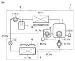
実施の形態5に係る冷凍空調装置1の一例について説明する。図6に示すように、室外機3において、冷凍機油に添加する蛍光剤を冷凍サイクル内に供給する供給口21が、たとえば、2ヶ所設けられている。ここでは、オイルレギュレータ19に供給口21aが設けられ、圧縮機7に供給口21bが設けられている。Embodiment 5.
An example of the refrigerating and air-conditioning apparatus 1 according to the fifth embodiment will be described. As shown in FIG. 6, in the outdoor unit 3, for example, two supply ports 21 for supplying the fluorescent agent to be added to the refrigerating machine oil into the refrigerating cycle are provided. Here, the oil regulator 19 is provided with the supply port 21a, and the compressor 7 is provided with the supply port 21b.
実施の形態5に係る冷凍空調装置1の一例について説明する。図6に示すように、室外機3において、冷凍機油に添加する蛍光剤を冷凍サイクル内に供給する供給口21が、たとえば、2ヶ所設けられている。ここでは、オイルレギュレータ19に供給口21aが設けられ、圧縮機7に供給口21bが設けられている。
An example of the refrigerating and air-
上述した冷凍空調装置1では、圧縮機7等に設けられた窓部17aに向けて紫外線を照射することで、蛍光剤から発せられる蛍光の発光強度を測定する。その発光強度を基準の発光強度と比較することで、冷凍機油に添加されている蛍光剤の濃度が、適正範囲内にあるか否かが判断される。
In the refrigerating and air-conditioning device 1 described above, the emission intensity of fluorescence emitted from the fluorescent agent is measured by irradiating the window portion 17a provided in the compressor 7 or the like with ultraviolet rays. By comparing the emission intensity with the reference emission intensity, it is determined whether or not the concentration of the fluorescent agent added to the refrigerating machine oil is within an appropriate range.
このとき、冷凍機油に添加されている蛍光剤の濃度が、適正範囲よりも低いと判断される場合がある。そこで、供給口21aまたは供給口21bから蛍光剤を冷凍サイクル内に供給する。紫外線を照射して窓部17から発せられる蛍光の発光強度が、適正範囲に入れば、蛍光剤の供給を止めればよい。
At this time, it may be determined that the concentration of the fluorescent agent added to the refrigerating machine oil is lower than the appropriate range. Therefore, the fluorescent agent is supplied into the refrigeration cycle from the supply port 21a or the supply port 21b. If the emission intensity of the fluorescence emitted from the window 17 by irradiating with ultraviolet rays falls within an appropriate range, the supply of the fluorescent agent may be stopped.
これにより、適正な濃度(添加量)の蛍光剤が冷凍機油に添加されていることで、紫外線を照射することによって発せられる蛍光を確実に観測することができる。その結果、冷媒が漏れている箇所を確実に特定することができる。
As a result, by adding a fluorescent agent having an appropriate concentration (addition amount) to the refrigerating machine oil, it is possible to reliably observe the fluorescence emitted by irradiating with ultraviolet rays. As a result, the location where the refrigerant is leaking can be reliably identified.
発明者らは、窓部17の位置および蛍光剤の供給口21の位置について、紫外線の照射、蛍光の測定および蛍光剤の供給等の作業のしやすさ、コスト等の観点から種々検討を行った。その結果、図7に示すように、窓部17としては、オイルレギュレータ19に窓部17bを設け、室外機3の出口側に窓部17cを設けることが好ましいと判断した。また、供給口21としては、オイルレギュレータ19に供給口21aを設けることが好ましいと判断した。
The inventors have conducted various studies on the position of the window portion 17 and the position of the fluorescent agent supply port 21 from the viewpoints of ease of work such as irradiation of ultraviolet rays, measurement of fluorescence, and supply of fluorescent agent, cost, and the like. rice field. As a result, as shown in FIG. 7, it was determined that it is preferable that the window portion 17 is provided with the window portion 17b in the oil regulator 19 and the window portion 17c is provided on the outlet side of the outdoor unit 3. Further, as the supply port 21, it was determined that it is preferable to provide the supply port 21a in the oil regulator 19.
これについて、もう少し詳しく説明する。オイルレギュレータ19は、冷凍機油を貯溜するタンクである。タンク内には、冷凍機油を供給する供給配管、冷凍機油の油面を調整する部材としての浮き、浮きによって供給配管を開閉して供給される冷凍機油の量を調整する調整機構が配置されている。これにより、タンク内には、所望量の冷凍機油が貯溜されることになる。
This will be explained in a little more detail. The oil regulator 19 is a tank for storing refrigerating machine oil. Inside the tank, a supply pipe for supplying refrigerating machine oil, a float as a member for adjusting the oil level of the refrigerating machine oil, and an adjusting mechanism for adjusting the amount of refrigerating machine oil supplied by opening and closing the supply pipe by floating are arranged. There is. As a result, a desired amount of refrigerating machine oil is stored in the tank.
ここで、オイルレギュレータ19のタンク内の圧力と、圧縮機7(吸入側)の圧力とは同じ圧力になるため、タンク内の冷凍機油の油面の位置と、圧縮機7内の冷凍機油の油面の位置とは同じ位置(高さ)になる。
Here, since the pressure in the tank of the oil regulator 19 and the pressure in the compressor 7 (suction side) are the same, the position of the oil level of the refrigerating machine oil in the tank and the pressure of the refrigerating machine oil in the compressor 7 It will be at the same position (height) as the position of the oil level.
このため、オイルレギュレータ19のタンク内の油面の位置および圧縮機内の油面の位置のそれぞれを確認するには、オイルレギュレータ19および圧縮機7のいずれか一方に窓部17のサイトグラスを設ければよい。成形性(製造のしやすさ)および蛍光剤の供給口21から蛍光剤を供給できたか否かを確認する点を考慮すると、オイルレギュレータ19のタンクに、窓部17bのサイトグラスを、油面が見える位置に配置することがより好ましいと考えられる。なお、圧縮機7に窓部17aを配置することで、冷凍機油の油面の位置をより的確に確認することができる。
Therefore, in order to confirm the position of the oil level in the tank of the oil regulator 19 and the position of the oil level in the compressor, a sight glass of the window portion 17 is provided on either one of the oil regulator 19 and the compressor 7. Just do it. Considering the formability (ease of manufacture) and the point of confirming whether or not the fluorescent agent could be supplied from the fluorescent agent supply port 21, the sight glass of the window portion 17b was placed in the tank of the oil regulator 19 and the oil level was increased. It is considered more preferable to arrange the position so that the can be seen. By arranging the window portion 17a in the compressor 7, the position of the oil level of the refrigerating machine oil can be confirmed more accurately.
実施の形態6.
実施の形態6に係る冷凍空調装置1の一例について説明する。上述したように、各実施の形態に係る冷凍空調装置1では、窓部17に向けて紫外線を照射することによって、蛍光剤から発せられる蛍光の発光強度が測定される。このとき、蛍光剤から発せられる蛍光を捉えるのは、周囲が明るいところよりも、周囲が暗いところの方が容易である。 Embodiment 6.
An example of the refrigerating and air-conditioning apparatus 1 according to the sixth embodiment will be described. As described above, in the refrigerating and air-conditioning apparatus 1 according to each embodiment, the emission intensity of fluorescence emitted from the fluorescent agent is measured by irradiating the window portion 17 with ultraviolet rays. At this time, it is easier to capture the fluorescence emitted from the fluorescent agent in a place where the surroundings are dark than in a place where the surroundings are bright.
実施の形態6に係る冷凍空調装置1の一例について説明する。上述したように、各実施の形態に係る冷凍空調装置1では、窓部17に向けて紫外線を照射することによって、蛍光剤から発せられる蛍光の発光強度が測定される。このとき、蛍光剤から発せられる蛍光を捉えるのは、周囲が明るいところよりも、周囲が暗いところの方が容易である。 Embodiment 6.
An example of the refrigerating and air-
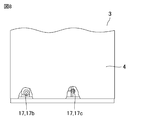
このことから、窓部17の位置としては、日の光が直接差し込まない位置が好ましい。そこで、図8に示すように、窓部17としては、たとえば、室外機3の筐体4内に配置させることが好ましい。図8では、たとえば、オイルレギュレータに設けられた窓部17bと、室外機3の出口側に設けられた窓部17cとが示されている。
For this reason, the position of the window portion 17 is preferably a position where sunlight does not directly enter. Therefore, as shown in FIG. 8, it is preferable that the window portion 17 is arranged in, for example, the housing 4 of the outdoor unit 3. In FIG. 8, for example, a window portion 17b provided in the oil regulator and a window portion 17c provided on the outlet side of the outdoor unit 3 are shown.
窓部17b、17cのそれぞれのサイトグラスは、メンテナンス時も使用される。このため、窓部17b、17cは、筐体4内のメンテナンスがしやすい位置に配置されることが望ましく、たとえば、メンテナンス用の板金(扉)を開けて直ぐに確認できる位置に配置させることが望ましい。
The sight glasses of the windows 17b and 17c are also used during maintenance. Therefore, it is desirable that the windows 17b and 17c are arranged in a position inside the housing 4 where maintenance is easy. For example, it is desirable to arrange the windows 17b and 17c in a position where the maintenance sheet metal (door) can be opened and immediately confirmed. ..
また、筐体4には、窓部17cを臨む開口部4bと、窓部17bを臨む開口部4aとが設けられていることが望ましい。開口部4a、4bから紫外線を照射し、周囲が暗い所に位置する窓部17b、17cから発せられる蛍光を確認することで、扉等を開けることなく、蛍光剤の濃度をより精度よく測定することができる。
Further, it is desirable that the housing 4 is provided with an opening 4b facing the window 17c and an opening 4a facing the window 17b. By irradiating ultraviolet rays from the openings 4a and 4b and confirming the fluorescence emitted from the windows 17b and 17c located in a dark place, the concentration of the fluorescent agent can be measured more accurately without opening the door or the like. be able to.
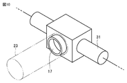
なお、窓部17を筐体4内に配置させる他に、図10に示すように、たとえば、窓部17に筒状体23を配置し、窓部17の周囲を暗くするようにしてもよい。筒状体23を配置することによっても、蛍光剤の濃度をより精度よく測定することができる。
In addition to arranging the window portion 17 in the housing 4, for example, as shown in FIG. 10, a tubular body 23 may be arranged in the window portion 17 to darken the periphery of the window portion 17. .. By arranging the tubular body 23, the concentration of the fluorescent agent can be measured more accurately.
冷凍サイクル内を循環する蛍光剤は、冷凍機油の温度が低下すると固化して析出するおそれがある。たとえば、液バック現象が生じた場合には、冷媒の蒸発温度が低い場合(たとえば、-45℃)には、蛍光剤が析出するおそれがある。蛍光剤が析出すると、冷凍機油に蛍光剤が含まれなくなるか、冷凍機油に含まれる蛍光剤の量が少なくなる。液バック現象とは、たとえば、蒸発器の霜付きまたは風量の大幅な低下等によって、熱交換が良好に行われなくなった場合に、冷媒が、液体と気体との二相状態で圧縮機に吸入される現象をいう。
The fluorescent agent that circulates in the refrigeration cycle may solidify and precipitate when the temperature of the refrigerating machine oil drops. For example, when the liquid back phenomenon occurs, the fluorescent agent may precipitate when the evaporation temperature of the refrigerant is low (for example, −45 ° C.). When the fluorescent agent is precipitated, the refrigerating machine oil does not contain the fluorescent agent, or the amount of the fluorescent agent contained in the refrigerating machine oil decreases. The liquid back phenomenon is, for example, when heat exchange is not performed well due to frosting of the evaporator or a drastic decrease in air volume, the refrigerant is sucked into the compressor in a two-phase state of liquid and gas. The phenomenon that is done.
このため、冷凍サイクル内において冷媒が漏れている箇所を、蛍光剤の発光によって特定することが難しくなることがある。そこで、冷媒が漏れていると判断される場合であって、その直前に液バックが生じ、蛍光剤の析出が確認された場合には、冷媒の温度を上げて、蛍光剤の析出をなくしたうえで、紫外線を照射することによって冷媒が漏れている箇所を特定することが望ましい。なお、蛍光剤への紫外線の照射と、蛍光剤から発せられる蛍光の測定については、作業員が行うようにしてもよいし、蛍光の強度を測定するセンサ等を用いて、測定するようにしてもよい。
For this reason, it may be difficult to identify the location where the refrigerant is leaking in the refrigeration cycle by the light emission of the fluorescent agent. Therefore, when it is determined that the refrigerant is leaking, liquid backing occurs immediately before that, and precipitation of the fluorescent agent is confirmed, the temperature of the refrigerant is raised to eliminate the precipitation of the fluorescent agent. In addition, it is desirable to identify the location where the refrigerant is leaking by irradiating with ultraviolet rays. The irradiation of the fluorescent agent with ultraviolet rays and the measurement of the fluorescence emitted from the fluorescent agent may be performed by an operator, or may be measured by using a sensor or the like for measuring the fluorescence intensity. May be good.
上述した各実施の形態では、室外機3の熱交換器10を凝縮器として機能させるとともに、室内機5の熱交換器14を蒸発器として機能させる場合について説明した。冷凍空調装置1としては、室外機3の熱交換器10を蒸発器として機能させるとともに、室内機5の熱交換器14を凝縮器として機能させてもよい。この場合には、冷媒の流れは、上述した冷媒の流れとは反対の流れになるため、必要に応じて、窓部を設ける位置を適宜変更してよい。このような場合においても、蛍光剤の濃度を測定することができる。
In each of the above-described embodiments, the case where the heat exchanger 10 of the outdoor unit 3 functions as a condenser and the heat exchanger 14 of the indoor unit 5 functions as an evaporator has been described. As the refrigerating and air-conditioning device 1, the heat exchanger 10 of the outdoor unit 3 may function as an evaporator, and the heat exchanger 14 of the indoor unit 5 may function as a condenser. In this case, since the flow of the refrigerant is opposite to the flow of the refrigerant described above, the position where the window portion is provided may be appropriately changed as necessary. Even in such a case, the concentration of the fluorescent agent can be measured.
各実施の形態において説明した冷凍空調装置については、必要に応じて種々組み合わせることが可能である。
The refrigerating and air-conditioning devices described in each embodiment can be combined in various ways as needed.
今回開示された実施の形態は例示であってこれに制限されるものではない。本開示は上記で説明した範囲ではなく、請求の範囲によって示され、請求の範囲と均等の意味および範囲でのすべての変更が含まれることが意図される。
The embodiment disclosed this time is an example and is not limited to this. The present disclosure is set forth by the claims, not the scope described above, and is intended to include all modifications in the sense and scope equivalent to the claims.
本開示は、冷媒が循環する冷凍サイクルを備えた冷凍空調装置に有効に利用される。
This disclosure is effectively used in a freezing air conditioner equipped with a freezing cycle in which a refrigerant circulates.
1 冷凍空調装置、3 室外機、4 筐体、4a、4b 開口部、5 室内機、7 圧縮機、9 凝縮器、10 熱交換器、11 液溜め、12 ファン、13 蒸発器、14 熱交換器、15 膨張弁、16 ファン、17、17a、17b、17c、17d 窓部、19 オイルレギュレータ、21、21a、21b 供給口、23 筒状体、31 冷媒配管、31a 現地液配管、31b 現地ガス配管。
1 Refrigerating air conditioner, 3 Outdoor unit, 4 Housing, 4a, 4b opening, 5 Indoor unit, 7 Compressor, 9 Condenser, 10 Heat exchanger, 11 Liquid reservoir, 12 Fan, 13 Evaporator, 14 Heat exchange Vessel, 15 expansion valve, 16 fan, 17, 17a, 17b, 17c, 17d window, 19 oil regulator, 21, 21a, 21b supply port, 23 tubular body, 31 refrigerant pipe, 31a local liquid pipe, 31b local gas Plumbing.
Claims (9)
- 圧縮機、凝縮器、膨張弁および蒸発器が、順に冷媒配管によって接続された冷凍サイクルを有する冷凍空調装置であって、
前記冷凍サイクル内を循環する冷媒および冷凍機油と、
前記冷媒とともに循環する前記冷凍機油に添加された蛍光剤と、
前記冷凍サイクルに設けられ、前記冷凍サイクル内の状態を確認するための窓部と
を備えた、冷凍空調装置。 A refrigerating air conditioner having a refrigerating cycle in which a compressor, a condenser, an expansion valve and an evaporator are connected in order by a refrigerant pipe.
Refrigerant and refrigerating machine oil circulating in the refrigeration cycle,
A fluorescent agent added to the refrigerating machine oil that circulates with the refrigerant, and
A freezing air conditioner provided in the freezing cycle and provided with a window for checking the state in the freezing cycle. - 前記窓部は、前記圧縮機に配置された、請求項1記載の冷凍空調装置。 The refrigerating and air-conditioning device according to claim 1, wherein the window portion is arranged in the compressor.
- 前記窓部は、前記凝縮器に対して、前記冷媒の流れの下流側に配置された、請求項1または2に記載の冷凍空調装置。 The refrigerating and air-conditioning apparatus according to claim 1 or 2, wherein the window portion is arranged on the downstream side of the flow of the refrigerant with respect to the condenser.
- 前記窓部は、前記圧縮機に対して、前記冷媒の流れの上流側に配置された、請求項1~3のいずれか1項に記載の冷凍空調装置。 The refrigerating and air-conditioning device according to any one of claims 1 to 3, wherein the window portion is arranged on the upstream side of the flow of the refrigerant with respect to the compressor.
- 前記冷凍サイクルは、前記圧縮機に接続され、前記冷凍サイクル内に供給する前記冷凍機油を貯溜するオイルレギュレータを含み、
前記窓部は、前記オイルレギュレータに配置された、請求項1~4のいずれか1項に記載の冷凍空調装置。 The refrigeration cycle includes an oil regulator that is connected to the compressor and stores the refrigerating machine oil that is supplied into the refrigeration cycle.
The refrigerating and air-conditioning apparatus according to any one of claims 1 to 4, wherein the window portion is arranged in the oil regulator. - 前記オイルレギュレータには、前記冷凍サイクル内に前記蛍光剤を供給する第1蛍光剤供給口が設けられた、請求項5記載の冷凍空調装置。 The refrigerating and air-conditioning apparatus according to claim 5, wherein the oil regulator is provided with a first fluorescent agent supply port for supplying the fluorescent agent in the refrigeration cycle.
- 前記冷凍サイクルは、前記冷凍サイクル内に前記蛍光剤を供給する第2蛍光剤供給口を有する、請求項1~6のいずれか1項に記載の冷凍空調装置。 The refrigerating and air-conditioning apparatus according to any one of claims 1 to 6, wherein the refrigerating cycle has a second fluorescent agent supply port for supplying the fluorescent agent in the refrigerating cycle.
- 前記第2蛍光剤供給口は、前記圧縮機に設けられた、請求項7記載の冷凍空調装置。 The refrigerating and air-conditioning device according to claim 7, wherein the second fluorescent agent supply port is provided in the compressor.
- 前記圧縮機および前記凝縮器は、筺体内に配置され、
前記窓部は、前記筺体内に配置され、
前記筺体には、前記窓部を臨む開口部が形成された、請求項1~8のいずれか1項に記載の冷凍空調装置。 The compressor and the condenser are placed inside the housing and
The window portion is arranged inside the housing, and the window portion is arranged inside the housing.
The refrigerating and air-conditioning apparatus according to any one of claims 1 to 8, wherein an opening facing the window is formed in the housing.
Priority Applications (3)
| Application Number | Priority Date | Filing Date | Title |
|---|---|---|---|
| PCT/JP2020/011708 WO2021186549A1 (en) | 2020-03-17 | 2020-03-17 | Refrigeration/air-conditioning device |
| CN202080098342.5A CN115280083A (en) | 2020-03-17 | 2020-03-17 | Refrigerating air conditioner |
| JP2022508654A JP7357763B2 (en) | 2020-03-17 | 2020-03-17 | Refrigeration and air conditioning equipment |
Applications Claiming Priority (1)
| Application Number | Priority Date | Filing Date | Title |
|---|---|---|---|
| PCT/JP2020/011708 WO2021186549A1 (en) | 2020-03-17 | 2020-03-17 | Refrigeration/air-conditioning device |
Publications (1)
| Publication Number | Publication Date |
|---|---|
| WO2021186549A1 true WO2021186549A1 (en) | 2021-09-23 |
Family
ID=77770910
Family Applications (1)
| Application Number | Title | Priority Date | Filing Date |
|---|---|---|---|
| PCT/JP2020/011708 WO2021186549A1 (en) | 2020-03-17 | 2020-03-17 | Refrigeration/air-conditioning device |
Country Status (3)
| Country | Link |
|---|---|
| JP (1) | JP7357763B2 (en) |
| CN (1) | CN115280083A (en) |
| WO (1) | WO2021186549A1 (en) |
Cited By (1)
| Publication number | Priority date | Publication date | Assignee | Title |
|---|---|---|---|---|
| WO2023084771A1 (en) * | 2021-11-15 | 2023-05-19 | 三菱電機株式会社 | Accumulator and refrigeration cycle device |
Citations (6)
| Publication number | Priority date | Publication date | Assignee | Title |
|---|---|---|---|---|
| JPS58221353A (en) * | 1982-06-17 | 1983-12-23 | 三菱電機株式会社 | Feeder for oil to refrigerator |
| JPH10288430A (en) * | 1997-04-10 | 1998-10-27 | Denso Corp | Flow rate detecting device |
| JP2003215040A (en) * | 2002-01-24 | 2003-07-30 | Daikin Ind Ltd | State detector for lubricating oil in refrigerating cycle |
| JP2006275325A (en) * | 2005-03-28 | 2006-10-12 | Sanyo Electric Co Ltd | Compressor unit |
| JP2010078292A (en) * | 2008-09-29 | 2010-04-08 | Chino Corp | Oil circulation rate measuring device |
| WO2018225263A1 (en) * | 2017-06-09 | 2018-12-13 | 三菱電機株式会社 | Refrigeration apparatus and air-conditioning apparatus |
Family Cites Families (1)
| Publication number | Priority date | Publication date | Assignee | Title |
|---|---|---|---|---|
| JP6818474B2 (en) * | 2016-09-09 | 2021-01-20 | 三菱電機株式会社 | Refrigeration cycle equipment |
-
2020
- 2020-03-17 JP JP2022508654A patent/JP7357763B2/en active Active
- 2020-03-17 WO PCT/JP2020/011708 patent/WO2021186549A1/en active Application Filing
- 2020-03-17 CN CN202080098342.5A patent/CN115280083A/en active Pending
Patent Citations (6)
| Publication number | Priority date | Publication date | Assignee | Title |
|---|---|---|---|---|
| JPS58221353A (en) * | 1982-06-17 | 1983-12-23 | 三菱電機株式会社 | Feeder for oil to refrigerator |
| JPH10288430A (en) * | 1997-04-10 | 1998-10-27 | Denso Corp | Flow rate detecting device |
| JP2003215040A (en) * | 2002-01-24 | 2003-07-30 | Daikin Ind Ltd | State detector for lubricating oil in refrigerating cycle |
| JP2006275325A (en) * | 2005-03-28 | 2006-10-12 | Sanyo Electric Co Ltd | Compressor unit |
| JP2010078292A (en) * | 2008-09-29 | 2010-04-08 | Chino Corp | Oil circulation rate measuring device |
| WO2018225263A1 (en) * | 2017-06-09 | 2018-12-13 | 三菱電機株式会社 | Refrigeration apparatus and air-conditioning apparatus |
Cited By (1)
| Publication number | Priority date | Publication date | Assignee | Title |
|---|---|---|---|---|
| WO2023084771A1 (en) * | 2021-11-15 | 2023-05-19 | 三菱電機株式会社 | Accumulator and refrigeration cycle device |
Also Published As
| Publication number | Publication date |
|---|---|
| CN115280083A (en) | 2022-11-01 |
| JP7357763B2 (en) | 2023-10-06 |
| JPWO2021186549A1 (en) | 2021-09-23 |
Similar Documents
| Publication | Publication Date | Title |
|---|---|---|
| CN107429957B (en) | Refrigeration cycle device and refrigeration cycle system | |
| CN111201411B (en) | Refrigerating device | |
| ES2743328T3 (en) | Air conditioning system | |
| EP2629026B1 (en) | Outdoor unit and air conditioning device | |
| JP6929747B2 (en) | Air conditioner | |
| CN113366270B (en) | Refrigerant cycle device | |
| CN103958977B (en) | Air conditioning device | |
| AU2010364874B2 (en) | Part replacement method for refrigeration cycle device and refrigeration cycle device | |
| CN106133452B (en) | Air conditioner | |
| CN110785617B (en) | Air conditioner | |
| WO2021186549A1 (en) | Refrigeration/air-conditioning device | |
| JP2010007998A (en) | Indoor unit of air conditioner and air conditioner including it | |
| EP2722617A1 (en) | Air conditioner | |
| JP6498289B2 (en) | Refrigeration cycle system | |
| JP2016223640A (en) | Refrigerating air conditioner | |
| WO2019038797A1 (en) | Air conditioning device and expansion valve unit | |
| CN112752936B (en) | Refrigerant charging method | |
| WO2018158886A1 (en) | Refrigeration cycle device | |
| EP4067776A1 (en) | Air conditioning system | |
| US20210270507A1 (en) | Air conditioner and fluid filling method for an air conditioner | |
| WO2019035205A1 (en) | Air conditioning device | |
| CN114364932A (en) | Compressor unit and refrigeration device | |
| JP7412887B2 (en) | Air conditioner and flow path switching valve | |
| US20180259220A1 (en) | Corrosion inhibitor module for a packaged terminal air conditioner unit | |
| JP6906708B2 (en) | Water-cooled air conditioner |
Legal Events
| Date | Code | Title | Description |
|---|---|---|---|
| 121 | Ep: the epo has been informed by wipo that ep was designated in this application |
Ref document number: 20926214 Country of ref document: EP Kind code of ref document: A1 |
|
| ENP | Entry into the national phase |
Ref document number: 2022508654 Country of ref document: JP Kind code of ref document: A |
|
| NENP | Non-entry into the national phase |
Ref country code: DE |
|
| 122 | Ep: pct application non-entry in european phase |
Ref document number: 20926214 Country of ref document: EP Kind code of ref document: A1 |