WO2023084682A1 - 電解質膜、及び、電解質膜の製造方法 - Google Patents
電解質膜、及び、電解質膜の製造方法 Download PDFInfo
- Publication number
- WO2023084682A1 WO2023084682A1 PCT/JP2021/041514 JP2021041514W WO2023084682A1 WO 2023084682 A1 WO2023084682 A1 WO 2023084682A1 JP 2021041514 W JP2021041514 W JP 2021041514W WO 2023084682 A1 WO2023084682 A1 WO 2023084682A1
- Authority
- WO
- WIPO (PCT)
- Prior art keywords
- water
- electrolyte membrane
- reduction
- carbon dioxide
- manufacturing
- Prior art date
- Legal status (The legal status is an assumption and is not a legal conclusion. Google has not performed a legal analysis and makes no representation as to the accuracy of the status listed.)
- Ceased
Links
Images




Classifications
-
- C—CHEMISTRY; METALLURGY
- C25—ELECTROLYTIC OR ELECTROPHORETIC PROCESSES; APPARATUS THEREFOR
- C25B—ELECTROLYTIC OR ELECTROPHORETIC PROCESSES FOR THE PRODUCTION OF COMPOUNDS OR NON-METALS; APPARATUS THEREFOR
- C25B13/00—Diaphragms; Spacing elements
- C25B13/04—Diaphragms; Spacing elements characterised by the material
- C25B13/08—Diaphragms; Spacing elements characterised by the material based on organic materials
-
- C—CHEMISTRY; METALLURGY
- C25—ELECTROLYTIC OR ELECTROPHORETIC PROCESSES; APPARATUS THEREFOR
- C25B—ELECTROLYTIC OR ELECTROPHORETIC PROCESSES FOR THE PRODUCTION OF COMPOUNDS OR NON-METALS; APPARATUS THEREFOR
- C25B1/00—Electrolytic production of inorganic compounds or non-metals
- C25B1/01—Products
- C25B1/23—Carbon monoxide or syngas
-
- C—CHEMISTRY; METALLURGY
- C25—ELECTROLYTIC OR ELECTROPHORETIC PROCESSES; APPARATUS THEREFOR
- C25B—ELECTROLYTIC OR ELECTROPHORETIC PROCESSES FOR THE PRODUCTION OF COMPOUNDS OR NON-METALS; APPARATUS THEREFOR
- C25B1/00—Electrolytic production of inorganic compounds or non-metals
- C25B1/50—Processes
- C25B1/55—Photoelectrolysis
-
- C—CHEMISTRY; METALLURGY
- C25—ELECTROLYTIC OR ELECTROPHORETIC PROCESSES; APPARATUS THEREFOR
- C25B—ELECTROLYTIC OR ELECTROPHORETIC PROCESSES FOR THE PRODUCTION OF COMPOUNDS OR NON-METALS; APPARATUS THEREFOR
- C25B13/00—Diaphragms; Spacing elements
- C25B13/02—Diaphragms; Spacing elements characterised by shape or form
-
- C—CHEMISTRY; METALLURGY
- C25—ELECTROLYTIC OR ELECTROPHORETIC PROCESSES; APPARATUS THEREFOR
- C25B—ELECTROLYTIC OR ELECTROPHORETIC PROCESSES FOR THE PRODUCTION OF COMPOUNDS OR NON-METALS; APPARATUS THEREFOR
- C25B3/00—Electrolytic production of organic compounds
- C25B3/20—Processes
- C25B3/25—Reduction
-
- C—CHEMISTRY; METALLURGY
- C25—ELECTROLYTIC OR ELECTROPHORETIC PROCESSES; APPARATUS THEREFOR
- C25B—ELECTROLYTIC OR ELECTROPHORETIC PROCESSES FOR THE PRODUCTION OF COMPOUNDS OR NON-METALS; APPARATUS THEREFOR
- C25B3/00—Electrolytic production of organic compounds
- C25B3/20—Processes
- C25B3/25—Reduction
- C25B3/26—Reduction of carbon dioxide
-
- C—CHEMISTRY; METALLURGY
- C25—ELECTROLYTIC OR ELECTROPHORETIC PROCESSES; APPARATUS THEREFOR
- C25B—ELECTROLYTIC OR ELECTROPHORETIC PROCESSES FOR THE PRODUCTION OF COMPOUNDS OR NON-METALS; APPARATUS THEREFOR
- C25B9/00—Cells or assemblies of cells; Constructional parts of cells; Assemblies of constructional parts, e.g. electrode-diaphragm assemblies; Process-related cell features
-
- C—CHEMISTRY; METALLURGY
- C25—ELECTROLYTIC OR ELECTROPHORETIC PROCESSES; APPARATUS THEREFOR
- C25B—ELECTROLYTIC OR ELECTROPHORETIC PROCESSES FOR THE PRODUCTION OF COMPOUNDS OR NON-METALS; APPARATUS THEREFOR
- C25B9/00—Cells or assemblies of cells; Constructional parts of cells; Assemblies of constructional parts, e.g. electrode-diaphragm assemblies; Process-related cell features
- C25B9/17—Cells comprising dimensionally-stable non-movable electrodes; Assemblies of constructional parts thereof
- C25B9/19—Cells comprising dimensionally-stable non-movable electrodes; Assemblies of constructional parts thereof with diaphragms
- C25B9/23—Cells comprising dimensionally-stable non-movable electrodes; Assemblies of constructional parts thereof with diaphragms comprising ion-exchange membranes in or on which electrode material is embedded
-
- C—CHEMISTRY; METALLURGY
- C25—ELECTROLYTIC OR ELECTROPHORETIC PROCESSES; APPARATUS THEREFOR
- C25B—ELECTROLYTIC OR ELECTROPHORETIC PROCESSES FOR THE PRODUCTION OF COMPOUNDS OR NON-METALS; APPARATUS THEREFOR
- C25B9/00—Cells or assemblies of cells; Constructional parts of cells; Assemblies of constructional parts, e.g. electrode-diaphragm assemblies; Process-related cell features
- C25B9/50—Cells or assemblies of cells comprising photoelectrodes; Assemblies of constructional parts thereof
Definitions
- the present invention relates to an electrolyte membrane and a method for manufacturing an electrolyte membrane.
- Non-Patent Document 1 discloses a device for reducing carbon dioxide by light irradiation.
- the oxidation electrode When the oxidation electrode is irradiated with light, electron-hole pairs are generated and separated at the oxidation electrode, and oxygen and protons (H + ) are generated by the oxidation reaction of water in the electrolyte. Protons pass through the electrolyte membrane to reach the reduction bath, and electrons flow through the lead to the reduction electrode.
- a reduction electrode in the solution causes a reduction reaction of carbon dioxide with protons, electrons, and carbon dioxide dissolved in the solution. This reduction reaction produces carbon monoxide, formic acid, methane, and the like that can be used as energy resources.
- carbon dioxide is supplied to the reduction electrode by immersing the reduction electrode in a solution and dissolving carbon dioxide in the solution.
- this carbon dioxide reduction method since the reduction electrode is immersed in the solution, there are limits to the dissolved concentration of carbon dioxide in the solution and the diffusion coefficient of carbon dioxide in the solution. limited supply of
- Non-Patent Document 2 by using a reduction tank having a structure in which gaseous carbon dioxide is directly supplied to the reduction electrode, the amount of carbon dioxide supplied to the reduction electrode is increased, and the reduction reaction of carbon dioxide is promoted. ing.
- the present invention has been made in view of the above circumstances, and an object of the present invention is to provide a technique capable of improving the efficiency of the carbon dioxide reduction reaction.
- the electrolyte membrane of one embodiment of the present invention is disposed between an electrolytic solution in an oxidation tank and a reduction electrode in a reduction tank in contact with each other, and brings carbon dioxide into direct contact with the reduction electrode to reduce carbon dioxide.
- An electrolyte membrane used in a carbon dioxide reduction device that performs a reaction is provided with a water-repellent membrane on a portion of the surface that comes into contact with the electrolytic solution.
- a method for manufacturing an electrolyte membrane according to one aspect of the present invention is a method for manufacturing the above-described electrolyte membrane, comprising: applying a water-soluble polymer to one surface of the electrolyte membrane; A step of removing, a step of applying a water-repellent treatment to both surfaces of the electrolyte membrane, and a step of removing the water-soluble polymer from one side of the electrolyte membrane are performed.
- a method for producing an electrolyte membrane according to one aspect of the present invention is a method for producing an electrolyte membrane, comprising: applying a water-repellent polymer to one surface of the electrolyte membrane; and a step of removing.
- a method for manufacturing an electrolyte membrane according to one aspect of the present invention is a method for manufacturing the above-described electrolyte membrane, comprising: applying a water-soluble polymer to one surface of the electrolyte membrane; a step of removing, a step of applying a water-repellent treatment by heating and depositing a water-repellent low-molecular weight on both surfaces of the electrolyte membrane, and a step of removing the water-soluble polymer from one side of the electrolyte membrane.
- a method for manufacturing an electrolyte membrane according to one aspect of the present invention is a method for manufacturing an electrolyte membrane, in which a step of performing a water-repellent treatment by heating and depositing water-repellent low-molecular weight molecules on one surface of the electrolyte membrane is performed. .
- the reduction reaction efficiency of carbon dioxide can be improved.
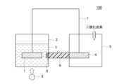
- FIG. 1 is a diagram showing a configuration example of a carbon dioxide reduction device according to a first embodiment.
- FIG. 2 is a diagram showing a configuration example of a water-repellent film.
- FIG. 3 is a diagram showing a first manufacturing method of the water-repellent film.
- FIG. 4 is a diagram showing a second manufacturing method of the water-repellent film.
- FIG. 5 is a diagram showing a third manufacturing method of the water-repellent film.
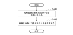
- FIG. 6 is a diagram showing a fourth manufacturing method of the water-repellent film.
- FIG. 7 is a diagram showing measurement results of the faradaic efficiency of formic acid according to the first embodiment.
- FIG. 8 is a diagram showing a configuration example of a carbon dioxide reduction device according to the second embodiment.
- FIG. 9 is a diagram showing measurement results of the faradaic efficiency of formic acid according to the second embodiment.
- FIG. 1 is a diagram showing a configuration example of a carbon dioxide reduction device 100 according to the first embodiment.
- the carbon dioxide reduction device 100 includes an oxidation electrode 1, an oxidation tank 2, an electrolytic solution 3, a reduction electrode 4, a reduction tank 5, an electrolyte membrane 6, a conducting wire 7, and a light source 8. and a water-repellent film 9.
- the oxidation electrode 1 is immersed in the electrolytic solution 3 in the oxidation bath 2 .
- the oxidation electrode 1 is formed by forming a semiconductor on a substrate having a predetermined area.
- the oxidation electrode 1 is formed, for example, by forming a film of a compound exhibiting photoactivity or redox activity, such as a nitride semiconductor, titanium oxide, amorphous silicon, ruthenium complex, or rhenium complex, on the surface of a sapphire substrate.
- the oxidation tank 2 holds an electrolytic solution 3 in which the oxidation electrode 1 is immersed.
- the electrolytic solution 3 is placed in the oxidation tank 2.
- the electrolytic solution 3 is, for example, an aqueous potassium hydrogen carbonate solution, an aqueous sodium hydrogen carbonate solution, an aqueous potassium chloride solution, an aqueous sodium chloride solution, an aqueous potassium hydroxide solution, an aqueous rubidium hydroxide solution, or an aqueous cesium hydroxide solution.
- the reduction electrode 4 is arranged inside the reduction tank 5 . Similar to the oxidation electrode 1, the reduction electrode 4 is formed on a substrate having a predetermined area.
- the reduction electrode 4 is, for example, a porous body of copper, platinum, gold, silver, indium, palladium, gallium, nickel, tin, cadmium, or alloys thereof.
- the reduction electrode 4 is composed of compounds such as silver oxide, copper oxide, copper (II) oxide, nickel oxide, indium oxide, tin oxide, tungsten oxide, tungsten (VI) oxide, copper oxide, metal ions and anionic coordination. It may be a porous metal complex having an element.
- the reduction tank 5 has a reduction electrode 4 inside and holds gaseous carbon dioxide supplied from the outside through a pipe.
- the electrolyte membrane 6 is arranged between the oxidation tank 2 and the reduction tank 5 . More precisely, the electrolyte membrane 6 is arranged between the electrolyte 3 and the reduction electrode 4 in contact with each other.
- the electrolyte membrane 6 is, for example, Nafion (registered trademark), Phorblue, or Aquibion, which are electrolyte membranes having a carbon-fluorine skeleton, or Selemion or Neosepta, which are electrolyte membranes having a hydrocarbon-based skeleton.
- the conducting wire 7 physically and electrically connects the oxidation electrode 1 and the reduction electrode 4 .
- the light source 8 is arranged close to the oxidation tank 2 .
- the light source 8 is, for example, sunlight, a xenon lamp, a pseudo-sunlight light source, a halogen lamp, a mercury lamp, or a light source combining these.
- the reduction electrode 4 and the electrolyte membrane 6 may be configured using a single material.
- it can be realized using a gas diffusion electrode (GDE®) composed of a porous material and a catalyst. Since the gas diffusion electrode can separate liquid and gas, and cations can move within the electrode, it has the same function as both of the reduction electrode 4 and the electrolyte membrane 6 .
- GDE® gas diffusion electrode
- the reduction electrode 4 and the electrolyte membrane 6 are each drawn so as to have a large width in the horizontal direction of the paper, but the width in the horizontal direction of the paper is reduced and the plane is formed in the depth direction of the paper. It may be in the shape of a thin plate that is flattened.
- the electrolyte 3 and the semiconductor oxidation electrode 1 immersed in the electrolyte 3 are used to emit light (light energy) from the light source 8 .
- An oxidation reaction of water takes place.
- a reduction reaction of carbon dioxide is carried out using a reduction electrode 4 connected to the oxidation electrode 1 via a lead wire 7 and carbon dioxide brought into direct contact with the reduction electrode 4 .
- a carbon dioxide reduction reaction is induced by protons, electrons, and gaseous carbon dioxide that is in direct contact with the reduction electrode 4 .
- This oxidation-reduction reaction produces carbon monoxide, formic acid, methane, and the like that can be used as energy resources.
- the electrolyte membrane 6 swells, and the electrolytic solution 3 flows into the pores of the electrolyte membrane 6. and oozes out onto the surface of the reduction electrode 4 in the reduction tank 5 .
- the surface of the electrolyte membrane 6 on the side of the oxidation tank 2 that comes into contact with the electrolytic solution 3 should be water repellent. must be transferred using the water in the electrolyte membrane 6 as a medium.
- a water-repellent film 9 is formed on a part of the surface of the electrolyte membrane 6 that contacts the electrolyte 3 so as not to cover the entire surface of the electrolyte membrane 6 .
- a plurality of water-repellent films 9 are formed on the surface at predetermined intervals.
- the water-repellent film 9 is formed not on the entire surface of the electrolyte membrane 6 but on a part of the surface, a state in which protons can pass through the electrolyte membrane 6 can be maintained. As a result, the reduction reaction of carbon dioxide can proceed, and a decrease in the efficiency of the reduction reaction can be suppressed.
- the water repellent treatment for manufacturing the water repellent film 9 includes a liquid phase method and a vapor phase method.
- the target object is immersed in a fluorine-based solvent in which a fluorine-based polymer, which is a water repellent, is dissolved by a dip coating method, etc., and then the target is heated to remove the solvent, thereby removing the fluorine-based This is a method of precipitating a polymer.
- a film is formed on the surface of the object with the above-mentioned fluorine-based solvent by a cast coating method, a spin coating method, or the like, and then the object is heated to remove the solvent.
- the object and the water-repellent fluorine-based low-molecular weight agent are placed in the same closed space, the fluorine-based low-molecular weight is heated to vaporize, and then the surface of the object is
- FIG. 3A and 3B are diagrams showing a first method for manufacturing the water-repellent film 9.
- the first manufacturing method is a method of manufacturing the water-repellent film 9 by a liquid phase method.
- Nafion was used for the electrolyte membrane 6 .
- OPTOOL DSX was used as the water repellent.
- first step S101 a water-soluble polymer is dissolved in pure water to create a polyvinyl alcohol aqueous solution with a concentration of 1%.
- second step S102 the polyvinyl alcohol aqueous solution is dropped onto one side of the Nafion film by spin coating to form a film of polyvinyl alcohol on the one side.
- the Nafion membrane is left in an oven at 60°C for 1 hour to evaporate the moisture in the polyvinyl alcohol (third step S103).
- a polymer membrane water-soluble polymer
- the Nafion membrane is dip-coated in an OPTOOL DSX solution (water-repellent polymer) for 1 minute and pulled up (fourth step S104).
- OPTOOL DSX solution water-repellent polymer
- the Nafion membrane is washed with pure water (fifth step S105).
- the polyvinyl alcohol (water-soluble polymer) coated with the water-repellent film can be removed. That is, the polymer film (water-soluble polymer) is removed from one side of the Nafion film, and the water-repellent film on the polymer film is also removed.
- a water-repellent film can be formed only on one side of the Nafion film.
- a relatively thick water-repellent film on the order of micrometers can be formed.
- FIG. 4A and 4B are diagrams showing a second manufacturing method of the water-repellent film 9.
- the second manufacturing method is a method of manufacturing the water-repellent film 9 by another liquid phase method. Nafion was used for the electrolyte membrane 6 . OPTOOL DSX was used as the water repellent.
- OPTOOL DSX water-repellent polymer
- a water-repellent film can be formed only on one side of the Nafion film.
- a spin coating method since centrifugal force is used, in principle, a thin water-repellent film on the order of submicrometers can be formed.
- FIG. 5 is a diagram showing a third manufacturing method for the water-repellent film 9.
- FIG. A third manufacturing method is a method for manufacturing the water-repellent film 9 by a vapor phase method. Nafion was used for the electrolyte membrane 6 .
- a fluorine-based silane coupling agent eg, heptadecafluoro-1,1,2,2-tetrahydrodecyltrimethoxysilane was used as the water repellent agent.
- a water-soluble polymer is dissolved in pure water to create a polyvinyl alcohol aqueous solution with a concentration of 1% (first step S301).
- the polyvinyl alcohol aqueous solution is dropped onto one side of the Nafion film by spin coating to form a film of polyvinyl alcohol on the one side (second step S302).
- the Nafion membrane is left in an oven at 60°C for 1 hour to evaporate the moisture in the polyvinyl alcohol (third step S303).
- a polymer membrane water-soluble polymer
- the Nafion film and the fluorine-based silane coupling agent water-repellent low molecular weight are placed in a Teflon container and sealed (fourth step S304).
- the Teflon container is placed in an oven and heated at 150°C (fifth step S305).
- This step evaporates the fluorine-containing silane coupling agent and forms water-repellent films on both sides of the Nafion film.
- the Nafion membrane is washed with pure water (sixth step S306).
- the polyvinyl alcohol (water-soluble polymer) coated with the water-repellent film can be removed. That is, the polymer film (water-soluble polymer) is removed from one side of the Nafion film, and the water-repellent film on the polymer film is also removed.
- a water-repellent film can be formed only on one side of the Nafion film.
- a monomolecular film is formed on the surface of Nafion, so an extremely thin water-repellent film on the order of nanometers can be formed.
- FIG. 6 is a diagram showing a fourth manufacturing method for the water-repellent film 9.
- the fourth manufacturing method is a method of manufacturing the water-repellent film 9 by another vapor phase method.
- Nafion was used for the electrolyte membrane 6 .
- a fluorine-based silane coupling agent eg, heptadecafluoro-1,1,2,2-tetrahydrodecyltrimethoxysilane was used as the water repellent agent.
- the Nafion membrane is brought into close contact with the bottom of a Teflon container and left to stand, and a fluorine-based silane coupling agent (water-repellent low-molecular-weight) is added and sealed (first step S401).
- a fluorine-based silane coupling agent water-repellent low-molecular-weight
- the Teflon container is placed in an oven and heated at 150° C. (second step S402). This step evaporates the fluorine-containing silane coupling agent and forms a water-repellent film on one side of the Nafion film.
- a water-repellent film can be formed only on one side of the Nafion film.
- a monomolecular film is formed on the surface of Nafion, so an extremely thin water-repellent film on the order of nanometers can be formed.
- GaN gallium nitride
- AlGaN aluminum gallium nitride
- a promoter thin film of nickel oxide (NiO) was formed. The promoter thin film was used as the oxidation electrode 1 , and the oxidation electrode 1 was immersed in the electrolytic solution 3 of 1.0 mol/L potassium hydroxide aqueous solution in the oxidation tank 2 .
- a reduction electrode 4 was formed using a copper porous body, the reduction electrode 4 was connected to the oxidation electrode 1 with a lead wire 7 , and the reduction electrode 4 was installed in the reduction tank 5 .
- Nafion was used for the electrolyte membrane 6 that physically separates the oxidation tank 2 and the reduction tank 5 .
- one surface on which the water-repellent film 9 is formed is arranged so as to be in contact with the electrolytic solution 3 in the oxidation tank 2, and the other surface is in contact with the reduction electrode 4 in the reduction tank 5. arranged to do so.
- a 300 W xenon lamp was used as the light source 8 . Wavelengths of 450 nm or more were cut with a filter, and the illuminance was set to 6.6 mW/cm 2 . The irradiation surface of the oxidation electrode 1 was set to 2.5 cm 2 .
- nitrogen and carbon dioxide were supplied to the oxidation tank 2 and the reduction tank 5 at a flow rate of 5 ml/min and a pressure of 0.5 MPa, respectively. Nitrogen was bubbled into the oxidation tank 2 for the purpose of analyzing reaction products. The insides of the oxidation tank 2 and the reduction tank 5 were sufficiently replaced with nitrogen and carbon dioxide, respectively, and light was irradiated from the light source 8 . After that, the reduction reaction of carbon dioxide progressed on the surface of the copper porous body, which was the reduction electrode 4 .
- the current flowing between the oxidation electrode 1 and the reduction electrode 4 due to the irradiated light was measured with an electrochemical measurement device (1287 type potentiogalvanostat manufactured by Solartron). Further, gas and liquid generated in the oxidation tank 2 and the reduction tank 5 were sampled, and reaction products were analyzed using a gas chromatograph, a liquid chromatograph, and a gas chromatograph-mass spectrometer.
- the effect of the water-repellent film 9 formed on the surface of the electrolyte film 6 was examined by obtaining the Faradaic efficiency of the carbon dioxide reduction reaction.
- a method for calculating the Faraday efficiency of the carbon dioxide reduction reaction will be described later.
- Example 1 Nafion was used as the electrolyte membrane 6
- OPTOOL DSX was used as the water repellent
- a 1% polyvinyl alcohol aqueous solution dissolved in pure water was used as the water-soluble polymer.
- the manufactured water-repellent film 9 was used.
- Example 2 Nafion was used as the electrolyte film 6
- OPTOOL DSX was used as the water repellent
- the water repellent film 9 manufactured by the manufacturing method 2 was used.
- Example 3 Nafion was used as the electrolyte membrane 6, heptadecafluoro-1,1,2,2-tetrahydrodecyltrimethoxysilane was used as the water repellent, and pure water was used as the water-soluble polymer.
- a water-repellent film 9 manufactured by manufacturing method 3 using a polyvinyl alcohol aqueous solution having a concentration of 1% was used.
- Example 4 Nafion was used as the electrolyte film 6, and heptadecafluoro-1,1,2,2-tetrahydrodecyltrimethoxysilane was used as the water repellent, and the water repellent film 9 was manufactured by the manufacturing method 4. was used.
- FIG. 7 is a diagram showing the measurement results of the Faraday efficiency of formic acid according to the first embodiment.
- the Faraday efficiency decreased after 6 hours.
- the Faraday efficiency did not decrease even after 6 hours. This is because, as a result of introducing the water-repellent film 9 into the Nafion film, leakage of the electrolytic solution 3 to the reduction electrode 4 is suppressed, and the reaction sites of the reduction electrode 4 are not filled with the electrolytic solution 3 .
- the coverage of the water-repellent film 9 on the Nafion film was estimated using the Cassie-Baxter formula.
- the contact angle of the Nafion film coated with the water-repellent film 9 is ⁇
- the contact angle of the Nafion film surface is ⁇ 1
- the ratio of the Nafion film surface is f1
- the contact angle of the surface of the water-repellent film 9 is ⁇ 2
- the ratio of the surface of the water-repellent film 9 is f2
- the Faraday efficiency of carbon dioxide indicates the ratio of the number of electrons used in the carbon dioxide reduction reaction to the number of electrons transferred between the oxidation electrode 1 and the reduction electrode 4 by light irradiation or current/voltage application. , can be calculated by equation (2).
- A is the concentration (ppm) of the reduction reaction product.
- B is the flow rate (L/sec) of the carrier gas.
- Z is the number of electrons required for the reduction reaction.
- F is the Faraday constant (C/mol).
- T is the light irradiation time or the current/voltage application time (sec).
- V g is the molar volume of gas (L/mol).
- C C x V l x Z x F (4)
- C concentration (mol/L) of the reduction reaction product.
- V l is the volume (L) of the liquid sample.
- Z is the number of electrons required for the reduction reaction.
- F is the Faraday constant (C/mol).
- the first embodiment has been described above. According to the carbon dioxide reduction device 100 according to the first embodiment, it is possible to provide the carbon dioxide reduction device 100 that allows the carbon dioxide reduction reaction to proceed without reducing the Faraday efficiency.
- the oxidation tank 2 performs the oxidation reaction of water by the irradiation light from the light source 8 using the electrolytic solution 3 and the semiconductor oxidation electrode 1 immersed in the electrolytic solution 3, and the oxidation electrode 1 is provided with a lead wire.
- the electrolyte membrane 6 has a water-repellent film 9 on a part of the surface that contacts the electrolyte 3.
- the water repellency of the water-repellent film 9 provided on the surface of the electrolytic solution 3 can suppress the electrolytic solution 3 in the oxidation tank 2 from penetrating into the electrolyte film 6, and the electrolytic solution 3 can be prevented from flowing into the reduction electrode 4. Leakage can be suppressed, and the reaction site of the reduction electrode 4 is not filled with the electrolyte 3. Moreover, since the water-repellent film 9 is provided on a part of the surface of the electrolyte membrane 6 , a state in which protons can pass through the electrolyte membrane 6 can be maintained. As a result, the reduction reaction of carbon dioxide can proceed, and a decrease in the efficiency of the reduction reaction can be suppressed.
- FIG. 8 is a diagram showing a configuration example of the carbon dioxide reduction device 100 according to the second embodiment.
- the oxidation electrode 1 is platinum.
- the oxidation electrode 1 may be gold or silver, for example.
- An external power supply 10 is an electrochemical measurement device, and is connected in series to the conductor 7 connecting the oxidation electrode 1 and the reduction electrode 4 .
- Power supply 10 may be any other power supply.
- Other components are the same as in the first embodiment.
- the current and voltage (electrical energy) from the power source 10 are generated using the electrolytic solution 3 and the platinum (metal) oxidation electrode 1 immersed in the electrolytic solution 3. Oxidation reaction of the water in the electrolytic solution 3 is performed by .
- a reduction reaction of carbon dioxide is carried out using the reduction electrode 4 connected to the power source 10 (source of electrical energy) and the carbon dioxide brought into direct contact with the reduction electrode 4 .
- a water-repellent film 9 is provided on a portion of the surface of the electrolyte membrane 6 that contacts the electrolytic solution 3 so as not to cover the entire surface of the electrolyte membrane 6 .
- a plurality of water-repellent films 9 are formed on the surface at predetermined intervals.
- the manufacturing method of the water-repellent film 9 the first manufacturing method to the fourth manufacturing method are used as in the first embodiment.
- FIG. 9 is a diagram showing the measurement results of the Faraday efficiency of formic acid according to the second embodiment.
- Examples 5 to 8 are examples using the same electrolyte membrane 6 as in Examples 1 to 4 described in the first embodiment.
- a comparative example in which Nafion without the water-repellent film 9 is used as the electrolyte film 6 is also described.
- the second embodiment has been described above. According to the carbon dioxide reduction device 100 according to the second embodiment, it is possible to provide the carbon dioxide reduction device 100 that allows the carbon dioxide reduction reaction to proceed without reducing the Faraday efficiency.
- an oxidation tank 2 that performs an oxidation reaction of water by current and voltage from a power supply 10 using an electrolytic solution 3 and a platinum (metal) oxidation electrode 1 immersed in the electrolytic solution 3, and a power supply 10 a reduction tank 5 for performing a reduction reaction of carbon dioxide using a reduction electrode 4 connected to the reduction electrode 4 and carbon dioxide brought into direct contact with the reduction electrode 4; an electrolytic solution 3 in the oxidation tank 2;
- the carbon dioxide reduction device 100 including an electrolyte membrane 6 disposed in contact with each of the electrolyte membrane 6 , the electrolyte membrane 6 has a water-repellent film 9 on a portion of the surface that contacts the electrolytic solution 3 .
- the water repellency of the water-repellent film 9 provided on the surface of the electrolytic solution 3 can suppress the electrolytic solution 3 in the oxidation tank 2 from penetrating into the electrolyte film 6, and the electrolytic solution 3 can be prevented from flowing into the reduction electrode 4. Leakage can be suppressed, and the reaction site of the reduction electrode 4 is not filled with the electrolyte 3. Moreover, since the water-repellent film 9 is provided on a part of the surface of the electrolyte membrane 6 , a state in which protons can pass through the electrolyte membrane 6 can be maintained. As a result, the reduction reaction of carbon dioxide can proceed, and a decrease in the efficiency of the reduction reaction can be suppressed.
- the present invention can be widely used in fields related to carbon dioxide recycling. Although light energy is used in the first embodiment and electrical energy is used in the second embodiment, other renewable energy may be used. It is also possible to combine the first embodiment and the second embodiment.
- the electrolytic solution 3 in the oxidation tank 2 and the reduction electrode 4 in the reduction tank 5 are arranged in contact with each other, and carbon dioxide is brought into direct contact with the reduction electrode 4 to cause a reduction reaction of carbon dioxide.
- Any electrolyte membrane can be applied as long as it is the electrolyte membrane 6 used in the carbon dioxide reduction apparatus 100 that performs the above.
- oxidation electrode 2 oxidation tank 3: electrolytic solution 4: reduction electrode 5: reduction tank 6: electrolyte membrane 7: conducting wire 8: light source 9: water-repellent film 10: power supply 100: carbon dioxide reduction device
Landscapes
- Chemical & Material Sciences (AREA)
- Organic Chemistry (AREA)
- Engineering & Computer Science (AREA)
- Chemical Kinetics & Catalysis (AREA)
- Electrochemistry (AREA)
- Materials Engineering (AREA)
- Metallurgy (AREA)
- Inorganic Chemistry (AREA)
- Electrolytic Production Of Non-Metals, Compounds, Apparatuses Therefor (AREA)
Priority Applications (3)
| Application Number | Priority Date | Filing Date | Title |
|---|---|---|---|
| PCT/JP2021/041514 WO2023084682A1 (ja) | 2021-11-11 | 2021-11-11 | 電解質膜、及び、電解質膜の製造方法 |
| US18/699,379 US20240410068A1 (en) | 2021-11-11 | 2021-11-11 | Electrolyte Membrane and Manufacturing Method of Electrolyte Membrane |
| JP2023559297A JP7783508B2 (ja) | 2021-11-11 | 2021-11-11 | 電解質膜の製造方法 |
Applications Claiming Priority (1)
| Application Number | Priority Date | Filing Date | Title |
|---|---|---|---|
| PCT/JP2021/041514 WO2023084682A1 (ja) | 2021-11-11 | 2021-11-11 | 電解質膜、及び、電解質膜の製造方法 |
Publications (1)
| Publication Number | Publication Date |
|---|---|
| WO2023084682A1 true WO2023084682A1 (ja) | 2023-05-19 |
Family
ID=86335384
Family Applications (1)
| Application Number | Title | Priority Date | Filing Date |
|---|---|---|---|
| PCT/JP2021/041514 Ceased WO2023084682A1 (ja) | 2021-11-11 | 2021-11-11 | 電解質膜、及び、電解質膜の製造方法 |
Country Status (3)
| Country | Link |
|---|---|
| US (1) | US20240410068A1 (https=) |
| JP (1) | JP7783508B2 (https=) |
| WO (1) | WO2023084682A1 (https=) |
Citations (5)
| Publication number | Priority date | Publication date | Assignee | Title |
|---|---|---|---|---|
| JP2018090838A (ja) * | 2016-11-30 | 2018-06-14 | 昭和シェル石油株式会社 | 二酸化炭素還元装置 |
| JP2018153173A (ja) * | 2017-03-16 | 2018-10-04 | 株式会社東芝 | 二酸化炭素固定化装置及び燃料生産システム |
| WO2020121556A1 (ja) * | 2018-12-10 | 2020-06-18 | 日本電信電話株式会社 | 二酸化炭素の気相還元装置及び二酸化炭素の気相還元方法 |
| JP2021059760A (ja) * | 2019-10-08 | 2021-04-15 | 株式会社豊田中央研究所 | Co2還元反応装置 |
| WO2021117164A1 (ja) * | 2019-12-11 | 2021-06-17 | 日本電信電話株式会社 | 二酸化炭素の気相還元装置、および、二酸化炭素の気相還元方法 |
Family Cites Families (2)
| Publication number | Priority date | Publication date | Assignee | Title |
|---|---|---|---|---|
| DE102017211930A1 (de) | 2017-07-12 | 2019-01-17 | Siemens Aktiengesellschaft | Membran gekoppelte Kathode zur Reduktion von Kohlendioxid in säurebasierten Elektrolyten ohne mobile Kationen |
| US20240229256A9 (en) * | 2019-10-25 | 2024-07-11 | Siemens Energy Global GmbH & Co. KG | Electrolyser device and method for carbon dioxide reduction |
-
2021
- 2021-11-11 JP JP2023559297A patent/JP7783508B2/ja active Active
- 2021-11-11 WO PCT/JP2021/041514 patent/WO2023084682A1/ja not_active Ceased
- 2021-11-11 US US18/699,379 patent/US20240410068A1/en active Pending
Patent Citations (5)
| Publication number | Priority date | Publication date | Assignee | Title |
|---|---|---|---|---|
| JP2018090838A (ja) * | 2016-11-30 | 2018-06-14 | 昭和シェル石油株式会社 | 二酸化炭素還元装置 |
| JP2018153173A (ja) * | 2017-03-16 | 2018-10-04 | 株式会社東芝 | 二酸化炭素固定化装置及び燃料生産システム |
| WO2020121556A1 (ja) * | 2018-12-10 | 2020-06-18 | 日本電信電話株式会社 | 二酸化炭素の気相還元装置及び二酸化炭素の気相還元方法 |
| JP2021059760A (ja) * | 2019-10-08 | 2021-04-15 | 株式会社豊田中央研究所 | Co2還元反応装置 |
| WO2021117164A1 (ja) * | 2019-12-11 | 2021-06-17 | 日本電信電話株式会社 | 二酸化炭素の気相還元装置、および、二酸化炭素の気相還元方法 |
Also Published As
| Publication number | Publication date |
|---|---|
| JPWO2023084682A1 (https=) | 2023-05-19 |
| JP7783508B2 (ja) | 2025-12-10 |
| US20240410068A1 (en) | 2024-12-12 |
Similar Documents
| Publication | Publication Date | Title |
|---|---|---|
| Schreier et al. | Solar conversion of CO2 to CO using Earth-abundant electrocatalysts prepared by atomic layer modification of CuO | |
| US10196748B2 (en) | Reduction catalyst and chemical reactor | |
| Zhong et al. | Surface modification of CoO x loaded BiVO4 photoanodes with ultrathin p-type NiO layers for improved solar water oxidation | |
| Yang et al. | Improving hematite-based photoelectrochemical water splitting with ultrathin TiO2 by atomic layer deposition | |
| Zhu et al. | Nanostructured tungsten trioxide thin films synthesized for photoelectrocatalytic water oxidation: a review | |
| Mei et al. | Protection of p+-n-Si photoanodes by sputter-deposited Ir/IrO x thin films | |
| JP7121318B2 (ja) | 二酸化炭素の気相還元装置及び二酸化炭素の気相還元方法 | |
| JP5753641B2 (ja) | 二酸化炭素還元装置および二酸化炭素を還元する方法 | |
| Ostojic et al. | Electrocatalytic study of the oxygen reduction reaction at gold nanoparticles in the absence and presence of interactions with SnO x supports | |
| US10829861B2 (en) | Reduction catalyst, and chemical reactor, reduction method and reduction product-producing system employing the catalyst | |
| WO2012046374A1 (ja) | 二酸化炭素を還元する方法 | |
| Kronawitter et al. | Observation of surface-bound negatively charged hydride and hydroxide on GaP (110) in H2O environments | |
| Fabre et al. | Silicon photoelectrodes prepared by low-cost wet methods for solar photoelectrocatalysis | |
| Yuan et al. | Inorganic core–shell assemblies for closing the artificial photosynthetic cycle | |
| Zafeiropoulos et al. | Solar hydrogen generation from ambient humidity using functionalized porous photoanodes | |
| US10550488B2 (en) | Reduction catalyst, reduction reactor and reduction method | |
| Gurudayal et al. | Revealing the influence of doping and surface treatment on the surface carrier dynamics in hematite nanorod photoanodes | |
| WO2015133127A1 (ja) | 二酸化炭素還元電極及びこれを用いた二酸化炭素還元装置 | |
| WO2015136776A1 (ja) | 酸化電極および光電気化学装置 | |
| He et al. | Dependence of interface energetics and kinetics on catalyst loading in a photoelectrochemical system | |
| JP7801637B2 (ja) | 還元電極の製造方法 | |
| JP2017101285A (ja) | 還元反応用電極及びそれを用いた反応デバイス | |
| JP7783508B2 (ja) | 電解質膜の製造方法 | |
| Chen et al. | Porous carbon nanorods encapsulating bismuth nanoparticles promote p-Si nanowire array for photoelectrocatalytic CO2 reduction to formate | |
| WO2024116355A1 (ja) | 二酸化炭素還元装置 |
Legal Events
| Date | Code | Title | Description |
|---|---|---|---|
| 121 | Ep: the epo has been informed by wipo that ep was designated in this application |
Ref document number: 21964037 Country of ref document: EP Kind code of ref document: A1 |
|
| ENP | Entry into the national phase |
Ref document number: 2023559297 Country of ref document: JP Kind code of ref document: A |
|
| WWE | Wipo information: entry into national phase |
Ref document number: 18699379 Country of ref document: US |
|
| 122 | Ep: pct application non-entry in european phase |
Ref document number: 21964037 Country of ref document: EP Kind code of ref document: A1 |