WO2023084581A1 - 電子制御装置及び車両制御システム - Google Patents
電子制御装置及び車両制御システム Download PDFInfo
- Publication number
- WO2023084581A1 WO2023084581A1 PCT/JP2021/041130 JP2021041130W WO2023084581A1 WO 2023084581 A1 WO2023084581 A1 WO 2023084581A1 JP 2021041130 W JP2021041130 W JP 2021041130W WO 2023084581 A1 WO2023084581 A1 WO 2023084581A1
- Authority
- WO
- WIPO (PCT)
- Prior art keywords
- vehicle
- priority
- state
- information
- sensor
- Prior art date
- Legal status (The legal status is an assumption and is not a legal conclusion. Google has not performed a legal analysis and makes no representation as to the accuracy of the status listed.)
- Ceased
Links
Images


Classifications
-
- B—PERFORMING OPERATIONS; TRANSPORTING
- B60—VEHICLES IN GENERAL
- B60W—CONJOINT CONTROL OF VEHICLE SUB-UNITS OF DIFFERENT TYPE OR DIFFERENT FUNCTION; CONTROL SYSTEMS SPECIALLY ADAPTED FOR HYBRID VEHICLES; ROAD VEHICLE DRIVE CONTROL SYSTEMS FOR PURPOSES NOT RELATED TO THE CONTROL OF A PARTICULAR SUB-UNIT
- B60W50/00—Details of control systems for road vehicle drive control not related to the control of a particular sub-unit, e.g. process diagnostic or vehicle driver interfaces
- B60W50/06—Improving the dynamic response of the control system, e.g. improving the speed of regulation or avoiding hunting or overshoot
Definitions
- the present invention relates to electronic control units and vehicle control systems.
- Zone Architecture In recent years, in order to reduce costs, a method called Zone Architecture has been developed, in which a ZoneECU (Electronic Control Unit), which is an example of an area electronic device, is placed in each area of the vehicle, and information from the ZoneECU is aggregated into an integrated ECU. progressing. As the level of the automated driving system improves, the number of sensors connected to ZoneECU increases. Various types of information are transmitted from the ZoneECU to the integrated ECU according to priority. For example, the control information is set to "high" in priority and transmitted with the highest priority. On the other hand, the sensor information has a priority of "middle", and the entertainment information has a priority of "low”. That is, the ZoneECU sends the control information, the sensor information, and the entertainment information in this order to the integrated ECU. By the way, it was necessary to change the priority of data transfer depending on the state of the vehicle.
- a ZoneECU Electronic Control Unit
- Patent Document 1 has been known as a method for setting the priority of various types of information.
- this patent document 1 "When performing automatic driving control, it is possible to set a high priority to data from an external device located in an important peripheral area where it is necessary to confirm whether or not an object exists. You can.”
- Patent Document 1 sets the priority of data obtained from an external communication device. With this method, it was not possible to set the priority of the sensor to be acquired depending on the state of the vehicle (for example, turning left).
- the present invention has been made in view of such circumstances, and an object of the present invention is to change the priority of area electronic devices according to changes in vehicle conditions.
- the electronic control device controls the vehicle based on one or more pieces of information obtained from a plurality of area electronic devices provided for each area of the vehicle.
- This electronic control unit is provided for each of a plurality of area electronic devices, and includes a first priority information table in which the priority of the area electronic device that acquires information is set, and a table that changes the state of the vehicle according to the external conditions of the vehicle. If so, the first priority information table is referred to determine the area electronic device whose priority is to be changed according to the changing vehicle state, and the determined area electronic device is instructed to change the priority. and a control unit for obtaining changed information with a higher priority from the area electronic device that instructed to change the priority.
- the priorities of the area electronic devices are changed according to changes in the state of the vehicle, it is possible to preferentially obtain information from the area electronic devices with higher priority.
- FIG. 1 is a block diagram showing an example of the overall configuration of a vehicle control system according to a first embodiment of the invention
- FIG. 1 is a schematic diagram showing an arrangement example of a sensor, a ZoneECU, and an integrated ECU in a vehicle according to a first embodiment of the present invention
- FIG. It is a figure which shows the example which looked at the situation which the vehicle which concerns on the 1st Embodiment of this invention is turning left from the top.
- 1 is a functional configuration diagram of a vehicle control system according to a first embodiment of the invention
- FIG. FIG. 4 is a table configuration diagram of a current priority information table provided for each ZoneECU according to the first embodiment of the present invention
- FIG. 4 is a table configuration diagram of a priority information table in a driving pattern according to the first embodiment of the present invention
- FIG. 4 is a table configuration diagram of a priority information table in ZoneECU according to the first embodiment of the present invention
- FIG. 4 is a flowchart showing an example of processing on the ZoneECU side according to the first embodiment of the present invention
- 4 is a flowchart showing an example of processing on the integrated ECU side according to the first embodiment of the present invention
- FIG. 2 is a block diagram showing an example of the overall configuration of a vehicle control system according to a second embodiment of the invention
- FIG. FIG. 7 is a diagram showing recognition ranges of sensors mounted on a vehicle according to a second embodiment of the present invention
- FIG. 9 is a table configuration diagram of an ECU priority information table in a sensor failure state according to the second embodiment of the present invention
- FIG. 2 is a functional configuration diagram of a vehicle control system according to a second embodiment of the invention
- FIG. FIG. 9 is a flowchart showing an example of processing on the side of an integrated ECU according to the second embodiment of the present invention
- FIG. 11 is a table configuration diagram of a priority information table in a driving pattern according to a modification of the first and second embodiments of the present invention
- FIG. FIG. 10 is a top view of a vehicle according to a modification of the first and second embodiments of the present invention, which makes a left turn at an intersection;
- the processor may perform the entire processing described below.
- the processing described with the program as the subject of operation may be processing performed by a device including a processor. It may also include a dedicated hardware circuit that performs part or all of the processing performed by the processor.
- a computer program may be installed on the device from a program source.
- the program source may be, for example, a program distribution server or a computer-readable non-transitory recording medium.
- FIG. 1 is a block diagram showing an example of the overall configuration of a vehicle control system according to the first embodiment.
- the vehicle control system 1000A is an example of a control system that is installed in a vehicle 600 (see FIG. 2 described later) such as an automobile and that controls the operation of the vehicle 600 .
- the vehicle control system 1000A includes various sensors 13A (13B, 13C, 13D, 14A), entertainment information devices 16A (16B, 16C, 16D), various actuators 17A (17B, 17C, 17D), and a vehicle 600. and a ZoneECU 10A (10B, 10C, 10D) that controls each area such as the direction (for example, left front, left rear, right front, right rear).
- the vehicle control system 1000A also includes an integrated ECU 20 that collects data from the ZoneECUs 10A (10B, 10C, and 10D), recognizes an object outside the vehicle, recognizes the object, determines the operation of the vehicle, and controls the running of the vehicle. .
- This electronic control unit integrated ECU 20 controls the vehicle (vehicle 600) based on one or more pieces of information acquired from a plurality of area electronic devices (ZoneECUs 1 to 4) provided for each area of the vehicle (vehicle 600). can be controlled.
- the entertainment information equipment 16A (16B, 16C, 16D) is abbreviated as "ENT system”.
- ENT system As entertainment information transmitted from the entertainment information device 16A (16B, 16C, 16D) to the ZoneECU 10A (10B, 10C, 10D), for example, the current position of the vehicle 600 obtained from a car navigation system (not shown) installed in the vehicle 600. There is information indicating
- sensors 13A, 14A, 13B, 13C, and 13D are called sensors 1, 2, 3, 4, and 5 or sensors 1-5, respectively.
- Sensors 1 to 5 are used to acquire information of the surrounding environment of vehicle 600 such as Radar (Radio Detection and Ranging), LiDAR (Light/Laser Imaging Detection and Ranging), and cameras.
- Sensors 1-5 output information that each sensor can acquire to one of ZoneECUs 1-4 to which the sensors are connected.
- ZoneECUs 10A (10B, 10C, 10D) are referred to as ZoneECUs 1, 2, 3, 4 or ZoneECUs 1 to 4, respectively.
- ZoneECUs 1 to 4 when the ZoneECUs 1 to 4 are not distinguished, they may be called only by "ZoneECU".
- a ZoneECU is used as an example of an area electronic device. ZoneECUs 1 to 4 are arranged in areas (directions) within the vehicle. The sensors placed in the ZoneECUs 1 to 4 are placed in optimal locations so that they can recognize their respective areas (directions).
- Sensors 1 to 5 entertainment information equipment 16A (16B, 16C, 16D), various actuators 17A (17B, 17C, 17D), ZoneECUs 1 to 4, and integrated ECU 20 are connected to an in-vehicle network 30A (30B, 30C, 30D) and an in-vehicle network 40A (40B, 40C, 40D).
- the in-vehicle network 30A (30B, 30C, 30D) and the in-vehicle network 40A (40B, 40C, 40D) are composed of arbitrary communication networks such as Ethernet (registered trademark) and CAN-FD (CAN with Flexible Data-Rate). be done.
- Ethernet registered trademark
- CAN-FD CAN with Flexible Data-Rate
- ZoneECUs 1-4 each include a CPU 55A (55B, 55C, 55D) and a memory 50A (50B, 50C, 50D).
- the CPU 55A (55B, 55C, 55D) reads a program stored in the memory 50A (50B, 50C, 50D) and executes each process according to this program.
- the memory 50A (50B, 50C, 50D) is composed of, for example, RAM (Random Access Memory) and ROM (Read Only Memory).
- the memory 50A (50B, 50C, 50D) stores a ZoneECU-side processing program 11A (11B, 11C, 11D) executed by the CPU 55A (55B, 55C, 55D) and information necessary for ZoneECU processing.
- the information necessary for ZoneECU processing is, for example, a priority information table 12A (12B, 12C, 12D) that the ZoneECUs 1 to 4 refer to when transmitting data to the integrated ECU 20, and the like.
- a detailed configuration example of the priority information table 12A (12B, 12C, 12D) will be described later with reference to FIG.
- the CPU 55A (55B, 55C, 55D) of the ZoneECU executes the ZoneECU-side processing program 11A (11B, 11C, 11D) read out from the memory 50A (50B, 50C, 50D), thereby executing the priority setting unit 15A (15B). , 15C, 15D).
- the priority setting unit 15A (15B, 15C, 15D) changes the priority of the priority information table 12A (12B, 12C, 12D) based on the priority setting information input from the integrated ECU 20.
- the integrated ECU 20 includes a CPU 70 and a memory 60.
- CPU 70 executes each process according to a program stored in memory 60 .
- the CPU 70 is used as an example of a control section according to the present embodiment.
- the control unit determines that the state of the vehicle (vehicle 600) changes from the external conditions of the vehicle (vehicle 600)
- the control unit refers to the first priority information table (priority information table 22 in driving pattern), determining the area electronic devices (ZoneECUs 1 to 4) whose priorities are to be changed according to the changing state of the vehicle (vehicle 600), instructing the determined area electronic devices (ZoneECUs 1 to 4) to change the priority;
- the changed information with higher priority is obtained from the area electronic devices (ZoneECUs 1 to 4) that instructed to change the priority.
- the memory 60 is composed of, for example, a RAM and a ROM, and stores the processing program 21 on the integrated ECU side executed by the CPU 70 and information necessary for the processing of the integrated ECU 20 .
- the necessary information of the integrated ECU 20 is, for example, information stored in the priority information table 22 of ZoneECUs 1-4 in the running pattern of the vehicle 600 and the priority information table 23 of each ZoneECU 1-4.
- the first priority information table (priority information table 22 in driving pattern) is provided for each of a plurality of area electronic devices (ZoneECUs 1 to 4). degree is set.
- the second priority information table (priority information table 23 in each ZoneECU) stores the state of the vehicle (vehicle 600) and the area electronic device ( Defines the relationship with the priority of information transmitted by ZoneECUs 1 to 4).
- a vehicle state determination unit (vehicle state determination unit 71) of the control unit (CPU 70) determines a change in the state of the vehicle (vehicle 600) based on the external situation, and determines whether the state of the vehicle (vehicle 600) changes.
- the priority defined in the second priority information table (priority information table 23 in each ZoneECU) is the second priority information table (priority information in each ZoneECU) after the state of the vehicle (vehicle 600) changes.
- the vehicle state determination unit 71 can determine the state of the vehicle 600 as the vehicle state based on various data acquired from the ZoneECUs 1 to 4, and can recognize the running pattern of the vehicle 600.
- Various entertainment-related information devices 16A (16B, 16C, 16D) are information devices that are not necessary for running control of the vehicle 600, such as navigation information and music information.
- the various actuators 17A (17B, 17C, 17D) include one or more actuators that control the operation of corresponding devices in response to accelerator, brake, steering, etc. (not shown) operated by the driver of the vehicle 600.
- Various actuators 17 ⁇ /b>A 17 ⁇ /b>B, 17 ⁇ /b>C, 17 ⁇ /b>D
- control the operation of equipment related to running mounted on vehicle 600 based on control information input from integrated ECU 20 .
- the various actuators 17A (17B, 17C, 17D) notify the integrated ECU 20 of vehicle control information indicating the current control state of the vehicle 600.
- the integrated ECU 20 Based on the vehicle control information notified from the actuators 17A (17B, 17C, 17D), the integrated ECU 20 instructs the various actuators 17A (17B, 17C, 17D) with control information such as acceleration/deceleration and steering fine adjustment. Is possible.
- the program may be described as an operating subject for convenience, but the actual executing subject is the CPU 55A (55B, 55C, 55D, 70) that executes the program.
- the integrated ECU 20 can also have an arithmetic element capable of various types of information processing, such as an FPGA (Field-Programmable Gate Array).
- the integrated ECU 20 can also have a magnetic storage medium such as a HDD (Hard Disk Drive) or a semiconductor storage medium such as an SSD (Solid State Drive) other than the RAM and ROM as the memory 60 .
- Various programs, parameters, etc. may be stored in these magnetic storage media and semiconductor storage media.
- FIG. 2 is a schematic diagram showing an arrangement example of sensors 1 to 5, ZoneECUs 1 to 4, and integrated ECU 20 in vehicle 600 according to the first embodiment.
- the placement positions of the sensors include any one of the front right, front left, rear right, and rear left of the vehicle (vehicle 600).
- a sensor 1 is installed in the front center of the vehicle 600
- a sensor 2 is installed in the front left
- a sensor 3 is installed in the rear left
- a sensor 4 is installed in the front right
- a sensor 4 is installed in the rear right. 5 is installed.
- Vehicle 600 is divided into at least four areas. For example, the front left, rear left, front right, and rear right of the vehicle 600 are divided as areas. ZoneECUs 1 to 4 are provided for each area.
- a plurality of area electronic devices are arranged in the vicinity of the arrangement positions of the sensors (sensors 1 to 5) arranged on the vehicle (vehicle 600).
- sensors 1 and 2 are connected to ZoneECU 1 provided on the front left of vehicle 600 .
- Sensor 3 is connected to ZoneECU 4 provided on the rear left of vehicle 600 .
- Sensor 4 is connected to ZoneECU 2 provided on the front right of vehicle 600 .
- Sensor 5 is connected to ZoneECU 3 provided on the rear right of vehicle 600 .
- ZoneECUs 1 to 4 are connected to an integrated ECU 20 arranged near the center of vehicle 600 .
- FIG. 3 is a top view showing an example of a situation in which vehicle 600 is turning left. Here, an example of a travel pattern when vehicle 600 makes a left turn at intersection 700 is shown.
- the running pattern of vehicle 600 is defined in advance. Then, the priority of the ZoneECU changes according to the driving pattern. For example, in a driving pattern in which vehicle 600 makes a left turn, ZoneECUs 1 and 4 (see FIG. 2) arranged in the area on the left side of vehicle 600 have a higher priority than other ZoneECUs 2 and 3 . Therefore, the integrated ECU 20 preferentially acquires information from the ZoneECUs 1 and 4 and executes processing based on this information.
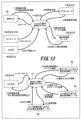
- FIG. 4 is a functional configuration diagram of the vehicle control system 1000A according to the first embodiment.
- FIG. 4 shows a configuration example of each function of the vehicle control system 1000A in the form of a data flow diagram. This FIG. 4 is described in a form called a state transition diagram or a state machine diagram, and briefly shows the flow of information in each part and program of the vehicle control system 1000A.
- the vehicle state determination unit (vehicle state determination unit 71) determines the state of the vehicle (vehicle 600) and the state transition of the vehicle (vehicle 600) based on a state machine that determines the state of the vehicle (vehicle 600) from the external situation. determine the state of
- the vehicle control system 1000A includes a priority information table 12A (12B, 12C, 12D) on the ZoneECU side and priority information tables 22 and 23 on the integrated ECU side.
- the respective processing programs executed by the ZoneECUs 1 to 4 and the integrated ECU 20 are executed by the CPU 55A (55B, 55C, 55D, 70) to perform the respective functions according to the present embodiment. is realized. First, an example of processing of ZoneECUs 1 to 4 shown on the upper side of FIG. 4 will be described.
- the processing program 11A (11B, 11C, 11D) on the ZoneECU side is executed by the CPU 55A (55B, 55C, 55D) on the ZoneECU side in the following procedures (1) to (8).
- procedures (1) to (8) do not necessarily have to be executed in order, and any one of the procedures may be executed in parallel or in reverse order.
- the processing program 11A (11B, 11C, 11D) on the ZoneECU side receives a control command value or priority setting information from the integrated ECU 20, it controls each section.
- the information received from the integrated ECU 20 may be at least one of the control command value of the vehicle 600 and the priority setting information.
- the processing program 11A (11B, 11C, 11D) on the ZoneECU side returns data corresponding to the information received from the integrated ECU 20 to the integrated ECU 20.
- This data includes vehicle control information received by the processing program 11A (11B, 11C, 11D) on the ZoneECU side from the actuator 17A (17B, 17C, 17D), priority information table 12A (12B, 12C) shown in FIG. , 12D), information detected by sensors 1 to 5 (described as "sensor input” in the figure), entertainment information received from entertainment information equipment 16A (16B, 16C, 16D) includes any of
- the processing program 11A (11B, 11C, 11D) on the ZoneECU side outputs the control command value input from the integrated ECU 20 to the actuator 17A (17B, 17C, 17D).
- the actuator 17A (17B, 17C, 17D) outputs the vehicle control information to the processing program 11A (11B, 11C, 11D) on the ZoneECU side.
- the processing program 11A (11B, 11C, 11D) on the ZoneECU side refers to the priority information table 12A (12B, 12C, 12D) to determine the priority.
- the priority of changing the information table 12A (12B, 12C, 12D) is determined.
- the processing program 11A (11B, 11C, 11D) on the ZoneECU side acquires the determined priority information.
- Information detected by the sensors 1 to 5 is input to the processing program 11A (11B, 11C, 11D) on the ZoneECU side.
- Entertainment information is input to the processing program 11A (11B, 11C, 11D) on the ZoneECU side from the entertainment information devices 16A (16B, 16C, 16D).
- the types of data that the processing program 11A (11B, 11C, 11D) on the ZoneECU side outputs to the integrated ECU 20 are determined by the priority information stored in the priority information table 12A (12B, 12C, 12D). Therefore, when the ZoneECU-side processing program 11A (11B, 11C, 11D) rewrites the priority information in the priority information table 12A (12B, 12C, 12D) and determines the priority information, the ZoneECU-side processing program 11A ( 11B, 11C, 11D) outputs sensor information and control information to the integrated ECU 20 according to the determined priority information.
- FIG. 5 is a table configuration diagram of the current priority information table 12A (12B, 12C, 12D) provided for each of ZoneECUs 1-4.
- the priority information table 12A (12B, 12C, 12D) is a table in which the priority of information output by the target ZoneECU is set. As shown in FIGS. 1 and 5, a priority information table 12A (12B, 12C, 12D) is prepared for each ZoneECU. Each ZoneECU, upon receiving the priority change information from the integrated ECU 20, updates the information in the priority information table 12A (12B, 12C, 12D). For example, when the ZoneECU 1 receives priority change information for setting the sensor to "high" from the integrated ECU 20, the processing program 11A on the ZoneECU side shown in FIG. 4 changes the sensor in the priority information table 12A to "high".
- the processing of the processing program 21 on the integrated ECU side shown in the lower part of FIG. 4 is performed in the following procedures (11) to (16).
- procedures (11) to (16) do not necessarily have to be executed in order, and any one of the procedures may be executed in parallel or in reverse order.
- the processing program 21 on the side of the integrated ECU receives information from ZoneECUs 1-4. In the drawing, receiving information from ZoneECUs 1-4 is described as "data input”. Then, the processing program 21 on the side of the integrated ECU judges the vehicle state based on the received information.
- the processing program 21 on the side of the integrated ECU refers to the priority information table 22 for driving patterns based on the state determination result (for example, the driving pattern of the vehicle 600). (13) Then, the processing program 21 on the integrated ECU side determines a ZoneECU from which information is preferentially acquired.
- the processing program 21 on the integrated ECU side refers to the priority information table 23 in this ZoneECU based on the priority ZoneECU determined from the ZoneECUs 1-4. (15) Then, the processing program 21 on the integrated ECU side determines priority setting information for each ZoneECU according to the driving pattern of the vehicle 600 determined based on the priority information table 23 for the ZoneECU. (16) Then, the processing program 21 on the side of the integrated ECU outputs the control command value or priority setting information of the vehicle 600 to the ZoneECUs 1-4.
- the information that the processing program 21 on the integrated ECU side outputs to the ZoneECUs 1 to 4 may be at least one of the control command value and the priority setting information of the vehicle 600 .
- priority information tables on the integrated ECU side two types will be explained. As shown in FIGS. 1 and 4, two types of tables, a priority information table 22 for driving patterns and a priority information table 23 for each ZoneECU, are provided as priority information tables on the integrated ECU side.
- FIG. 6 is a table configuration diagram of the priority information table 22 in driving patterns.
- the integrated ECU 20 can refer to the priority information table 22 in the driving pattern and determine the priority of each ZoneECU based on the vehicle state. For example, if the vehicle state is normal (for example, driving straight ahead), the driving pattern of the priority information table 22 in the driving pattern uses the priority information for the "normal" driving pattern. That is, the priority of ZoneECUs 1 to 4 is all "medium".
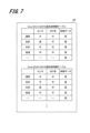
- FIG. 7 is a table configuration diagram of the priority information table 23 in ZoneECU.
- the priority information table 23 in the ZoneECU is a table used by the processing program 21 on the side of the integrated ECU to determine the priority of sensors, entertainment systems, and control data based on the vehicle state.
- FIG. 7 shows an example of the priority information table in ZoneECUs 1 and 2. In FIG. Priority information tables in other ZoneECUs 3 and 4 are omitted from the drawing.
- the processing program 21 on the integrated ECU side refers to the priority information table in ZoneECU1 and ZoneECU4, and sets the priority of the sensor and the control data to "high". Thereafter, the processing program 21 on the integrated ECU side outputs priority information in which the priority of the sensor and control data is changed to "high" to ZoneECUs 1-4.
- FIG. 8 is a flowchart showing an example of processing on the ZoneECU side.
- the priority setting unit 15A (15B, 15C, 15D) mainly shown in FIG. 1 will be described.
- the processing on the ZoneECU side is executed, for example, when various data are received from the integrated ECU side, sensors, entertainment systems, or actuators.
- the priority setting unit 15A (15B, 15C, 15D) receives various data from the integrated ECU 20 (S1), it analyzes the received data.
- the priority setting unit 15A (15B, 15C, 15D) determines whether or not the received data is priority setting information as a result of the analysis (S2).
- the priority setting unit 15A (15B, 15C, 15D) sets the priority information table 12A based on the priority setting information acquired from the integrated ECU 20.
- the priority of (12B, 12C, 12D) is changed, and this processing ends.
- the priority setting unit 15A (15B, 15C, 15D) transmits the received data (control command value) to the actuator 17A (17B, 17C, 17D) (S4), and ends this process.
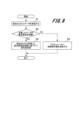
- FIG. 9 is a flowchart showing an example of processing on the integrated ECU side according to the first embodiment.
- an example of processing of the vehicle state determination unit 71 (see FIG. 1) will be mainly described.
- the vehicle state determination unit 71 confirms the vehicle state based on the data received from each ZoneECU (S11). Then, the vehicle state determination unit 71 determines whether or not the vehicle state has changed based on the received data (S12).
- the vehicle state determination unit 71 determines the driving pattern from the confirmed vehicle state. Then, the vehicle state determination unit 71 refers to the priority information table 22 in the driving pattern (S13), and confirms the priority of each ZoneECU in the driving pattern.
- the vehicle state determination unit 71 determines whether or not the priority of each ZoneECU will be changed in accordance with the change in the vehicle state, based on each ZoneECU in the driving pattern (S14).
- the vehicle state determination unit 71 displays the priority information table of the ZoneECU whose priority is to be changed (denoted as "target ZoneECU" in the figure). 23 (S15) to acquire the priority setting information in this ZoneECU. Then, the vehicle state determination unit 71 transmits the priority setting information to the ZoneECU whose priority is to be changed (S16), and ends this process.
- the integrated ECU 20 has the ZoneECU priority setting information, and the running pattern of the vehicle 600 that can be recognized based on changes in the vehicle state or the state outside the vehicle. Accordingly, the priority setting information of the ZoneECU having the higher priority is dynamically changed.
- the ZoneECU transfers data to the integrated ECU 20 according to statically defined priorities in normal times. In this way, the integrated ECU 20 changes the priority of the sensors in the priority information table 12A (12B, 12C, 12D) of the ZoneECU with the higher priority according to the vehicle state or the state outside the vehicle. High sensor information can be acquired early.
- the integrated ECU 20 needs to check whether there is a person or an obstacle on the left side of the vehicle 600. Therefore, sensor information that can be obtained from the sensors 2 and 3 arranged on the left side of the vehicle 600 is can be obtained earlier than other sensor information and used to control the vehicle 600 .
- the integrated ECU 20 can distribute resources required for processing to ZoneECUs with high priority.
- FIG. 10 is a block diagram showing an overall configuration example of a vehicle control system 1000B according to the second embodiment.
- the memory 60 of the integrated ECU 20 stores an ECU priority information table 24 in a sensor failure state
- a sensor state determination program 25 is stored.
- the control unit (CPU 70) has a sensor state determination unit (sensor state determination unit) that determines the state of the sensors (sensors 1 to 5) for recognizing external conditions connected to each of the plurality of area electronic devices (ZoneECUs 1 to 4). 72). Therefore, the CPU 70 of the integrated ECU 20 executes the sensor state determination program 25 read out from the memory 60 to realize the function of the sensor state determination section 72 .
- the sensor state determination unit 72 can determine the state of the sensors 1-5 (whether there is a failure or the like) as the sensor state based on various data acquired from the ZoneECUs 1-4.
- FIG. 11 is a diagram showing the recognition ranges of sensors 1 to 3 mounted on vehicle 600.
- FIG. Here, examples of recognition ranges of sensors 1 to 3 among sensors 1 to 5 mounted on a vehicle 600 as shown in FIG. 2 are shown.
- sensor 1 has a recognition range in front of the vehicle 600
- sensor 2 has a recognition range in front left of the vehicle 600
- sensor 3 has a recognition range in the rear left of the vehicle 600 .
- the recognition range of each sensor is represented by a sector centered approximately on each sensor.
- FIG. 11 shows that the recognition range of sensor 2 can be covered by the recognition ranges of sensors 1 and 3 . Therefore, even if the sensor 2 fails, the information obtained from the sensors 1 and 3 is acquired by the integrated ECU 20 via the ZoneECUs 1 and 4, so that the running of the vehicle 600 is not hindered. Therefore, the vehicle state determination unit (vehicle state determination unit 71) selects another sensor (sensor 2) that can cover the recognition range of the sensor (sensor 2) determined to be broken by the sensor state determination unit (sensor state determination unit 72). 1, 3) are connected to increase the priority of the area electronic devices (ZoneECUs 1 to 4). The failure of the sensor 2 in this way is merely an example, and in the vehicle 600, sensors are redundantly configured such that the recognition ranges of a plurality of sensors overlap at various locations.
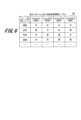
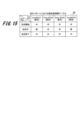
- FIG. 12 is a table configuration diagram of the ECU priority information table 24 in a sensor failure state according to the second embodiment.
- the horizontal axis indicates the failed sensor
- the vertical axis indicates the driving pattern as the vehicle state.
- the sensor state determination unit 72 determines that the sensor has failed, it refers to the ECU priority information table 24 to determine the priority of which ZoneECU based on the current vehicle state. Decide whether to raise
- the integrated ECU 20 raises the priority of the ZoneECU 1 connected to the sensor 1 and the ZoneECU 4 connected to the sensor 3 . Therefore, the integrated ECU 20 can obtain sensor information covering the recognition range of the failed sensor 2 with the recognition ranges of the sensors 1 and 3 that are not in failure. Therefore, even if any one of sensors 1, 3, 4 and 5 other than sensor 2 fails, the priority of the ZoneECU connected to the sensor that can cover the recognition range of the failed sensor is raised.
- FIG. 13 is a functional configuration diagram of a vehicle control system 1000B according to the second embodiment.
- FIG. 13 shows a configuration example of each function of the vehicle control system 1000B in the form of a data flow diagram.
- FIG. 13 briefly shows the flow of information in each part and program of the vehicle control system 1000B.
- the processing program 11A (11B, 11C, 11D) on the ZoneECU side shown in the upper part of FIG. 13 is the same as the first embodiment explained in FIG. 4, so detailed explanation is omitted.
- a processing program 21 on the integrated ECU side shown in the lower part of FIG. 13 will be described.
- the processes (11) to (16) are the same as the example of the processing program 21 on the integrated ECU side shown in the lower part of FIG.
- the processing program 21 on the integrated ECU side determines that the vehicle state has not changed based on the information received from the ZoneECUs 1 to 4, the state of the sensor is determined.
- the program 25 determines the sensor states of the sensors 1-5.
- the processing program 21 on the integrated ECU side executes the ECU priority information table 24 in the sensor state. to determine whether there is a change in the priority of ZoneECU. After that, the processing program 21 on the integrated ECU side acquires the information of the ZoneECU whose priority has been changed. Then, the processing program 21 on the integrated ECU side outputs the priority setting information to the ZoneECU whose priority is changed.
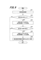
- FIG. 14 is a flowchart showing an example of processing on the integrated ECU side according to the second embodiment.
- the same step numbers are given to the same processes (S11 to S16) as the processes on the integrated ECU side according to the first embodiment shown in FIG. 9, and the description of the processes is omitted. do.
- step S12 when the vehicle state determination unit 71 determines that the vehicle state has not changed (NO in S12), the sensor state determination unit 72 checks the sensor states of the sensors connected to each ZoneECU. (S21). Then, the sensor state determination unit 72 determines whether or not a failure has occurred in the sensor (S22).
- the sensor state determination unit 72 determines that the sensor has failed (YES in S22)
- the sensor state determination unit 72 refers to the ECU priority information table 24 in the sensor failure state (S23), and determines whether the sensor has failed.
- Information of ZoneECUs connected to other sensors capable of covering the sensor recognition range (for example, information of ZoneECUs 1 and 4 when sensor 2 fails) is acquired.
- the vehicle state determination unit 71 determines whether or not there is a change in the priority of the priority information table for each ZoneECU based on the information of the ZoneECU (S14).
- the processing after step S14 is the same as the processing described above.
- step S22 determines in step S22 that no sensor failure has occurred (NO in S22), or if the vehicle state determination unit 71 determines in step S14 that the priority has not been changed. If so (NO in S14), this process ends.
- the sensor state determination unit 72 of the integrated ECU 20 checks the sensor state of the sensors connected to each ZoneECU.
- the sensor state determination unit 72 refers to the ECU priority information table 24 in the sensor failure state, and obtains information about the ZoneECU to which the redundant sensor is connected.
- the vehicle state determination unit 71 increases the priority of the ZoneECU.
- the processing program 21 on the side of the integrated ECU according to the second embodiment switches the priority of the ZoneECU according to the sensor state, thereby appropriately switching the priority information when a sensor failure occurs. It becomes possible.
- the number of sensor failures is not limited to one, and the vehicle control system 1000B according to the second embodiment can handle multiple sensor failures. If the recognition range of the faulty sensor can be covered by the recognition range of the non-faulty sensor, the integrated ECU 20 still changes the priority of the ZoneECU connected to the non-faulty sensor to a higher priority.
- the vehicle state includes left turn, right turn, and the like. However, if the priority is changed according to stages such as the initial stage, the intermediate stage, and the final stage of the left turn, the vehicle 600 can travel more safely and reliably. Therefore, vehicle control systems according to modifications of the first and second embodiments of the present invention will be described with reference to FIGS. 15 and 16.
- FIG. in the vehicle control system according to the modified example the operation of vehicle 600 is divided, and processing for changing the priority of ZoneECU for each divided operation is performed.
- the vehicle state determination unit updates the first priority information table (priority information table 22 in the driving pattern) and the second 2 By referring to the priority information table (priority information table 23 in each ZoneECU), area electronic devices (ZoneECUs 1 to 4 ) to change the priority. Specific examples are described below.
- FIG. 15 is a table configuration diagram showing an example of the priority information table 22 for driving patterns according to the third embodiment.
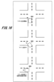
- FIG. 16 is a top view of vehicle 600 turning left at an intersection.
- three types of operation examples of changes over time ie, the start of left turn, the middle of left turn, and the end of left turn, are defined as the running pattern during left turn running (vehicle motion).
- the integrated ECU 20 determines that the vehicle 600 passes through a high-risk location based on past data
- the integrated ECU 20 connects a ZoneECU connected with a sensor capable of acquiring information around the high-risk location when the vehicle 600 passes through.
- the integrated ECU 20 may perform control such that when the vehicle 600 passes through the location, the ZoneECU connected to a sensor capable of acquiring information around the location has a higher priority.
- a plurality of types of operations are defined as the running pattern of the vehicle 600 according to the passage of time.
- the priority of the ZoneECU is defined for each operation. Therefore, the integrated ECU 20 can change the priority of the ZoneECU according to the operation of the vehicle 600 traveling in a certain traveling pattern, and acquire more detailed information.
Landscapes
- Engineering & Computer Science (AREA)
- Automation & Control Theory (AREA)
- Human Computer Interaction (AREA)
- Transportation (AREA)
- Mechanical Engineering (AREA)
- Small-Scale Networks (AREA)
- Traffic Control Systems (AREA)
- Stored Programmes (AREA)
Priority Applications (5)
| Application Number | Priority Date | Filing Date | Title |
|---|---|---|---|
| PCT/JP2021/041130 WO2023084581A1 (ja) | 2021-11-09 | 2021-11-09 | 電子制御装置及び車両制御システム |
| CN202180102369.1A CN117980209A (zh) | 2021-11-09 | 2021-11-09 | 电子控制装置及车辆控制系统 |
| JP2023559217A JP7629539B2 (ja) | 2021-11-09 | 2021-11-09 | 電子制御装置及び車両制御システム |
| DE112021008453.4T DE112021008453T5 (de) | 2021-11-09 | 2021-11-09 | Elektronische steuervorrichtung und fahrzeugsteuersystem |
| US18/698,503 US20240416936A1 (en) | 2021-11-09 | 2021-11-09 | Electronic control device and vehicle control system |
Applications Claiming Priority (1)
| Application Number | Priority Date | Filing Date | Title |
|---|---|---|---|
| PCT/JP2021/041130 WO2023084581A1 (ja) | 2021-11-09 | 2021-11-09 | 電子制御装置及び車両制御システム |
Publications (1)
| Publication Number | Publication Date |
|---|---|
| WO2023084581A1 true WO2023084581A1 (ja) | 2023-05-19 |
Family
ID=86335304
Family Applications (1)
| Application Number | Title | Priority Date | Filing Date |
|---|---|---|---|
| PCT/JP2021/041130 Ceased WO2023084581A1 (ja) | 2021-11-09 | 2021-11-09 | 電子制御装置及び車両制御システム |
Country Status (5)
| Country | Link |
|---|---|
| US (1) | US20240416936A1 (https=) |
| JP (1) | JP7629539B2 (https=) |
| CN (1) | CN117980209A (https=) |
| DE (1) | DE112021008453T5 (https=) |
| WO (1) | WO2023084581A1 (https=) |
Citations (3)
| Publication number | Priority date | Publication date | Assignee | Title |
|---|---|---|---|---|
| JP2021011231A (ja) * | 2019-07-09 | 2021-02-04 | マツダ株式会社 | 車載ネットワークシステム |
| JP2021129278A (ja) * | 2020-02-17 | 2021-09-02 | 矢崎総業株式会社 | 通信システム |
| JP2021135809A (ja) * | 2020-02-27 | 2021-09-13 | マツダ株式会社 | 車載機器制御装置 |
Family Cites Families (8)
| Publication number | Priority date | Publication date | Assignee | Title |
|---|---|---|---|---|
| US8229618B2 (en) * | 2008-09-11 | 2012-07-24 | Deere & Company | Leader-follower fully autonomous vehicle with operator on side |
| JP2017147598A (ja) * | 2016-02-17 | 2017-08-24 | トヨタ自動車株式会社 | ネットワークシステム |
| JP6782188B2 (ja) * | 2016-05-27 | 2020-11-11 | パナソニック インテレクチュアル プロパティ コーポレーション オブ アメリカPanasonic Intellectual Property Corporation of America | 電子制御ユニット、通信方法及び車載ネットワークシステム |
| US20230102518A1 (en) * | 2021-09-30 | 2023-03-30 | Transportation Ip Holdings, Llc | Vehicle prioritization system and method |
| JP7192501B2 (ja) * | 2017-02-16 | 2022-12-20 | 住友電気工業株式会社 | 車外通信装置、車載装置、車載通信システム、通信制御方法および通信制御プログラム |
| KR102163895B1 (ko) * | 2018-07-16 | 2020-10-12 | 엘지전자 주식회사 | 차량 제어 장치 및 그것을 포함하는 차량 |
| JP2021081886A (ja) * | 2019-11-18 | 2021-05-27 | 株式会社デンソー | 車載用の計測装置ユニットおよび車載用の計測装置ユニットにおける統合データ生成方法 |
| CN111366192B (zh) * | 2020-03-16 | 2022-05-13 | 华为技术有限公司 | 信息获取方法及装置 |
-
2021
- 2021-11-09 CN CN202180102369.1A patent/CN117980209A/zh active Pending
- 2021-11-09 US US18/698,503 patent/US20240416936A1/en active Pending
- 2021-11-09 DE DE112021008453.4T patent/DE112021008453T5/de active Pending
- 2021-11-09 JP JP2023559217A patent/JP7629539B2/ja active Active
- 2021-11-09 WO PCT/JP2021/041130 patent/WO2023084581A1/ja not_active Ceased
Patent Citations (3)
| Publication number | Priority date | Publication date | Assignee | Title |
|---|---|---|---|---|
| JP2021011231A (ja) * | 2019-07-09 | 2021-02-04 | マツダ株式会社 | 車載ネットワークシステム |
| JP2021129278A (ja) * | 2020-02-17 | 2021-09-02 | 矢崎総業株式会社 | 通信システム |
| JP2021135809A (ja) * | 2020-02-27 | 2021-09-13 | マツダ株式会社 | 車載機器制御装置 |
Also Published As
| Publication number | Publication date |
|---|---|
| US20240416936A1 (en) | 2024-12-19 |
| JP7629539B2 (ja) | 2025-02-13 |
| JPWO2023084581A1 (https=) | 2023-05-19 |
| DE112021008453T5 (de) | 2024-09-05 |
| CN117980209A (zh) | 2024-05-03 |
Similar Documents
| Publication | Publication Date | Title |
|---|---|---|
| JP6611664B2 (ja) | 自動運転制御装置および自動運転制御方法 | |
| JP7193289B2 (ja) | 車載電子制御システム | |
| JP7430734B2 (ja) | 車両内通信システム、車両内通信方法、およびデバイス | |
| CN113195330B (zh) | 电子控制装置以及车载系统 | |
| JP6388871B2 (ja) | ドライバー・アシスタント・アプリケーション用の方法 | |
| JP7198056B2 (ja) | 車両制御装置及び車両制御方法 | |
| JP7211487B2 (ja) | 車両制御システム、車両の制御方法及び車両の制御プログラム | |
| JP2005521182A (ja) | 制御装置の冗長アレイ | |
| JP2019185246A (ja) | 自動運転制御システム | |
| WO2021250936A1 (ja) | 走行制御装置及び走行制御方法 | |
| WO2020059350A1 (ja) | 電子制御装置 | |
| JP3866536B2 (ja) | 車両の自動運転システム | |
| US12304509B2 (en) | Method for controlling a vehicle | |
| KR20180082886A (ko) | 자율주행시스템의 사고 예방을 위한 프로세서 및 동작 방법 | |
| CN115179943A (zh) | 机动车的自动引导 | |
| US11318929B2 (en) | Electronic control apparatus, electronic control system, and electronic control method | |
| JP7221070B2 (ja) | 電子制御装置、制御方法 | |
| CN115525012B (zh) | 车辆控制方法、装置、车辆及存储介质 | |
| CN113710558B (zh) | 车辆控制装置以及计算机程序 | |
| JP3851522B2 (ja) | 車両の自動運転システム | |
| JP7629539B2 (ja) | 電子制御装置及び車両制御システム | |
| JP7521639B2 (ja) | 運転制御システム | |
| JP7702037B2 (ja) | 演算処理装置、演算処理方法 | |
| JP6987201B1 (ja) | 車両制御装置及び車両制御方法 | |
| KR102405002B1 (ko) | Mrm 지원을 위한 자율 주행 시스템 |
Legal Events
| Date | Code | Title | Description |
|---|---|---|---|
| 121 | Ep: the epo has been informed by wipo that ep was designated in this application |
Ref document number: 21963947 Country of ref document: EP Kind code of ref document: A1 |
|
| WWE | Wipo information: entry into national phase |
Ref document number: 2023559217 Country of ref document: JP |
|
| WWE | Wipo information: entry into national phase |
Ref document number: 202180102369.1 Country of ref document: CN |
|
| WWE | Wipo information: entry into national phase |
Ref document number: 18698503 Country of ref document: US |
|
| WWE | Wipo information: entry into national phase |
Ref document number: 112021008453 Country of ref document: DE |
|
| 122 | Ep: pct application non-entry in european phase |
Ref document number: 21963947 Country of ref document: EP Kind code of ref document: A1 |