WO2023084581A1 - 電子制御装置及び車両制御システム - Google Patents
電子制御装置及び車両制御システム Download PDFInfo
- Publication number
- WO2023084581A1 WO2023084581A1 PCT/JP2021/041130 JP2021041130W WO2023084581A1 WO 2023084581 A1 WO2023084581 A1 WO 2023084581A1 JP 2021041130 W JP2021041130 W JP 2021041130W WO 2023084581 A1 WO2023084581 A1 WO 2023084581A1
- Authority
- WO
- WIPO (PCT)
- Prior art keywords
- vehicle
- priority
- state
- information
- sensor
- Prior art date
Links
- 230000008859 change Effects 0.000 claims abstract description 32
- 230000007704 transition Effects 0.000 claims description 3
- 238000012545 processing Methods 0.000 description 33
- 238000010586 diagram Methods 0.000 description 26
- 238000000034 method Methods 0.000 description 21
- 230000008569 process Effects 0.000 description 10
- 230000006870 function Effects 0.000 description 6
- 230000004048 modification Effects 0.000 description 4
- 238000012986 modification Methods 0.000 description 4
- 238000004891 communication Methods 0.000 description 3
- 238000001514 detection method Methods 0.000 description 2
- 239000004065 semiconductor Substances 0.000 description 2
- 238000012546 transfer Methods 0.000 description 2
- 230000001133 acceleration Effects 0.000 description 1
- 230000009471 action Effects 0.000 description 1
- 238000004590 computer program Methods 0.000 description 1
- 239000000470 constituent Substances 0.000 description 1
- 230000007613 environmental effect Effects 0.000 description 1
- 238000003384 imaging method Methods 0.000 description 1
- 230000010365 information processing Effects 0.000 description 1
- 230000002093 peripheral effect Effects 0.000 description 1
- 230000002250 progressing effect Effects 0.000 description 1
- 230000004044 response Effects 0.000 description 1
- 239000007787 solid Substances 0.000 description 1
Images


Classifications
-
- B—PERFORMING OPERATIONS; TRANSPORTING
- B60—VEHICLES IN GENERAL
- B60W—CONJOINT CONTROL OF VEHICLE SUB-UNITS OF DIFFERENT TYPE OR DIFFERENT FUNCTION; CONTROL SYSTEMS SPECIALLY ADAPTED FOR HYBRID VEHICLES; ROAD VEHICLE DRIVE CONTROL SYSTEMS FOR PURPOSES NOT RELATED TO THE CONTROL OF A PARTICULAR SUB-UNIT
- B60W50/00—Details of control systems for road vehicle drive control not related to the control of a particular sub-unit, e.g. process diagnostic or vehicle driver interfaces
- B60W50/06—Improving the dynamic response of the control system, e.g. improving the speed of regulation or avoiding hunting or overshoot
Definitions
- the present invention relates to electronic control units and vehicle control systems.
- Zone Architecture In recent years, in order to reduce costs, a method called Zone Architecture has been developed, in which a ZoneECU (Electronic Control Unit), which is an example of an area electronic device, is placed in each area of the vehicle, and information from the ZoneECU is aggregated into an integrated ECU. progressing. As the level of the automated driving system improves, the number of sensors connected to ZoneECU increases. Various types of information are transmitted from the ZoneECU to the integrated ECU according to priority. For example, the control information is set to "high" in priority and transmitted with the highest priority. On the other hand, the sensor information has a priority of "middle", and the entertainment information has a priority of "low”. That is, the ZoneECU sends the control information, the sensor information, and the entertainment information in this order to the integrated ECU. By the way, it was necessary to change the priority of data transfer depending on the state of the vehicle.
- a ZoneECU Electronic Control Unit
- Patent Document 1 has been known as a method for setting the priority of various types of information.
- this patent document 1 "When performing automatic driving control, it is possible to set a high priority to data from an external device located in an important peripheral area where it is necessary to confirm whether or not an object exists. You can.”
- Patent Document 1 sets the priority of data obtained from an external communication device. With this method, it was not possible to set the priority of the sensor to be acquired depending on the state of the vehicle (for example, turning left).
- the present invention has been made in view of such circumstances, and an object of the present invention is to change the priority of area electronic devices according to changes in vehicle conditions.
- the electronic control device controls the vehicle based on one or more pieces of information obtained from a plurality of area electronic devices provided for each area of the vehicle.
- This electronic control unit is provided for each of a plurality of area electronic devices, and includes a first priority information table in which the priority of the area electronic device that acquires information is set, and a table that changes the state of the vehicle according to the external conditions of the vehicle. If so, the first priority information table is referred to determine the area electronic device whose priority is to be changed according to the changing vehicle state, and the determined area electronic device is instructed to change the priority. and a control unit for obtaining changed information with a higher priority from the area electronic device that instructed to change the priority.
- the priorities of the area electronic devices are changed according to changes in the state of the vehicle, it is possible to preferentially obtain information from the area electronic devices with higher priority.
- FIG. 1 is a block diagram showing an example of the overall configuration of a vehicle control system according to a first embodiment of the invention
- FIG. 1 is a schematic diagram showing an arrangement example of a sensor, a ZoneECU, and an integrated ECU in a vehicle according to a first embodiment of the present invention
- FIG. It is a figure which shows the example which looked at the situation which the vehicle which concerns on the 1st Embodiment of this invention is turning left from the top.
- 1 is a functional configuration diagram of a vehicle control system according to a first embodiment of the invention
- FIG. FIG. 4 is a table configuration diagram of a current priority information table provided for each ZoneECU according to the first embodiment of the present invention
- FIG. 4 is a table configuration diagram of a priority information table in a driving pattern according to the first embodiment of the present invention
- FIG. 4 is a table configuration diagram of a priority information table in ZoneECU according to the first embodiment of the present invention
- FIG. 4 is a flowchart showing an example of processing on the ZoneECU side according to the first embodiment of the present invention
- 4 is a flowchart showing an example of processing on the integrated ECU side according to the first embodiment of the present invention
- FIG. 2 is a block diagram showing an example of the overall configuration of a vehicle control system according to a second embodiment of the invention
- FIG. FIG. 7 is a diagram showing recognition ranges of sensors mounted on a vehicle according to a second embodiment of the present invention
- FIG. 9 is a table configuration diagram of an ECU priority information table in a sensor failure state according to the second embodiment of the present invention
- FIG. 2 is a functional configuration diagram of a vehicle control system according to a second embodiment of the invention
- FIG. FIG. 9 is a flowchart showing an example of processing on the side of an integrated ECU according to the second embodiment of the present invention
- FIG. 11 is a table configuration diagram of a priority information table in a driving pattern according to a modification of the first and second embodiments of the present invention
- FIG. FIG. 10 is a top view of a vehicle according to a modification of the first and second embodiments of the present invention, which makes a left turn at an intersection;
- the processor may perform the entire processing described below.
- the processing described with the program as the subject of operation may be processing performed by a device including a processor. It may also include a dedicated hardware circuit that performs part or all of the processing performed by the processor.
- a computer program may be installed on the device from a program source.
- the program source may be, for example, a program distribution server or a computer-readable non-transitory recording medium.
- FIG. 1 is a block diagram showing an example of the overall configuration of a vehicle control system according to the first embodiment.
- the vehicle control system 1000A is an example of a control system that is installed in a vehicle 600 (see FIG. 2 described later) such as an automobile and that controls the operation of the vehicle 600 .
- the vehicle control system 1000A includes various sensors 13A (13B, 13C, 13D, 14A), entertainment information devices 16A (16B, 16C, 16D), various actuators 17A (17B, 17C, 17D), and a vehicle 600. and a ZoneECU 10A (10B, 10C, 10D) that controls each area such as the direction (for example, left front, left rear, right front, right rear).
- the vehicle control system 1000A also includes an integrated ECU 20 that collects data from the ZoneECUs 10A (10B, 10C, and 10D), recognizes an object outside the vehicle, recognizes the object, determines the operation of the vehicle, and controls the running of the vehicle. .
- This electronic control unit integrated ECU 20 controls the vehicle (vehicle 600) based on one or more pieces of information acquired from a plurality of area electronic devices (ZoneECUs 1 to 4) provided for each area of the vehicle (vehicle 600). can be controlled.
- the entertainment information equipment 16A (16B, 16C, 16D) is abbreviated as "ENT system”.
- ENT system As entertainment information transmitted from the entertainment information device 16A (16B, 16C, 16D) to the ZoneECU 10A (10B, 10C, 10D), for example, the current position of the vehicle 600 obtained from a car navigation system (not shown) installed in the vehicle 600. There is information indicating
- sensors 13A, 14A, 13B, 13C, and 13D are called sensors 1, 2, 3, 4, and 5 or sensors 1-5, respectively.
- Sensors 1 to 5 are used to acquire information of the surrounding environment of vehicle 600 such as Radar (Radio Detection and Ranging), LiDAR (Light/Laser Imaging Detection and Ranging), and cameras.
- Sensors 1-5 output information that each sensor can acquire to one of ZoneECUs 1-4 to which the sensors are connected.
- ZoneECUs 10A (10B, 10C, 10D) are referred to as ZoneECUs 1, 2, 3, 4 or ZoneECUs 1 to 4, respectively.
- ZoneECUs 1 to 4 when the ZoneECUs 1 to 4 are not distinguished, they may be called only by "ZoneECU".
- a ZoneECU is used as an example of an area electronic device. ZoneECUs 1 to 4 are arranged in areas (directions) within the vehicle. The sensors placed in the ZoneECUs 1 to 4 are placed in optimal locations so that they can recognize their respective areas (directions).
- Sensors 1 to 5 entertainment information equipment 16A (16B, 16C, 16D), various actuators 17A (17B, 17C, 17D), ZoneECUs 1 to 4, and integrated ECU 20 are connected to an in-vehicle network 30A (30B, 30C, 30D) and an in-vehicle network 40A (40B, 40C, 40D).
- the in-vehicle network 30A (30B, 30C, 30D) and the in-vehicle network 40A (40B, 40C, 40D) are composed of arbitrary communication networks such as Ethernet (registered trademark) and CAN-FD (CAN with Flexible Data-Rate). be done.
- Ethernet registered trademark
- CAN-FD CAN with Flexible Data-Rate
- ZoneECUs 1-4 each include a CPU 55A (55B, 55C, 55D) and a memory 50A (50B, 50C, 50D).
- the CPU 55A (55B, 55C, 55D) reads a program stored in the memory 50A (50B, 50C, 50D) and executes each process according to this program.
- the memory 50A (50B, 50C, 50D) is composed of, for example, RAM (Random Access Memory) and ROM (Read Only Memory).
- the memory 50A (50B, 50C, 50D) stores a ZoneECU-side processing program 11A (11B, 11C, 11D) executed by the CPU 55A (55B, 55C, 55D) and information necessary for ZoneECU processing.
- the information necessary for ZoneECU processing is, for example, a priority information table 12A (12B, 12C, 12D) that the ZoneECUs 1 to 4 refer to when transmitting data to the integrated ECU 20, and the like.
- a detailed configuration example of the priority information table 12A (12B, 12C, 12D) will be described later with reference to FIG.
- the CPU 55A (55B, 55C, 55D) of the ZoneECU executes the ZoneECU-side processing program 11A (11B, 11C, 11D) read out from the memory 50A (50B, 50C, 50D), thereby executing the priority setting unit 15A (15B). , 15C, 15D).
- the priority setting unit 15A (15B, 15C, 15D) changes the priority of the priority information table 12A (12B, 12C, 12D) based on the priority setting information input from the integrated ECU 20.
- the integrated ECU 20 includes a CPU 70 and a memory 60.
- CPU 70 executes each process according to a program stored in memory 60 .
- the CPU 70 is used as an example of a control section according to the present embodiment.
- the control unit determines that the state of the vehicle (vehicle 600) changes from the external conditions of the vehicle (vehicle 600)
- the control unit refers to the first priority information table (priority information table 22 in driving pattern), determining the area electronic devices (ZoneECUs 1 to 4) whose priorities are to be changed according to the changing state of the vehicle (vehicle 600), instructing the determined area electronic devices (ZoneECUs 1 to 4) to change the priority;
- the changed information with higher priority is obtained from the area electronic devices (ZoneECUs 1 to 4) that instructed to change the priority.
- the memory 60 is composed of, for example, a RAM and a ROM, and stores the processing program 21 on the integrated ECU side executed by the CPU 70 and information necessary for the processing of the integrated ECU 20 .
- the necessary information of the integrated ECU 20 is, for example, information stored in the priority information table 22 of ZoneECUs 1-4 in the running pattern of the vehicle 600 and the priority information table 23 of each ZoneECU 1-4.
- the first priority information table (priority information table 22 in driving pattern) is provided for each of a plurality of area electronic devices (ZoneECUs 1 to 4). degree is set.
- the second priority information table (priority information table 23 in each ZoneECU) stores the state of the vehicle (vehicle 600) and the area electronic device ( Defines the relationship with the priority of information transmitted by ZoneECUs 1 to 4).
- a vehicle state determination unit (vehicle state determination unit 71) of the control unit (CPU 70) determines a change in the state of the vehicle (vehicle 600) based on the external situation, and determines whether the state of the vehicle (vehicle 600) changes.
- the priority defined in the second priority information table (priority information table 23 in each ZoneECU) is the second priority information table (priority information in each ZoneECU) after the state of the vehicle (vehicle 600) changes.
- the vehicle state determination unit 71 can determine the state of the vehicle 600 as the vehicle state based on various data acquired from the ZoneECUs 1 to 4, and can recognize the running pattern of the vehicle 600.
- Various entertainment-related information devices 16A (16B, 16C, 16D) are information devices that are not necessary for running control of the vehicle 600, such as navigation information and music information.
- the various actuators 17A (17B, 17C, 17D) include one or more actuators that control the operation of corresponding devices in response to accelerator, brake, steering, etc. (not shown) operated by the driver of the vehicle 600.
- Various actuators 17 ⁇ /b>A 17 ⁇ /b>B, 17 ⁇ /b>C, 17 ⁇ /b>D
- control the operation of equipment related to running mounted on vehicle 600 based on control information input from integrated ECU 20 .
- the various actuators 17A (17B, 17C, 17D) notify the integrated ECU 20 of vehicle control information indicating the current control state of the vehicle 600.
- the integrated ECU 20 Based on the vehicle control information notified from the actuators 17A (17B, 17C, 17D), the integrated ECU 20 instructs the various actuators 17A (17B, 17C, 17D) with control information such as acceleration/deceleration and steering fine adjustment. Is possible.
- the program may be described as an operating subject for convenience, but the actual executing subject is the CPU 55A (55B, 55C, 55D, 70) that executes the program.
- the integrated ECU 20 can also have an arithmetic element capable of various types of information processing, such as an FPGA (Field-Programmable Gate Array).
- the integrated ECU 20 can also have a magnetic storage medium such as a HDD (Hard Disk Drive) or a semiconductor storage medium such as an SSD (Solid State Drive) other than the RAM and ROM as the memory 60 .
- Various programs, parameters, etc. may be stored in these magnetic storage media and semiconductor storage media.
- FIG. 2 is a schematic diagram showing an arrangement example of sensors 1 to 5, ZoneECUs 1 to 4, and integrated ECU 20 in vehicle 600 according to the first embodiment.
- the placement positions of the sensors include any one of the front right, front left, rear right, and rear left of the vehicle (vehicle 600).
- a sensor 1 is installed in the front center of the vehicle 600
- a sensor 2 is installed in the front left
- a sensor 3 is installed in the rear left
- a sensor 4 is installed in the front right
- a sensor 4 is installed in the rear right. 5 is installed.
- Vehicle 600 is divided into at least four areas. For example, the front left, rear left, front right, and rear right of the vehicle 600 are divided as areas. ZoneECUs 1 to 4 are provided for each area.
- a plurality of area electronic devices are arranged in the vicinity of the arrangement positions of the sensors (sensors 1 to 5) arranged on the vehicle (vehicle 600).
- sensors 1 and 2 are connected to ZoneECU 1 provided on the front left of vehicle 600 .
- Sensor 3 is connected to ZoneECU 4 provided on the rear left of vehicle 600 .
- Sensor 4 is connected to ZoneECU 2 provided on the front right of vehicle 600 .
- Sensor 5 is connected to ZoneECU 3 provided on the rear right of vehicle 600 .
- ZoneECUs 1 to 4 are connected to an integrated ECU 20 arranged near the center of vehicle 600 .
- FIG. 3 is a top view showing an example of a situation in which vehicle 600 is turning left. Here, an example of a travel pattern when vehicle 600 makes a left turn at intersection 700 is shown.
- the running pattern of vehicle 600 is defined in advance. Then, the priority of the ZoneECU changes according to the driving pattern. For example, in a driving pattern in which vehicle 600 makes a left turn, ZoneECUs 1 and 4 (see FIG. 2) arranged in the area on the left side of vehicle 600 have a higher priority than other ZoneECUs 2 and 3 . Therefore, the integrated ECU 20 preferentially acquires information from the ZoneECUs 1 and 4 and executes processing based on this information.
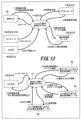
- FIG. 4 is a functional configuration diagram of the vehicle control system 1000A according to the first embodiment.
- FIG. 4 shows a configuration example of each function of the vehicle control system 1000A in the form of a data flow diagram. This FIG. 4 is described in a form called a state transition diagram or a state machine diagram, and briefly shows the flow of information in each part and program of the vehicle control system 1000A.
- the vehicle state determination unit (vehicle state determination unit 71) determines the state of the vehicle (vehicle 600) and the state transition of the vehicle (vehicle 600) based on a state machine that determines the state of the vehicle (vehicle 600) from the external situation. determine the state of
- the vehicle control system 1000A includes a priority information table 12A (12B, 12C, 12D) on the ZoneECU side and priority information tables 22 and 23 on the integrated ECU side.
- the respective processing programs executed by the ZoneECUs 1 to 4 and the integrated ECU 20 are executed by the CPU 55A (55B, 55C, 55D, 70) to perform the respective functions according to the present embodiment. is realized. First, an example of processing of ZoneECUs 1 to 4 shown on the upper side of FIG. 4 will be described.
- the processing program 11A (11B, 11C, 11D) on the ZoneECU side is executed by the CPU 55A (55B, 55C, 55D) on the ZoneECU side in the following procedures (1) to (8).
- procedures (1) to (8) do not necessarily have to be executed in order, and any one of the procedures may be executed in parallel or in reverse order.
- the processing program 11A (11B, 11C, 11D) on the ZoneECU side receives a control command value or priority setting information from the integrated ECU 20, it controls each section.
- the information received from the integrated ECU 20 may be at least one of the control command value of the vehicle 600 and the priority setting information.
- the processing program 11A (11B, 11C, 11D) on the ZoneECU side returns data corresponding to the information received from the integrated ECU 20 to the integrated ECU 20.
- This data includes vehicle control information received by the processing program 11A (11B, 11C, 11D) on the ZoneECU side from the actuator 17A (17B, 17C, 17D), priority information table 12A (12B, 12C) shown in FIG. , 12D), information detected by sensors 1 to 5 (described as "sensor input” in the figure), entertainment information received from entertainment information equipment 16A (16B, 16C, 16D) includes any of
- the processing program 11A (11B, 11C, 11D) on the ZoneECU side outputs the control command value input from the integrated ECU 20 to the actuator 17A (17B, 17C, 17D).
- the actuator 17A (17B, 17C, 17D) outputs the vehicle control information to the processing program 11A (11B, 11C, 11D) on the ZoneECU side.
- the processing program 11A (11B, 11C, 11D) on the ZoneECU side refers to the priority information table 12A (12B, 12C, 12D) to determine the priority.
- the priority of changing the information table 12A (12B, 12C, 12D) is determined.
- the processing program 11A (11B, 11C, 11D) on the ZoneECU side acquires the determined priority information.
- Information detected by the sensors 1 to 5 is input to the processing program 11A (11B, 11C, 11D) on the ZoneECU side.
- Entertainment information is input to the processing program 11A (11B, 11C, 11D) on the ZoneECU side from the entertainment information devices 16A (16B, 16C, 16D).
- the types of data that the processing program 11A (11B, 11C, 11D) on the ZoneECU side outputs to the integrated ECU 20 are determined by the priority information stored in the priority information table 12A (12B, 12C, 12D). Therefore, when the ZoneECU-side processing program 11A (11B, 11C, 11D) rewrites the priority information in the priority information table 12A (12B, 12C, 12D) and determines the priority information, the ZoneECU-side processing program 11A ( 11B, 11C, 11D) outputs sensor information and control information to the integrated ECU 20 according to the determined priority information.
- FIG. 5 is a table configuration diagram of the current priority information table 12A (12B, 12C, 12D) provided for each of ZoneECUs 1-4.
- the priority information table 12A (12B, 12C, 12D) is a table in which the priority of information output by the target ZoneECU is set. As shown in FIGS. 1 and 5, a priority information table 12A (12B, 12C, 12D) is prepared for each ZoneECU. Each ZoneECU, upon receiving the priority change information from the integrated ECU 20, updates the information in the priority information table 12A (12B, 12C, 12D). For example, when the ZoneECU 1 receives priority change information for setting the sensor to "high" from the integrated ECU 20, the processing program 11A on the ZoneECU side shown in FIG. 4 changes the sensor in the priority information table 12A to "high".
- the processing of the processing program 21 on the integrated ECU side shown in the lower part of FIG. 4 is performed in the following procedures (11) to (16).
- procedures (11) to (16) do not necessarily have to be executed in order, and any one of the procedures may be executed in parallel or in reverse order.
- the processing program 21 on the side of the integrated ECU receives information from ZoneECUs 1-4. In the drawing, receiving information from ZoneECUs 1-4 is described as "data input”. Then, the processing program 21 on the side of the integrated ECU judges the vehicle state based on the received information.
- the processing program 21 on the side of the integrated ECU refers to the priority information table 22 for driving patterns based on the state determination result (for example, the driving pattern of the vehicle 600). (13) Then, the processing program 21 on the integrated ECU side determines a ZoneECU from which information is preferentially acquired.
- the processing program 21 on the integrated ECU side refers to the priority information table 23 in this ZoneECU based on the priority ZoneECU determined from the ZoneECUs 1-4. (15) Then, the processing program 21 on the integrated ECU side determines priority setting information for each ZoneECU according to the driving pattern of the vehicle 600 determined based on the priority information table 23 for the ZoneECU. (16) Then, the processing program 21 on the side of the integrated ECU outputs the control command value or priority setting information of the vehicle 600 to the ZoneECUs 1-4.
- the information that the processing program 21 on the integrated ECU side outputs to the ZoneECUs 1 to 4 may be at least one of the control command value and the priority setting information of the vehicle 600 .
- priority information tables on the integrated ECU side two types will be explained. As shown in FIGS. 1 and 4, two types of tables, a priority information table 22 for driving patterns and a priority information table 23 for each ZoneECU, are provided as priority information tables on the integrated ECU side.
- FIG. 6 is a table configuration diagram of the priority information table 22 in driving patterns.
- the integrated ECU 20 can refer to the priority information table 22 in the driving pattern and determine the priority of each ZoneECU based on the vehicle state. For example, if the vehicle state is normal (for example, driving straight ahead), the driving pattern of the priority information table 22 in the driving pattern uses the priority information for the "normal" driving pattern. That is, the priority of ZoneECUs 1 to 4 is all "medium".
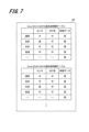
- FIG. 7 is a table configuration diagram of the priority information table 23 in ZoneECU.
- the priority information table 23 in the ZoneECU is a table used by the processing program 21 on the side of the integrated ECU to determine the priority of sensors, entertainment systems, and control data based on the vehicle state.
- FIG. 7 shows an example of the priority information table in ZoneECUs 1 and 2. In FIG. Priority information tables in other ZoneECUs 3 and 4 are omitted from the drawing.
- the processing program 21 on the integrated ECU side refers to the priority information table in ZoneECU1 and ZoneECU4, and sets the priority of the sensor and the control data to "high". Thereafter, the processing program 21 on the integrated ECU side outputs priority information in which the priority of the sensor and control data is changed to "high" to ZoneECUs 1-4.
- FIG. 8 is a flowchart showing an example of processing on the ZoneECU side.
- the priority setting unit 15A (15B, 15C, 15D) mainly shown in FIG. 1 will be described.
- the processing on the ZoneECU side is executed, for example, when various data are received from the integrated ECU side, sensors, entertainment systems, or actuators.
- the priority setting unit 15A (15B, 15C, 15D) receives various data from the integrated ECU 20 (S1), it analyzes the received data.
- the priority setting unit 15A (15B, 15C, 15D) determines whether or not the received data is priority setting information as a result of the analysis (S2).
- the priority setting unit 15A (15B, 15C, 15D) sets the priority information table 12A based on the priority setting information acquired from the integrated ECU 20.
- the priority of (12B, 12C, 12D) is changed, and this processing ends.
- the priority setting unit 15A (15B, 15C, 15D) transmits the received data (control command value) to the actuator 17A (17B, 17C, 17D) (S4), and ends this process.
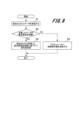
- FIG. 9 is a flowchart showing an example of processing on the integrated ECU side according to the first embodiment.
- an example of processing of the vehicle state determination unit 71 (see FIG. 1) will be mainly described.
- the vehicle state determination unit 71 confirms the vehicle state based on the data received from each ZoneECU (S11). Then, the vehicle state determination unit 71 determines whether or not the vehicle state has changed based on the received data (S12).
- the vehicle state determination unit 71 determines the driving pattern from the confirmed vehicle state. Then, the vehicle state determination unit 71 refers to the priority information table 22 in the driving pattern (S13), and confirms the priority of each ZoneECU in the driving pattern.
- the vehicle state determination unit 71 determines whether or not the priority of each ZoneECU will be changed in accordance with the change in the vehicle state, based on each ZoneECU in the driving pattern (S14).
- the vehicle state determination unit 71 displays the priority information table of the ZoneECU whose priority is to be changed (denoted as "target ZoneECU" in the figure). 23 (S15) to acquire the priority setting information in this ZoneECU. Then, the vehicle state determination unit 71 transmits the priority setting information to the ZoneECU whose priority is to be changed (S16), and ends this process.
- the integrated ECU 20 has the ZoneECU priority setting information, and the running pattern of the vehicle 600 that can be recognized based on changes in the vehicle state or the state outside the vehicle. Accordingly, the priority setting information of the ZoneECU having the higher priority is dynamically changed.
- the ZoneECU transfers data to the integrated ECU 20 according to statically defined priorities in normal times. In this way, the integrated ECU 20 changes the priority of the sensors in the priority information table 12A (12B, 12C, 12D) of the ZoneECU with the higher priority according to the vehicle state or the state outside the vehicle. High sensor information can be acquired early.
- the integrated ECU 20 needs to check whether there is a person or an obstacle on the left side of the vehicle 600. Therefore, sensor information that can be obtained from the sensors 2 and 3 arranged on the left side of the vehicle 600 is can be obtained earlier than other sensor information and used to control the vehicle 600 .
- the integrated ECU 20 can distribute resources required for processing to ZoneECUs with high priority.
- FIG. 10 is a block diagram showing an overall configuration example of a vehicle control system 1000B according to the second embodiment.
- the memory 60 of the integrated ECU 20 stores an ECU priority information table 24 in a sensor failure state
- a sensor state determination program 25 is stored.
- the control unit (CPU 70) has a sensor state determination unit (sensor state determination unit) that determines the state of the sensors (sensors 1 to 5) for recognizing external conditions connected to each of the plurality of area electronic devices (ZoneECUs 1 to 4). 72). Therefore, the CPU 70 of the integrated ECU 20 executes the sensor state determination program 25 read out from the memory 60 to realize the function of the sensor state determination section 72 .
- the sensor state determination unit 72 can determine the state of the sensors 1-5 (whether there is a failure or the like) as the sensor state based on various data acquired from the ZoneECUs 1-4.
- FIG. 11 is a diagram showing the recognition ranges of sensors 1 to 3 mounted on vehicle 600.
- FIG. Here, examples of recognition ranges of sensors 1 to 3 among sensors 1 to 5 mounted on a vehicle 600 as shown in FIG. 2 are shown.
- sensor 1 has a recognition range in front of the vehicle 600
- sensor 2 has a recognition range in front left of the vehicle 600
- sensor 3 has a recognition range in the rear left of the vehicle 600 .
- the recognition range of each sensor is represented by a sector centered approximately on each sensor.
- FIG. 11 shows that the recognition range of sensor 2 can be covered by the recognition ranges of sensors 1 and 3 . Therefore, even if the sensor 2 fails, the information obtained from the sensors 1 and 3 is acquired by the integrated ECU 20 via the ZoneECUs 1 and 4, so that the running of the vehicle 600 is not hindered. Therefore, the vehicle state determination unit (vehicle state determination unit 71) selects another sensor (sensor 2) that can cover the recognition range of the sensor (sensor 2) determined to be broken by the sensor state determination unit (sensor state determination unit 72). 1, 3) are connected to increase the priority of the area electronic devices (ZoneECUs 1 to 4). The failure of the sensor 2 in this way is merely an example, and in the vehicle 600, sensors are redundantly configured such that the recognition ranges of a plurality of sensors overlap at various locations.
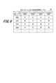
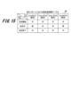
- FIG. 12 is a table configuration diagram of the ECU priority information table 24 in a sensor failure state according to the second embodiment.
- the horizontal axis indicates the failed sensor
- the vertical axis indicates the driving pattern as the vehicle state.
- the sensor state determination unit 72 determines that the sensor has failed, it refers to the ECU priority information table 24 to determine the priority of which ZoneECU based on the current vehicle state. Decide whether to raise
- the integrated ECU 20 raises the priority of the ZoneECU 1 connected to the sensor 1 and the ZoneECU 4 connected to the sensor 3 . Therefore, the integrated ECU 20 can obtain sensor information covering the recognition range of the failed sensor 2 with the recognition ranges of the sensors 1 and 3 that are not in failure. Therefore, even if any one of sensors 1, 3, 4 and 5 other than sensor 2 fails, the priority of the ZoneECU connected to the sensor that can cover the recognition range of the failed sensor is raised.
- FIG. 13 is a functional configuration diagram of a vehicle control system 1000B according to the second embodiment.
- FIG. 13 shows a configuration example of each function of the vehicle control system 1000B in the form of a data flow diagram.
- FIG. 13 briefly shows the flow of information in each part and program of the vehicle control system 1000B.
- the processing program 11A (11B, 11C, 11D) on the ZoneECU side shown in the upper part of FIG. 13 is the same as the first embodiment explained in FIG. 4, so detailed explanation is omitted.
- a processing program 21 on the integrated ECU side shown in the lower part of FIG. 13 will be described.
- the processes (11) to (16) are the same as the example of the processing program 21 on the integrated ECU side shown in the lower part of FIG.
- the processing program 21 on the integrated ECU side determines that the vehicle state has not changed based on the information received from the ZoneECUs 1 to 4, the state of the sensor is determined.
- the program 25 determines the sensor states of the sensors 1-5.
- the processing program 21 on the integrated ECU side executes the ECU priority information table 24 in the sensor state. to determine whether there is a change in the priority of ZoneECU. After that, the processing program 21 on the integrated ECU side acquires the information of the ZoneECU whose priority has been changed. Then, the processing program 21 on the integrated ECU side outputs the priority setting information to the ZoneECU whose priority is changed.
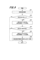
- FIG. 14 is a flowchart showing an example of processing on the integrated ECU side according to the second embodiment.
- the same step numbers are given to the same processes (S11 to S16) as the processes on the integrated ECU side according to the first embodiment shown in FIG. 9, and the description of the processes is omitted. do.
- step S12 when the vehicle state determination unit 71 determines that the vehicle state has not changed (NO in S12), the sensor state determination unit 72 checks the sensor states of the sensors connected to each ZoneECU. (S21). Then, the sensor state determination unit 72 determines whether or not a failure has occurred in the sensor (S22).
- the sensor state determination unit 72 determines that the sensor has failed (YES in S22)
- the sensor state determination unit 72 refers to the ECU priority information table 24 in the sensor failure state (S23), and determines whether the sensor has failed.
- Information of ZoneECUs connected to other sensors capable of covering the sensor recognition range (for example, information of ZoneECUs 1 and 4 when sensor 2 fails) is acquired.
- the vehicle state determination unit 71 determines whether or not there is a change in the priority of the priority information table for each ZoneECU based on the information of the ZoneECU (S14).
- the processing after step S14 is the same as the processing described above.
- step S22 determines in step S22 that no sensor failure has occurred (NO in S22), or if the vehicle state determination unit 71 determines in step S14 that the priority has not been changed. If so (NO in S14), this process ends.
- the sensor state determination unit 72 of the integrated ECU 20 checks the sensor state of the sensors connected to each ZoneECU.
- the sensor state determination unit 72 refers to the ECU priority information table 24 in the sensor failure state, and obtains information about the ZoneECU to which the redundant sensor is connected.
- the vehicle state determination unit 71 increases the priority of the ZoneECU.
- the processing program 21 on the side of the integrated ECU according to the second embodiment switches the priority of the ZoneECU according to the sensor state, thereby appropriately switching the priority information when a sensor failure occurs. It becomes possible.
- the number of sensor failures is not limited to one, and the vehicle control system 1000B according to the second embodiment can handle multiple sensor failures. If the recognition range of the faulty sensor can be covered by the recognition range of the non-faulty sensor, the integrated ECU 20 still changes the priority of the ZoneECU connected to the non-faulty sensor to a higher priority.
- the vehicle state includes left turn, right turn, and the like. However, if the priority is changed according to stages such as the initial stage, the intermediate stage, and the final stage of the left turn, the vehicle 600 can travel more safely and reliably. Therefore, vehicle control systems according to modifications of the first and second embodiments of the present invention will be described with reference to FIGS. 15 and 16.
- FIG. in the vehicle control system according to the modified example the operation of vehicle 600 is divided, and processing for changing the priority of ZoneECU for each divided operation is performed.
- the vehicle state determination unit updates the first priority information table (priority information table 22 in the driving pattern) and the second 2 By referring to the priority information table (priority information table 23 in each ZoneECU), area electronic devices (ZoneECUs 1 to 4 ) to change the priority. Specific examples are described below.
- FIG. 15 is a table configuration diagram showing an example of the priority information table 22 for driving patterns according to the third embodiment.
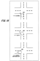
- FIG. 16 is a top view of vehicle 600 turning left at an intersection.
- three types of operation examples of changes over time ie, the start of left turn, the middle of left turn, and the end of left turn, are defined as the running pattern during left turn running (vehicle motion).
- the integrated ECU 20 determines that the vehicle 600 passes through a high-risk location based on past data
- the integrated ECU 20 connects a ZoneECU connected with a sensor capable of acquiring information around the high-risk location when the vehicle 600 passes through.
- the integrated ECU 20 may perform control such that when the vehicle 600 passes through the location, the ZoneECU connected to a sensor capable of acquiring information around the location has a higher priority.
- a plurality of types of operations are defined as the running pattern of the vehicle 600 according to the passage of time.
- the priority of the ZoneECU is defined for each operation. Therefore, the integrated ECU 20 can change the priority of the ZoneECU according to the operation of the vehicle 600 traveling in a certain traveling pattern, and acquire more detailed information.
Abstract
電子制御装置は、複数のエリア電子装置ごとに設けられ、情報を取得するエリア電子装置の優先度が設定される第1優先度情報テーブルと、車両の外部の状況から車両の状態が変化すると判断した場合に、第1優先度情報テーブルを参照し、変化する車両の状態に合わせて優先度を変更するエリア電子装置を決定し、決定したエリア電子装置に対して優先度の変更を指示し、優先度の変更を指示したエリア電子装置から優先度が高く変更された情報を得る制御部と、を備える。
Description
本発明は、電子制御装置及び車両制御システムに関する。
近年、コスト削減のため、車両を区分したエリアごとにエリア電子装置の一例としてのZoneECU(Electronic Control Unit)を配置し、ZoneECUの情報を統合ECUに情報を集約するZoneアーキテクチャと呼ばれる手法の開発が進んでいる。
自動運転システムのレベルが向上するに応じて、ZoneECUに接続されるセンサの数が増える。ZoneECUから統合ECUへは、各種の情報が優先度にしたがって送信される。例えば、制御情報は、優先度に「高」が設定され、最優先で送信される。一方、センサ情報は、優先度に「中」が設定され、エンターテインメント情報は、優先度に「低」が設定される。すなわち、ZoneECUから統合ECUには、制御情報、センサ情報、エンターテインメント情報の順に送信されていた。ところで、車両の状態によってはデータ転送の優先度を変更する必要があった。
自動運転システムのレベルが向上するに応じて、ZoneECUに接続されるセンサの数が増える。ZoneECUから統合ECUへは、各種の情報が優先度にしたがって送信される。例えば、制御情報は、優先度に「高」が設定され、最優先で送信される。一方、センサ情報は、優先度に「中」が設定され、エンターテインメント情報は、優先度に「低」が設定される。すなわち、ZoneECUから統合ECUには、制御情報、センサ情報、エンターテインメント情報の順に送信されていた。ところで、車両の状態によってはデータ転送の優先度を変更する必要があった。
従来、各種情報の優先度を設定する方法として、特許文献1に開示された方法が知られていた。この特許文献1には、「自動運転制御を行う場合において、物体が存在するか否かを確認すべき重要な周辺領域に位置する外部装置からのデータに対して高い優先度を設定することができる。」と記載されている。
しかし、上記の特許文献1に開示された方法は、外部の通信機器から得られるデータの優先度を設定するものであった。この方法では車両の状態(例えば、左折等)によって、取得したいセンサの優先度を設定できなかった。
本発明はこのような状況に鑑みて成されたものであり、車両の状態の変化に合わせてエリア電子装置の優先度を変更することを目的とする。
本発明に係る電子制御装置は、車両を区分したエリア毎に設けられる複数のエリア電子装置から取得する一又は複数の情報に基づいて、車両を制御する。この電子制御装置は、複数のエリア電子装置ごとに設けられ、情報を取得するエリア電子装置の優先度が設定される第1優先度情報テーブルと、車両の外部の状況から車両の状態が変化すると判断した場合に、第1優先度情報テーブルを参照し、変化する車両の状態に合わせて優先度を変更するエリア電子装置を決定し、決定したエリア電子装置に対して優先度の変更を指示し、優先度の変更を指示したエリア電子装置から優先度が高く変更された情報を得る制御部と、を備える。
本発明によれば、車両の状態の変化に合わせてエリア電子装置の優先度を変更するので、優先度の高いエリア電子装置から優先して情報を得ることができる。
以下、本発明を実施するための形態について、添付図面を参照して説明する。本明細書及び図面において、実質的に同一の機能又は構成を有する構成要素については、同一の符号を付することにより重複する説明を省略する。なお、以下に説明する各実施の形態は請求の範囲に係る発明を限定するものではなく、またの実施の形態の中で説明されている諸要素及びその組み合わせの全てが発明の解決手段に必須であるとは限らない。
また、以下の説明では、「プログラム」を動作主体として処理を説明する場合がある。一方、プログラムは、プロセッサ(例えば,CPU(Central Processing Unit))が実行することで、適宜の記憶資源(例えばメモリ)及び/又は通信インターフェース装置(例えばポート)を用いながら処理を行う。このため、以下に説明する処理の全体をプロセッサが行ってもよい。
プログラムを動作主体として説明する処理は、プロセッサを含む装置が行う処理としてもよい。また、プロセッサが行う処理の一部又は全部を行う専用のハードウェア回路を含んでもよい。コンピュータプログラムは、プログラムソースから装置にインストールしてもよい。プログラムソースは、例えば、プログラム配布サーバ、又は、計算機が読み取り可能な非一時的記録メディアであってもよい。
[第1の実施の形態]
図1は、第1の実施の形態に係る車両制御システムの全体構成例を示すブロック図である。
車両制御システム1000Aは、自動車などの車両600(後述する図2を参照)に搭載され、車両600の動作を制御する制御システムの一例である。車両制御システム1000Aは、各種のセンサ13A(13B、13C、13D、14A)と、エンターテインメント系情報機器16A(16B,16C,16D)と、各種アクチュエータ17A(17B、17C、17D)と、車両600の方向(例えば、左前、左後、右前、右後)などのエリアごとの制御を行う、ZoneECU10A(10B,10C,10D)とを備える。
図1は、第1の実施の形態に係る車両制御システムの全体構成例を示すブロック図である。
車両制御システム1000Aは、自動車などの車両600(後述する図2を参照)に搭載され、車両600の動作を制御する制御システムの一例である。車両制御システム1000Aは、各種のセンサ13A(13B、13C、13D、14A)と、エンターテインメント系情報機器16A(16B,16C,16D)と、各種アクチュエータ17A(17B、17C、17D)と、車両600の方向(例えば、左前、左後、右前、右後)などのエリアごとの制御を行う、ZoneECU10A(10B,10C,10D)とを備える。
また、車両制御システム1000Aは、ZoneECU10A(10B,10C,10D)のデータを集約し、車両外部にある物体の認識・その物体の認知・車両の動作判断、車両の走行制御を行う統合ECU20を備える。この電子制御装置(統合ECU20)は、車両(車両600)を区分したエリア毎に設けられる複数のエリア電子装置(ZoneECU1~4)から取得する一又は複数の情報に基づいて、車両(車両600)を制御することが可能である。
図中では、エンターテインメント系情報機器16A(16B,16C,16D)を、「ENT系」と略記する。エンターテインメント系情報機器16A(16B,16C,16D)がZoneECU10A(10B,10C,10D)に送信するエンターテインメント情報として、例えば、車両600に搭載された不図示のカーナビゲーションシステムから取得する車両600の現在位置を示す情報等がある。
以下の説明では、センサ13A、14A、13B、13C、13Dを、それぞれセンサ1,2,3,4,5又はセンサ1~5と呼ぶ。センサ1~5を区別しない場合、「センサ」のみで呼ぶことがある。センサ1~5は、Radar(Radio Detection and Ranging)、LiDAR(Light/Laser Imaging Detection and Ranging),カメラなどの車両600の周辺環境の情報を取り込むために用いられる。センサ1~5は、各センサが取得可能な情報を、センサが接続されるZoneECU1~4のいずれかに出力する。
また、以下の説明では、ZoneECU10A(10B,10C,10D)を、それぞれZoneECU1,2,3,4又はZoneECU1~4と呼ぶ。ただし、ZoneECU1~4を区別しない場合、「ZoneECU」のみで呼ぶことがある。ZoneECUは、エリア電子装置の一例として用いられる。ZoneECU1~4は、車両内のエリア(方向)に配置される。ZoneECU1~4に配置するセンサは、それぞれのエリア(方向)を認識可能であり最適な箇所に配置する。
センサ1~5と、エンターテインメント系情報機器16A(16B,16C,16D)と、各種アクチュエータ17A(17B、17C、17D)と、ZoneECU1~4と、統合ECU20とは、車載ネットワーク30A(30B、30C、30D)、及び車載ネットワーク40A(40B、40C、40D)を介して通信可能に構成されている。
車載ネットワーク30A(30B、30C、30D)及び車載ネットワーク40A(40B、40C、40D)は、例えば、Ethernet(登録商標)、CAN-FD(CAN with Flexible Data-Rate)等の任意の通信ネットワークで構成される。
ZoneECU1~4は、それぞれCPU55A(55B、55C、55D)と、メモリ50A(50B、50C、50D)とを含む。CPU55A(55B、55C、55D)は、メモリ50A(50B、50C、50D)に格納されるプログラムを読み出し、このプログラムに従って各処理を実行する。
メモリ50A(50B、50C、50D)は、例えば、RAM(Random Access Memory)及びROM(Read Only Memory)で構成される。メモリ50A(50B、50C、50D)は、CPU55A(55B、55C、55D)が実行するZoneECU側の処理プログラム11A(11B、11C、11D)と、ZoneECUの処理に必要な情報とを記憶する。ZoneECUの処理に必要な情報とは、例えば、ZoneECU1~4が統合ECU20へデータ送信する際に参照する優先度情報テーブル12A(12B、12C、12D)等である。優先度情報テーブル12A(12B、12C、12D)の詳細な構成例は、後述する図5にて説明する。
そして、ZoneECUのCPU55A(55B、55C、55D)がメモリ50A(50B,50C,50D)から読み出したZoneECU側の処理プログラム11A(11B、11C、11D)を実行することで優先度設定部15A(15B,15C,15D)の機能を実現可能である。優先度設定部15A(15B,15C,15D)は、統合ECU20から入力される優先度設定情報に基づいて、優先度情報テーブル12A(12B、12C、12D)の優先度を変更する。
統合ECU20は、CPU70と、メモリ60とを含む。CPU70は、メモリ60に格納するプログラムに従って各処理を実行する。例えば、CPU70は、本実施の形態に係る制御部の一例として用いられる。この制御部は、車両(車両600)の外部の状況から車両(車両600)の状態が変化すると判断した場合に、第1優先度情報テーブル(走行パターンにおける優先度情報テーブル22)を参照し、変化する車両(車両600)の状態に合わせて優先度を変更するエリア電子装置(ZoneECU1~4)を決定し、決定したエリア電子装置(ZoneECU1~4)に対して優先度の変更を指示し、優先度の変更を指示したエリア電子装置(ZoneECU1~4)から優先度が高く変更された情報を得る。
メモリ60は、例えば、RAM及びROMで構成されており、CPU70が実行する統合ECU側の処理プログラム21と、統合ECU20の処理に必要な情報とを記憶する。統合ECU20の必要な情報とは、例えば、車両600の走行パターンにおけるZoneECU1~4の優先度情報テーブル22や、各ZoneECU1~4における優先度情報テーブル23に格納される情報である。ここで、第1優先度情報テーブル(走行パターンにおける優先度情報テーブル22)は、複数のエリア電子装置(ZoneECU1~4)ごとに設けられ、情報を取得するエリア電子装置(ZoneECU1~4)の優先度が設定される。また、第2優先度情報テーブル(各ZoneECUにおける優先度情報テーブル23)は、エリア電子装置(ZoneECU1~4)が送信する情報の種類ごとに、車両(車両600)の状態と、エリア電子装置(ZoneECU1~4)が送信する情報の優先度との関係を規定する。
そして、統合ECU20のCPU70がメモリ60から読み出した統合ECU側の処理プログラム21を実行することで車両状態判断部71の機能を実現可能である。制御部(CPU70)が有する車両状態判断部(車両状態判断部71)は、外部の状況に基づいて車両(車両600)の状態の変化を判断し、車両(車両600)の状態が変化する前の第2優先度情報テーブル(各ZoneECUにおける優先度情報テーブル23)に規定される優先度が、車両(車両600)の状態が変化した後の第2優先度情報テーブル(各ZoneECUにおける優先度情報テーブル23)に規定される優先度と異なる場合に、優先度を変更するエリア電子装置(ZoneECU1~4)を決定し、決定したエリア電子装置(ZoneECU1~4)に優先度の変更を指示する。このため、車両状態判断部71は、ZoneECU1~4から取得した各種のデータに基づいて、車両600の状態を車両状態として判断し、車両600の走行パターンを認識することができる。
各種エンターテインメント系情報機器16A(16B、16C、16D)は、ナビゲーション情報や、音楽情報など、車両600の走行制御に必要ではない情報機器である。
各種アクチュエータ17A(17B、17C、17D)は、車両600のドライバが操作する不図示のアクセル、ブレーキ、ステアリング等に応じて、該当する機器の動作を制御する1つ以上のアクチュエータを含む。各種アクチュエータ17A(17B、17C、17D)は、統合ECU20から入力される制御情報に基づいて、車両600に搭載される走行に関わる機器の動作を制御する。さらに、各種アクチュエータ17A(17B、17C、17D)は、現在の車両600の制御状態を示す車両制御情報を統合ECU20へ通知する。統合ECU20は、各種アクチュエータ17A(17B、17C、17D)から通知された車両制御情報に基づいて、加減速、ステアリングの微調整等の制御情報を各種アクチュエータ17A(17B、17C、17D)に指示することが可能である。
なお、以降の説明では、便宜的にプログラムを動作主体として説明することもあるが、実際の実行主体は、プログラムを実行するCPU55A(55B、55C、55D、70)である。
また、統合ECU20は、CPU70に加えて、各種情報処理が可能な演算素子、例えばFPGA(Field-Programmable Gate Array)等を有することもできる。また統合ECU20は、メモリ60としてRAMやROM以外にも、例えばHDD(Hard Disk Drive)などの磁気記憶媒体、SSD(Solid State Drive)などの半導体記憶媒体を有することもできる。これらの磁気記憶媒体、半導体記憶媒体に各種のプログラム、パラメータ等を記憶してもよい。
また、統合ECU20は、CPU70に加えて、各種情報処理が可能な演算素子、例えばFPGA(Field-Programmable Gate Array)等を有することもできる。また統合ECU20は、メモリ60としてRAMやROM以外にも、例えばHDD(Hard Disk Drive)などの磁気記憶媒体、SSD(Solid State Drive)などの半導体記憶媒体を有することもできる。これらの磁気記憶媒体、半導体記憶媒体に各種のプログラム、パラメータ等を記憶してもよい。
次に、第1の実施の形態で使用する環境構成を説明する。
図2は、第1の実施の形態に係る車両600における、センサ1~5、ZoneECU1~4及び統合ECU20の配置例を示す概要図である。
図2は、第1の実施の形態に係る車両600における、センサ1~5、ZoneECU1~4及び統合ECU20の配置例を示す概要図である。
センサ(センサ1~5)の配置位置は、車両(車両600)の前方右、前方左、後方右、後方左のいずれかを含む。例えば、車両600の前方真ん中にはセンサ1が設置され、前方左にはセンサ2が設置され、後方左にはセンサ3が設置され、前方右にはセンサ4が設置され、後方右にはセンサ5が設置されている。そして、車両600は、少なくとも4つのエリアに区分されている。例えば、車両600の前方左、後方左、前方右、後方右がエリアとして区分されている。そして、エリア毎にZoneECU1~4が設けられている。
複数のエリア電子装置(ZoneECU1~4)は、車両(車両600)に配置されるセンサ(センサ1~5)の配置位置の近傍にそれぞれ配置される。
例えば、センサ1,2は、車両600の前方左に設けられたZoneECU1に接続されている。
センサ3は、車両600の後方左に設けられたZoneECU4に接続されている。
センサ4は、車両600の前方右に設けられたZoneECU2に接続されている。
センサ5は、車両600の後方右に設けられたZoneECU3に接続されている。
そして、ZoneECU1~4は、車両600の真ん中付近に配置された統合ECU20に接続されている。
例えば、センサ1,2は、車両600の前方左に設けられたZoneECU1に接続されている。
センサ3は、車両600の後方左に設けられたZoneECU4に接続されている。
センサ4は、車両600の前方右に設けられたZoneECU2に接続されている。
センサ5は、車両600の後方右に設けられたZoneECU3に接続されている。
そして、ZoneECU1~4は、車両600の真ん中付近に配置された統合ECU20に接続されている。
図3は、車両600が左折している状況を上面視した例を示す図である。
ここでは、車両600が交差点700で左折走行する時の走行パターンの例を示している。
ここでは、車両600が交差点700で左折走行する時の走行パターンの例を示している。
本実施の形態では、車両600の走行パターンが予め規定されている。そして、走行パターンに応じて、ZoneECUの優先度が変化する。例えば、車両600が左折する走行パターンでは、車両600の左側のエリアに配置されたZoneECU1,4(図2を参照)の優先度が他のZoneECU2,3より高くなる。このため、統合ECU20は、ZoneECU1,4から情報を優先して取得し、この情報に基づいて処理を実行する。
図4は、第1の実施の形態に係る車両制御システム1000Aの機能構成図である。図4では、車両制御システム1000Aの各機能の構成例をデータフローダイアグラム形式で記載している。この図4は、状態遷移図、又は状態機械図とも呼ばれる形式で記載されており、車両制御システム1000Aの各部とプログラムにおける情報の流れが簡潔に示されている。車両状態判断部(車両状態判断部71)は、車両(車両600)の状態と、車両(車両600)の状態の遷移とを規定する状態機械に基づいて、外部の状況から車両(車両600)の状態を判断する。
また、優先度情報テーブルについて、後述の図5~図7を参照して説明する。車両制御システム1000Aは、ZoneECU側の優先度情報テーブル12A(12B,12C,12D)と、統合ECU側の優先度情報テーブル22,23を備える。
上述したようにZoneECU1~4、及び統合ECU20で実行されるそれぞれの処理プログラムは、CPU55A(55B、55C、55D、70)がそれぞれの処理プログラムを実行することで、本実施の形態に係る各機能を実現している。
始めに、図4の上側に示すZoneECU1~4の処理の例について説明する。
始めに、図4の上側に示すZoneECU1~4の処理の例について説明する。
ZoneECU側の処理プログラム11A(11B、11C、11D)は、ZoneECU側のCPU55A(55B、55C、55D)により下記の(1)~(8)の手順で実行される。ただし、手順(1)~(8)は、必ずしも順番に実行される必要はなく、いずれかの手順が並行して実行されたり、逆順に実行されたりすることもある。
(1)ZoneECU側の処理プログラム11A(11B、11C、11D)は、統合ECU20から制御指令値又は優先度設定情報を受付けると、各部に対して制御を行う。ここで、統合ECU20から受付ける情報は、車両600の制御指令値及び優先度設定情報のうち、少なくとも一つとしてもよい。
(2)そして、ZoneECU側の処理プログラム11A(11B、11C、11D)は、統合ECU20から受付けた情報に対応するデータを統合ECU20に返送する。このデータには、ZoneECU側の処理プログラム11A(11B、11C、11D)がアクチュエータ17A(17B、17C、17D)から受付けた車両制御情報、後述する図5に示す優先度情報テーブル12A(12B、12C、12D)を参照して決定した優先度情報、センサ1~5が検出した情報(図中では「センサ入力」と記載)、エンターテインメント系情報機器16A(16B、16C、16D)から受付けたエンターテインメント情報のいずれかが含まれる。
(3)また、ZoneECU側の処理プログラム11A(11B、11C、11D)は、統合ECU20から入力された制御指令値を、アクチュエータ17A(17B、17C、17D)に出力する。
(4)そして、アクチュエータ17A(17B、17C、17D)は、車両制御情報をZoneECU側の処理プログラム11A(11B、11C、11D)に出力する。
(4)そして、アクチュエータ17A(17B、17C、17D)は、車両制御情報をZoneECU側の処理プログラム11A(11B、11C、11D)に出力する。
(5)また、ZoneECU側の処理プログラム11A(11B、11C、11D)は、取得する情報の優先度を変更する際に、優先度情報テーブル12A(12B、12C、12D)を参照し、優先度情報テーブル12A(12B、12C、12D)の変更する優先度を決定する。
(6)そして、ZoneECU側の処理プログラム11A(11B、11C、11D)は、決定した優先度情報を取得する。
(6)そして、ZoneECU側の処理プログラム11A(11B、11C、11D)は、決定した優先度情報を取得する。
(7)また、ZoneECU側の処理プログラム11A(11B、11C、11D)には、センサ1~5が検出した情報が入力される。
(8)また、ZoneECU側の処理プログラム11A(11B、11C、11D)には、エンターテインメント系情報機器16A(16B、16C、16D)からエンターテインメント情報が入力される。
(8)また、ZoneECU側の処理プログラム11A(11B、11C、11D)には、エンターテインメント系情報機器16A(16B、16C、16D)からエンターテインメント情報が入力される。
ZoneECU側の処理プログラム11A(11B、11C、11D)が統合ECU20に出力するデータの種類は、優先度情報テーブル12A(12B,12C,12D)に格納された優先度情報により決定される。このため、ZoneECU側の処理プログラム11A(11B、11C、11D)が優先度情報テーブル12A(12B,12C,12D)の優先度情報を書き換え、優先度情報を決定すると、ZoneECU側の処理プログラム11A(11B、11C、11D)は、決定した優先度情報に従って、センサ情報や制御情報を統合ECU20へ出力する。
ここで、ZoneECU側の優先度情報テーブルについて説明する。
図5は、ZoneECU1~4毎に設けられる、現在の優先度情報テーブル12A(12B,12C,12D)のテーブル構成図である。
図5は、ZoneECU1~4毎に設けられる、現在の優先度情報テーブル12A(12B,12C,12D)のテーブル構成図である。
優先度情報テーブル12A(12B,12C,12D)は、対象のZoneECUが出力する情報の優先度が設定されたテーブルである。図1と図5に示すようにZoneECUごとに優先度情報テーブル12A(12B,12C,12D)が用意されている。そして、各ZoneECUは、統合ECU20から優先度変更情報を受信すると、優先度情報テーブル12A(12B,12C,12D)内の情報を更新する。例えば、ZoneECU1が統合ECU20からセンサを「高」とする優先度変更情報を受信すると、図4に示したZoneECU側の処理プログラム11Aは、優先度情報テーブル12Aのセンサを「高」に変更する。
次に、図4の下側に示す統合ECU側の処理プログラム21の処理の例について説明する。図4の下側に示す統合ECU側の処理プログラム21の処理は、下記の(11)~(16)の手順で行われる。ただし、手順(11)~(16)は、必ずしも順番に実行される必要はなく、いずれかの手順が並行して実行されたり、逆順に実行されたりすることもある。
(11)統合ECU側の処理プログラム21は、ZoneECU1~4から情報を受け付ける。図中では、ZoneECU1~4から情報を受け付けることを「データ入力」と記載する。そして、統合ECU側の処理プログラム21は、受付けた情報を元に車両状態を判断する。
(12)この際、統合ECU側の処理プログラム21は、状態判断の結果(例えば、車両600の走行パターン)に基づいて、走行パターンにおける優先度情報テーブル22を参照する。
(13)そして、統合ECU側の処理プログラム21は、優先して情報を取得するZoneECUを決定する。
(13)そして、統合ECU側の処理プログラム21は、優先して情報を取得するZoneECUを決定する。
(14)次に、統合ECU側の処理プログラム21は、ZoneECU1~4から決定した優先するZoneECUに基づいて、このZoneECUにおける優先度情報テーブル23を参照する。
(15)そして、統合ECU側の処理プログラム21は、ZoneECUにおける優先度情報テーブル23に基づいて決定した、車両600の走行パターンに応じた、各ZoneECUにおける優先度設定情報を決定する。
(16)そして、統合ECU側の処理プログラム21は、ZoneECU1~4に対して、車両600の制御指令値又は優先度設定情報を出力する。なお、統合ECU側の処理プログラム21がZoneECU1~4に出力する情報は、車両600の制御指令値及び優先度設定情報のうち、少なくとも一つとしてもよい。
(15)そして、統合ECU側の処理プログラム21は、ZoneECUにおける優先度情報テーブル23に基づいて決定した、車両600の走行パターンに応じた、各ZoneECUにおける優先度設定情報を決定する。
(16)そして、統合ECU側の処理プログラム21は、ZoneECU1~4に対して、車両600の制御指令値又は優先度設定情報を出力する。なお、統合ECU側の処理プログラム21がZoneECU1~4に出力する情報は、車両600の制御指令値及び優先度設定情報のうち、少なくとも一つとしてもよい。
ここで、統合ECU側の2種類の優先度情報テーブルについて説明する。図1と図4に示したように、統合ECU側の優先度情報テーブルとして、走行パターンにおける優先度情報テーブル22と、各ZoneECUにおける優先度情報テーブル23の2種類のテーブルが設けられている。
図6は、走行パターンにおける優先度情報テーブル22のテーブル構成図である。
統合ECU20は、走行パターンにおける優先度情報テーブル22を参照し、車両状態に基づいて、各ZoneECUの優先度を決めることが可能である。例えば、車両状態が通常(例えば、直進走行)であれば、走行パターンにおける優先度情報テーブル22の走行パターンは「通常」の時の優先度情報が用いられる。すなわち、ZoneECU1~4の優先度はいずれも「中」である。
統合ECU20は、走行パターンにおける優先度情報テーブル22を参照し、車両状態に基づいて、各ZoneECUの優先度を決めることが可能である。例えば、車両状態が通常(例えば、直進走行)であれば、走行パターンにおける優先度情報テーブル22の走行パターンは「通常」の時の優先度情報が用いられる。すなわち、ZoneECU1~4の優先度はいずれも「中」である。
ここで、車両状態、すなわち走行パターンが左折に変化したことを統合ECU側の処理プログラム21が認識すると、ZoneECU1とZoneECU4の優先度を上げる。
図7は、ZoneECUにおける優先度情報テーブル23のテーブル構成図である。
ZoneECUにおける優先度情報テーブル23は、統合ECU側の処理プログラム21が、車両状態に基づいてセンサと、エンターテインメント系と、制御データとの優先度を決定するテーブルである。図7では、ZoneECU1,2における優先度情報テーブルの例が示される。他のZoneECU3,4における優先度情報テーブルは図示を省略する。
ZoneECUにおける優先度情報テーブル23は、統合ECU側の処理プログラム21が、車両状態に基づいてセンサと、エンターテインメント系と、制御データとの優先度を決定するテーブルである。図7では、ZoneECU1,2における優先度情報テーブルの例が示される。他のZoneECU3,4における優先度情報テーブルは図示を省略する。
例えば、車両600が左折状態に入ると走行パターンが「左折」に変わる。そこで、統合ECU側の処理プログラム21は、ZoneECU1とZoneECU4における優先度情報テーブルを参照し、センサと制御データの優先度を「高」に設定する。その後、統合ECU側の処理プログラム21は、ZoneECU1~4に対して、センサと制御データの優先度を「高」に設定変更した優先度情報を出力する。
次に、ZoneECUと統合ECU20の具体的な各処理の例について説明する。
始めに、ZoneECU側の処理について説明する。
図8は、ZoneECU側の処理の例を示すフローチャートである。ここでは、主に図1に示した優先度設定部15A(15B,15C,15D)の処理の例について説明する。
始めに、ZoneECU側の処理について説明する。
図8は、ZoneECU側の処理の例を示すフローチャートである。ここでは、主に図1に示した優先度設定部15A(15B,15C,15D)の処理の例について説明する。
ZoneECU側の処理は、例えば、統合ECU側、センサ、エンターテインメント系、又はアクチュエータから各種のデータを受け取った時に実行される。
まず、優先度設定部15A(15B,15C,15D)は、統合ECU20から各種のデータを受信すると(S1)、受信したデータを解析する。次に、優先度設定部15A(15B,15C,15D)は、解析の結果、受信したデータが、優先度設定情報であったか否かを判定する(S2)。
まず、優先度設定部15A(15B,15C,15D)は、統合ECU20から各種のデータを受信すると(S1)、受信したデータを解析する。次に、優先度設定部15A(15B,15C,15D)は、解析の結果、受信したデータが、優先度設定情報であったか否かを判定する(S2)。
解析したデータが、優先度設定情報であった場合(S2のYES)、優先度設定部15A(15B,15C,15D)は、統合ECU20から取得した優先度設定情報に基づいて優先度情報テーブル12A(12B、12C、12D)の優先度を変更し、本処理を終了する。
一方、解析したデータが、優先度設定情報ではなかった場合(S2のNO)には、そのデータは、制御指令値である。このため、優先度設定部15A(15B,15C,15D)は、アクチュエータ17A(17B,17C,17D)に受信したデータ(制御指令値)を送信し(S4)、本処理を終了する。
次に、統合ECU側の処理について説明する。
図9は、第1の実施の形態に係る統合ECU側の処理の例を示すフローチャートである。ここでは、主に車両状態判断部71(図1参照)の処理の例について説明する。
図9は、第1の実施の形態に係る統合ECU側の処理の例を示すフローチャートである。ここでは、主に車両状態判断部71(図1参照)の処理の例について説明する。
始めに、車両状態判断部71は、各ZoneECUから受信したデータを元に車両状態を確認する(S11)。そして、車両状態判断部71は、受信したデータに基づいて、車両状態に変化があったか否かを判定する(S12)。
車両状態に変化があった場合(S12のYES)、車両状態判断部71は、確認した車両状態から走行パターンを判定する。そして、車両状態判断部71は、走行パターンにおける優先度情報テーブル22を参照し(S13)、走行パターンにおける各ZoneECUの優先度を確認する。
さらに、車両状態判断部71は、走行パターンにおける各ZoneECUに基づいて、車両状態の変化に伴い、各ZoneECUの優先度に変更が発生するか否かを判定する(S14)。各ZoneECUの優先度に変更が発生した場合(S14のYES)、車両状態判断部71は、優先度を変更する対象となるZoneECU(図中では「対象ZoneECU」と表記する)における優先度情報テーブル23を参照し(S15)、このZoneECUにおける優先度設定情報を取得する。そして、車両状態判断部71は、優先度設定情報を、優先度を変更する対象となるZoneECUへ送信し(S16)、本処理を終了する。
一方、車両状態に変化がなかった場合(S12のNO)、又は優先度に変更が生じなかった場合(S14のNO)には、統合ECU側の処理プログラム21は、本処理を終了する。
以上説明した第1の実施の形態に係る車両制御システム1000Aでは、統合ECU20がZoneECUの優先度設定情報を持っており、車両状態又は車外の状態の変化に基づき認識可能な車両600の走行パターンに応じて、優先度の高いZoneECUの優先度設定情報を動的に変更する。一方で、通常時では静的に定められた優先度に応じてZoneECUが統合ECU20にデータを転送する。このように統合ECU20は、車両状態、又は車外の状態に応じて、優先度の高いZoneECUの優先度情報テーブル12A(12B、12C、12D)におけるセンサの優先度を変更することで、優先度の高いセンサ情報を早めに取得できる。
例えば、車両600が左折する時には、統合ECU20が車両600の左側に人や障害物がいないかを確認する必要があるので、車両600の左側に配置されたセンサ2,3から取得可能なセンサ情報を他のセンサ情報よりも早く得て車両600の制御に用いることができる。また、統合ECU20は、処理に要するリソースを、優先度の高いZoneECUに振り分けることができる。
[第2の実施の形態]
次に、本発明の第2の実施の形態に係る車両制御システムについて、図10~図14を参照して説明する。第2の実施の形態に係る車両制御システムでは、車両600に搭載されたセンサの一部が故障した場合に、統合ECU20は、故障したセンサの認識範囲をカバー可能な他のセンサが接続されたZoneECUの優先度を高めてセンサ情報を取得し、車両600の走行を制御するものである。
図10は、第2の実施の形態に係る車両制御システム1000Bの全体構成例を示すブロック図である。
次に、本発明の第2の実施の形態に係る車両制御システムについて、図10~図14を参照して説明する。第2の実施の形態に係る車両制御システムでは、車両600に搭載されたセンサの一部が故障した場合に、統合ECU20は、故障したセンサの認識範囲をカバー可能な他のセンサが接続されたZoneECUの優先度を高めてセンサ情報を取得し、車両600の走行を制御するものである。
図10は、第2の実施の形態に係る車両制御システム1000Bの全体構成例を示すブロック図である。
第2の実施の形態に係る車両制御システム1000Bは、第1の実施の形態に係る車両制御システム1000Aに対して、統合ECU20のメモリ60に、センサ故障状態におけるECUの優先度情報テーブル24と、センサの状態判断プログラム25を格納している。制御部(CPU70)は、複数のエリア電子装置(ZoneECU1~4)ごとに接続される外部の状況を認識するためのセンサ(センサ1~5)の状態を判断するセンサ状態判断部(センサ状態判断部72)を備える。このため、統合ECU20のCPU70がメモリ60から読み出したセンサの状態判断プログラム25を実行することでセンサ状態判断部72の機能を実現可能である。センサ状態判断部72は、ZoneECU1~4から取得した各種のデータに基づいて、センサ1~5の状態(故障有無等)をセンサ状態として判断することができる。
図11は、車両600に搭載されるセンサ1~3の認識範囲を表す図である。ここでは、図2に示したように車両600に搭載されるセンサ1~5のうち、センサ1~3の認識範囲の例が示される。
例えば、センサ1は、車両600の前方を認識範囲とし、センサ2は、車両600の左前方を認識範囲とし、センサ3は、車両600の左後方を認識範囲とすることが分かる。各センサの認識範囲は、各センサをほぼ中心とする扇形で表される。
また、図11では、センサ2の認識範囲がセンサ1及びセンサ3の認識範囲でカバー可能であることが示される。このため、センサ2が故障した場合であっても、センサ1及びセンサ3から得られる情報を、統合ECU20がZoneECU1,4を介して取得することで、車両600の走行に支障を生じさせない。そこで、車両状態判断部(車両状態判断部71)は、センサ状態判断部(センサ状態判断部72)により故障したと判断されたセンサ(センサ2)の認識範囲をカバー可能な他のセンサ(センサ1,3)が接続されるエリア電子装置(ZoneECU1~4)の優先度を高める。このようにセンサ2が故障することは一例に過ぎず、車両600では、様々な場所で複数のセンサの認識範囲が重なり合うようにセンサが冗長に構成されている。
図12は、第2の実施の形態に係るセンサの故障状態におけるECUの優先度情報テーブル24のテーブル構成図である。
ECUの優先度情報テーブル24の横軸には故障したセンサ、縦軸には車両状態として走行パターンが示されている。そして、センサ状態判断部72(図10を参照)は、センサが故障したと判断した場合、ECUの優先度情報テーブル24を参照することで、現在の車両状態に基づいて、どのZoneECUの優先度を上げるべきかを決定する。
ECUの優先度情報テーブル24の横軸には故障したセンサ、縦軸には車両状態として走行パターンが示されている。そして、センサ状態判断部72(図10を参照)は、センサが故障したと判断した場合、ECUの優先度情報テーブル24を参照することで、現在の車両状態に基づいて、どのZoneECUの優先度を上げるべきかを決定する。
例えば、センサ2が故障したまま、車両600が左折し始めると、統合ECU20は、センサ1に接続されたZoneECU1とセンサ3に接続されたZoneECU4の優先度を上げる。このため、統合ECU20は、故障したセンサ2の認識範囲を、故障していないセンサ1,3の認識範囲でカバーしたセンサ情報を得ることが可能となる。なので、センサ2以外に、センサ1,3,4,5のいずれかが故障した場合にも、故障したセンサの認識範囲をカバーできるセンサに接続されたZoneECUの優先度が上げられる。
図13は、第2の実施の形態に係る車両制御システム1000Bの機能構成図である。図13では、車両制御システム1000Bの各機能の構成例をデータフローダイアグラム形式で記載している。図13では、車両制御システム1000Bの各部とプログラムにおける情報の流れが簡潔に示されている。
図13の上側に示すZoneECU側の処理プログラム11A(11B、11C、11D)は、図4で説明した第1の実施の形態と同じであるため、詳細な説明を省略する。
図13の下側に示す統合ECU側の処理プログラム21について説明する。
なお、図13の下側に示す情報の流れのうち、(11)~(16)における処理については、図4の下側に示す統合ECU側の処理プログラム21の処理の例と同じである。
なお、図13の下側に示す情報の流れのうち、(11)~(16)における処理については、図4の下側に示す統合ECU側の処理プログラム21の処理の例と同じである。
(21)統合ECU側の処理プログラム21(図1に示した車両状態判断部71)がZoneECU1~4から受付けた情報に基づいて、車両状態が変化していないと判定した場合、センサの状態判断プログラム25(図10に示したセンサ状態判断部72)は、各センサ1~5のセンサ状態を判断する。
(22)そして、センサの状態判断プログラム25がセンサ1~5のいずれかに故障が発生していると判断した場合、統合ECU側の処理プログラム21は、センサ状態におけるECUの優先度情報テーブル24を参照して、ZoneECUの優先度に変更があるか否かを判定する。その後、統合ECU側の処理プログラム21は、優先度に変更があるZoneECUの情報を取得する。そして、統合ECU側の処理プログラム21は、優先度に変更があるZoneECUに対して、優先度設定情報を出力する。
(22)そして、センサの状態判断プログラム25がセンサ1~5のいずれかに故障が発生していると判断した場合、統合ECU側の処理プログラム21は、センサ状態におけるECUの優先度情報テーブル24を参照して、ZoneECUの優先度に変更があるか否かを判定する。その後、統合ECU側の処理プログラム21は、優先度に変更があるZoneECUの情報を取得する。そして、統合ECU側の処理プログラム21は、優先度に変更があるZoneECUに対して、優先度設定情報を出力する。
図14は、第2の実施の形態に係る統合ECU側の処理の例を示すフローチャートである。なお、図14においては、図9に示した第1の実施の形態に係る統合ECU側の処理と同様の処理(S11~S16)については、同一のステップ番号を付して処理の説明を省略する。
ステップS12の処理にて、車両状態判断部71が車両状態に変化が生じなかったと判定した場合(S12のNO)、センサ状態判断部72は、各ZoneECUに接続されるセンサのセンサ状態を確認する(S21)。そして、センサ状態判断部72は、センサに故障が発生したか否かを判断する(S22)。
センサ状態判断部72がセンサに故障が発生したと判断した場合(S22のYES)、センサ状態判断部72は、センサの故障状態におけるECUの優先度情報テーブル24を参照し(S23)、故障したセンサの認識範囲をカバーできる他のセンサが接続されたZoneECUの情報(例えば、センサ2が故障した場合における、ZoneECU1,4の情報)を取得する。その後、車両状態判断部71は、ZoneECUの情報に基づいて、各ZoneECUにおける優先度情報テーブルの優先度に変更があるか否かを判断する(S14)。ステップS14以降の処理は上述した処理と同様である。
ステップS22にてセンサ状態判断部72がセンサに故障が発生していないと判断した場合(S22のNO)、又はステップS14にて車両状態判断部71が優先度の変更が発生していないと判断した場合(S14のNO)には、本処理を終了する。
ここで、第2の実施の形態に係る車両制御システム1000Bの、第1の実施の形態に係る車両制御システム1000Aに対する違いについて説明する。
車両状態に変化がない場合、統合ECU20のセンサ状態判断部72により、各ZoneECUに接続されたセンサのセンサ状態が確認される。センサに故障が発生した場合、センサ状態判断部72は、センサの故障状態におけるECUの優先度情報テーブル24を参照し、冗長するセンサが接続されるZoneECUの情報を取得する。そして、車両状態判断部71は、センサ状態判断部72が取得したZoneECUの情報に基づいて、このZoneECUの優先度を高く変更する。このように、第2の実施形態に係る統合ECU側の処理プログラム21は、センサ状態に応じて、ZoneECUの優先度を切り替えることで、センサの故障発生時における優先度情報を適切に切り替えることが可能となる。
車両状態に変化がない場合、統合ECU20のセンサ状態判断部72により、各ZoneECUに接続されたセンサのセンサ状態が確認される。センサに故障が発生した場合、センサ状態判断部72は、センサの故障状態におけるECUの優先度情報テーブル24を参照し、冗長するセンサが接続されるZoneECUの情報を取得する。そして、車両状態判断部71は、センサ状態判断部72が取得したZoneECUの情報に基づいて、このZoneECUの優先度を高く変更する。このように、第2の実施形態に係る統合ECU側の処理プログラム21は、センサ状態に応じて、ZoneECUの優先度を切り替えることで、センサの故障発生時における優先度情報を適切に切り替えることが可能となる。
なお、センサの故障数は1台に限らず、複数のセンサが故障した場合であっても第2の実施の形態に係る車両制御システム1000Bが対応できる。故障したセンサの認識範囲を、故障していないセンサの認識範囲でカバーできるのであれば、統合ECU20は、故障していないセンサに接続されたZoneECUの優先度を高く変更することに変わりない。
[変形例]
車両状態には、左折や右折などが含まれる。ただし、左折の中でも、初期段階、中間段階、終了段階など段階によって優先度が変更すれば、車両600の走行がより安全かつ確実に行われるようになる。そこで、本発明の第1及び第2の実施の形態の変形例に係る車両制御システムについて、図15と図16を参照して説明する。変形例に係る車両制御システムでは、車両600の動作を分割し、その分割した動作ごとにZoneECUの優先度を変更する処理が行われる。
車両状態には、左折や右折などが含まれる。ただし、左折の中でも、初期段階、中間段階、終了段階など段階によって優先度が変更すれば、車両600の走行がより安全かつ確実に行われるようになる。そこで、本発明の第1及び第2の実施の形態の変形例に係る車両制御システムについて、図15と図16を参照して説明する。変形例に係る車両制御システムでは、車両600の動作を分割し、その分割した動作ごとにZoneECUの優先度を変更する処理が行われる。
車両状態判断部(車両状態判断部71)は、車両(車両600)の状態の変化が開始する時刻から終了する時刻にかけて、第1優先度情報テーブル(走行パターンにおける優先度情報テーブル22)及び第2優先度情報テーブル(各ZoneECUにおける優先度情報テーブル23)を参照し、車両(車両600)の状態の変化に含まれる車両(車両600)の動作の経時変化ごとにエリア電子装置(ZoneECU1~4)に対して優先度の変更を指示する。以下に具体例を説明する。
図15は、第3の実施の形態に係る走行パターンにおける優先度情報テーブル22の例を示すテーブル構成図である。
図16は、車両600が交差点を左折走行する様子を上面視した図である。
ここでは、走行パターンとして、車両600の左折走行(車両の動作)における、左折開始、左折中、左折終了の3種類の経時変化の動作例が定義されているものとする。
図16は、車両600が交差点を左折走行する様子を上面視した図である。
ここでは、走行パターンとして、車両600の左折走行(車両の動作)における、左折開始、左折中、左折終了の3種類の経時変化の動作例が定義されているものとする。
(T=T0)
左折開始時には、ZoneECU1~4の優先度はいずれも「中」である。
(T=T1)
左折中には、車両600の左前方のセンサ2が接続されたZoneECU1と、左後方のセンサ3が接続されたZoneECU4の優先度が「高」に変更される。
(T=Tn)
左折終了時には、通常の状態に戻り、車両600が左方向に直進する。このため、ZoneECU1~4の優先度がいずれも「中」に戻る。
左折開始時には、ZoneECU1~4の優先度はいずれも「中」である。
(T=T1)
左折中には、車両600の左前方のセンサ2が接続されたZoneECU1と、左後方のセンサ3が接続されたZoneECU4の優先度が「高」に変更される。
(T=Tn)
左折終了時には、通常の状態に戻り、車両600が左方向に直進する。このため、ZoneECU1~4の優先度がいずれも「中」に戻る。
なお、統合ECU20は、過去のデータに基づいて危険度が高い場所を車両600が通過すると判定した場合、車両600の通過時に危険度が高い場所周辺の情報を取得可能なセンサが接続されたZoneECUの優先度が高くなるように制御してもよい。また、ある時間にある速度以上で走行すると危険が増すような場所(例えば、朝方の通学路)がある。この場合、統合ECU20は、その場所を車両600が通過する時に、その場所周辺の情報を取得可能なセンサが接続されたZoneECUの優先度が高くなるように制御してもよい。
以上説明した変形例に係る車両制御システム1000A,1000Bでは、車両600の走行パターンとして、時間経過に応じた複数種類の動作が定義されている。そして、走行パターンにおける優先度情報テーブル22には、動作ごとにZoneECUの優先度の高低が規定されている。このため、統合ECU20は、ある走行パターンで走行する車両600の動作に応じてZoneECUの優先度が変更し、より詳細な情報を取得することが可能となる。
なお、本発明は上述した各実施の形態に限られるものではなく、請求の範囲に記載した本発明の要旨を逸脱しない限りその他種々の応用例、変形例を取り得ることは勿論である。
例えば、上述した各実施の形態は本発明を分かりやすく説明するために装置及びシステムの構成を詳細かつ具体的に説明したものであり、必ずしも説明した全ての構成を備えるものに限定されない。また、ここで説明した実施の形態の構成の一部を他の実施の形態の構成に置き換えることは可能であり、さらにはある実施の形態の構成に他の実施の形態の構成を加えることも可能である。また、各実施の形態の構成の一部について、他の構成の追加、削除、置換をすることも可能である。
また、制御線や情報線は説明上必要と考えられるものを示しており、製品上必ずしも全ての制御線や情報線を示しているとは限らない。実際には殆ど全ての構成が相互に接続されていると考えてもよい。
10A,10B,10C,10D…ZoneECU、11A,11B、11C、11D…処理プログラム、12A,12B、12C、12D…優先度情報テーブル、13A,13B、13C、13D、14A…センサ、15A,15B,15C,15D…優先度設定部、20…統合ECU、21…統合ECU側の処理プログラム、22…走行パターンにおける優先度情報テーブル、23…各ZoneECUにおける優先度情報テーブル、50A,50B、50C、50D…メモリ、60…メモリ、70…CPU、600…車両、1000A…車両制御システム
Claims (8)
- 車両を区分したエリア毎に設けられる複数のエリア電子装置から取得する一又は複数の情報に基づいて、前記車両を制御する電子制御装置であって、
複数の前記エリア電子装置ごとに設けられ、前記情報を取得する前記エリア電子装置の優先度が設定される第1優先度情報テーブルと、
前記車両の外部の状況から前記車両の状態が変化すると判断した場合に、前記第1優先度情報テーブルを参照し、変化する前記車両の状態に合わせて前記優先度を変更する前記エリア電子装置を決定し、決定した前記エリア電子装置に対して前記優先度の変更を指示し、前記優先度の変更を指示した前記エリア電子装置から優先度が高く変更された前記情報を得る制御部と、を備える
電子制御装置。 - 前記エリア電子装置が送信する前記情報の種類ごとに、前記車両の状態と、前記エリア電子装置が送信する前記情報の前記優先度との関係を規定する第2優先度情報テーブルを備え、
前記制御部は、前記外部の状況に基づいて前記車両の状態の変化を判断し、前記車両の状態が変化する前の前記第2優先度情報テーブルに規定される前記優先度が、前記車両の状態が変化した後の前記第2優先度情報テーブルに規定される前記優先度と異なる場合に、前記優先度を変更する前記エリア電子装置を決定し、決定した前記エリア電子装置に前記優先度の変更を指示する車両状態判断部を有する
請求項1に記載の電子制御装置。 - 前記車両状態判断部は、前記車両の状態と、前記車両の状態の遷移とを規定する状態機械に基づいて、前記外部の状況から前記車両の状態を判断する
請求項2に記載の電子制御装置。 - 前記制御部は、複数の前記エリア電子装置ごとに接続される前記外部の状況を認識するためのセンサの状態を判断するセンサ状態判断部を備え、
前記車両状態判断部は、前記センサ状態判断部により故障したと判断された前記センサの認識範囲をカバー可能な他の前記センサが接続される前記エリア電子装置の優先度を高める
請求項3に記載の電子制御装置。 - 前記車両状態判断部は、前記車両の状態の変化が開始する時刻から終了する時刻にかけて、前記第1優先度情報テーブル及び前記第2優先度情報テーブルを参照し、前記車両の状態の変化に含まれる前記車両の動作の経時変化ごとに前記エリア電子装置に対して前記優先度の変更を指示する
請求項3に記載の電子制御装置。 - 複数の前記エリア電子装置は、前記車両に配置される前記センサの配置位置の近傍にそれぞれ配置される
請求項4に記載の電子制御装置。 - 前記センサの配置位置は、前記車両の前方右、前方左、後方右、後方左のいずれかを含む
請求項6に記載の電子制御装置。 - 車両を区分したエリア毎に設けられる複数のエリア電子装置と、複数の前記エリア電子装置から取得する一又は複数の情報に基づいて、前記車両を制御する電子制御装置と、を備え、
前記電子制御装置は、
複数の前記エリア電子装置ごとに設けられ、前記情報を取得する前記エリア電子装置の優先度が設定される第1優先度情報テーブルと、
前記車両の外部の状況から前記車両の状態が変化すると判断した場合に、前記第1優先度情報テーブルを参照し、変化する前記車両の状態に合わせて前記優先度を変更する前記エリア電子装置を決定し、決定した前記エリア電子装置に対して前記優先度の変更を指示し、前記優先度の変更を指示した前記エリア電子装置から優先度が高く変更された前記情報を得る制御部と、を備える
車両制御システム。
Priority Applications (2)
| Application Number | Priority Date | Filing Date | Title |
|---|---|---|---|
| CN202180102369.1A CN117980209A (zh) | 2021-11-09 | 2021-11-09 | 电子控制装置及车辆控制系统 |
| PCT/JP2021/041130 WO2023084581A1 (ja) | 2021-11-09 | 2021-11-09 | 電子制御装置及び車両制御システム |
Applications Claiming Priority (1)
| Application Number | Priority Date | Filing Date | Title |
|---|---|---|---|
| PCT/JP2021/041130 WO2023084581A1 (ja) | 2021-11-09 | 2021-11-09 | 電子制御装置及び車両制御システム |
Publications (1)
| Publication Number | Publication Date |
|---|---|
| WO2023084581A1 true WO2023084581A1 (ja) | 2023-05-19 |
Family
ID=86335304
Family Applications (1)
| Application Number | Title | Priority Date | Filing Date |
|---|---|---|---|
| PCT/JP2021/041130 WO2023084581A1 (ja) | 2021-11-09 | 2021-11-09 | 電子制御装置及び車両制御システム |
Country Status (2)
| Country | Link |
|---|---|
| CN (1) | CN117980209A (ja) |
| WO (1) | WO2023084581A1 (ja) |
Citations (3)
| Publication number | Priority date | Publication date | Assignee | Title |
|---|---|---|---|---|
| JP2021011231A (ja) * | 2019-07-09 | 2021-02-04 | マツダ株式会社 | 車載ネットワークシステム |
| JP2021129278A (ja) * | 2020-02-17 | 2021-09-02 | 矢崎総業株式会社 | 通信システム |
| JP2021135809A (ja) * | 2020-02-27 | 2021-09-13 | マツダ株式会社 | 車載機器制御装置 |
-
2021
- 2021-11-09 WO PCT/JP2021/041130 patent/WO2023084581A1/ja active Application Filing
- 2021-11-09 CN CN202180102369.1A patent/CN117980209A/zh active Pending
Patent Citations (3)
| Publication number | Priority date | Publication date | Assignee | Title |
|---|---|---|---|---|
| JP2021011231A (ja) * | 2019-07-09 | 2021-02-04 | マツダ株式会社 | 車載ネットワークシステム |
| JP2021129278A (ja) * | 2020-02-17 | 2021-09-02 | 矢崎総業株式会社 | 通信システム |
| JP2021135809A (ja) * | 2020-02-27 | 2021-09-13 | マツダ株式会社 | 車載機器制御装置 |
Also Published As
| Publication number | Publication date |
|---|---|
| CN117980209A (zh) | 2024-05-03 |
Similar Documents
| Publication | Publication Date | Title |
|---|---|---|
| JP6611664B2 (ja) | 自動運転制御装置および自動運転制御方法 | |
| JP7430734B2 (ja) | 車両内通信システム、車両内通信方法、およびデバイス | |
| JP6388871B2 (ja) | ドライバー・アシスタント・アプリケーション用の方法 | |
| WO2020066304A1 (ja) | 車載電子制御システム | |
| JP7198056B2 (ja) | 車両制御装置及び車両制御方法 | |
| CN110168506B (zh) | 用于机动车的控制系统、机动车、用于控制机动车的方法 | |
| JP2005521182A (ja) | 制御装置の冗長アレイ | |
| CN112004730A (zh) | 车辆控制装置 | |
| KR102263955B1 (ko) | 적어도 부분 자율 자동차용 제어 시스템의 구성 | |
| JP2019185246A (ja) | 自動運転制御システム | |
| JP7089026B2 (ja) | 車両モジュールを制御する装置および方法 | |
| CN110733511B (zh) | 用于车辆的集成控制装置和方法 | |
| US20220017107A1 (en) | Electronic control device and in-vehicle device | |
| JP7211487B2 (ja) | 車両制御システム、車両の制御方法及び車両の制御プログラム | |
| JP3866536B2 (ja) | 車両の自動運転システム | |
| JP3881197B2 (ja) | 車両の自動運転システム | |
| KR101914624B1 (ko) | 자율주행시스템의 사고 예방을 위한 프로세서 및 동작 방법 | |
| US20200114905A1 (en) | Electronic Control Apparatus, Electronic Control System, and Electronic Control Method | |
| WO2023084581A1 (ja) | 電子制御装置及び車両制御システム | |
| JP3851522B2 (ja) | 車両の自動運転システム | |
| US11789730B2 (en) | Electronic control device and control method | |
| JP6918080B2 (ja) | 車載ネットワークシステム | |
| WO2023187979A1 (ja) | 演算処理装置、演算処理方法 | |
| WO2020217927A1 (ja) | 車両制御装置及びコンピュータプログラム | |
| JP6987201B1 (ja) | 車両制御装置及び車両制御方法 |
Legal Events
| Date | Code | Title | Description |
|---|---|---|---|
| 121 | Ep: the epo has been informed by wipo that ep was designated in this application |
Ref document number: 21963947 Country of ref document: EP Kind code of ref document: A1 |
|
| WWE | Wipo information: entry into national phase |
Ref document number: 2023559217 Country of ref document: JP |