WO2023079838A1 - 発電素子、発電システムおよびエンコーダ - Google Patents
発電素子、発電システムおよびエンコーダ Download PDFInfo
- Publication number
- WO2023079838A1 WO2023079838A1 PCT/JP2022/034356 JP2022034356W WO2023079838A1 WO 2023079838 A1 WO2023079838 A1 WO 2023079838A1 JP 2022034356 W JP2022034356 W JP 2022034356W WO 2023079838 A1 WO2023079838 A1 WO 2023079838A1
- Authority
- WO
- WIPO (PCT)
- Prior art keywords
- power generation
- generation element
- magnetic
- magnetic field
- winding axis
- Prior art date
- Legal status (The legal status is an assumption and is not a legal conclusion. Google has not performed a legal analysis and makes no representation as to the accuracy of the status listed.)
- Ceased
Links
Images








Classifications
-
- G—PHYSICS
- G01—MEASURING; TESTING
- G01D—MEASURING NOT SPECIALLY ADAPTED FOR A SPECIFIC VARIABLE; ARRANGEMENTS FOR MEASURING TWO OR MORE VARIABLES NOT COVERED IN A SINGLE OTHER SUBCLASS; TARIFF METERING APPARATUS; MEASURING OR TESTING NOT OTHERWISE PROVIDED FOR
- G01D5/00—Mechanical means for transferring the output of a sensing member; Means for converting the output of a sensing member to another variable where the form or nature of the sensing member does not constrain the means for converting; Transducers not specially adapted for a specific variable
- G01D5/12—Mechanical means for transferring the output of a sensing member; Means for converting the output of a sensing member to another variable where the form or nature of the sensing member does not constrain the means for converting; Transducers not specially adapted for a specific variable using electric or magnetic means
- G01D5/244—Mechanical means for transferring the output of a sensing member; Means for converting the output of a sensing member to another variable where the form or nature of the sensing member does not constrain the means for converting; Transducers not specially adapted for a specific variable using electric or magnetic means influencing characteristics of pulses or pulse trains; generating pulses or pulse trains
- G01D5/245—Mechanical means for transferring the output of a sensing member; Means for converting the output of a sensing member to another variable where the form or nature of the sensing member does not constrain the means for converting; Transducers not specially adapted for a specific variable using electric or magnetic means influencing characteristics of pulses or pulse trains; generating pulses or pulse trains using a variable number of pulses in a train
-
- H—ELECTRICITY
- H02—GENERATION; CONVERSION OR DISTRIBUTION OF ELECTRIC POWER
- H02K—DYNAMO-ELECTRIC MACHINES
- H02K11/00—Structural association of dynamo-electric machines with electric components or with devices for shielding, monitoring or protection
- H02K11/0094—Structural association with other electrical or electronic devices
-
- G—PHYSICS
- G01—MEASURING; TESTING
- G01P—MEASURING LINEAR OR ANGULAR SPEED, ACCELERATION, DECELERATION, OR SHOCK; INDICATING PRESENCE, ABSENCE, OR DIRECTION, OF MOVEMENT
- G01P3/00—Measuring linear or angular speed; Measuring differences of linear or angular speeds
- G01P3/42—Devices characterised by the use of electric or magnetic means
- G01P3/44—Devices characterised by the use of electric or magnetic means for measuring angular speed
- G01P3/48—Devices characterised by the use of electric or magnetic means for measuring angular speed by measuring frequency of generated current or voltage
- G01P3/481—Devices characterised by the use of electric or magnetic means for measuring angular speed by measuring frequency of generated current or voltage of pulse signals
- G01P3/4815—Devices characterised by the use of electric or magnetic means for measuring angular speed by measuring frequency of generated current or voltage of pulse signals using a pulse wire sensor, e.g. Wiegand wire
-
- H—ELECTRICITY
- H02—GENERATION; CONVERSION OR DISTRIBUTION OF ELECTRIC POWER
- H02K—DYNAMO-ELECTRIC MACHINES
- H02K3/00—Details of windings
- H02K3/04—Windings characterised by the conductor shape, form or construction, e.g. with bar conductors
Definitions
- the present disclosure relates to power generation elements, power generation systems and encoders, and more particularly to power generation elements, power generation systems and encoders utilizing the large Barkhausen effect.
- a power generation element using the large Barkhausen effect as described above even when the strength of the external magnetic field applied to the power generation element changes, it is required that the power generation amount does not easily decrease and that the variation in the power generation amount is small. .
- the power generation element is used in an encoder, if the amount of power generation varies greatly, the accuracy of detecting the rotation of the motor, etc., is lowered.
- the present disclosure has been made to solve such problems, and an object thereof is to provide a power generation element whose power generation amount is less likely to vary, a power generation system including the power generation element, and an encoder including the power generation system.
- a power generation element includes a magnetic member that produces a large Barkhausen effect due to changes in an external magnetic field, a coil wound around the magnetic member, and a winding of the coil. a ferrite member arranged along the axis along the coil and provided with an opening into which a part of the magnetic member is inserted, wherein the end of the ferrite member corresponds to the end of the magnetic member. located further away from the coil along the winding axis than the winding axis.
- a power generation system includes the power generation element, and a magnetic field applying unit that applies a magnetic field to the power generation element and repeatedly reverses the direction of the magnetic field applied to the power generation element. , wherein the power generating element generates power by reversing the direction of the magnetic field by the magnetic field applying section.
- An encoder includes the power generation system, and the power generation element outputs power generated by reversing the direction of the magnetic field by the magnetic field application unit.
- FIG. 1A is a cross-sectional view showing a schematic configuration of an encoder according to an embodiment
- FIG. 1B is a cross-sectional view showing a schematic configuration of the motor device using the encoder according to the embodiment.
- FIG. 2 is a top view of magnets in the encoder according to the embodiment.
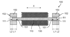
- FIG. 3 is a cross-sectional view showing a schematic configuration of the power generation element according to the embodiment.
- FIG. 4 is a plan view of a ferrite member of the power generation element according to the embodiment.
- 5 is a cross-sectional view showing a schematic configuration of a power generation element according to Comparative Example 1.
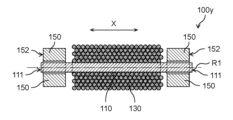
- FIG. 6 is a cross-sectional view showing a schematic configuration of a power generation element according to Comparative Example 2.
- FIG. FIG. 1A is a cross-sectional view showing a schematic configuration of an encoder according to an embodiment
- FIG. 1B is a cross-sectional view showing a schematic configuration of the motor device using the encoder according to the embodiment.
- FIG. 7 is a schematic diagram showing a circuit used for measuring the power generation amount of the power generation element.
- FIG. 8 is a diagram showing measurement results of the power generation amount of the power generation element according to Comparative Example 1.
- FIG. 9 is a diagram showing measurement results of the power generation amount of the power generation element according to the embodiment.
- FIG. 10 is a diagram showing measurement results of the power generation amount of the power generation element according to Comparative Example 2.
- FIG. 11 is a diagram showing an example of the positional relationship between the power generation element and magnets according to the embodiment.
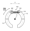
- FIG. 12 is a diagram showing another example of the positional relationship between the power generation element and magnets according to the embodiment.
- FIG. 13 is a cross-sectional view showing a schematic configuration of a power generation element according to a modification of the embodiment.
- 14 is a plan view of a ferrite member of a power generation element according to a modification of the embodiment;
- each figure is a schematic diagram and is not necessarily strictly illustrated. Therefore, scales and the like are not always the same in each drawing. Also, in each figure, the same reference numerals are assigned to substantially the same components as those in other figures, and overlapping descriptions will be omitted or simplified.
- FIG. 1A is a cross-sectional view showing a schematic configuration of an encoder 1 according to this embodiment.
- FIG. 1B is a cross-sectional view showing a schematic configuration of a motor device using encoder 1 according to the present embodiment.
- FIG. 2 is a top view of magnet 10 in encoder 1 according to the present embodiment. Note that in FIG. 1A, the magnetic member 110 and the coil 130 housed in the housing 190 of the power generating element 100 are schematically indicated by dashed lines. For ease of viewing, FIG. 2 omits illustration of the magnet 10, the rotating shaft 30, and the power generating element 100 other than the magnetic member 110 and the coil 130. As shown in FIG.
- the encoder 1 shown in FIG. 1A is, for example, a rotary encoder used in combination with a motor such as a servomotor. Further, the encoder 1 is, for example, a power-generating absolute encoder. The encoder 1 detects the rotation angle, the amount of rotation, the number of rotations, etc. of a rotating shaft 30 such as a motor based on the electric signal generated by the power generation element 100 .
- the encoder 1 includes a power generation system 5 including a magnet 10 , a rotating plate 20 , a substrate 40 and power generation elements 100 , a control circuit 50 and a memory 60 . In the encoder 1, the power generation element 100 in the power generation system 5 generates power by a change in the magnetic field formed by the magnet 10 due to the rotation of the magnet 10, and outputs the generated power as an electric signal.
- the rotating plate 20 is a plate-like member that rotates together with a rotating shaft 30, which is a driving part such as a motor.
- a central portion of one main surface of the rotating plate 20 is attached to an end portion of the rotating shaft 30 in the axial direction of the rotating shaft 30 (the direction in which the rotating shaft 30 extends).
- the rotating plate 20 extends in a direction perpendicular to the axial direction of the rotating shaft 30 .
- the rotary plate 20 rotates about a rotation axis A that passes through the center of the rotation shaft 30 and extends along the axial direction of the rotation shaft 30 .
- the rotating motion of the rotary shaft 30 is synchronized with the rotating motion of the rotating device.
- the plan view shape of the rotating plate 20 is, for example, circular.
- the rotating plate 20 is made of metal, resin, glass, ceramic, or the like, for example.
- the rotating shaft 30 has a rod shape such as a cylindrical shape.
- the axis of the rotating shaft 30 and the rotation axis A are aligned.
- the magnet 10 is an example of a magnetic field applying section that applies an external magnetic field to the power generation element 100 .
- the magnet 10 repeatedly reverses the direction of the magnetic field applied to the power generation element 100 .
- the magnet 10 is, for example, a plate-shaped magnet.
- the magnet 10 faces the substrate 40 and is arranged on the main surface of the rotating plate 20 opposite to the rotating shaft 30 .
- a pair of magnets 10 are provided on the same main surface of rotating plate 20 .
- the thickness direction of the rotating plate 20 and the thickness direction of the magnet 10 are the same, and are along the axis of the rotating shaft 30 .
- the pair of magnets 10 rotate together with the rotating plate 20 about the rotating shaft 30 (that is, about the rotating axis A).
- the rotation of the rotating shaft 30 rotates the pair of magnets 10 , thereby changing the relative positional relationship between the pair of magnets 10 and the power generation element 100 , and the magnetic field from the pair of magnets 10 applied to the power generation element 100 . also change.
- the rotation directions of the pair of magnets 10 are, for example, both clockwise and counterclockwise, but may be either clockwise or counterclockwise.
- the pair of magnets 10 sandwich the rotation axis A of the rotation shaft 30 and are arranged side by side with a gap on the same main surface of the rotation plate 20 . That is, the rotation axis A of the rotation shaft 30 is positioned between the pair of magnets 10 to form a space. Also, the pair of magnets 10 are arranged symmetrically with the rotation axis A interposed therebetween. The pair of magnets 10 have the same shape.
- Each of the pair of magnets 10 is arranged along the rotation direction of the rotating shaft 30 .
- Each of the pair of magnets 10 has an arc shape along the rotation direction of the rotating shaft 30 when viewed from above. Note that only one of the pair of magnets 10 may be provided on the main surface of the rotating plate 20 .
- the magnet 10 may be a magnet having other shapes such as a doughnut-shaped, disk-shaped, or bar-shaped magnet as long as it can change the magnetic field applied to the power generating element 100 .
- the magnet 10 is, for example, a permanent magnet, but may be an electromagnet.
- the north and south poles of the pair of magnets 10 are aligned along the direction in which the pair of magnets 10 are aligned.
- the arrangement order of the S poles and the N poles of each of the pair of magnets 10 is the same. That is, each of the pair of magnets 10 is magnetized in the direction in which the pair of magnets 10 are arranged. Therefore, each of the pair of magnets 10 generates a magnetic field along the direction in which the pair of magnets 10 are arranged.
- the magnetic pole facing the rotation axis A in one magnet 10 is the S pole
- the magnetic pole facing the rotation axis A in the other magnet 10 is the N pole. Therefore, when the pair of magnets 10 are rotated by the rotation of the rotating shaft 30 and the positions of the pair of magnets 10 are switched, the directions of the magnetic fields formed by the pair of magnets 10 are reversed. As the pair of magnets 10 rotates, the magnetic field applied to the power generating element 100 changes. Specifically, the direction of the magnetic field applied to the power generation element 100 is repeatedly reversed by rotating the pair of magnets 10 .
- the substrate 40 is positioned to face the rotating plate 20 and the magnet 10 with a gap therebetween. That is, along the axial direction of the rotating shaft 30, the rotating shaft 30, the rotating plate 20, the magnets 10, and the substrate 40 are arranged in this order. Substrate 40 does not rotate with magnet 10 and rotating plate 20 .
- the substrate 40 has a plate shape whose thickness direction is the axial direction of the rotating shaft 30 .
- the plan view shape of the substrate 40 is, for example, circular. For example, when viewed from the axial direction of the rotating shaft 30, the respective centers of the rotating shaft 30, the rotating plate 20, and the substrate 40 are aligned with each other and are at the position of the rotation axis A. As shown in FIG.
- the substrate 40 is, for example, a wiring substrate on which electronic components such as the power generating element 100, the control circuit 50 and the memory 60 are mounted.
- the control circuit 50 and the memory 60 are mounted on the main surface of the substrate 40 facing the magnet 10
- the power generation element 100 is mounted on the main surface of the substrate 40 facing away from the magnet 10. It is
- the substrate 40 is fixed to, for example, a case 71 forming a part of the encoder 1, the motor 70, or the like.
- the power generation element 100 is located on the main surface of the substrate 40 facing away from the magnet 10 . Therefore, the substrate 40 side as viewed from the power generation element 100 is the magnet 10 side.
- the power generating element 100 is aligned with the magnet 10 and the rotating plate 20 along the axial direction of the rotating shaft 30 .
- the direction indicated by the arrow Z in which the magnet 10, the rotor plate 20, and the power generation element 100 are aligned may be referred to as the "alignment direction.”
- the alignment direction is also the axial direction of rotating shaft 30 and the normal direction of main surface 11 of magnet 10 .
- the power generation element 100 does not rotate together with the magnet 10 and the rotating plate 20 .
- the power generating element 100 is provided so as to face the rotating plate 20 in the axial direction of the rotating shaft 30 .
- the power generation element 100 is arranged at a position that does not overlap the rotation axis A and is offset from the rotation axis A when viewed from the axial direction of the rotation shaft 30 .
- the power generating element 100 overlaps a position through which the magnet 10 passes when it rotates when viewed from the axial direction of the rotating shaft 30 .
- the power generation element 100 extends along the main surface of the substrate 40 so as to extend in the tangential direction of the rotation direction of the magnet 10 .
- the power generating element 100 generates power by changing the magnetic field formed by the magnet 10 due to the rotation of the magnet 10, specifically by reversing the direction of the magnetic field, and outputs the generated power.
- the winding axis direction of the coil 130 of the power generation element 100 (longitudinal direction of the magnetic member 110) is the direction in which the power generation element 100 extends.
- the winding axis direction of the coil 130 is the direction indicated by the arrow X in the drawing. Henceforth, the winding axial direction of the coil 130 shown by the arrow X in a figure may only be called "winding axial direction.”
- the power generation element 100 includes, for example, a magnetic member 110, a coil 130, a ferrite member 150 (see FIG. 3; not shown in FIGS. 1A and 2), terminals 181 and 182, and a housing 190.
- the magnetic member 110 is a magnetic member that produces a large Barkhausen effect, and a power generation pulse is generated in a coil 130 wound around the magnetic member 110 .
- the arrangement of the power generation element 100 is not particularly limited, and the power generation element 100 is positioned in a region to which the magnetic field generated by the magnet 10 is applied, and the reversal of the direction of the magnetic field caused by the rotation of the rotating shaft 30 generates a power generation pulse. should be arranged so as to generate
- the terminals 181 and 182 are members for electrically connecting the power generation element 100 and the substrate 40 .
- the terminals 181 and 182 are located near the end facing the substrate 40 in the power generating element 100 .
- the magnet 10 is arranged in the direction of the terminals 181 and 182 when viewed from the power generation element 100 .
- the terminal 181 is electrically connected to one end of the conductor wire forming the coil 130, and the terminal 182 is electrically connected to the other end of the conductor wire. That is, coil 130 and substrate 40 are electrically connected via terminals 181 and 182 .
- the housing 190 accommodates and supports the magnetic member 110, the coil 130 and the ferrite member 150. Magnetic member 110 , coil 130 and ferrite member 150 are embedded in resin or the like in housing 190 , for example. Further, the housing 190 accommodates some of the terminals 181 and 182 .
- the housing 190 is open on the magnet 10 side of the power generating element 100, for example.
- the housing 190 is fixed to the substrate 40 by, for example, a fixing member (not shown) or the like.
- the control circuit 50 is located on the main surface of the substrate 40 facing the magnet 10 .
- the control circuit 50 is electrically connected to the power generation element 100 .
- the control circuit 50 acquires electrical signals such as power generation pulses generated by the power generation element 100, and detects (calculates) the rotation angle, rotation amount, rotation speed, etc. of the rotating shaft 30 such as a motor based on the acquired electrical signals. do.
- the control circuit 50 is, for example, an IC (integrated circuit) package or the like.
- the memory 60 is located on the main surface of the substrate 40 facing the magnet 10 .
- the memory 60 is connected with the control circuit 50 .
- the memory 60 is a nonvolatile memory such as a semiconductor memory that stores the results detected by the control circuit 50 .
- FIG. 3 is a cross-sectional view showing a schematic configuration of the power generating element 100 according to this embodiment.
- FIG. 3 shows a cross section cut along the alignment direction so as to pass through the winding axis R1 of the coil 130.
- the terminals 181, 182 and housing 190 are omitted in FIG. These are the same in the drawings of each power generating element described below.
- the power generation element 100 includes a magnetic member 110, a coil 130, and a ferrite member 150.
- the magnetic member 110 is a magnetic member that produces a large Barkhausen effect due to changes in the external magnetic field formed by the magnet 10 and the like.
- the magnetic member 110 is, for example, a composite magnetic wire, such as a Wiegand wire, which has different magnetic properties between the central portion and the outer peripheral portion in the radial direction (the direction perpendicular to the winding axis R1).
- a composite magnetic wire such as a Wiegand wire
- one of the central portion and the outer peripheral portion is a hard magnetic portion, and the other is a soft magnetic portion.
- Composite magnetic wires have magnetic properties such that the direction of magnetization changes in the soft magnetic portion when a relatively small external magnetic field is applied, while the direction of magnetization does not change in the hard magnetic portion unless a relatively large external magnetic field is applied. have.
- a relatively large external magnetic field sufficient to reverse the magnetization direction of the hard magnetic portion of the composite magnetic wire is applied in the longitudinal direction of the composite magnetic wire, the magnetization direction of the hard magnetic portion and the soft magnetic portion of the composite magnetic wire are aligned in the same direction as the magnetization direction of After that, even if the direction of the external magnetic field applied to the composite magnetic wire is reversed, the magnetization direction of the hard magnetic part and the magnetization direction of the soft magnetic part are reversed while the external magnetic field is small due to the influence of the hard magnetic part.
- the magnetic member 110 is not limited to a composite magnetic wire such as a Wiegand wire, and may be any magnetic member that produces a large Barkhausen effect by having a hard magnetic portion and a soft magnetic portion with different magnetic properties.
- the hard magnetic portion and the soft magnetic portion are arranged in a direction intersecting (for example, perpendicular to) the winding axis direction, and the hard magnetic portion and the soft magnetic portion exist so as to extend in the winding axis direction. This gives rise to the large Barkhausen effect.
- the magnetic member 110 may be a magnetic member having a structure in which thin films having different magnetic properties are laminated.
- the magnetic member 110 is, for example, a wire-shaped member extending along the winding axis of the coil 130 .
- the cross-sectional shape of the magnetic member 110 cut in the radial direction is, for example, circular or elliptical, but may be other shapes such as rectangular or polygonal.
- the length of the magnetic member 110 is longer than the length of the coil 130 in the winding axis direction.
- the coil 130 is a coil in which a conductive wire forming the coil 130 is wound around the magnetic member 110 .
- the coil 130 is wound along a winding axis R ⁇ b>1 passing through the center of the magnetic member 110 and extending in the longitudinal direction of the magnetic member 110 .
- the coil 130 is located between the two end surfaces 111 on both sides of the magnetic member 110 .
- the coil 130 is located between the two ferrite members 150 .
- Coil 130 and ferrite member 150 are spaced apart. Note that the coil 130 may be in contact with the ferrite member 150 by increasing the number of turns and extending in the winding axis direction.
- the ferrite member 150 is provided at the end of the magnetic member 110 so as to be aligned with the coil 130 along the winding axis of the coil 130 .
- two ferrite members 150 are provided on each end of the magnetic member 110 .
- the two ferrite members 150 face each other across the coil 130 and have symmetrical shapes. Although one of the two ferrite members 150 will be mainly described below, the same description applies to the other.
- FIG. 4 is a plan view of the ferrite member 150.
- FIG. FIG. 4 shows a plan view shape of the ferrite member 150 viewed from the outside along the winding axis direction.
- the ferrite member 150 is a cylindrical member having an opening 151 formed therein.
- the ferrite member 150 is, for example, a ferrite bead made of a soft magnetic material.
- the ferrite member 150 is provided to collect the magnetic flux from the magnet 10, stabilize the magnetic flux in the magnetic member 110, and the like.
- the ferrite member 150 is, for example, softer magnetic than the soft magnetic portion in the magnetic member 110 , that is, has a lower coercive force than the soft magnetic portion in the magnetic member 110 .
- the ferrite member 150 is provided with an opening 151 into which a part of the magnetic member 110 is inserted.
- the opening 151 is a through hole penetrating the ferrite member 150 along the winding axis direction. Also, the opening 151 is positioned at the center of the ferrite member 150 when viewed along the winding axis direction.
- the shape of each of the outer periphery of the ferrite member 150 and the opening 151 when viewed along the winding axis direction is circular, for example. Therefore, the ferrite member 150 is cylindrical, for example.
- the end of the magnetic member 110 in the winding axis direction is positioned inside the opening 151 and covered with the ferrite member 150 . Therefore, the outer end face 152 of the ferrite member 150 is located outside the end face 111 of the magnetic member 110 in the winding axis direction. That is, the end surface 152 is located on the opposite side of the coil 130 when viewed from the end surface 111 in the winding axis direction.
- "outside" in the direction of the winding axis means "a position farther away" from the center of the magnetic member 110 in the direction of the winding axis.
- the length L1 of the region of the ferrite member 150 located inside the end face 112 is longer than the length L2 of the region of the ferrite member 150 located outside the end face 112 .
- the area where the ferrite member 150 covers the magnetic member 110 is increased, and the power generation amount of the power generation element 100 can be stabilized.
- “inside” in the direction of the winding axis means "a position closer to the center" of the magnetic member 110 in the direction of the winding axis.
- FIG. 5 is a cross-sectional view showing a schematic configuration of a power generation element 100x according to Comparative Example 1.
- FIG. 6 is a cross-sectional view showing a schematic configuration of a power generation element 100y according to Comparative Example 2. As shown in FIG.
- the power generation element 100x according to Comparative Example 1 includes a ferrite member 150x instead of the ferrite member 150.
- the ferrite member 150x is shorter than the ferrite member 150 in the winding axis direction.
- the position of the outer end surface 152x of the ferrite member 150x in the winding axis direction is inside the position of the outer end surface of the ferrite member 150 in the winding axis direction. Therefore, the end face 152x is positioned inside the end face 111 of the magnetic member 110 in the winding axis direction. That is, the end portion of the magnetic member 110 outside the end face 152x in the winding axis direction is not covered with the ferrite member 150x.
- the ferrite member 150 is located inside the power generation element 100 in the winding axis direction.
- the end surface 152 of the ferrite member 150 is positioned inside the end surface 111 of the magnetic member 110 in the winding axis direction. Therefore, in the power generation element 100y, the end portion outside the end surface 152 of the magnetic member 110 in the winding axis direction is not covered with the ferrite member 150. As shown in FIG. 6, in the power generation element 100y according to Comparative Example 2, the ferrite member 150 is located inside the power generation element 100 in the winding axis direction. In the power generation element 100y, the end surface 152 of the ferrite member 150 is positioned inside the end surface 111 of the magnetic member 110 in the winding axis direction. Therefore, in the power generation element 100y, the end portion outside the end surface 152 of the magnetic member 110 in the winding axis direction is not covered with the ferrite member 150. As shown in FIG.
- FIG. 7 is a schematic diagram showing a circuit used for measuring the power generation amount of the power generation element.
- the power generation element and the magnet 10 are arranged so as to have the positional relationship shown in FIGS. changed repeatedly.
- the power generation element was connected to the circuit as shown in FIG. Specifically, the output of the power generation element was connected to a full-wave rectifier circuit connected to a capacitor C and a resistor R. Each time the direction of the external magnetic field was reversed, the peak of the rectified voltage V of the pulse generated by the power generation element was measured, and the power generation amount was set to (1/2) CV2 .
- the power generation amount was measured 2,500 times, and the average value and minimum value of the 2,500 power generation amounts measured were derived.
- the distance between the magnet 10 and the magnetic member 110 is -1.2 mm, -0.4 mm, +0.6 mm, +1.2 mm, +1.6 mm with respect to the reference distance assumed for stable power generation. , +2.1 mm and +2.6 mm.
- the measurement was not performed under the distance conditions of +2.1 mm and +2.6 mm. The measurement results are shown in FIGS. 8 to 10.
- FIG. 8 to 10 The measurement results are shown in FIGS. 8 to 10.
- FIG. 8 is a diagram showing the measurement results of the power generation amount of the power generation element 100x according to Comparative Example 1.
- FIG. FIG. 9 is a diagram showing measurement results of the power generation amount of the power generation element 100 according to the embodiment.
- FIG. 10 is a diagram showing the measurement results of the power generation amount of the power generation element 100y according to Comparative Example 2.
- the horizontal axis indicates the difference in distance between the magnet 10 and the magnetic member 110 with respect to the reference distance. The distance between the magnet 10 and the magnetic member 110 is longer toward the right side of the horizontal axis.
- the vertical axis indicates the power generation amount measured by the method described above.
- a reference value P1 (a two-dot chain line in FIGS. 8 to 10) was set as a reference value for the amount of power generation that enables stable detection of electrical signals.
- the power generation amount is greater than that of the power generation element 100x under the distance conditions of +1.2 mm and +1.6 mm. .
- the reason why the power generation element 100 has a wider range of applied magnetic field intensity than the power generation element 100x is considered as follows.
- a ferrite member is easier to collect magnetism than the magnetic member 110 . Therefore, the magnetic flux from the magnet 10 is more likely to gather on the ferrite member than on the magnetic member 110 . As a result, the magnetic member 110 is mainly magnetized by the magnetic field through the ferrite member.
- the end surface 111 of the magnetic member 110 is located outside the end surface 152x of the ferrite member 150x in the winding axis direction. Therefore, in the winding axis direction, the end portion of the magnetic member 110 outside the end surface 152x is difficult to magnetize, or the magnetic member 110 may and the ferrite member 150x are magnetized in the opposite direction. Therefore, the magnetic flux density of the entire magnetized magnetic member 110 is less likely to increase. As a result, when the external magnetic field applied to the power generation element 100 weakened, it is considered that the amount of power generation decreased significantly.
- the end surface 111 of the magnetic member 110 is located inside the end surface 152 of the ferrite member 150 in the winding axis direction and is covered with the ferrite member 150 . Therefore, even the ends of the magnetic member 110 are magnetized, and the magnetic flux density of the entire magnetized magnetic member 110 increases. As a result, even when the external magnetic field applied to the power generation element 100 is weakened, the amount of power generation is less likely to decrease.
- the power generation element 100y when the power generation element 100y according to Comparative Example 2 using the same ferrite member 150 as the power generation element 100 is used for power generation, the power generation element The amount of power generated was lower than 100.
- the end surface 111 of the magnetic member 110 is positioned outside the end surface 152 of the ferrite member 150 in the winding axis direction, thereby reducing the amount of power generation.
- the power generation amount of the power generation element 100y is lower than that of the power generation element 100. From this, it can be said that the difference in the amount of power generation between the power generating element 100x and the power generating element 100 according to Comparative Example 1 is not due to the difference in length in the winding axis direction between the ferrite member 150x and the ferrite member 150. That is, in the power generating element 100, the end surface 111 of the magnetic member 110 is located inside the end surface 152 of the ferrite member 150 in the winding axis direction, so that the amount of power generated is less likely to decrease and the strength of the external magnetic field changes.
- the power generation element 100 is unlikely to reduce the power generation amount, and can stably output the generated power as an electrical signal.
- 11 and 12 are diagrams showing examples of the positional relationship between the power generation element 100 and the magnet.
- 11 and 12 show diagrams of the power generation element 100 and the magnets arranged along the rotation axis A as seen from the direction along the rotation axis A, as in the encoder 1 described above. ing. 11 and 12, illustration of the magnet and the power generating element 100 other than the magnetic member 110 and the coil 130 is omitted for the sake of clarity.
- FIG. 11 shows the case where the rod-shaped magnet 10A rotates about the rotation axis A as the rotation axis.
- the magnet 10A and the power generation element 100 are arranged so as to overlap each other when viewed along the rotation axis A.
- the rotation axis A which is the rotation axis of the magnet 10A, the center of the magnet 10A, and the center M1 of the power generation element 100 are at the same position.
- the S pole and the N pole of the magnet 10A are arranged symmetrically with the rotation axis A interposed therebetween. In the case of the example shown in FIG.
- the position where the strongest magnetic field from the magnet 10A is applied in the power generation element 100 is the center M1 of the power generation element 100.
- the S pole and the N pole of the magnet 10A move on the circumference around the rotation axis A while maintaining a symmetrical positional relationship with the rotation axis A interposed therebetween.
- the position where the strongest magnetic field from the magnet 10A is applied does not move. That is, the magnetic field applied from the magnet 10A is always the strongest at the center M1 of the power generating element 100.
- the direction of the magnetic field applied from the magnet 10A is reversed at the center M1 of the power generating element 100 earlier than at the ends of the power generating element 100.
- the power generation of the power generation element 100 is greatly influenced by the magnetization of the central portion of the magnetic member 110, and by the magnetization of the ends of the magnetic member 110. becomes smaller. Therefore, the effect of magnetizing up to the ends of the magnetic member 110 to improve the power generation amount of the power generation element 100 described in the measurement result of the power generation amount described above can be achieved even in the positional relationship between the magnet 10A and the power generation element 100 shown in FIG. Although it appears, it may be small.
- FIG. 12 shows an example that is the same as the positional relationship between the power generation element 100 and the pair of magnets 10 in the encoder 1 (power generation system 5) described above. That is, when viewed along the rotation axis A, the pair of magnets 10 and the power generation element 100 are arranged away from the rotation axis A, which is the center of rotation. In the example shown in FIG. 12 , when the pair of magnets 10 rotate, the pair of arc-shaped magnets 10 move along the longitudinal direction of the power generation element 100 when viewed along the rotation axis A.
- the position of the power generating element 100 where the magnetic field from the pair of magnets 10 is most strongly applied is from one end of the power generating element 100 as indicated by the white arrow M2 when the pair of magnets 10 rotates. Move toward the center, then move from the center toward the other end. Therefore, when the pair of magnets 10 rotates, the position where the direction of the magnetic field applied from the pair of magnets 10 is reversed also moves from one end of the power generation element 100 toward the center as indicated by the white arrow M2. and then move from the center toward the other end.
- the magnetization of the ends of the magnetic members 110 has a greater effect on the power generation of the power generation element 100 than in the example shown in FIG. Therefore, the effect of increasing the power generation amount of the power generation element 100 by magnetizing even the ends of the magnetic member 110 described in the measurement results of the power generation amount described above is remarkably exhibited. That is, the pair of rotating magnets 10 as shown in FIGS. 1A and 2 moves the position at which the direction of the magnetic field to be applied is reversed from the ends of the power generating element 100 in the direction of the winding axis toward the center. In the power generation system 5, the power generation amount is particularly difficult to vary.
- FIG. 13 is a cross-sectional view showing a schematic configuration of a power generating element 200 according to this modified example.
- the power generation element 200 is used, for example, in place of the power generation element 100 of the encoder 1 described above.
- the power generation element 200 differs from the power generation element 100 in that it includes a ferrite member 250 instead of the ferrite member 150 .
- FIG. 14 is a plan view of the ferrite member 250.
- FIG. FIG. 14 shows a plan view shape of the ferrite member 250 viewed from the outside along the winding axis direction.
- the ferrite member 250 includes a body portion 255 and a protrusion 256 that is thinner than the body portion 255 and extends outward from the body portion 255 along the winding axis direction. have.
- the main body portion 255 and the projection portion 256 are names given to two parts formed by processing one member made of the same material, for example.
- the ferrite member 250 may be formed by connecting a main body portion 255 and a projection portion 256 which are made of different members.
- the ferrite member 250 is provided with an opening 251 that penetrates the main body 255 and the protrusion 256 along the winding axis direction.
- the opening 251 opens on the coil 130 side of the main body 255 .
- the opening 251 is positioned at the center of the main body 255 and the protrusion 256 when viewed along the winding axis direction. Note that the opening 251 may be provided at least in the body portion 255 of the ferrite member 250 and may not be provided in the projecting portion 256 .
- the end of the magnetic member 110 in the winding axis direction is positioned inside the opening 251 and covered with the ferrite member 250 . Therefore, the outer end surface 252 of the ferrite member 250 is located outside the end surface 111 of the magnetic member 110 in the winding axis direction. In ferrite member 250 , end surface 252 is provided on protrusion 256 .
- the shape of the outer circumference of the main body 255, the outer circumference of the protrusion 256, and the opening 251 when viewed along the winding axis is, for example, circular. Therefore, the shape of each of main body portion 255 and projection portion 256 is cylindrical.
- the outer diameter of the protruding portion 256 is smaller than the outer diameter of the main body portion 255 .
- the length of the main body portion 255 is longer than the length of the projection portion 256 in the winding axis direction, for example.
- the main body portion 255 which is thicker than the protruding portion 256, becomes larger, and the magnetism-collecting force of the ferrite member 250 can be enhanced.
- the body part 255 is located entirely inside the end face 111 of the magnetic member 110 in, for example, the winding axis direction. A portion of the body portion 255 may be located outside the end face 111 of the magnetic member 110 in the winding axis direction.
- the projecting portion 256 protrudes from the end portion of the cylindrical body portion 255 outward in the winding axial direction to form a step.
- a side surface of the protrusion 256 extends in a direction parallel to the winding axis direction.
- the side surface of the protrusion 256 may be tapered with respect to the winding axis direction. That is, the projecting portion 256 may have a shape in which the distal end side is tapered.
- the ferrite member 250 has a thin protrusion 256 that protrudes outward in the winding axis direction.
- This allows, for example, protrusions 256 to penetrate into the resin that embeds magnetic member 110, coil 130 and ferrite member 250, or, if housing 190 is provided with recesses or holes, recesses.
- the protrusion 256 can be fitted into the hole. Therefore, the composite of the magnetic member 110, the coil 130, and the ferrite member 250 can be easily supported and fixed to the housing 190, and the packaging property of the power generation element 200 can be improved.
- the opening of the ferrite member is a through hole, but it is not limited to this.
- the opening of the ferrite member may be a bottomed hole that is open only on the inner side in the direction of the winding axis. That is, part of the ferrite member may also be arranged outside the end surface of the magnetic member.
- the position of the power generating element is fixed, and the magnet rotates as the rotating shaft rotates, so that the direction of the magnetic field applied to the power generating element is repeatedly reversed, but the present invention is not limited to this.
- the direction of the magnetic field applied to the power generation element may be repeatedly reversed by fixing the position of the magnet and rotating the power generation element with the rotation of the rotating shaft.
- a rotary encoder used in combination with a motor has been described as an example, but the present invention is not limited to this.
- the technology of the present disclosure can also be applied to linear encoders.
- the power generation element, power generation system, and encoder according to the present disclosure are useful for rotating or linearly moving equipment and devices such as motors.
Landscapes
- Engineering & Computer Science (AREA)
- Power Engineering (AREA)
- Physics & Mathematics (AREA)
- General Physics & Mathematics (AREA)
- Permanent Magnet Type Synchronous Machine (AREA)
Priority Applications (4)
| Application Number | Priority Date | Filing Date | Title |
|---|---|---|---|
| DE112022005254.6T DE112022005254T5 (de) | 2021-11-02 | 2022-09-14 | Energieerzeugungselement, energieerzeugungssystem und encoder |
| CN202280070561.1A CN118235018A (zh) | 2021-11-02 | 2022-09-14 | 发电元件、发电系统以及编码器 |
| JP2023557641A JPWO2023079838A1 (https=) | 2021-11-02 | 2022-09-14 | |
| US18/701,636 US20250132641A1 (en) | 2021-11-02 | 2022-09-14 | Power generation element, power generation system, and encoder |
Applications Claiming Priority (2)
| Application Number | Priority Date | Filing Date | Title |
|---|---|---|---|
| JP2021-179211 | 2021-11-02 | ||
| JP2021179211 | 2021-11-02 |
Publications (1)
| Publication Number | Publication Date |
|---|---|
| WO2023079838A1 true WO2023079838A1 (ja) | 2023-05-11 |
Family
ID=86241266
Family Applications (1)
| Application Number | Title | Priority Date | Filing Date |
|---|---|---|---|
| PCT/JP2022/034356 Ceased WO2023079838A1 (ja) | 2021-11-02 | 2022-09-14 | 発電素子、発電システムおよびエンコーダ |
Country Status (5)
| Country | Link |
|---|---|
| US (1) | US20250132641A1 (https=) |
| JP (1) | JPWO2023079838A1 (https=) |
| CN (1) | CN118235018A (https=) |
| DE (1) | DE112022005254T5 (https=) |
| WO (1) | WO2023079838A1 (https=) |
Cited By (1)
| Publication number | Priority date | Publication date | Assignee | Title |
|---|---|---|---|---|
| WO2025158490A1 (ja) * | 2024-01-22 | 2025-07-31 | 三菱電機株式会社 | 発電モジュール、発電装置、及び環境センサ |
Citations (2)
| Publication number | Priority date | Publication date | Assignee | Title |
|---|---|---|---|---|
| JP2006073974A (ja) * | 2004-09-03 | 2006-03-16 | Taiji Takemura | 磁気センサ |
| JP2021021706A (ja) * | 2019-07-30 | 2021-02-18 | オリエンタルモーター株式会社 | 回転検出装置 |
-
2022
- 2022-09-14 DE DE112022005254.6T patent/DE112022005254T5/de active Pending
- 2022-09-14 CN CN202280070561.1A patent/CN118235018A/zh active Pending
- 2022-09-14 JP JP2023557641A patent/JPWO2023079838A1/ja active Pending
- 2022-09-14 US US18/701,636 patent/US20250132641A1/en active Pending
- 2022-09-14 WO PCT/JP2022/034356 patent/WO2023079838A1/ja not_active Ceased
Patent Citations (2)
| Publication number | Priority date | Publication date | Assignee | Title |
|---|---|---|---|---|
| JP2006073974A (ja) * | 2004-09-03 | 2006-03-16 | Taiji Takemura | 磁気センサ |
| JP2021021706A (ja) * | 2019-07-30 | 2021-02-18 | オリエンタルモーター株式会社 | 回転検出装置 |
Cited By (1)
| Publication number | Priority date | Publication date | Assignee | Title |
|---|---|---|---|---|
| WO2025158490A1 (ja) * | 2024-01-22 | 2025-07-31 | 三菱電機株式会社 | 発電モジュール、発電装置、及び環境センサ |
Also Published As
| Publication number | Publication date |
|---|---|
| US20250132641A1 (en) | 2025-04-24 |
| CN118235018A (zh) | 2024-06-21 |
| DE112022005254T5 (de) | 2024-09-12 |
| JPWO2023079838A1 (https=) | 2023-05-11 |
Similar Documents
| Publication | Publication Date | Title |
|---|---|---|
| JP5108176B2 (ja) | 磁気感受性プローブ位置センサ | |
| CN103683681B (zh) | 马达 | |
| WO2022230651A1 (ja) | 発電素子、エンコーダおよび磁性部材の製造方法 | |
| WO2022230652A1 (ja) | 発電素子、エンコーダ、磁性部材の製造方法および信号取得方法 | |
| JP7109713B1 (ja) | 発電素子、磁気センサ、エンコーダおよびモータ | |
| US11994415B2 (en) | Encoder system for a drive | |
| JP2008180550A (ja) | 磁気センサ装置 | |
| JPWO2022230652A5 (https=) | ||
| WO2005040729A1 (ja) | 磁気式エンコーダ装置およびアクチュエータ | |
| CN113939714A (zh) | 转速检测器 | |
| WO2023079838A1 (ja) | 発電素子、発電システムおよびエンコーダ | |
| EP4549883A1 (en) | Electric power generating element, magnetic sensor, and encoder | |
| CA2593553C (en) | Aerospace movement probe | |
| US20240369379A1 (en) | Motion Detector | |
| JP7825730B2 (ja) | 発電素子、発電モジュール、回転数検出器及び発電機 | |
| WO2024202919A1 (ja) | 発電素子、発電システム、及びエンコーダ | |
| WO2024075465A1 (ja) | 発電素子、発電システムおよびエンコーダ | |
| CN117501072A (zh) | 旋转检测器 | |
| JP2003257738A (ja) | 永久磁石、永久磁石の製造方法および位置センサ | |
| CN118119825B (zh) | 转速检测器 | |
| WO2024252862A1 (ja) | 複合磁性部材、発電素子、発電システムおよびエンコーダ | |
| EP4707747A1 (en) | Motion detection device | |
| KR101551468B1 (ko) | 홀 센서가 구비된 브러시 홀더 장치 | |
| WO2024257402A1 (ja) | 発電素子、これを用いた磁気センサ及びエンコーダー | |
| JP2011095198A (ja) | 磁気エンコーダ |
Legal Events
| Date | Code | Title | Description |
|---|---|---|---|
| 121 | Ep: the epo has been informed by wipo that ep was designated in this application |
Ref document number: 22889662 Country of ref document: EP Kind code of ref document: A1 |
|
| ENP | Entry into the national phase |
Ref document number: 2023557641 Country of ref document: JP Kind code of ref document: A |
|
| WWE | Wipo information: entry into national phase |
Ref document number: 202280070561.1 Country of ref document: CN |
|
| 122 | Ep: pct application non-entry in european phase |
Ref document number: 22889662 Country of ref document: EP Kind code of ref document: A1 |
|
| WWP | Wipo information: published in national office |
Ref document number: 18701636 Country of ref document: US |