WO2023074810A1 - ショベル - Google Patents
ショベル Download PDFInfo
- Publication number
- WO2023074810A1 WO2023074810A1 PCT/JP2022/040197 JP2022040197W WO2023074810A1 WO 2023074810 A1 WO2023074810 A1 WO 2023074810A1 JP 2022040197 W JP2022040197 W JP 2022040197W WO 2023074810 A1 WO2023074810 A1 WO 2023074810A1
- Authority
- WO
- WIPO (PCT)
- Prior art keywords
- hydraulic
- valve
- control valve
- pressure
- main pump
- Prior art date
Links
Images


Classifications
-
- E—FIXED CONSTRUCTIONS
- E02—HYDRAULIC ENGINEERING; FOUNDATIONS; SOIL SHIFTING
- E02F—DREDGING; SOIL-SHIFTING
- E02F9/00—Component parts of dredgers or soil-shifting machines, not restricted to one of the kinds covered by groups E02F3/00 - E02F7/00
- E02F9/20—Drives; Control devices
- E02F9/22—Hydraulic or pneumatic drives
-
- F—MECHANICAL ENGINEERING; LIGHTING; HEATING; WEAPONS; BLASTING
- F15—FLUID-PRESSURE ACTUATORS; HYDRAULICS OR PNEUMATICS IN GENERAL
- F15B—SYSTEMS ACTING BY MEANS OF FLUIDS IN GENERAL; FLUID-PRESSURE ACTUATORS, e.g. SERVOMOTORS; DETAILS OF FLUID-PRESSURE SYSTEMS, NOT OTHERWISE PROVIDED FOR
- F15B11/00—Servomotor systems without provision for follow-up action; Circuits therefor
- F15B11/02—Systems essentially incorporating special features for controlling the speed or actuating force of an output member
Definitions
- This disclosure relates to excavators.
- An excavator includes a lower traveling body, an upper revolving body rotatably mounted on the lower traveling body, an attachment including a boom, an arm, and a bucket attached to the upper revolving body, A control valve capable of merging hydraulic oil discharged from each of a plurality of hydraulic pumps; The control valve is operated when at least two of the arm and the bucket are operating simultaneously.
- the excavator described above can reduce the pressure loss that can occur when a combined operation is performed to move at least two of the boom cylinder, arm cylinder, and bucket cylinder.
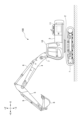
- FIG. 1 is a side view of a shovel according to an embodiment of the present invention
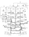
- FIG. 2 is a schematic diagram showing a configuration example of a drive system mounted on the excavator of FIG. 1
- FIG. FIG. 4 is a diagram showing the state of the drive system when the excavator is running
- FIG. 5 is a diagram showing the state of the drive system when the excavator is turning while traveling
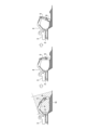
- It is a figure explaining the flow of plowing work.
- 6 is a flow chart showing a flow of an example of pressure loss suppression processing
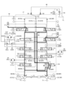
- Fig. 3 shows the state of the drive system when a plowing operation is taking place;
- FIG. 1 is a side view of a shovel 100.
- FIG. An upper revolving body 3 is rotatably mounted on a lower traveling body 1 of the excavator 100 shown in FIG. 1 through a revolving mechanism 2 .
- a boom 4 is attached to the upper swing body 3 as a working element.
- An arm 5 as a working element is attached to the tip of the boom 4
- a bucket 6 as a working element and an end attachment is attached to the tip of the arm 5 .
- the boom 4, arm 5, and bucket 6 constitute an excavation attachment, which is an example of an attachment.
- Boom 4 is driven by boom cylinder 7
- arm 5 is driven by arm cylinder 8
- bucket 6 is driven by bucket cylinder 9 .
- the upper swing body 3 is provided with a cabin 10 and is equipped with a power source such as an engine 11 .
- FIG. 2 is a diagram showing a configuration example of a drive system mounted on the excavator 100 of FIG.
- the mechanical power transmission lines are shown with double lines
- the hydraulic lines are shown with solid lines
- the pilot lines are shown with dashed lines
- the electrical control lines are shown with dashed lines.
- the excavator 100 drive system mainly includes an engine 11, a pump regulator 13, a main pump 14, a pilot pump 15, an operation device 26, a discharge pressure sensor 28, an operation sensor 29, a controller 30, and the like.
- the engine 11 is an example of a drive source for the shovel 100.
- the drive source may be an electric motor, a fuel cell, a hydrogen engine, or the like.
- the engine 11 is a diesel engine that operates to maintain a predetermined number of revolutions.
- An output shaft of the engine 11 is connected to respective input shafts of the main pump 14 and the pilot pump 15 .
- the main pump 14 is an example of a hydraulic pump, and is configured to supply hydraulic oil to the control valve unit 17.
- the main pump 14 is a swash plate type variable displacement hydraulic pump, and includes a left main pump 14L and a right main pump 14R.
- the pump regulator 13 is configured to control the discharge amount of the main pump 14 .
- the pump regulator 13 adjusts the tilt angle of the swash plate of the main pump 14 according to a command from the controller 30 to control the discharge amount of the main pump 14 .
- the pump regulator 13 may output information regarding the swash plate tilt angle to the controller 30 .
- the pump regulator 13 includes a left pump regulator 13L that controls the discharge amount of the left main pump 14L, and a right pump regulator 13R that controls the discharge amount of the right main pump 14R.
- the pilot pump 15 is configured to supply hydraulic fluid to various hydraulic devices including the operating device 26.
- the pilot pump 15 is a fixed displacement hydraulic pump.
- the pilot pump 15 may be omitted.
- the function previously performed by the pilot pump 15 may be realized by the main pump 14 .
- the main pump 14 has a function of supplying hydraulic oil to the operating device 26 and the like after reducing the pressure of the hydraulic oil by means of a throttle or the like, in addition to the function of supplying the hydraulic oil to the control valve unit 17 . good too.
- the control valve unit 17 is configured to operably accommodate a plurality of control valves.
- the control valve unit 17 includes a plurality of control valves that control the flow of hydraulic oil discharged by the main pump 14 .
- the control valve unit 17 is configured to selectively supply hydraulic fluid discharged by the main pump 14 to one or more hydraulic actuators through these control valves.
- a plurality of control valves control the flow rate of hydraulic fluid flowing from the main pump 14 to the hydraulic actuator and the flow rate of hydraulic fluid flowing from the hydraulic actuator to the hydraulic fluid tank T1.
- the hydraulic actuators include boom cylinder 7 , arm cylinder 8 , bucket cylinder 9 , travel hydraulic motor 20 , and turning hydraulic motor 21 .
- the traveling hydraulic motor 20 includes a left traveling hydraulic motor 20L and a right traveling hydraulic motor 20R.
- the revolving hydraulic motor 21 is a hydraulic motor that revolves the upper revolving body 3 .
- An oil passage 21 ⁇ /b>P connected to a port of the turning hydraulic motor 21 is connected to an oil passage 44 via a relief valve 22 and a check valve 23 .
- the oil passage 21P includes a left oil passage 21PL and a right oil passage 21PR.
- the relief valve 22 includes a left relief valve 22L and a right relief valve 22R.
- the check valve 23 includes a left check valve 23L and a right check valve 23R.
- the left relief valve 22L opens and discharges the hydraulic oil in the left oil passage 21PL to the oil passage 44 when the pressure of the hydraulic oil in the left oil passage 21PL reaches a predetermined relief pressure. Further, the right relief valve 22R opens when the pressure of the working oil in the right oil passage 21PR reaches a predetermined relief pressure, and discharges the working oil in the right oil passage 21PR to the oil passage 44.
- the left check valve 23L opens when the pressure of hydraulic oil in the left oil passage 21PL becomes lower than the pressure of hydraulic oil in the oil passage 44, and supplies hydraulic oil from the oil passage 44 to the left oil passage 21PL.
- the right check valve 23R opens when the pressure of hydraulic fluid in the right oil passage 21PR becomes lower than the pressure of hydraulic fluid in the oil passage 44, and supplies hydraulic oil from the oil passage 44 to the right oil passage 21PR.
- the operating device 26 is a device used by the operator to operate the hydraulic actuator.
- the operation device 26 is hydraulic, and supplies the hydraulic oil discharged by the pilot pump 15 to the pilot ports of the control valves corresponding to the respective hydraulic actuators via pilot lines.
- the pilot pressure which is the pressure of the hydraulic fluid supplied to each of the pilot ports, is pressure corresponding to the operation direction and amount of operation of the levers or pedals constituting the operation device 26 corresponding to each of the hydraulic actuators.
- the operating device 26 may be electric.
- the operating device 26 includes a left operating lever, a right operating lever, a left traveling lever, a right traveling lever, a left traveling operating pedal, a right traveling pedal, and the like.
- the left control lever functions as an arm control lever and a turning control lever.
- the right operating lever functions as a boom operating lever and a bucket operating lever.
- at least one of the left operating lever and the right operating lever may be referred to as an "attachment operating device”
- at least one of the left traveling lever, the right traveling lever, the left traveling pedal, and the right traveling pedal may be referred to as the " It may be referred to as a “travel operation device”.
- the left travel lever and the right travel lever are sometimes referred to as “travel levers”, and the left travel pedal and the right travel pedal are sometimes referred to as “travel pedals”. At least one of the left travel lever and left travel pedal is sometimes referred to as a “left travel operation device”, and at least one of the right travel lever and right travel pedal is referred to as a "right travel operation device”. Sometimes.
- the temperature sensor 27 is configured to detect the temperature of the hydraulic oil in the hydraulic oil tank T1 and output the detected value to the controller 30.
- the discharge pressure sensor 28 is configured to detect the discharge pressure of the main pump 14 and output the detected value to the controller 30 .
- the discharge pressure sensor 28 includes a left discharge pressure sensor 28L that detects the discharge pressure of the left main pump 14L and a right discharge pressure sensor 28R that detects the discharge pressure of the right main pump 14R.
- the operation sensor 29 is a device for detecting the content of an operator's operation using the operation device 26 .
- the operation content is, for example, an operation direction and an operation amount (operation angle).
- the operation sensor 29 is a pressure sensor that detects, in the form of pressure, the operation direction and amount of operation of the lever or pedal that constitutes the operation device 26 corresponding to each of the hydraulic actuators. Output for However, the operation content of the operation device 26 may be detected using the output of a device other than the pressure sensor, such as an operation angle sensor, acceleration sensor, angular velocity sensor, resolver, voltmeter, or ammeter.
- the controller 30 is an example of a processing circuit and functions as a control device for controlling the shovel 100.
- the controller 30 is configured by a computer including a CPU, a volatile memory device, a non-volatile memory device, and the like.
- the solenoid valve 31 is arranged in a pipeline that connects the pilot pump 15 and the pilot port of the control valve 170 in the control valve unit 17, and is configured to change the flow area of the pipeline.
- the electromagnetic valve 31 is an electromagnetic proportional control valve that operates according to a control command output by the controller 30 . Therefore, the controller 30 can supply the hydraulic oil discharged by the pilot pump 15 to the pilot port of the control valve 170 as a straight traveling valve through the solenoid valve 31 regardless of the operation of the operating device 26 by the operator.
- the controller 30 can cause the pilot pressure generated by the solenoid valve 31 to act on the pilot port of the control valve 170 .
- the center bypass oil passage 40 is a hydraulic oil line passing through control valves arranged within the control valve unit 17, and includes a left center bypass oil passage 40L and a right center bypass oil passage 40R.
- the control valve 170 is a spool valve as a straight travel valve.
- the control valve 170 essentially remains stationary when the excavator 100 is not running.
- the control valve 170 is configured to switch the flow of hydraulic oil so that the hydraulic oil is appropriately supplied from the main pump 14 to the traveling hydraulic motor 20 in order to improve the straightness of the lower traveling body 1 .
- the control valve 170 is configured to switch its valve position between a first valve position and a second valve position according to a control command from the controller 30 .
- valve position of the control valve 170 is the first valve position when only the travel operation device is operated or when only the attachment operation device is operated.
- the second valve position is when the device is operated at the same time.
- the control valve 170 remains stationary when the excavator 100 is not running, as described above. That is, the valve position of the control valve 170 is maintained at the first valve position unless the traveling operation device and the attachment operation device are operated simultaneously.
- the first valve position is a valve position that allows communication between the left main pump 14L and the left traveling hydraulic motor 20L and communication between the right main pump 14R and the right traveling hydraulic motor 20R.
- FIG. 3 shows the state of the drive system when only the traction controls are operated and the control valve 170 is switched to the first valve position. Specifically, FIG. 3 shows the state of the drive system when each of the left travel lever and the right travel lever is operated by the same amount in the forward direction. In this state, the left main pump 14L can supply hydraulic fluid to the left traveling hydraulic motor 20L, and the right main pump 14R can supply hydraulic fluid to the right traveling hydraulic motor 20R.
- FIG. 3 shows hydraulic fluid flowing from the left main pump 14L to the left traveling hydraulic motor 20L and hydraulic fluid flowing from the right main pump 14R to the right traveling hydraulic motor 20R with thick solid lines.
- the second valve position is a valve position that allows communication between the left main pump 14L and the left traveling hydraulic motor 20L and the right traveling hydraulic motor 20R, respectively.
- FIG. 4 shows the state of the drive system when the travel operating device and the attachment operating device are operated simultaneously and the control valve 170 is in the second valve position. Specifically, FIG. 4 shows a case where the left travel lever and the right travel lever are each operated in the forward direction by the same amount of operation, and the left operation lever as the turning operation lever is operated in the right turning direction. indicates the state of the drive system. In this state, the left main pump 14L can supply hydraulic fluid to each of the left travel hydraulic motor 20L and the right travel hydraulic motor 20R. For clarity, FIG. 4 shows hydraulic oil flowing from the left main pump 14L to the left traveling hydraulic motor 20L and right traveling hydraulic motor 20R, respectively, and hydraulic oil flowing from the right main pump 14R to the turning hydraulic motor 21. is represented by a thick solid line.
- control valve 170 when the control valve 170 is positioned at an intermediate valve position between the first valve position and the second valve position, the control valve 170 is configured so that the hydraulic oil discharged by the left main pump 14L and the right main pump 14R are discharged. It is configured so that it can be merged with the operating oil.
- the controller 30 outputs a control command (for example, a current command) to the solenoid valve 31 according to the operation of the operating device 26 by the operator, or regardless of the operation of the operating device 26 by the operator, to operate the pilot pump.
- a control command for example, a current command
- 15 can be supplied to a pilot port of a control valve 170 as a straight travel valve.
- the controller 30 can cause the pilot pressure generated by the solenoid valve 31 to act on the pilot port of the control valve 170 . Therefore, the controller 30 can switch the valve position of the control valve 170 between the first valve position and the second valve position at any timing.
- the control valve 171 switches the flow of hydraulic fluid in order to supply the hydraulic fluid discharged by the main pump 14 to the traveling hydraulic motor 20 and to discharge the hydraulic fluid discharged from the traveling hydraulic motor 20 to the hydraulic fluid tank. It is a spool valve. Specifically, the control valve 171 includes a control valve 171L and a control valve 171R. The control valve 171L supplies the hydraulic fluid discharged from the left main pump 14L to the left traveling hydraulic motor 20L and discharges the hydraulic fluid discharged from the left traveling hydraulic motor 20L to the hydraulic fluid tank. switch the flow.
- the control valve 171R supplies the hydraulic fluid discharged from the left main pump 14L or the right main pump 14R to the right traveling hydraulic motor 20R, and discharges the hydraulic fluid discharged from the right traveling hydraulic motor 20R to the hydraulic fluid tank. to switch the hydraulic oil flow.
- the control valve 172 supplies the hydraulic fluid discharged by the left main pump 14L to the optional hydraulic actuator, and the hydraulic fluid discharged by the optional hydraulic actuator is discharged to the hydraulic fluid tank.
- An optional hydraulic actuator is, for example, a grapple open/close cylinder.
- the control valve 173 supplies hydraulic fluid discharged by the left main pump 14L to the turning hydraulic motor 21, and controls the flow of hydraulic fluid in order to discharge the hydraulic fluid discharged by the turning hydraulic motor 21 to the hydraulic fluid tank. It is a switching spool valve.
- the control valve 174 is a spool valve for supplying the hydraulic oil discharged by the right main pump 14R to the bucket cylinder 9 and discharging the hydraulic oil in the bucket cylinder 9 to the hydraulic oil tank.
- the control valve 175 is a spool valve that switches the flow of hydraulic oil to supply the hydraulic oil discharged by the main pump 14 to the boom cylinder 7 and to discharge the hydraulic oil in the boom cylinder 7 to the hydraulic oil tank.
- the control valve 175 includes a control valve 175L and a control valve 175R.
- the control valve 175L operates only when the boom 4 is raised, and does not operate when the boom 4 is lowered.
- the control valve 176 is a spool valve that switches the flow of hydraulic fluid to supply the hydraulic fluid discharged by the main pump 14 to the arm cylinder 8 and to discharge the hydraulic fluid in the arm cylinder 8 to the hydraulic fluid tank.
- the control valve 176 includes a control valve 176L and a control valve 176R.
- control valves 170 to 176 are pilot spool valves in this embodiment, they may be electromagnetic spool valves when the operating device 26 is electric.
- the lever operation amount is input to the controller 30 as an electric signal.
- a solenoid valve is arranged between the pilot pump 15 and the pilot port of each control valve.
- the solenoid valve is configured to operate in response to an electrical signal from controller 30 .
- the controller 30 controls the solenoid valve with an electric signal corresponding to the lever operation amount to increase or decrease the pilot pressure, thereby moving each control valve.
- Each control valve may be composed of an electromagnetic spool valve as described above. In this case, the electromagnetic spool valve operates according to an electric signal from the controller 30 corresponding to the lever operation amount of the electric operation lever.
- the return oil passage 41 is a hydraulic oil line arranged within the control valve unit 17 and includes a left return oil passage 41L and a right return oil passage 41R. Hydraulic oil that has flowed out of the hydraulic actuator and passed through the control valves 171 to 176 flows through the return oil passage 41 toward the hydraulic oil tank T1.
- a parallel oil passage 42 is a hydraulic oil line parallel to the center bypass oil passage 40 .
- the parallel oil passage 42 includes a left parallel oil passage 42L parallel to the left center bypass oil passage 40L and a right parallel oil passage 42R parallel to the right center bypass oil passage 40R.
- the left parallel oil passage 42L can supply hydraulic oil to more downstream control valves when the flow of hydraulic oil through the left center bypass oil passage 40L is restricted or blocked by the control valves 171L, 172, 173, or 175L.
- the right parallel oil passage 42R can supply hydraulic oil to more downstream control valves when the flow of hydraulic oil through the right center bypass oil passage 40R is restricted or blocked by the control valves 171R, 174, or 175R.
- the throttle 60 is arranged in the right parallel oil passage 42R upstream of the control valve 176R and downstream of a branch point where the oil passage connecting the right parallel oil passage 42R and the control valve 175R branches off from the right parallel oil passage 42R. It is a fixed diaphragm provided.
- the throttle 60 includes, for example, an arm cylinder 8 with a low load pressure and a hydraulic actuator with a high load pressure (at least one of the boom cylinder 7, the bucket cylinder 9, and the right travel hydraulic motor 20R). It has a function of preventing most of the hydraulic oil discharged from the right main pump 14R from flowing into the arm cylinder 8 with a low load pressure when they are operated simultaneously.
- the throttle 60 can increase the pressure of the hydraulic fluid on the downstream side when the hydraulic fluid flows into the arm cylinder 8 through the control valve 176R. Therefore, even when the arm cylinder 8 with low load pressure and the boom cylinder 7 with high load pressure are operated at the same time, the drive system including the throttle 60 is operated not only with the arm cylinder 8 with low load pressure, but also with the boom cylinder 7 with high load pressure. Even the boom cylinder 7 with high load pressure can be reliably operated. The same applies to the case where the arm cylinder 8 with low load pressure and the bucket cylinder 9 with high load pressure or the right travel hydraulic motor 20R are operated at the same time.
- throttles 18 are arranged between each of the most downstream control valves 175 and the hydraulic oil tank T1.
- a throttle 18 restricts the flow of hydraulic oil discharged by the main pump 14 .
- the throttle 18 generates a control pressure (negative control pressure) for controlling the pump regulator 13 .
- the diaphragm 18 is a fixed diaphragm with a fixed aperture area, and includes a left diaphragm 18L and a right diaphragm 18R.
- the aperture 18 tends to increase stability against sudden changes in the control pressure as the opening area increases.
- the throttle 18 tends to increase the responsiveness of the control pressure as the opening area becomes smaller.
- the flow of hydraulic oil discharged from the left main pump 14L is restricted by the left throttle 18L.
- the left throttle 18L generates a control pressure for controlling the left pump regulator 13L.
- the flow of hydraulic fluid discharged from the right main pump 14R is restricted by the right throttle 18R.
- the right throttle 18R generates a control pressure for controlling the right pump regulator 13R.
- the control pressure sensor 19 is a sensor that detects control pressure (negative control pressure) generated upstream of the throttle 18, and includes a left control pressure sensor 19L and a right control pressure sensor 19R. In this embodiment, the control pressure sensor 19 is configured to output the detected value to the controller 30 . Controller 30 outputs a command corresponding to the control pressure to pump regulator 13 .
- the pump regulator 13 controls the discharge amount of the main pump 14 by adjusting the tilt angle of the swash plate of the main pump 14 according to the command. Specifically, the pump regulator 13 reduces the discharge amount of the main pump 14 as the control pressure increases, and increases the discharge amount of the main pump 14 as the control pressure decreases.
- the drive system of FIG. 2 can suppress wasteful energy consumption in the main pump 14 when none of the hydraulic actuators are operated. Wasteful energy consumption includes pumping loss caused by the hydraulic oil discharged by the main pump 14 in the center bypass oil passage 40 . To reliably supply necessary and sufficient working oil from a main pump 14 to a hydraulic actuator to be operated when the hydraulic actuator is operated.
- the center bypass oil passage 40 and the return oil passage 41 are connected to the junction of the oil passages 43 downstream of the throttle 18 .
- the oil passage 43 branches into two at the downstream of the confluence and is connected to the oil passages 45 and 46 outside the control valve unit 17 . That is, the hydraulic fluid flowing through the center bypass oil passage 40 and the return oil passage 41 respectively joins in the oil passage 43 and then passes through the oil passage 45 or the oil passage 46 to reach the hydraulic oil tank T1. Further, the oil passage 43 is connected to the turning hydraulic motor 21 via an oil passage 44 which is a hydraulic oil line for compensating for the shortage of hydraulic oil on the suction side of the turning hydraulic motor 21 .
- the oil passage 45 is a hydraulic oil line that connects the oil passage 43 and the hydraulic oil tank T1.
- a check valve 50 , an oil cooler 51 and a filter 53 are arranged in the oil passage 45 .
- the check valve 50 is a valve that opens when the pressure difference between the primary side and the secondary side exceeds a predetermined valve opening pressure difference.
- the check valve 50 is a spring-type check valve that opens when the pressure on the upstream side is higher than the pressure on the downstream side and the pressure difference exceeds the valve opening pressure difference. Hydraulic oil is caused to flow out toward the oil cooler 51 .
- the check valve 50 can maintain the pressure of the hydraulic oil in the oil passages 43 and 44 at a level higher than the valve opening pressure, and can reliably compensate for the shortage of hydraulic oil on the suction side of the turning hydraulic motor 21. make it In this case, the valve opening pressure is the lower limit of the back pressure for the throttle 18 .
- the back pressure on the throttle 18 increases as the flow rate of hydraulic fluid passing through the check valve 50 increases.
- the check valve 50 may be integrated with the control valve unit 17 or may be omitted. When the check valve 50 is omitted, the pressure loss in each of the oil passage 45 , check valve 50 , oil cooler 51 and filter 53 becomes back pressure to the throttle 18 . The back pressure on the throttle 18 increases as the flow rate of hydraulic fluid passing through the oil passage 45 increases.
- the oil cooler 51 is a device for cooling hydraulic oil circulating in the drive system.
- the oil cooler 51 is included in a heat exchanger unit cooled by a cooling fan driven by the engine 11 .
- the heat exchanger unit includes a radiator, an intercooler, an oil cooler 51, and the like.
- the oil passage 45 includes an oil passage portion 45a connecting the check valve 50 and the oil cooler 51, and an oil passage portion 45b connecting the oil cooler 51 and the hydraulic oil tank T1.
- a filter 53 is arranged in the oil passage portion 45b.
- the oil passage 46 is a bypass oil passage that bypasses the oil cooler 51 .
- the oil passage 46 has one end connected to the oil passage 43 and the other end connected to the hydraulic oil tank T1. One end may be connected to the oil passage 45 between the check valve 50 and the oil cooler 51 .
- a check valve 52 is arranged in the oil passage 46 .
- the check valve 52 is a valve that opens when the pressure difference between the primary side and the secondary side exceeds a predetermined valve opening pressure difference.
- the check valve 52 is a spring-type check valve that opens when the pressure on the upstream side is higher than the pressure on the downstream side and the pressure difference exceeds the valve opening pressure difference. Hydraulic oil is caused to flow out toward the hydraulic oil tank T1.
- the opening pressure difference of the check valve 52 is greater than the opening pressure difference of the check valve 50 . Therefore, the hydraulic oil in the control valve unit 17 first flows through the check valve 50, and then flows through the check valve 52 when the pressure exceeds the valve opening pressure due to resistance when flowing through the oil cooler 51.
- the check valve 52 may be integrated with the control valve unit 17 .
- the pressure loss suppression process is a process for suppressing pressure loss that occurs in the hydraulic oil line when a predetermined combined action is being performed.
- FIG. 5 is a diagram illustrating the flow of a plowing work as an example of work realized by a combined motion including an arm closing motion and a boom raising motion, which are an example of a predetermined combined motion.
- Plowing work is a work for scraping off excess undulations of the ground surface flatly.
- FIG. 6 is a flowchart showing the flow of pressure loss suppression processing. The controller 30 repeatedly executes this pressure loss suppression process at a predetermined control cycle.
- the operator places the tip of the bucket 6 on the ground to be worked within the working area N of the excavation attachment (the boom 4, the arm 5, and the bucket 6) as the working device.
- the tip of the bucket 6 is positioned so as to be at a desired height position.
- the work area N means, for example, an area reachable by the tip of the bucket 6 .
- the bucket 6 is in an open state (for example, the state of the bucket 6 when the bucket angle is 90 degrees or more).
- the bucket angle is, for example, the opening angle of the bucket 6 from the most closed state (rotational angle of the bucket 6 around the bucket pin).
- the operator starts the plowing work by closing the arm 5 while gradually raising the boom 4. Specifically, the operator executes the arm closing operation by full lever operation of the arm operation lever, and executes the boom raising operation by fine operation or half lever operation of the boom operation lever.
- Fine operation is defined as, for example, the amount of lever operation when the operation lever is in the neutral position is 0%, and the amount of lever operation when the operation lever is tilted to the maximum is 100%, and the lever is less than 20%. It means operation with manipulated variable.
- Full lever operation means, for example, operation with a lever operation amount of 80% or more.
- Half-lever operation means operation with a lever operation amount of 20% or more and less than 80%, for example.
- the fine operation and the half lever operation may be collectively referred to as "non-full lever operation".
- the operator continues the plowing work by closing the arm 5 while gradually raising the boom 4 from the state shown in the center diagram of FIG. Specifically, the operator continues the arm closing operation by full lever operation of the arm operation lever, and continues the boom raising operation by fine operation or half lever operation of the boom operation lever. As a result, excess undulations on the ground surface are scraped flat by the tip of the bucket 6 .
- the hydraulic oil discharged from the left main pump 14L passes through the left center bypass oil passage 40L and the left parallel oil passage 42L respectively, reaches the control valve 176L, and then reaches the control valve 176L. It reaches the bottom side oil chamber of the arm cylinder 8 through the control valve 176L. Also, part of the hydraulic oil discharged by the right main pump 14R reaches the control valve 176R through the right parallel oil passage 42R and then reaches the bottom side oil chamber of the arm cylinder 8 through the control valve 176R.
- Another portion of the hydraulic oil discharged by the right main pump 14R reaches the control valve 175R through the right parallel oil passage 42R and then reaches the bottom side oil chamber of the boom cylinder 7 through the control valve 175R.
- the discharge amounts of the left main pump 14L and the right main pump 14R are increased to the maximum discharge amount by negative control because the arm control lever is fully operated.
- the cross section of the right parallel oil passage 42R leading to the control valve 176R is narrowed by the throttle 60, and the pressure of the hydraulic oil on the upstream side of the throttle 60 becomes higher than the pressure of the hydraulic oil on the downstream side of the throttle 60.
- a combined action (first combined action) that includes an arm closing action achieved by fine operation or half-lever operation of the arm control lever and a boom raising action achieved by fine operation or half-lever operation of the boom control lever.
- most of the hydraulic fluid discharged from the right main pump 14R flows into the arm cylinder 8, preventing the hydraulic fluid discharged from the right main pump 14R from flowing into the boom cylinder 7. is. That is, this is to prevent the boom raising operation from slowing down even though the load is small during the combined operation.
- the hydraulic oil discharged by the right main pump 14R causes pressure loss when passing through the throttle 60.
- the pressure loss increases as the flow rate of hydraulic oil discharged from the right main pump 14R increases.
- it is achieved by a compound operation (second compound operation) including an arm closing operation achieved by full lever operation of the arm operating lever and a boom raising operation achieved by fine operation or half lever operation of the boom operating lever.
- the pressure loss generated at the throttle 60 becomes large.
- the lever operation amount of the boom operating lever in the second compound action is smaller than the lever operation amount of the boom operating lever in the first compound action.
- the opening area of the PC port (pump-cylinder port) of the control valve 175 is also smaller, so the pressure loss in the oil passage on the right main pump 14R side also increases.
- the excavator 100 reduces the pressure loss generated at the throttle 60 by executing pressure loss suppression processing when a predetermined combined motion such as a combined motion during plowing work is performed. .
- the controller 30 mounted on the excavator 100 outputs a control command to the solenoid valve 31 and exceptionally operates the control valve 170, which basically does not operate when the excavator 100 is not traveling. Reduce the pressure loss that occurs.
- the controller 30 determines whether or not a predetermined combined action is being performed (step ST1). In the illustrated example, the controller 30 determines whether or not a predetermined combined action is being performed based on the output of the operation sensor 29 .
- Predetermined combined motions include combined motions for achieving a plowing operation.
- a compound operation for realizing plowing work is, for example, a compound operation including an arm closing operation achieved by full lever operation of the arm operation lever and a boom raising operation achieved by fine operation or half lever operation of the boom operation lever. It is action.
- the controller 30 may determine whether or not a predetermined combined action is being performed based on outputs from sensors other than the operation sensor 29 .
- the controller 30 is based on the output of a boom angle sensor, an arm angle sensor, a bucket angle sensor, or the like, or based on the output of an image sensor such as a space recognition device (camera or LIDAR) mounted on the upper swing structure 3. , it may be determined whether or not a predetermined combined action is being performed.
- a boom angle sensor an arm angle sensor, a bucket angle sensor, or the like
- an image sensor such as a space recognition device (camera or LIDAR) mounted on the upper swing structure 3.
- step ST1 the controller 30 terminates the current pressure loss suppression process. This is because it is considered that the pressure loss that should be reduced does not occur in the hydraulic oil line.
- the controller 30 compares the discharge pressure P1 of the left main pump 14L and the discharge pressure P2 of the right main pump 14R (step ST2). In the illustrated example, the controller 30 determines whether or not the discharge pressure P2 of the right main pump 14R detected by the right discharge pressure sensor 28R is greater than the discharge pressure P1 of the left main pump 14L detected by the left discharge pressure sensor 28L. judge.
- step ST2 when it is determined that the discharge pressure P2 is not greater than the discharge pressure P1 (NO in step ST2), that is, when it is determined that the discharge pressure P2 is equal to or less than the discharge pressure P1, the controller 30 performs the current pressure loss suppression process. terminate. This is because it is considered that the pressure loss that should be reduced does not occur in the hydraulic oil line.
- the controller 30 when it is determined that the discharge pressure P2 is higher than the discharge pressure P1 (YES in step ST2), the controller 30 operates the control valve 170 as a straight traveling valve (step ST3).
- the controller 30 outputs a control command to the solenoid valve 31 to position the control valve 170 at an intermediate valve position between the first valve position and the second valve position.
- the discharge pressure P1 after operating the control valve 170 becomes higher than the discharge pressure P1 before operating the control valve 170, and the discharge pressure P2 after operating the control valve 170 becomes smaller than the discharge pressure P2 before operating the .
- the fact that the discharge pressure P1 and the discharge pressure P2 are the same value may include that the differential pressure between the discharge pressure P1 and the discharge pressure P2 is less than a preset predetermined value.
- FIG. 7 shows, as an example, the state of the drive system when plowing work is being performed. Specifically, FIG. 7 shows a case where the valve position of the control valve 170 is positioned at the intermediate valve position when a combined operation including a boom raising operation by half-lever operation and an arm closing operation by full-lever operation is performed. Indicates the state of the drive system. For clarity, FIG. 7 shows hydraulic oil flowing from the left main pump 14L to the bottom side oil chamber of the arm cylinder 8, and from the right main pump 14R to the bottom side oil chamber of the arm cylinder 8 and the bottom side oil of the boom cylinder 7. Hydraulic oil flowing through each of the chambers is represented by a thick solid line.
- the controller 30 performs pressure loss suppression processing, that is, by positioning the control valve 170 at the intermediate valve position when a predetermined combined action is being performed, thereby causing pressure loss generated in the hydraulic oil line to occur. It is possible to suppress the pressure loss caused by
- the excavator 100 does not destabilize the movement of the excavation attachment by providing a configuration capable of implementing pressure loss suppression processing. This is because the pressure loss suppression process is implemented in a configuration including the throttle 60 . That is, even in a configuration that can implement the pressure loss suppression process, the throttle 60 prevents the hydraulic fluid that should flow into the hydraulic actuator (boom cylinder 7) with high load pressure from flowing into the hydraulic actuator (arm cylinder 8) with low load pressure. This is because it is possible to suppress or prevent storage.
- the controller 30 determines that the discharge pressure P2 is greater than the discharge pressure P1 when the differential pressure between the discharge pressure P2, which is greater than the discharge pressure P1, and the discharge pressure P1 is equal to or greater than a predetermined value. may be configured to That is, the controller 30 is configured to determine that the discharge pressure P2 is not greater than the discharge pressure P1 if the differential pressure is less than a predetermined value even if the discharge pressure P2 is greater than the discharge pressure P1.
- the controller 30 may be configured to keep the control valve 170 in an operating state until a predetermined release condition is satisfied after the control valve 170 as the straight traveling valve is operated. good. That is, even if the discharge pressure P1 and the discharge pressure P2 become the same after the valve position of the control valve 170 is positioned at the intermediate valve position, the controller 30 keeps the control valve 170 closed until the predetermined release condition is satisfied.
- the valve position of 170 may remain positioned in the middle valve position. This is for maintaining a state in which the pressure loss is reduced.
- the predetermined cancellation condition is to determine that the predetermined combined action determined to have been performed in step ST1 is no longer being performed.
- the controller 30 determines that the combined motion including the boom raising motion and the arm closing motion determined to be performed in step ST1 is no longer being performed.
- the valve position of control valve 170 is typically switched to the first valve position.
- the controller 30 switches the valve position of the control valve 170 to the first valve position when the combined operation including the boom raising operation and the arm closing operation shifts to a single operation including only the boom raising operation.
- the controller 30 performs control as a straight travel valve when a predetermined combined action, which is a combined action including an arm closing action by full lever operation and a boom raising action by non-full lever operation, is being performed. It is configured to actuate valve 170 .
- the controller 30 can perform a compound operation including an arm closing operation by full lever operation and a boom lowering operation by non-full lever operation, a compound operation including an arm closing operation by full lever operation and a bucket closing operation by non-full lever operation, and an arm operation by full lever operation.
- control valve 170 as a straight traveling valve may be operated when another predetermined combined action such as a combined action including an opening action is performed.
- the combined operation including the arm closing operation by full lever operation and the boom raising operation by non-full lever operation performed to realize plowing work is the full lever operation performed to realize other work such as floor excavation work. It may be a combined operation including arm closing operation by non-full lever operation and boom raising operation by non-full lever operation, and arm closing operation by full lever operation and non-full lever It may be a combined action including a boom raising action by an operation.
- the excavator 100 includes, as shown in FIGS.
- a excavation attachment which is an example of an attachment, including a boom 4, an arm 5, and a bucket 6, which is attached to the revolving structure 3, and hydraulic oil discharged from each of the plurality of hydraulic pumps can be combined as a travel straight valve.
- a control valve 170 and a controller 30 as a control device capable of controlling the movement of the control valve 170 are provided.
- the controller 30 is configured to operate the control valve 170 to perform pressure loss suppression processing when at least two of the boom 4, the arm 5, and the bucket 6 are operating simultaneously during non-traveling. ing.
- FIG. A excavation attachment, which is an example of an attachment, including a boom 4, an arm 5, and a bucket 6, which is attached to the revolving structure 3, and hydraulic oil discharged from each of the plurality of hydraulic pumps can be combined as a travel straight valve.
- a control valve 170 and a controller 30 as a control device capable of controlling the movement of the control valve 170 are provided.
- the controller 30 is
- the control valve 170 as the straight travel valve is arranged between the right main pump 14R and the control valve 171R on the right center bypass oil passage 40R, and is arranged on the left parallel oil passage 42L. It is arranged between the main pump 14L and the branch point to the control valve 172 .
- the control valve 170 as a straight travel valve is basically configured such that the valve position is switched when the travel operation device is operated. It is configured so that the valve position can be switched even when it is not on.
- the control valve 170 as a straight travel valve enables the hydraulic oil discharged by the left main pump 14L to be supplied to the left parallel oil passage 42L, and allows the hydraulic oil discharged by the right main pump 14R to be supplied to the right center pump.
- a first valve position that enables supply to the bypass oil passage 40R a first valve position that allows the hydraulic oil discharged by the left main pump 14L to be supplied to the right center bypass oil passage 40R, and a hydraulic oil that is discharged by the right main pump 14R. It is configured to be able to switch between a second valve position that enables supply to the left parallel oil passage 42L.
- the control valve 170 as a straight traveling valve combines the hydraulic fluids discharged from the left main pump 14L and the right main pump at an intermediate valve position between the first valve position and the second valve position. , so that it can be supplied to each of the left parallel oil passage 42L and the right center bypass oil passage 40R.
- the arm 5, and the bucket 6 are operating simultaneously during non-traveling operation, for example, at least two of the boom 4, the arm 5, and the bucket 6 are operated simultaneously during the non-traveling operation. when it is being manipulated.
- the controller 30 may determine whether or not at least two of the boom 4, arm 5, and bucket 6 are operating at the same time based on the output of the operation sensor 29 while the vehicle is not traveling. Alternatively, the controller 30 determines whether or not at least two of the boom 4, the arm 5, and the bucket 6 are operating simultaneously based on the outputs of the boom angle sensor, the arm angle sensor, the bucket angle sensor, and the like. good too. Alternatively, the controller 30 may determine whether the excavator 100 is running based on the output of a positioning device such as GNSS.
- the controller 30 controls at least two of the boom 4, the arm 5, and the bucket 6 to move during non-traveling. It may be determined whether or not they are operating at the same time.
- an image sensor such as a space recognition device (camera or LIDAR) mounted on the upper rotating body 3
- the controller 30 controls at least two of the boom 4, the arm 5, and the bucket 6 to move during non-traveling. It may be determined whether or not they are operating at the same time.
- the above configuration has the effect of reducing the pressure loss that can occur when a combined operation for moving at least two of the boom cylinder 7, the arm cylinder 8, and the bucket cylinder 9 is performed. Bring. Therefore, the above-described configuration brings about the effect of being able to improve the fuel consumption or the operating speed of the excavation attachment.
- the above-described configuration is configured to execute pressure loss suppression processing using the existing straight travel valve (control valve 170), the fixed throttle (throttle 60) is changed to a variable throttle, or This provides the effect of reducing the pressure loss in the hydraulic oil line without adopting a relatively high-cost method such as providing an electromagnetic proportional valve in the pilot line of the control valve 176 .
- the above-described configuration is configured to execute the pressure loss suppression process using the existing straight travel valve (control valve 170), it is possible to eliminate the need to adopt a structure or configuration that requires a separate installation space. , the effect that the pressure loss in the hydraulic oil line can be reduced.
- the above-described configuration has the effect of omitting the electromagnetic proportional valve in the excavator provided with the electromagnetic proportional valve in the pilot line of the control valve 176, thereby reducing the manufacturing cost.
- the controller 30 may be configured to operate the control valve 170 as a straight travel valve when a combined motion including at least one of the arm closing motion, the boom raising motion, and the bucket closing motion is performed. .
- the controller 30 is configured to operate the control valve 170 as a straight traveling valve only when the operation amount of the arm closing operation is larger than the operation amount of the boom raising operation and the operation amount of the bucket closing operation. good too. That is, the controller 30 operates the control valve 170 when the operation amount of the arm closing operation is equal to or less than the operation amount of the boom raising operation even when a combined operation including the arm closing operation and the boom raising operation is being performed. It may be configured not to allow This is because the pressure loss generated in the hydraulic oil line is considered to be small.
- the excavator 100 has a left main pump 14L as a first hydraulic pump capable of supplying hydraulic oil to the left traveling hydraulic motor 20L and the right traveling hydraulic motor 20R, and the right traveling hydraulic motor 20R. and a right main pump 14R as a second hydraulic pump capable of supplying hydraulic oil.
- the controller 30 controls the discharge pressure of the right main pump 14R when at least two of the boom 4, the arm 5, and the bucket 6 are operating simultaneously during non-running.
- the control valve 170 as a straight traveling valve is operated to join the hydraulic oil discharged from the left main pump 14L and the hydraulic oil discharged from the right main pump 14R. It may be configured to allow
- control valve 170 as a straight travel valve communicates the left main pump 14L with the left travel hydraulic motor 20L and communicates the right main pump 14R with the right travel hydraulic motor 20R.
- the hydraulic oil discharged by the left main pump 14L and the right main pump 14R are It may be configured to merge with the hydraulic oil to be discharged.
- This configuration has the effect of reducing the pressure loss that can occur when a combined operation is being performed to move at least two of the boom cylinder 7, arm cylinder 8, and bucket cylinder 9. .
- the pressure difference between the discharge pressure P2 of the right main pump 14R and the discharge pressure P1 of the left main pump 14L the pressure of hydraulic fluid upstream of the throttle 60 and the pressure of hydraulic fluid downstream of the throttle 60 are reduced. This is because the differential pressure between and can be reduced. Therefore, this configuration has the effect of improving fuel consumption or increasing the operating speed of the drilling attachment.
- plowing work was shown, but the work to which the present invention can be applied is not limited to plowing work.
- control valve 170 is configured as a 4-port 2-chamber spool valve. Then, the controller 30 utilizes an intermediate valve position between the first valve position and the second valve position of the control valve 170 to mix the hydraulic oil discharged by the left main pump 14L and the hydraulic oil discharged by the right main pump 14R. are configured to merge.
- control valve 170 may be configured as a 4-port 3-chamber spool valve with the intermediate valve position as an independent third valve position. That is, the control valve 170 may be configured as a 4-port, 3-chamber spool valve having an independent third valve position provided with a junction connecting the left parallel oil passage 42L and the right center bypass oil passage 40R. .
- control valve 170 may be configured so that the opening area of the confluence passage connecting the left parallel oil passage 42L and the right center bypass oil passage 40R can be changed according to the stroke amount.
Abstract
ショベル(100)は、下部走行体(1)と、下部走行体(1)に搭載される上部旋回体(3)と、上部旋回体(3)に取り付けられる、ブーム(4)、アーム(5)、及びバケット(6)を含む掘削アタッチメントと、走行直進弁としての制御弁(170)と、制御弁(170)の動きを制御可能なコントローラ(30)と、を備える。コントローラ(30)は、非走行時に、ブーム(4)、アーム(5)、及びバケット(6)のうちの少なくとも二つが同時に動作しているときに、制御弁(170)を動作させる。
Description
本開示は、ショベルに関する。
従来、油圧ポンプが吐出する作動油を利用して複数の油圧アクチュエータを同時に動作させることができるように構成されたショベルが知られている(特許文献1参照。)。
しかしながら、特許文献1に開示されるようなショベルでは、二つの油圧アクチュエータを同時に動かすための複合操作が行われている場合、無駄な圧力損失が発生してしまうおそれがある。二つの油圧アクチュエータのそれぞれの負荷圧が互いに異なるためである。すなわち、負荷圧が高い油圧アクチュエータに確実に作動油が供給されるように、負荷が低い油圧アクチュエータに供給される作動油の流量を制限するための絞りが設けられているためである。
上述に鑑み、ブームシリンダ、アームシリンダ、及びバケットシリンダのうちの少なくとも二つを動かすための複合操作が行われている場合に発生し得る圧力損失を低減させることができるショベルを提供することが望ましい。
本発明の実施形態に係るショベルは、下部走行体と、前記下部走行体に旋回可能に搭載される上部旋回体と、前記上部旋回体に取り付けられる、ブーム、アーム、及びバケットを含むアタッチメントと、複数の油圧ポンプのそれぞれが吐出する作動油を合流させることができる制御弁と、前記制御弁の動きを制御可能な制御装置と、を備え、前記制御装置は、非走行時に、前記ブーム、前記アーム、及び前記バケットのうちの少なくとも二つが同時に動作しているときに、前記制御弁を動作させる。
上述のショベルは、ブームシリンダ、アームシリンダ、及びバケットシリンダのうちの少なくとも二つを動かすための複合操作が行われている場合に発生し得る圧力損失を低減させることができる。
最初に、図1を参照して、本発明の実施形態に係る建設機械としての掘削機(ショベル100)について説明する。図1はショベル100の側面図である。図1に示すショベル100の下部走行体1には旋回機構2を介して上部旋回体3が旋回可能に搭載されている。上部旋回体3には作業要素としてのブーム4が取り付けられている。ブーム4の先端には作業要素としてのアーム5が取り付けられ、アーム5の先端に作業要素及びエンドアタッチメントとしてのバケット6が取り付けられている。ブーム4、アーム5、及びバケット6は、アタッチメントの一例である掘削アタッチメントを構成している。ブーム4は、ブームシリンダ7により駆動され、アーム5は、アームシリンダ8により駆動され、バケット6は、バケットシリンダ9により駆動される。上部旋回体3には、キャビン10が設けられ、且つ、エンジン11等の動力源が搭載されている。
図2は、図1のショベル100に搭載される駆動システムの構成例を示す図である。図2では、機械的動力伝達ラインが二重線で示され、作動油ラインが実線で示され、パイロットラインが破線で示され、且つ、電気制御ラインが一点鎖線で示されている。
ショベル100の駆動システムは、主に、エンジン11、ポンプレギュレータ13、メインポンプ14、パイロットポンプ15、操作装置26、吐出圧センサ28、操作センサ29、及びコントローラ30等を含む。
エンジン11は、ショベル100の駆動源の一例である。駆動源は、電動モータ、燃料電池、又は水素エンジン等であってもよい。本実施形態では、エンジン11は、所定の回転数を維持するように動作するディーゼルエンジンである。エンジン11の出力軸は、メインポンプ14及びパイロットポンプ15のそれぞれの入力軸に連結されている。
メインポンプ14は、油圧ポンプの一例であり、作動油をコントロールバルブユニット17に供給できるように構成されている。本実施形態では、メインポンプ14は、斜板式可変容量型油圧ポンプであり、左メインポンプ14L及び右メインポンプ14Rを含む。
ポンプレギュレータ13は、メインポンプ14の吐出量を制御するように構成されている。本実施形態では、ポンプレギュレータ13は、コントローラ30からの指令に応じてメインポンプ14の斜板傾転角を調節してメインポンプ14の吐出量を制御する。ポンプレギュレータ13は、斜板傾転角に関する情報をコントローラ30に対して出力してもよい。具体的には、ポンプレギュレータ13は、左メインポンプ14Lの吐出量を制御する左ポンプレギュレータ13L、及び、右メインポンプ14Rの吐出量を制御する右ポンプレギュレータ13Rを含む。
パイロットポンプ15は、操作装置26を含む各種油圧機器に作動油を供給するように構成されている。本実施形態では、パイロットポンプ15は、固定容量型油圧ポンプである。但し、パイロットポンプ15は、省略されてもよい。この場合、パイロットポンプ15が担っていた機能は、メインポンプ14によって実現されてもよい。すなわち、メインポンプ14は、コントロールバルブユニット17に作動油を供給する機能とは別に、絞り等により作動油の圧力を低下させた後で操作装置26等に作動油を供給する機能を備えていてもよい。
コントロールバルブユニット17は、複数の制御弁を動作可能に収容するように構成されている。本実施形態では、コントロールバルブユニット17は、メインポンプ14が吐出する作動油の流れを制御する複数の制御弁を含む。コントロールバルブユニット17は、それら制御弁を通じ、メインポンプ14が吐出する作動油を1又は複数の油圧アクチュエータに選択的に供給できるように構成されている。複数の制御弁は、メインポンプ14から油圧アクチュエータに流れる作動油の流量、及び、油圧アクチュエータから作動油タンクT1に流れる作動油の流量を制御する。油圧アクチュエータは、ブームシリンダ7、アームシリンダ8、バケットシリンダ9、走行用油圧モータ20、及び旋回用油圧モータ21を含む。走行用油圧モータ20は、左走行用油圧モータ20L及び右走行用油圧モータ20Rを含む。
旋回用油圧モータ21は、上部旋回体3を旋回させる油圧モータである。旋回用油圧モータ21のポートに接続される油路21Pは、リリーフ弁22及びチェック弁23を介して油路44に接続されている。具体的には、油路21Pは、左油路21PL及び右油路21PRを含む。リリーフ弁22は、左リリーフ弁22L及び右リリーフ弁22Rを含む。チェック弁23は、左チェック弁23L及び右チェック弁23Rを含む。
左リリーフ弁22Lは、左油路21PLにおける作動油の圧力が所定のリリーフ圧に達した場合に開き、左油路21PLにおける作動油を油路44に排出する。また、右リリーフ弁22Rは、右油路21PRにおける作動油の圧力が所定のリリーフ圧に達した場合に開き、右油路21PRにおける作動油の作動油を油路44に排出する。
左チェック弁23Lは、左油路21PLにおける作動油の圧力が油路44における作動油の圧力より低くなった場合に開き、油路44から左油路21PLに作動油を補給する。右チェック弁23Rは、右油路21PRにおける作動油の圧力が油路44における作動油の圧力より低くなった場合に開き、油路44から右油路21PRに作動油を補給する。この構成により、チェック弁23は、旋回用油圧モータ21の制動時に吸い込み側ポートに作動油を補給できる。
操作装置26は、操作者が油圧アクチュエータの操作のために用いる装置である。本実施形態では、操作装置26は、油圧式であり、パイロットラインを介して、パイロットポンプ15が吐出する作動油を油圧アクチュエータのそれぞれに対応する制御弁のパイロットポートに供給する。パイロットポートのそれぞれに供給される作動油の圧力であるパイロット圧は、油圧アクチュエータのそれぞれに対応する、操作装置26を構成するレバー又はペダルの操作方向及び操作量に応じた圧力である。但し、操作装置26は電気式であってもよい。
具体的には、操作装置26は、左操作レバー、右操作レバー、左走行レバー、右走行レバー、左走行操作ペダル、及び右走行ペダル等を含む。左操作レバーは、アーム操作レバー及び旋回操作レバーとして機能する。右操作レバーは、ブーム操作レバー及びバケット操作レバーとして機能する。以下では、左操作レバー及び右操作レバーの少なくとも一つは「アタッチメント操作装置」と称される場合があり、左走行レバー、右走行レバー、左走行ペダル、及び右走行ペダルの少なくとも一つは「走行操作装置」と称される場合がある。また、左走行レバー及び右走行レバーは「走行レバー」と称される場合があり、左走行ペダル及び右走行ペダルは「走行ペダル」と称される場合がある。また、左走行レバー及び左走行ペダルの少なくとも一つは「左走行操作装置」と称される場合があり、右走行レバー及び右走行ペダルの少なくとも一つは「右走行操作装置」と称される場合がある。
温度センサ27は、作動油タンクT1における作動油の温度を検出し、検出した値をコントローラ30に対して出力するように構成されている。
吐出圧センサ28は、メインポンプ14の吐出圧を検出し、検出した値をコントローラ30に対して出力するように構成されている。本実施形態では、吐出圧センサ28は、左メインポンプ14Lの吐出圧を検出する左吐出圧センサ28L、及び、右メインポンプ14Rの吐出圧を検出する右吐出圧センサ28Rを含む。
操作センサ29は、操作装置26を用いた操作者の操作内容を検出するための装置である。操作内容は、例えば、操作方向及び操作量(操作角度)等である。本実施形態では、操作センサ29は、油圧アクチュエータのそれぞれに対応する操作装置26を構成するレバー又はペダルの操作方向及び操作量を圧力の形で検出する圧力センサであり、検出した値をコントローラ30に対して出力する。但し、操作装置26の操作内容は、操作角センサ、加速度センサ、角速度センサ、レゾルバ、電圧計、又は電流計等、圧力センサ以外の装置の出力を用いて検出されてもよい。
コントローラ30は、処理回路の一例であり、ショベル100を制御するための制御装置として機能する。本実施形態では、コントローラ30は、CPU、揮発性記憶装置、及び不揮発性記憶装置等を備えたコンピュータで構成されている。
電磁弁31は、パイロットポンプ15とコントロールバルブユニット17内の制御弁170のパイロットポートとを接続する管路に配置され、その管路の流路面積を変更できるように構成されている。本実施形態では、電磁弁31は、コントローラ30が出力する制御指令に応じて動作する電磁比例制御弁である。そのため、コントローラ30は、操作者による操作装置26の操作とは無関係に、パイロットポンプ15が吐出する作動油を、電磁弁31を介し、走行直進弁としての制御弁170のパイロットポートに供給できる。そして、コントローラ30は、電磁弁31が生成するパイロット圧を制御弁170のパイロットポートに作用させることができる。
センターバイパス油路40は、コントロールバルブユニット17内に配置された制御弁を通る作動油ラインであり、左センターバイパス油路40L及び右センターバイパス油路40Rを含む。
制御弁170は、走行直進弁としてのスプール弁である。制御弁170は、原則的にショベル100の非走行時には静止したままである。本実施形態では、制御弁170は、下部走行体1の直進性を高めるべくメインポンプ14から走行用油圧モータ20に作動油が適切に供給されるように作動油の流れを切り換えるように構成されている。具体的には、制御弁170は、コントローラ30からの制御指令に応じて第1弁位置と第2弁位置との間で弁位置が切り換わるように構成されている。
より具体的には、制御弁170の弁位置は、走行操作装置のみが操作されている場合、或いは、アタッチメント操作装置のみが操作されている場合に第1弁位置となり、走行操作装置とアタッチメント操作装置とが同時に操作されている場合に第2弁位置となる。なお、制御弁170は、上述のように、原則的にショベル100の非走行時には静止したままである。すなわち、制御弁170の弁位置は、走行操作装置とアタッチメント操作装置とが同時に操作されない限り、第1弁位置のままで維持される。
第1弁位置は、左メインポンプ14Lと左走行用油圧モータ20Lとを連通させ且つ右メインポンプ14Rと右走行用油圧モータ20Rとを連通させる弁位置である。図3は、走行操作装置のみが操作されて制御弁170が第1弁位置に切り換えられたときの駆動システムの状態を示す。具体的には、図3は、左走行レバー及び右走行レバーのそれぞれが前進方向に同じ操作量だけ操作されているときの駆動システムの状態を示す。この状態では、左メインポンプ14Lは左走行用油圧モータ20Lに作動油を供給でき、右メインポンプ14Rは右走行用油圧モータ20Rに作動油を供給できる。図3は、明瞭化のため、左メインポンプ14Lから左走行用油圧モータ20Lに流れる作動油、及び、右メインポンプ14Rから右走行用油圧モータ20Rに流れる作動油を太い実線で表している。
第2弁位置は、左メインポンプ14Lと左走行用油圧モータ20L及び右走行用油圧モータ20Rのそれぞれとを連通させる弁位置である。図4は、走行操作装置とアタッチメント操作装置とが同時に操作されて制御弁170の弁位置が第2弁位置になっているときの駆動システムの状態を示す。具体的には、図4は、左走行レバー及び右走行レバーのそれぞれが前進方向に同じ操作量だけ操作され、且つ、旋回操作レバーとしての左操作レバーが右旋回方向に操作されているときの駆動システムの状態を示す。この状態では、左メインポンプ14Lは左走行用油圧モータ20L及び右走行用油圧モータ20Rのそれぞれに作動油を供給できる。図4は、明瞭化のため、左メインポンプ14Lから左走行用油圧モータ20L及び右走行用油圧モータ20Rのそれぞれに流れる作動油、及び、右メインポンプ14Rから旋回用油圧モータ21に流れる作動油を太い実線で表している。
また、制御弁170は、その弁位置が第1弁位置と第2弁位置との間の中間弁位置になっているときに、左メインポンプ14Lが吐出する作動油と右メインポンプ14Rが吐出する作動油とを合流させることができるように構成されている。
コントローラ30は、操作者による操作装置26の操作に応じ、或いは、操作者による操作装置26の操作とは無関係に電磁弁31に対して制御指令(例えば電流指令)を出力することにより、パイロットポンプ15が吐出する作動油を走行直進弁としての制御弁170のパイロットポートに供給できる。そして、コントローラ30は、電磁弁31が生成するパイロット圧を制御弁170のパイロットポートに作用させることができる。そのため、コントローラ30は、任意のタイミングで制御弁170の弁位置を第1弁位置と第2弁位置との間で切り換えることができる。
制御弁171は、メインポンプ14が吐出する作動油を走行用油圧モータ20へ供給し、且つ、走行用油圧モータ20が吐出する作動油を作動油タンクへ排出するために作動油の流れを切り換えるスプール弁である。具体的には、制御弁171は、制御弁171L及び制御弁171Rを含む。制御弁171Lは、左メインポンプ14Lが吐出する作動油を左走行用油圧モータ20Lへ供給し、且つ、左走行用油圧モータ20Lが吐出する作動油を作動油タンクへ排出するために作動油の流れを切り換える。制御弁171Rは、左メインポンプ14L又は右メインポンプ14Rが吐出する作動油を右走行用油圧モータ20Rへ供給し、且つ、右走行用油圧モータ20Rが吐出する作動油を作動油タンクへ排出するために作動油の流れを切り換える。
制御弁172は、左メインポンプ14Lが吐出する作動油をオプションの油圧アクチュエータへ供給し、且つ、オプションの油圧アクチュエータが吐出する作動油を作動油タンクへ排出するために作動油の流れを切り換えるスプール弁である。オプションの油圧アクチュエータは、例えば、グラップル開閉シリンダである。
制御弁173は、左メインポンプ14Lが吐出する作動油を旋回用油圧モータ21へ供給し、且つ、旋回用油圧モータ21が吐出する作動油を作動油タンクへ排出するために作動油の流れを切り換えるスプール弁である。
制御弁174は、右メインポンプ14Rが吐出する作動油をバケットシリンダ9へ供給し、且つ、バケットシリンダ9内の作動油を作動油タンクへ排出するためのスプール弁である。
制御弁175は、メインポンプ14が吐出する作動油をブームシリンダ7へ供給し、且つ、ブームシリンダ7内の作動油を作動油タンクへ排出するために作動油の流れを切り換えるスプール弁である。具体的には、制御弁175は、制御弁175L及び制御弁175Rを含む。制御弁175Lは、ブーム4の上げ操作が行われた場合にのみ作動し、ブーム4の下げ操作が行われた場合には作動しない。
制御弁176は、メインポンプ14が吐出する作動油をアームシリンダ8へ供給し、且つ、アームシリンダ8内の作動油を作動油タンクへ排出するために作動油の流れを切り換えるスプール弁である。具体的には、制御弁176は、制御弁176L及び制御弁176Rを含む。
本実施形態では、制御弁170~176はパイロット式スプール弁であるが、操作装置26が電気式である場合には、電磁スプール弁であってもよい。
操作装置26としての操作レバーが電気式である場合、レバー操作量は、電気信号としてコントローラ30へ入力される。また、パイロットポンプ15と各制御弁のパイロットポートとの間には電磁弁が配置される。電磁弁は、コントローラ30からの電気信号に応じて動作するように構成される。この構成により、操作レバーを用いた手動操作が行われると、コントローラ30は、レバー操作量に対応する電気信号によって電磁弁を制御してパイロット圧を増減させることで各制御弁を移動させることができる。なお、各制御弁は、上述のように電磁スプール弁で構成されていてもよい。この場合、電磁スプール弁は、電気式の操作レバーのレバー操作量に対応するコントローラ30からの電気信号に応じて動作する。
戻り油路41は、コントロールバルブユニット17内に配置された作動油ラインであり、左戻り油路41L及び右戻り油路41Rを含む。油圧アクチュエータから流出して制御弁171~176を通過した作動油は、戻り油路41を通って作動油タンクT1に向かって流れる。
パラレル油路42は、センターバイパス油路40に並行する作動油ラインである。本実施形態では、パラレル油路42は、左センターバイパス油路40Lに並行する左パラレル油路42L、及び、右センターバイパス油路40Rに並行する右パラレル油路42Rを含む。左パラレル油路42Lは、制御弁171L、172、173、又は175Lによって左センターバイパス油路40Lを通る作動油の流れが制限或いは遮断された場合に、より下流の制御弁に作動油を供給できる。右パラレル油路42Rは、制御弁171R、174、又は175Rによって右センターバイパス油路40Rを通る作動油の流れが制限或いは遮断された場合に、より下流の制御弁に作動油を供給できる。
絞り60は、右パラレル油路42Rにおいて、制御弁176Rの上流側で、且つ、右パラレル油路42Rと制御弁175Rとを繋ぐ油路が右パラレル油路42Rから分岐する分岐点の下流側に設けられた固定絞りである。図示例では、絞り60は、例えば、負荷圧の低いアームシリンダ8と、負荷圧の高い油圧アクチュエータ(ブームシリンダ7、バケットシリンダ9、及び右走行用油圧モータ20Rのうちの少なくとも一つ)とが同時に操作されている場合に、右メインポンプ14Rが吐出する作動油の大部分が負荷圧の低いアームシリンダ8に流入してしまうのを防止する機能を有する。絞り60は、制御弁176Rを通じてアームシリンダ8に作動油が流入する際に、その下流側にある作動油の圧力を高めることができるためである。そのため、絞り60を含む駆動システムは、例えば、負荷圧の低いアームシリンダ8と負荷圧の高いブームシリンダ7とが同時に操作されている場合であっても、負荷圧の低いアームシリンダ8ばかりでなく負荷圧の高いブームシリンダ7をも確実に動作させることができる。負荷圧の低いアームシリンダ8と負荷圧の高いバケットシリンダ9又は右走行用油圧モータ20Rとが同時に操作されている場合についても同様である。
ここで、図2の駆動システムで採用されるネガティブコントロールについて説明する。センターバイパス油路40には、最も下流にある制御弁175のそれぞれと作動油タンクT1との間に絞り18が配置されている。メインポンプ14が吐出した作動油の流れは、絞り18で制限される。そして、絞り18は、ポンプレギュレータ13を制御するための制御圧(ネガティブコントロール圧)を発生させる。具体的には、絞り18は、開口面積が固定である固定絞りであり、左絞り18L及び右絞り18Rを含む。絞り18は、開口面積が大きいほど、制御圧の急変に対する安定性を高める傾向を有する。また、絞り18は、開口面積が小さいほど、制御圧の応答性を高める傾向を有する。左メインポンプ14Lが吐出した作動油の流れは、左絞り18Lで制限される。そして、左絞り18Lは、左ポンプレギュレータ13Lを制御するための制御圧を発生させる。同様に、右メインポンプ14Rが吐出した作動油の流れは、右絞り18Rで制限される。そして、右絞り18Rは、右ポンプレギュレータ13Rを制御するための制御圧を発生させる。
制御圧センサ19は、絞り18の上流で発生する制御圧(ネガティブコントロール圧)を検出するセンサであり、左制御圧センサ19L及び右制御圧センサ19Rを含む。本実施形態では、制御圧センサ19は、検出した値をコントローラ30に対して出力するように構成されている。コントローラ30は、制御圧に応じた指令をポンプレギュレータ13に対して出力する。ポンプレギュレータ13は、指令に応じてメインポンプ14の斜板傾転角を調節することによって、メインポンプ14の吐出量を制御する。具体的には、ポンプレギュレータ13は、制御圧が大きいほどメインポンプ14の吐出量を減少させ、制御圧が小さいほどメインポンプ14の吐出量を増大させる。
ネガティブコントロールにより、図2の駆動システムは、油圧アクチュエータが何れも操作されていない場合には、メインポンプ14における無駄なエネルギ消費を抑制できる。無駄なエネルギ消費は、メインポンプ14が吐出する作動油がセンターバイパス油路40で発生させるポンピングロスを含む。油圧アクチュエータが操作されている場合には、メインポンプ14から必要十分な作動油を操作対象の油圧アクチュエータに確実に供給できるようにする。
センターバイパス油路40及び戻り油路41は、絞り18の下流で油路43の合流点に接続される。油路43は、合流点の下流で二手に分岐し、コントロールバルブユニット17の外にある油路45及び油路46に接続される。すなわち、センターバイパス油路40及び戻り油路41のそれぞれを流れる作動油は油路43で合流した後で油路45又は油路46を通って作動油タンクT1に至る。また、油路43は、旋回用油圧モータ21の吸い込み側における作動油の不足を補填するための作動油ラインである油路44を介して旋回用油圧モータ21に接続されている。
油路45は、油路43と作動油タンクT1とを接続する作動油ラインである。油路45には、チェック弁50、オイルクーラ51、及びフィルタ53が配置されている。
チェック弁50は、一次側と二次側の圧力差が所定の開弁圧力差を上回った場合に開く弁である。本実施形態では、チェック弁50は、スプリング式逆止弁であり、上流側の圧力が下流側の圧力より高く且つその圧力差が開弁圧力差を上回る場合に開いてコントロールバルブユニット17内の作動油をオイルクーラ51に向けて流出させる。この構成により、チェック弁50は、油路43及び油路44における作動油の圧力を開弁圧より高いレベルに維持でき、旋回用油圧モータ21の吸い込み側における作動油の不足を確実に補填できるようにする。この場合、開弁圧は、絞り18に対する背圧の下限値となる。そして、絞り18に対する背圧は、チェック弁50を通過する作動油の流量が大きくなるほど大きくなる。チェック弁50は、コントロールバルブユニット17に統合されていてもよく、省略されてもよい。チェック弁50が省略される場合、油路45、チェック弁50、オイルクーラ51、及びフィルタ53のそれぞれにおける圧力損失は、絞り18に対する背圧となる。そして、絞り18に対する背圧は、油路45を通過する作動油の流量が大きくなるほど大きくなる。
オイルクーラ51は、駆動システムを循環する作動油を冷却するための装置である。本実施形態では、オイルクーラ51は、エンジン11が駆動する冷却ファンによって冷却される熱交換器ユニットに含まれている。熱交換器ユニットは、ラジエータ、インタクーラ、及びオイルクーラ51等を含む。また、本実施形態では、油路45は、チェック弁50とオイルクーラ51とを接続する油路部分45aと、オイルクーラ51と作動油タンクT1とを接続する油路部分45bを含む。油路部分45bにはフィルタ53が配置されている。
油路46は、オイルクーラ51をバイパスするバイパス油路である。本実施形態では、油路46は、一端が油路43に接続され、他端が作動油タンクT1に接続されている。一端がチェック弁50とオイルクーラ51との間で油路45に接続されていてもよい。また、油路46にはチェック弁52が配置されている。
チェック弁52は、チェック弁50と同様に、一次側と二次側の圧力差が所定の開弁圧力差を上回った場合に開く弁である。本実施形態では、チェック弁52は、スプリング式逆止弁であり、上流側の圧力が下流側の圧力より高く且つその圧力差が開弁圧力差を上回る場合に開いてコントロールバルブユニット17内の作動油を作動油タンクT1に向けて流出させる。チェック弁52の開弁圧力差は、チェック弁50の開弁圧力差より大きい。そのため、コントロールバルブユニット17内の作動油は、最初にチェック弁50を通って流れ、その後にオイルクーラ51を流れる際の抵抗によって圧力が開弁圧を上回った場合にチェック弁52を通って流れる。チェック弁52は、コントロールバルブユニット17に統合されていてもよい。
次に、図5及び図6を参照し、圧損抑制処理について説明する。圧損抑制処理は、所定の複合動作が行われているときに作動油ラインで発生する圧力損失を抑制する処理である。図5は、所定の複合動作の一例であるアーム閉じ動作とブーム上げ動作とを含む複合動作によって実現される作業の一例としての鋤取り作業の流れを説明する図である。鋤取り作業は、地盤面の余分な起伏を平らに削り取るための作業である。図6は、圧損抑制処理の流れを示すフローチャートである。コントローラ30は、所定の制御周期で繰り返しこの圧損抑制処理を実行する。
まず、図5の左図に示すように、操作者は、作業装置としての掘削アタッチメント(ブーム4、アーム5、及びバケット6)の作業領域N内において、バケット6の先端が作業対象の地面に対して所望の高さ位置になるようにバケット6の先端の位置決めを行う。作業領域Nは、例えば、バケット6の先端が到達可能な領域を意味する。このとき、バケット6は開いた状態(例えばバケット角度が90度以上のときのバケット6の状態)にある。バケット角度は、例えば、バケット6を最も閉じた状態からの開き角度(バケットピン周りのバケット6の回動角度)である。
その後、図5の中央図に示すように、操作者は、ブーム4を徐々に上げつつ、アーム5を閉じることにより、鋤取り作業を開始する。具体的には、操作者は、アーム操作レバーのフルレバー操作によってアーム閉じ動作を実行し、且つ、ブーム操作レバーの微操作又はハーフレバー操作によってブーム上げ動作を実行する。
微操作は、例えば、操作レバーが中立位置にあるときのレバー操作量を0%とし、操作レバーが最大限に傾けられたときのレバー操作量を100%としたときの、20%未満のレバー操作量での操作を意味する。フルレバー操作は、例えば、80%以上のレバー操作量での操作を意味する。ハーフレバー操作は、例えば、20%以上80%未満のレバー操作量での操作を意味する。なお、以下では、微操作及びハーフレバー操作は、集合的に「非フルレバー操作」と称される場合がある。
続いて、図5の右図に示すように、操作者は、図5の中央図に示す状態から更に、ブーム4を徐々に上げつつ、アーム5を閉じることにより、鋤取り作業を継続する。具体的には、操作者は、アーム操作レバーのフルレバー操作によってアーム閉じ動作を継続し、且つ、ブーム操作レバーの微操作又はハーフレバー操作によってブーム上げ動作を継続する。その結果、地盤面の余分な起伏は、バケット6の爪先によって平らに削り取られていく。
この鋤取り作業において、圧損抑制処理が実行されない場合、左メインポンプ14Lが吐出する作動油は、左センターバイパス油路40L及び左パラレル油路42Lのそれぞれを通って制御弁176Lに至り、その後、制御弁176Lを通ってアームシリンダ8のボトム側油室に至る。また、右メインポンプ14Rが吐出する作動油の一部は、右パラレル油路42Rを通じて制御弁176Rに至り、その後、制御弁176Rを通ってアームシリンダ8のボトム側油室に至る。また、右メインポンプ14Rが吐出する作動油の別の一部は、右パラレル油路42Rを通じて制御弁175Rに至り、その後、制御弁175Rを通ってブームシリンダ7のボトム側油室に至る。左メインポンプ14L及び右メインポンプ14Rのそれぞれの吐出量は、アーム操作レバーがフルレバー操作されているため、ネガティブコントロールによって最大吐出量まで増大されている。
制御弁176Rに通じる右パラレル油路42Rは、絞り60で流路断面が狭められ、絞り60の上流側にある作動油の圧力が、絞り60の下流側にある作動油の圧力よりも高くなるように構成されている。アーム操作レバーの微操作又はハーフレバー操作によって実現されるアーム閉じ動作と、ブーム操作レバーの微操作又はハーフレバー操作によって実現されるブーム上げ動作とを含む複合動作(第1の複合動作)の際に、右メインポンプ14Rが吐出する作動油の大部分がアームシリンダ8に流入してしまい、右メインポンプ14Rが吐出する作動油のブームシリンダ7への流入が妨げられてしまうのを防止するためである。すなわち、上記複合動作の際に負荷が小さいにもかかわらずブーム上げ動作が鈍化してしまうのを防止するためである。
しかしながら、右メインポンプ14Rが吐出する作動油は、絞り60を通過する際に圧力損失を発生させてしまう。そして、その圧力損失は、右メインポンプ14Rが吐出する作動油の流量が大きいほど大きくなってしまう。特に、アーム操作レバーのフルレバー操作によって実現されるアーム閉じ動作と、ブーム操作レバーの微操作又はハーフレバー操作によって実現されるブーム上げ動作とを含む複合動作(第2の複合動作)によって実現される鋤取り作業の際に、絞り60で発生する圧力損失は大きくなってしまう。ここで、第2の複合動作におけるブーム操作レバーのレバー操作量は、第1の複合動作におけるブーム操作レバーのレバー操作量よりも小さい。この場合、制御弁175のPCポート(ポンプ-シリンダポート)の開口面積もより小さいため、右メインポンプ14R側の油路の圧力損失も大きくなってしまう。
そこで、本実施形態に係るショベル100は、鋤取り作業の際の複合動作等の所定の複合動作が行われる場合に圧損抑制処理を実行することにより、絞り60のところで発生する圧力損失を低減させる。具体的には、ショベル100に搭載されたコントローラ30は、電磁弁31に対して制御指令を出力し、原則的に非走行時には動作しない制御弁170を例外的に動かすことにより、絞り60のところで発生する圧力損失を低減させる。
より具体的には、図6に示すように、コントローラ30は、所定の複合動作が行われているか否かを判定する(ステップST1)。図示例では、コントローラ30は、操作センサ29の出力に基づいて所定の複合動作が行われているか否かを判定する。所定の複合動作は、鋤取り作業を実現するための複合動作を含む。鋤取り作業を実現するための複合動作は、例えば、アーム操作レバーのフルレバー操作によって実現されるアーム閉じ動作と、ブーム操作レバーの微操作又はハーフレバー操作によって実現されるブーム上げ動作とを含む複合動作である。コントローラ30は、操作センサ29以外の他のセンサの出力に基づいて所定の複合動作が行われているか否かを判定してもよい。例えば、コントローラ30は、ブーム角度センサ、アーム角度センサ、及びバケット角度センサ等の出力に基づき、或いは、上部旋回体3に搭載された空間認識装置(カメラ又はLIDAR)等の画像センサの出力に基づき、所定の複合動作が行われているか否かを判定してもよい。
所定の複合動作が行われていないと判定した場合(ステップST1のNO)、コントローラ30は、今回の圧損抑制処理を終了させる。低減させるべき圧力損失が作動油ラインにおいて発生していないと考えられるためである。
所定の複合動作が行われていると判定した場合(ステップST1のYES)、コントローラ30は、左メインポンプ14Lの吐出圧P1と右メインポンプ14Rの吐出圧P2とを比較する(ステップST2)。図示例では、コントローラ30は、右吐出圧センサ28Rによって検出される右メインポンプ14Rの吐出圧P2が、左吐出圧センサ28Lによって検出される左メインポンプ14Lの吐出圧P1より大きいか否かを判定する。
そして、吐出圧P2が吐出圧P1より大きくないと判定した場合(ステップST2のNO)、すなわち、吐出圧P2が吐出圧P1以下であると判定した場合、コントローラ30は、今回の圧損抑制処理を終了させる。低減させるべき圧力損失が作動油ラインにおいて発生していないと考えられるためである。
一方、吐出圧P2が吐出圧P1より大きいと判定した場合(ステップST2のYES)、コントローラ30は、走行直進弁としての制御弁170を作動させる(ステップST3)。図示例では、コントローラ30は、電磁弁31に対して制御指令を出力して制御弁170の弁位置を第1弁位置と第2弁位置との間の中間弁位置に位置付ける。その結果、左メインポンプ14Lが吐出する作動油と右メインポンプ14Rが吐出する作動油とは制御弁170のところで合流し、吐出圧P1と吐出圧P2とは同じ値になる。この場合、制御弁170を作動させた後の吐出圧P1は、制御弁170を作動させる前の吐出圧P1よりも大きくなり、制御弁170を作動させた後の吐出圧P2は、制御弁170を作動させる前の吐出圧P2よりも小さくなる。また、吐出圧P1と吐出圧P2とが同じ値であることは、吐出圧P1と吐出圧P2との間の差圧が予め設定された所定値未満であることを含んでいてもよい。
図7は、一例として、鋤取り作業が行われているときの駆動システムの状態を示す。具体的には、図7は、ハーフレバー操作によるブーム上げ動作とフルレバー操作によるアーム閉じ動作とを含む複合動作が行われている場合に制御弁170の弁位置を中間弁位置に位置付けたときの駆動システムの状態を示す。図7は、明瞭化のため、左メインポンプ14Lからアームシリンダ8のボトム側油室に流れる作動油、並びに、右メインポンプ14Rからアームシリンダ8のボトム側油室及びブームシリンダ7のボトム側油室のそれぞれに流れる作動油を太い実線で表している。
図7に示すように、制御弁170の弁位置が中間弁位置に位置付けられると、右メインポンプ14Rが吐出する作動油の一部は、右センターバイパス油路40R、制御弁170、及び左パラレル油路42Lを通って制御弁176Lに至り、その後、制御弁176Lを通ってアームシリンダ8のボトム側油室に至る。また、右メインポンプ14Rが吐出する作動油の別の一部は、右パラレル油路42Rを通って制御弁176Rに至り、その後、制御弁176Rを通ってアームシリンダ8のボトム側油室に至る。また、右メインポンプ14Rが吐出する作動油の更に別の一部は、右パラレル油路42Rを通って制御弁175Rに至り、その後、制御弁175Rを通ってブームシリンダ7のボトム側油室に至る。この状態では、絞り60のところで圧力損失は発生しない。左メインポンプ14Lの吐出圧P1と右メインポンプ14Rの吐出圧P2とが同じ値になっているため、すなわち、絞り60の上流側における作動油の圧力と絞り60の下流側における作動油の圧力とが同じ値になっているためである。
このように、コントローラ30は、圧損抑制処理を実行することにより、すなわち、所定の複合動作が行われている場合に制御弁170の弁位置を中間弁位置に位置付けることにより、作動油ラインで発生する圧力損失を抑制することができる。また、ショベル100は、圧損抑制処理を実現可能な構成を備えることによって掘削アタッチメントの動きを不安定化させてしまうこともない。圧損抑制処理は、絞り60を備えた構成において実現されるためである。すなわち、圧損抑制処理を実現可能な構成においても、絞り60は、負荷圧の高い油圧アクチュエータ(ブームシリンダ7)に流入すべき作動油が負荷圧の低い油圧アクチュエータ(アームシリンダ8)に流入してしまうのを抑制或いは防止できるためである。
なお、コントローラ30は、吐出圧P1より大きい吐出圧P2と吐出圧P1との間の差圧が予め設定された所定値以上である場合に、吐出圧P2が吐出圧P1より大きいと判定するように構成されていてもよい。すなわち、コントローラ30は、その差圧が所定値未満であれば、吐出圧P2が吐出圧P1より大きい場合であっても、吐出圧P2が吐出圧P1より大きくないと判定するように構成されていてもよい。
また、コントローラ30は、走行直進弁としての制御弁170を作動させた後、所定の解除条件が満たされるまでは、制御弁170を作動させたままの状態で維持するように構成されていてもよい。すなわち、コントローラ30は、制御弁170の弁位置を中間弁位置に位置付けた後で吐出圧P1と吐出圧P2とが同じ値になったとしても、所定の解除条件が満たされるまでは、制御弁170の弁位置を中間弁位置に位置付けたままにしてもよい。圧力損失が低減される状態を維持するためである。図示例では、所定の解除条件は、ステップST1で行われていると判定した所定の複合動作がもはや行われていないと判定することである。具体的には、コントローラ30は、例えば、操作センサ29の出力に基づき、ステップST1で行われていると判定したブーム上げ動作とアーム閉じ動作とを含む複合動作がもはや行われていないと判定した場合、典型的には、制御弁170の弁位置を第1弁位置に切り換える。具体的には、コントローラ30は、ブーム上げ動作とアーム閉じ動作とを含む複合動作がブーム上げ動作のみの単独動作に移行した場合には、制御弁170の弁位置を第1弁位置に切り換える。
また、上述の例では、コントローラ30は、フルレバー操作によるアーム閉じ動作と非フルレバー操作によるブーム上げ動作とを含む複合動作である所定の複合動作が行われているときに、走行直進弁としての制御弁170を作動させるように構成されている。しかしながら、コントローラ30は、フルレバー操作によるアーム閉じ動作と非フルレバー操作によるブーム下げ動作とを含む複合動作、フルレバー操作によるアーム閉じ動作と非フルレバー操作によるバケット閉じ動作とを含む複合動作、フルレバー操作によるアーム開き動作と非フルレバー操作によるブーム上げ動作とを含む複合動作、フルレバー操作によるアーム開き動作と非フルレバー操作によるブーム下げ動作とを含む複合動作、又は、フルレバー操作によるアーム開き動作と非フルレバー操作によるバケット開き動作とを含む複合動作等、他の所定の複合動作が行われているときに、走行直進弁としての制御弁170を作動させるように構成されていてもよい。
また、鋤取り作業を実現するために行われるフルレバー操作によるアーム閉じ動作と非フルレバー操作によるブーム上げ動作とを含む複合動作は、床掘り作業等の他の作業を実現するために行われるフルレバー操作によるアーム閉じ動作と非フルレバー操作によるブーム上げ動作とを含む複合動作であってもよく、空中で行われる(掘削アタッチメントが土砂等に接触しない状態で行われる)フルレバー操作によるアーム閉じ動作と非フルレバー操作によるブーム上げ動作とを含む複合動作であってもよい。
上述のように、本発明の実施形態に係るショベル100は、図1及び図2に示すように、下部走行体1と、下部走行体1に旋回可能に搭載される上部旋回体3と、上部旋回体3に取り付けられる、ブーム4、アーム5、及びバケット6を含む、アタッチメントの一例である掘削アタッチメントと、複数の油圧ポンプのそれぞれが吐出する作動油を合流させることができる走行直進弁としての制御弁170と、制御弁170の動きを制御可能な制御装置としてのコントローラ30と、を備えている。そして、コントローラ30は、非走行時に、ブーム4、アーム5、及びバケット6のうちの少なくとも二つが同時に動作しているときに、制御弁170を動作させて圧損抑制処理を実行するように構成されている。図2に示す例では、走行直進弁としての制御弁170は、右センターバイパス油路40R上において右メインポンプ14Rと制御弁171Rとの間に配置され、且つ、左パラレル油路42L上において左メインポンプ14Lと制御弁172への分岐点との間に配置されている。そして、走行直進弁としての制御弁170は、基本的には、走行操作装置が操作されているときに弁位置が切り換えられるように構成されているが、本実施形態では、走行操作装置が操作されていないときであっても弁位置が切り換えられるように構成されている。具体的には、走行直進弁としての制御弁170は、左メインポンプ14Lが吐出する作動油を左パラレル油路42Lに供給できるようにし、且つ、右メインポンプ14Rが吐出する作動油を右センターバイパス油路40Rに供給できるようにする第1弁位置と、左メインポンプ14Lが吐出する作動油を右センターバイパス油路40Rに供給できるようにし、且つ、右メインポンプ14Rが吐出する作動油を左パラレル油路42Lに供給できるようにする第2弁位置と、を切り換えできるように構成されている。また、走行直進弁としての制御弁170は、第1弁位置と第2弁位置との間の中間弁位置において、左メインポンプ14L及び右メインポンプのそれぞれが吐出する作動油を合流させた上で、左パラレル油路42L及び右センターバイパス油路40Rのそれぞれに供給できるように構成されている。
非走行時に、ブーム4、アーム5、及びバケット6のうちの少なくとも二つが同時に動作しているときは、例えば、非走行操作時に、ブーム4、アーム5、及びバケット6のうちの少なくとも二つが同時に操作されているときである。
コントローラ30は、操作センサ29の出力に基づき、非走行時に、ブーム4、アーム5、及びバケット6のうちの少なくとも二つが同時に動作しているか否かを判定してもよい。或いは、コントローラ30は、ブーム角度センサ、アーム角度センサ、及びバケット角度センサ等の出力に基づき、ブーム4、アーム5、及びバケット6のうちの少なくとも二つが同時に動作しているか否かを判定してもよい。或いは、コントローラ30は、GNSS等の測位装置の出力に基づき、ショベル100が走行中であるか否かを判定してもよい。或いは、コントローラ30は、上部旋回体3に搭載された空間認識装置(カメラ又はLIDAR)等の画像センサの出力に基づき、非走行時に、ブーム4、アーム5、及びバケット6のうちの少なくとも二つが同時に動作しているか否かを判定してもよい。
上述の構成は、ブームシリンダ7、アームシリンダ8、及びバケットシリンダ9のうちの少なくとも二つを動かすための複合操作が行われている場合に発生し得る圧力損失を低減させることができるという効果をもたらす。そのため、上述の構成は、燃費を改善できる、或いは、掘削アタッチメントの動作速度を向上させることができるといった効果をもたらす。
また、上述の構成は、既存の走行直進弁(制御弁170)を利用して圧損抑制処理を実行するように構成されているため、固定絞り(絞り60)を可変絞りに変更する、又は、制御弁176のパイロットラインに電磁比例弁を設ける等といった比較的高いコストのかかる方法を採用せずとも、作動油ラインにおける圧力損失を低減させることができるという効果をもたらす。また、上述の構成は、既存の走行直進弁(制御弁170)を利用して圧損抑制処理を実行するように構成されているため、搭載スペースが別途必要となる構造又は構成を採用せずとも、作動油ラインにおける圧力損失を低減させることができるという効果をもたらす。また、上述の構成は、制御弁176のパイロットラインに電磁比例弁を備えるショベルに対しては、その電磁比例弁を省略でき、製造コストを低減させることができるという効果をもたらす。
コントローラ30は、アーム閉じ動作とブーム上げ動作及びバケット閉じ動作の少なくとも一方とを含む複合動作が行われているときに、走行直進弁としての制御弁170を動作させるように構成されていてもよい。
或いは、コントローラ30は、アーム閉じ操作の操作量がブーム上げ操作の操作量及びバケット閉じ操作の操作量よりも大きい場合に限り、走行直進弁としての制御弁170を動作させるように構成されていてもよい。すなわち、コントローラ30は、アーム閉じ動作とブーム上げ動作とを含む複合動作が行われている場合であっても、アーム閉じ操作の操作量がブーム上げ操作の操作量以下のときには制御弁170を動作させないように構成されていてもよい。作動油ラインで発生する圧力損失が小さいと考えられるためである。
ショベル100は、図2に示すように、左走行用油圧モータ20L及び右走行用油圧モータ20Rに作動油を供給可能な第1油圧ポンプとしての左メインポンプ14Lと、右走行用油圧モータ20Rに作動油を供給可能な第2油圧ポンプとしての右メインポンプ14Rと、を備えていてもよい。
この場合、コントローラ30は、図7に示すように、非走行時に、ブーム4、アーム5、及びバケット6のうちの少なくとも二つが同時に動作しているときで、且つ、右メインポンプ14Rの吐出圧P2が左メインポンプ14Lの吐出圧P1よりも大きいときに、走行直進弁としての制御弁170を動作させて左メインポンプ14Lが吐出する作動油と右メインポンプ14Rが吐出する作動油とを合流させるように構成されていてもよい。
また、走行直進弁としての制御弁170は、図3に示すように左メインポンプ14Lと左走行用油圧モータ20Lとを連通させ且つ右メインポンプ14Rと右走行用油圧モータ20Rとを連通させる第1弁位置と、図4に示すように左メインポンプ14Lと左走行用油圧モータ20L及び右走行用油圧モータ20Rのそれぞれとを連通させる第2弁位置と、を切り換え可能に構成されていてもよい。
この場合、制御弁170は、その弁位置が第1弁位置と第2弁位置との間の中間弁位置になっているときに、左メインポンプ14Lが吐出する作動油と右メインポンプ14Rが吐出する作動油とを合流させるように構成されていてもよい。
この構成は、ブームシリンダ7、アームシリンダ8、及びバケットシリンダ9のうちの少なくとも二つを動かすための複合操作が行われている場合に発生し得る圧力損失を低減させることができるという効果をもたらす。右メインポンプ14Rの吐出圧P2と左メインポンプ14Lの吐出圧P1との間の差圧を小さくすることにより、絞り60の上流側における作動油の圧力と絞り60の下流側における作動油の圧力との差圧を小さくすることができるためである。そのため、この構成は、燃費を改善できる、或いは、掘削アタッチメントの動作速度を向上させることができるといった効果をもたらす。上述の実施形態では、鋤取り作業における事例を示したが、本願発明を適用できる作業は鋤取り作業には限定されない。左メインポンプ14L側における油圧回路の制御弁のPCポートの開口面積よりも右メインポンプ14R側における油圧回路の制御弁のPCポートの開口面積が小さい場合には、左メインポンプ14Lの吐出圧より右メインポンプ14Rの吐出圧が高くなる。このように、左右の油圧回路に配置された制御弁のPCポートの開口面積の相違により、左メインポンプ14Lの吐出圧より右メインポンプ14Rの吐出圧が高い場合には、どのような作業でも本願発明を適用することができる。
以上、本発明の好ましい実施形態が説明された。しかしながら、本発明は、上述した実施形態及び後述する実施形態に限定されることはない。上述した実施形態及び後述する実施形態は、本発明の範囲を逸脱することなしに、種々の変形又は置換等が適用され得る。また、上述の実施形態及び後述の実施形態を参照して説明された特徴のそれぞれは、技術的に矛盾しない限り、適宜に組み合わされてもよい。
例えば、上述の実施形態では、制御弁170は、4ポート2室のスプール弁として構成されている。そして、コントローラ30は、制御弁170の第1弁位置と第2弁位置との間の中間弁位置を利用し、左メインポンプ14Lが吐出する作動油と右メインポンプ14Rが吐出する作動油とを合流させるように構成されている。
しかしながら、制御弁170は、中間弁位置を独立した第3弁位置とする4ポート3室のスプール弁として構成されていてもよい。すなわち、制御弁170は、左パラレル油路42Lと右センターバイパス油路40Rとを繋ぐ合流路が設けられた独立した第3弁位置を有する4ポート3室のスプール弁として構成されていてもよい。
また、制御弁170は、左パラレル油路42Lと右センターバイパス油路40Rとを繋ぐ合流路の開口面積をそのストローク量に応じて変化させることができるように構成されていてもよい。
本願は、2021年10月29日に出願した日本国特許出願2021-177017号に基づく優先権を主張するものであり、この日本国特許出願の全内容を本願に参照により援用する。
1・・・下部走行体 2・・・旋回機構 3・・・上部旋回体 4・・・ブーム 5・・・アーム 6・・・バケット 7・・・ブームシリンダ 8・・・アームシリンダ 9・・・バケットシリンダ 10・・・キャビン 11・・・エンジン 13・・・ポンプレギュレータ 14・・メインポンプ 15・・・パイロットポンプ 17・・・コントロールバルブユニット 18・・・絞り 19・・・制御圧センサ 20・・・走行用油圧モータ 20L・・・左走行用油圧モータ 20R・・・右走行用油圧モータ 21・・・旋回用油圧モータ 21P・・・油路 22・・・リリーフ弁 23・・・チェック弁 26・・・操作装置 27・・・温度センサ 28・・・吐出圧センサ 29・・・操作センサ 30・・・コントローラ 31・・・電磁弁 40・・・センターバイパス油路 41・・・戻り油路 42・・・パラレル油路 43~46・・・油路 45a、45b・・・油路部分 50・・・チェック弁 51・・・オイルクーラ 52・・・チェック弁 53・・・フィルタ 60・・・絞り 170~176・・・制御弁
Claims (5)
- 下部走行体と、
前記下部走行体に旋回可能に搭載される上部旋回体と、
前記上部旋回体に取り付けられる、ブーム、アーム、及びバケットを含むアタッチメントと、
複数の油圧ポンプのそれぞれが吐出する作動油を合流させることができる制御弁と、
前記制御弁の動きを制御可能な制御装置と、を備え、
前記制御装置は、非走行時に、前記ブーム、前記アーム、及び前記バケットのうちの少なくとも二つが同時に動作しているときに、前記制御弁を動作させる、
ショベル。 - 複数の前記油圧ポンプは、左走行用油圧モータ及び右走行用油圧モータに作動油を供給可能な第1油圧ポンプと、前記右走行用油圧モータに作動油を供給可能な第2油圧ポンプと、を含み、
前記制御装置は、非走行時に、前記ブーム、前記アーム、及び前記バケットのうちの少なくとも二つが同時に動作しているときで、且つ、前記第2油圧ポンプの吐出圧が前記第1油圧ポンプの吐出圧よりも大きいときに、前記制御弁を動作させて前記第1油圧ポンプが吐出する作動油と前記第2油圧ポンプが吐出する作動油とを合流させる、
請求項1に記載のショベル。 - 前記制御弁は、
前記第1油圧ポンプと前記左走行用油圧モータとを連通させ且つ前記第2油圧ポンプと前記右走行用油圧モータとを連通させる第1弁位置と、
前記第1油圧ポンプと前記左走行用油圧モータ及び前記右走行用油圧モータのそれぞれとを連通させる第2弁位置と、を切り換え可能に構成されており、
前記第1弁位置と前記第2弁位置との間の中間弁位置になっているときに、前記第1油圧ポンプが吐出する作動油と前記第2油圧ポンプが吐出する作動油とを合流させる、
請求項2に記載のショベル。 - 前記制御装置は、アーム閉じ操作とブーム上げ操作及びバケット閉じ操作の少なくとも一方とを含む複合操作が行われているときに、前記制御弁を動作させる、
請求項1に記載のショベル。 - 前記アーム閉じ操作の操作量は、前記ブーム上げ操作の操作量及び前記バケット閉じ操作の操作量よりも大きい、
請求項4に記載のショベル。
Priority Applications (1)
| Application Number | Priority Date | Filing Date | Title |
|---|---|---|---|
| CN202280058701.3A CN117897538A (zh) | 2021-10-29 | 2022-10-27 | 挖土机 |
Applications Claiming Priority (2)
| Application Number | Priority Date | Filing Date | Title |
|---|---|---|---|
| JP2021177017 | 2021-10-29 | ||
| JP2021-177017 | 2021-10-29 |
Publications (1)
| Publication Number | Publication Date |
|---|---|
| WO2023074810A1 true WO2023074810A1 (ja) | 2023-05-04 |
Family
ID=86160006
Family Applications (1)
| Application Number | Title | Priority Date | Filing Date |
|---|---|---|---|
| PCT/JP2022/040197 WO2023074810A1 (ja) | 2021-10-29 | 2022-10-27 | ショベル |
Country Status (2)
| Country | Link |
|---|---|
| CN (1) | CN117897538A (ja) |
| WO (1) | WO2023074810A1 (ja) |
Citations (3)
| Publication number | Priority date | Publication date | Assignee | Title |
|---|---|---|---|---|
| JP2003004005A (ja) * | 2001-06-22 | 2003-01-08 | Kobelco Contstruction Machinery Ltd | 建設機械の油圧制御回路 |
| JP2004346485A (ja) * | 2003-04-17 | 2004-12-09 | Hitachi Constr Mach Co Ltd | 油圧駆動装置 |
| JP2010174980A (ja) * | 2009-01-29 | 2010-08-12 | Komatsu Ltd | 作業車両、作業車両の制御方法、および、作業車両における油圧ポンプの斜板センサの較正方法 |
-
2022
- 2022-10-27 CN CN202280058701.3A patent/CN117897538A/zh active Pending
- 2022-10-27 WO PCT/JP2022/040197 patent/WO2023074810A1/ja unknown
Patent Citations (3)
| Publication number | Priority date | Publication date | Assignee | Title |
|---|---|---|---|---|
| JP2003004005A (ja) * | 2001-06-22 | 2003-01-08 | Kobelco Contstruction Machinery Ltd | 建設機械の油圧制御回路 |
| JP2004346485A (ja) * | 2003-04-17 | 2004-12-09 | Hitachi Constr Mach Co Ltd | 油圧駆動装置 |
| JP2010174980A (ja) * | 2009-01-29 | 2010-08-12 | Komatsu Ltd | 作業車両、作業車両の制御方法、および、作業車両における油圧ポンプの斜板センサの較正方法 |
Also Published As
| Publication number | Publication date |
|---|---|
| CN117897538A (zh) | 2024-04-16 |
Similar Documents
| Publication | Publication Date | Title |
|---|---|---|
| JP3992612B2 (ja) | バックホウの油圧回路構造 | |
| US7497080B2 (en) | Hydraulic controlling device of working machine | |
| JP4193830B2 (ja) | 作業機械の油圧制御装置 | |
| US10604916B2 (en) | Shovel | |
| JP6005185B2 (ja) | 建設機械の油圧駆動装置 | |
| WO2019220954A1 (ja) | 油圧ショベル駆動システム | |
| US20240117879A1 (en) | Working machine | |
| WO2019054366A1 (ja) | 建設機械の油圧駆動システム | |
| JP4446822B2 (ja) | 作業車両の油圧駆動装置 | |
| JP6434504B2 (ja) | ショベル及びその制御方法 | |
| JP2010014244A (ja) | 建設機械 | |
| EP4012115B1 (en) | Excavator | |
| JP2010270856A (ja) | 走行車両 | |
| WO2023074810A1 (ja) | ショベル | |
| WO2023074821A1 (ja) | ショベル | |
| JP6999320B2 (ja) | ショベル | |
| JP7350567B2 (ja) | 油圧システム | |
| JP7330263B2 (ja) | ショベル | |
| WO2023074822A1 (ja) | ショベル | |
| JP6896528B2 (ja) | ショベル | |
| WO2021124767A1 (ja) | 建設機械の油圧回路 | |
| WO2023074809A1 (ja) | ショベル | |
| JP2017145950A (ja) | 油圧モータの油圧駆動装置及び建設車両 | |
| WO2020071044A1 (ja) | 油圧ショベル駆動システム | |
| JPH1018357A (ja) | 油圧機械の油圧再生回路 |
Legal Events
| Date | Code | Title | Description |
|---|---|---|---|
| 121 | Ep: the epo has been informed by wipo that ep was designated in this application |
Ref document number: 22887135 Country of ref document: EP Kind code of ref document: A1 |