WO2023074579A1 - 眼屈折測定装置、および眼屈折測定プログラム - Google Patents
眼屈折測定装置、および眼屈折測定プログラム Download PDFInfo
- Publication number
- WO2023074579A1 WO2023074579A1 PCT/JP2022/039336 JP2022039336W WO2023074579A1 WO 2023074579 A1 WO2023074579 A1 WO 2023074579A1 JP 2022039336 W JP2022039336 W JP 2022039336W WO 2023074579 A1 WO2023074579 A1 WO 2023074579A1
- Authority
- WO
- WIPO (PCT)
- Prior art keywords
- eye
- measurement
- optical system
- refraction
- examined
- Prior art date
- Legal status (The legal status is an assumption and is not a legal conclusion. Google has not performed a legal analysis and makes no representation as to the accuracy of the status listed.)
- Ceased
Links
Images


Classifications
-
- A—HUMAN NECESSITIES
- A61—MEDICAL OR VETERINARY SCIENCE; HYGIENE
- A61B—DIAGNOSIS; SURGERY; IDENTIFICATION
- A61B3/00—Apparatus for testing the eyes; Instruments for examining the eyes
- A61B3/10—Objective types, i.e. instruments for examining the eyes independent of the patients' perceptions or reactions
- A61B3/103—Objective types, i.e. instruments for examining the eyes independent of the patients' perceptions or reactions for determining refraction, e.g. refractometers, skiascopes
-
- A—HUMAN NECESSITIES
- A61—MEDICAL OR VETERINARY SCIENCE; HYGIENE
- A61B—DIAGNOSIS; SURGERY; IDENTIFICATION
- A61B3/00—Apparatus for testing the eyes; Instruments for examining the eyes
- A61B3/0016—Operational features thereof
Definitions
- the present disclosure relates to an eye refraction measurement device and an eye refraction measurement program that objectively measure the eye refraction characteristics of an eye to be examined.
- an eye refraction measuring device for objectively measuring the eye refraction of an eye to be examined is known (see Patent Document 1).
- a trigger signal for starting measurement is input to perform measurement.
- an apparatus that detects an alignment state based on an alignment index appearing in an anterior segment observed image, and automatically issues a trigger signal to start measurement when a predetermined alignment state is determined.
- the deviation of the measurement value may become large.
- an object of the present disclosure is to provide an eye refraction measurement device and an eye refraction measurement program capable of more suitably measuring eye refraction characteristics.
- the present disclosure is characterized by having the following configuration.
- An eye refraction measuring device for objectively measuring the refraction characteristics of an eye to be examined by projecting measurement light onto the fundus of the eye to be examined and receiving reflected light from the fundus by a light receiving element.
- a measuring optical system for measuring refractive characteristics of the eye to be inspected based on the obtained pattern image; and information acquiring means for acquiring alignment information of the measuring optical system with respect to the eye to be inspected based on the pattern image.
- An eye refraction measurement program executed by an eye refraction measurement apparatus for objectively measuring the refractive characteristics of an eye to be examined, the program being executed by the control means of the eye refraction measurement apparatus to cause the measurement optical system to a measurement step of projecting measurement light onto the fundus of the eye to be inspected and measuring the refraction characteristics of the eye to be inspected based on a pattern image obtained by receiving light reflected from the fundus by a light receiving element; and an information acquisition step of acquiring alignment information of the measurement optical system with respect to the eye to be inspected based on the pattern image.
- FIG. 1 is a diagram showing a schematic configuration of an eye refraction measuring device;
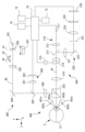
- FIG. It is a figure which shows the internal structure of an eye refraction measuring device.
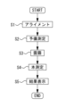
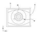
- 4 is a flow chart showing the control operation of the eye refraction measuring device; It is a figure which shows an example of an anterior-segment image.
- FIG. 10 is a diagram showing a display example of a measurement image;
- the eye refraction measurement device (for example, the eye refraction measurement device 1) of the present embodiment objectively measures the refraction characteristics of the subject's eye.
- the eye refraction measuring apparatus includes, for example, a measurement optical system (eg, measurement optical system 200) and an information acquisition section (eg, control section 70).
- the measurement optical system projects measurement light onto the fundus of the eye to be inspected, and receives reflected light from the fundus by a light receiving element (for example, the imaging element 226). Refractive properties are measured.
- the information acquisition unit acquires alignment information of the measurement optical system with respect to the eye to be inspected based on the pattern image.
- the eye refraction measuring apparatus of the present embodiment can acquire more appropriate alignment information and preferably measure eye refraction by having the configuration as described above.
- the pattern image may be, for example, a ring image, a Shack-Hartmann image (a plurality of point images or point group images), or any other pattern image whose refraction characteristics can be measured.
- the information acquisition unit may acquire the alignment information based on the light receiving position of the pattern image (the position on the image or the position on the light receiving element). For example, the deviation amount of the pattern image from the predetermined position may be acquired as the alignment information. Alignment information in the vertical and horizontal directions (XY directions) can be obtained.
- the information acquisition unit may acquire the positional deviation amount between the center position of the ring image and the optical axis as the alignment information. This makes it easy to evaluate the amount of misalignment even when the size or shape of the ring image differs due to individual differences in refractive power.
- the eye refraction measurement device may include a determination unit (eg, control unit 70).
- the judging unit judges whether the measured value of the refraction property is appropriate, for example, based on the alignment information. For example, the determination unit may determine that the measured value is inappropriate if the misalignment is large, and that the measured value is appropriate if the misalignment is small. As a result, for example, it is possible to suppress the use of a pattern image distorted by misalignment for measurement.
- the control unit (eg, control unit 70) of the eye refraction measurement device may execute the eye refraction measurement program stored in the storage unit (eg, storage unit 72).
- the eye refraction measurement program includes, for example, a measurement step and an information acquisition step.
- the measurement step for example, the measurement optical system projects measurement light onto the fundus of the eye to be inspected, and the light-receiving element receives the light reflected from the fundus of the eye to be measured. This is the step of measuring.
- the information acquisition step is, for example, a step of acquiring alignment information of the measurement optical system with respect to the subject's eye based on the pattern image.
- FIG. 1 is an external configuration diagram of an eye refraction measuring apparatus 1.
- the eye refraction measurement device 1 includes, for example, a base 2, a face support section 3, a drive section 4, a display section 75, an operation section 76, a measurement section 100, and the like.
- the face support part 3 is fixed to the base 2 and supports the subject's face.
- the drive unit 4 drives the measurement unit 100 with respect to the base 2 in the XYZ directions.
- the display unit 75 displays various kinds of information (for example, an observed image of the subject's eye, measurement results of the subject's eye, etc.).
- the operation unit 76 performs various settings.
- a display unit 75 with a touch panel also serves as the operation unit 76 .
- the measurement unit 100 accommodates an optical system, which will be described later.
- the horizontal direction of the eye refraction measuring apparatus 1 is represented as the X direction, the vertical direction as the Y direction, and the front and rear direction as the Z direction.
- FIG. 2 is a schematic configuration diagram of the optical system and control system of the eye refraction measuring device 1.
- the measurement unit 100 includes a measurement optical system 200, a fixation target optical system 300, an index projection optical system 400, an observation optical system 500, and the like.
- the measurement optical system 200 objectively measures the eye refractive power of the subject's eye E (for example, spherical power, cylindrical power, astigmatism axis angle, etc.).
- a fixation target optical system 300 presents a fixation target to the eye E to be examined.
- the index projection optical system 400 projects an alignment index for detecting the Z direction of the eye E to be examined.
- the observation optical system 500 images the anterior segment of the eye E to be examined.
- the measurement optical system 200 includes a light projecting optical system 210 and a light receiving optical system 220 .
- the projection optical system 210 projects a spot-shaped measurement light beam onto the fundus Ef of the eye E to be inspected through the center of the pupil of the eye E to be inspected.
- the light receiving optical system 220 takes out the reflected light flux of the measurement light flux reflected by the fundus oculi Ef in a ring shape via the pupil.
- the projection optical system 210 includes a light source 211, a relay lens 212, a hole mirror 213, a prism 214, a driving section 215, an objective lens 216, and the like.
- the light source 211 is arranged on the optical axis N1 of the measurement optical system 200 and has a positional relationship that is optically conjugate with the fundus oculi Ef.
- an LED Light Emitting Diode
- SLD Superluminescent Diode
- the opening of the hole mirror 213 has a positional relationship that is optically conjugate with the pupil.
- the prism 214 is arranged at a position away from the position conjugated to the pupil, and decenters the light flux passing through the prism 214 with respect to the optical axis N1.
- a plane-parallel plate may be obliquely arranged on the optical axis N1.
- the drive unit 215 rotates the prism 214 about the optical axis N1.
- the measurement light source 211 is used to project a spot-shaped measurement index onto the fundus oculi Ef via the pupil.
- the light source 211 desirably emits light in the infrared region that is less likely to cause glare to the subject. However, it is not necessarily limited to this. Further, in this embodiment, the light source 211 is also used as an illumination light source for photographing a retroillumination image of the eye E to be examined. That is, the inside of the pupil of the subject's eye E is illuminated by the fundus reflected light of the light flux (illumination light) emitted from the light source 211 .
- the light receiving optical system 220 includes an objective lens 216, a prism 214, a hall mirror 213, a relay lens 221, a total reflection mirror 222, a light receiving diaphragm 223, a collimator lens 224, a ring lens 225, an imaging device 226, and the like.
- Objective lens 216 , prism 214 , and hole mirror 213 are shared with projection optical system 210 .
- the relay lens 221 and the total reflection mirror 222 are arranged in the reflection direction of the hole mirror 213 .
- a light receiving diaphragm 223 , a collimator lens 224 , a ring lens 225 and an imaging element 226 are arranged in the reflection direction of the total reflection mirror 222 .
- the light receiving diaphragm 223 has a positional relationship that is optically conjugate with the fundus oculi Ef.
- the ring lens 225 has an optically conjugate positional relationship with the pupil.
- the ring lens 225 is composed of a lens portion in which a cylindrical lens is formed in a ring shape, and a light shielding portion in which a light shielding coating is applied to the portion other than the lens portion.
- the imaging device 226 has a positional relationship that is optically conjugate with the fundus oculi Ef.
- CCDs Charge-Coupled Devices
- CMOSs Complementary Metal-Oxide-Semiconductors
- an output signal from the imaging element 226 is input to the control section 70 .
- a beam splitter 230 is arranged between the subject's eye E and the objective lens 216 .
- the beam splitter 230 guides the measurement light flux from the fixation target optical system 300 to the eye E to be examined, and guides the reflected light flux from the anterior segment of the eye E to the observation optical system 500 .
- the measurement light flux emitted from the light source 211 passes through the relay lens 212, the hole mirror 213, the prism 214, the objective lens 216, and the beam splitter 230, and projects a spot-shaped measurement light flux onto the fundus oculi Ef.
- a point light source image is formed on the fundus oculi Ef.
- the prism 214 is rotated around the optical axis N1, and the pupil projected image (projected light flux on the pupil) of the opening of the hole mirror 213 is eccentrically rotated at high speed.
- a reflected light beam which is the measurement light beam reflected by the fundus oculi Ef, is reflected by the hole mirror 213 via the beam splitter 230 , the objective lens 216 and the prism 214 .
- the reflected light flux is further reflected by the total reflection mirror 222 via the relay lens 221 and condensed at the position of the light receiving diaphragm 223 .
- a ring-shaped image is formed on the imaging element 226 by the collimator lens 224 and the ring lens 225 .
- the measurement optical system 200 is not limited to the above configuration, and includes a light projecting optical system that projects the measurement light flux onto the fundus Ef of the eye to be examined E, and a light reception optical system that receives the reflected light flux of the measurement light flux reflected by the fundus Ef.
- Any measurement optical system may be used as long as it has
- the measurement optical system 200 may be a measurement optical system that projects a spot index onto the fundus oculi Ef and uses a Shack-Hartmann sensor to detect the reflected luminous flux of the spot index on the fundus oculi Ef.
- a fixation target optical system 300 projects a fixation target onto the eye E to be examined.
- the fixation target is used, for example, to guide fixation when measuring the eye E to be examined.
- the fixation target optical system 300 includes a light source 301, a fixation target plate 302, a projection lens 303, a total reflection mirror 304, a half mirror 305, an objective lens 306, a driving section 307, and the like.
- Light source 301 is arranged on optical axis N2.
- a fixation target is formed on the fixation target plate 302 , and the fixation target is presented to the subject's eye E by being illuminated by the light source 301 .
- the drive unit 307 can move the presentation position of the fixation target to be presented to the eye E by moving the positions of the light source 301 and the fixation target plate 302 in the direction of the optical axis N2. Further, the driving unit 307 can fog the eye E by moving the light source 301 and the fixation target plate 302 in the direction of the optical axis N2.
- an actuator for example, a stepping motor or the like
- a photointerrupter serving as a reference position may be used together.
- the drive unit 307 may change the presentation position of the fixation target by moving the position of the projection lens 303 with respect to the fixation target plate 302 .
- the subject's eye E may be fogged by moving the position of the projection lens 303 .
- a light beam from light source 301 passes through fixation target plate 302 and projection lens 303 along optical axis N2, is reflected by total reflection mirror 304, passes through half mirror 305 and objective lens 306, and reaches beam splitter 230. and projected onto the subject's eye along the optical axis N1.
- the index projection optical system 400 includes a first index projection optical system and a second index projection optical system.
- the first index projection optical system projects an infinite alignment index onto the cornea of the eye E to be examined.
- the second index projection optical system projects a finite alignment index onto the cornea of the eye E to be examined.
- the first target projection optical system has point light sources 401a and 401b, collimator lenses 402a and 402b, and the like.
- FIG. 2 shows only part of the first target projection optical system.
- the point light sources 401a and 401b may be light sources that emit near-infrared light.
- the collimator lenses 402a and 402b collimate the luminous flux emitted from the point light source into a parallel luminous flux (substantially parallel luminous flux).
- a plurality of these point light sources and collimator lenses are arranged concentrically around the optical axis N1 at intervals of 45 degrees, and are symmetrical with respect to a vertical plane passing through the optical axis N1. As a result, an infinite alignment index is projected onto the cornea of the eye E to be examined.
- the second target projection optical system has point light sources 403a and 403b.
- FIG. 2 shows only part of the second target projection optical system.
- the point light sources 403a and 403b may be light sources that emit near-infrared light.
- these point light sources are arranged at positions different from the point light sources of the first target projection optical system. As a result, a finite distance alignment index is projected onto the eye E to be examined.
- the configuration using a point-like light source as the light source of the first target projection optical system and the second target projection optical system has been described as an example, but the present invention is not limited to this.
- a ring-shaped light source or a line-shaped light source may be used as the light source.
- the second target projection optical system can also be used as an anterior ocular segment illumination for illuminating the anterior segment of the eye E to be inspected, an index for measuring the shape of the cornea of the eye E to be inspected, and the like.
- the observation optical system 500 includes an objective lens 306, a half mirror 305, an imaging lens 501, an imaging element 502, and the like.
- the objective lens 306 and half mirror 305 are shared with the fixation target optical system 300 .
- the imaging lens 501 and the imaging device 502 are arranged in the reflection direction of the half mirror 305 .
- the imaging element 502 has a positional relationship that is optically conjugate with the anterior segment of the eye E to be examined.
- the imaging element 502 captures a front image of the anterior segment of the eye E to be examined.
- a transillumination image which is a type of anterior segment image, is also captured by the image sensor 502 .
- the output from the imaging element 502 is input to the control section 70 and the display section 75 .
- the observation optical system 500 also serves as an optical system for detecting the alignment index image formed on the cornea of the eye to be examined E by the index projection optical system 400, and the controller 70 detects the position of the alignment index image.
- the control unit 70 includes a CPU (processor) 71, a storage unit (nonvolatile memory, etc.) 72, and the like.
- the CPU 71 controls the eye refraction measurement device 1 .
- the storage unit 72 is a non-transitory storage medium that can retain stored content even when power supply is interrupted.
- a hard disk drive, a flash ROM, a removable USB memory, or the like may be used as the storage unit 72 .
- various programs executed by the CPU 71 such as an eye refraction measurement program for executing eye refraction measurement processing (see FIG. 3), which will be described later, are stored in the storage unit 72 .
- the control unit 70 is electrically connected to the drive unit 4, the display unit 75 (the operation unit 76), and the like.
- each light source, each imaging element, each drive section, and the like provided in the measurement section 100 are electrically connected to the control section 70 .
- the eye refraction measuring apparatus 1 of this embodiment evaluates the alignment state of the measuring unit 100 with respect to the subject's eye E based on the amount of positional deviation between the central position of the ring image and the optical axis N1 of the apparatus.
- Step S1 Alignment
- the control unit 70 aligns the apparatus with respect to the subject's eye.
- the control unit 70 turns on a point light source included in the target projection optical system 400 .
- an alignment index image is projected onto the cornea of the eye E to be examined.
- the examiner fixes the subject's face on the face support portion 3 and instructs the subject to observe the fixation target projected by the fixation target optical system 300 .
- Alignment index images at infinity and finite distances are projected onto the anterior segment of the eye E to be examined.
- the anterior segment of the subject's eye E is detected by the imaging device 502 included in the observation optical system 500, and the anterior segment image is displayed on the display unit 75 (see FIG. 4).
- the control unit 70 detects the amount of misalignment of the measurement unit 100 with respect to the subject's eye E based on the positional relationship between the infinite alignment index M1 and the finite alignment index M2 detected from the anterior segment image Q1.
- the control unit 70 controls the driving unit 4 based on the detected deviation amount, and three-dimensionally drives the measuring unit 100 to align the eye E to be examined.
- alignment may be performed manually by the examiner operating the operation unit 76 .
- Step S2 Preliminary measurement
- the controller 70 starts preliminary measurement.
- the control unit 70 arranges the fixation target plate 302 at an initial position d1 (see FIG. 2) optically sufficiently distant from the eye E to present the fixation target.
- the fixation target is observed blurry.
- the control unit 70 causes the light source 211 to irradiate the measurement light flux, and causes the imaging element 226 to image the reflected light flux of the measurement light flux as a ring image.
- a measurement image captured by the imaging device 226 is stored in the storage unit 72 .
- the control unit 70 calculates the eye refractive power in preliminary measurement based on the measurement image stored in the storage unit 72 .
- the subject's eye E is an emmetropic eye (that is, the spherical power is 0D)
- the reflected luminous flux from the fundus oculi Ef enters the ring lens 225 as a parallel luminous flux (substantially parallel luminous flux). Therefore, a ring image having the same size as that of the ring lens 225 is formed on the imaging device 226 .
- the subject's eye E is a hyperopic eye (for example, the spherical power is +3D, etc.)
- a ring image magnified according to the spherical power is formed on the imaging device 226 .
- the subject's eye E is a myopic eye (for example, the spherical power is -3D, etc.)
- a ring image reduced according to the spherical power is formed on the imaging device 226 .
- the image pickup device 226 has an elliptical shape according to the cylinder power, and the cylinder axis angle is 45 degrees. A ring image that is tilted according to the angle is formed.
- the control unit 70 thins the image data of the ring image and identifies the position of the ring image in each meridian direction.
- the position of the ring image may be specified by detecting the luminance signal and obtaining its peak value, barycentric position, and the like.
- the control unit 70 approximates the ring image by the method of least squares or the like, and obtains the eye refractive power in each meridional direction from the shape of the approximated ring image. Further, the control unit 70 obtains the objectively measured eye refractive power of the subject's eye E by performing a predetermined process on the eye refractive power.
- Step S3 clouds
- the control unit 70 performs the clouding operation.
- the preliminary measurement of the eye refractive power of the subject's eye E may have been measured in a state in which the subject's eye E was accommodated. That is, there is a possibility that the preliminary measurement of the ocular refractive power of the eye to be examined E was measured while the thickness of the crystalline lens of the eye E to be examined (that is, the refractive power of the crystalline lens) was changed. Therefore, the control unit 70 fogs the eye E to be examined and cancels the adjustment of the eye E to be examined.
- the control unit 70 moves the fixation target plate 302 to the cloudy start position d2 where the subject's eye E is focused based on the eye refractive power of the subject's eye E obtained by preliminary measurement. As a result, the eye E to be examined can clearly observe the fixation target.
- the control unit 70 moves the fixation target plate 302 to a cloudiness completion position d3 corresponding to a predetermined amount of cloudiness ⁇ d.
- the fixation target plate 302 is moved in the direction of optically moving away from the subject's eye E from the fogging start position d2 toward the fogging end position d3.
- the fixation target plate 302 reaches the clouding completion position d3, the clouding of the subject's eye E is completed.
- the subject's eye E is fogged, and the subject's eye E is no longer focused on the fixation target plate 302 .
- the eye refractive power of the subject's eye E approaches the true value from the eye refractive power obtained in the preliminary measurement, and the adjustment of the subject's eye E is released.
- Step S4 Measurement
- the control unit 70 starts the main measurement in a state where the subject's eye E is fogged. For example, the control unit 70 captures and analyzes a ring image at each predetermined timing, and continuously measures the eye refractive power of the eye E to be examined.
- FIG. 5 is an example of the measurement image Q2 captured by the imaging device 226.
- the control unit 70 calculates the center position P of the ring image R from the measurement image Q2. For example, the control unit 70 obtains an ellipse that approximates the ring image by the above-described method of least squares or the like, and calculates the positional deviation amount D in the XY direction between the center coordinates of the ellipse and the optical axis N1 as the alignment information.
- the position of the optical axis N1 in the image pickup device 226 may be determined by design or experiment, or may be the position of the central pixel of the image pickup device 226 .
- the control unit 70 evaluates the alignment state using this deviation amount D, and determines whether the measured value is appropriate.
- control unit 70 determines that the alignment state is poor when the deviation amount D is equal to or greater than a predetermined distance (or the number of pixels, etc.), and rejects the measurement value obtained from the ring image R at this time. . Further, the control unit 70 determines that the alignment state is good when the deviation amount D is less than the predetermined distance, and adopts the measurement value obtained from the ring image R at this time.
- the reliability of the measurement result may be used.
- the reliability is obtained, for example, by determining the amount of deviation between the elliptical shape of the measured image stored in the storage unit 72 when elliptical approximation is performed and the ring shape of the measured image for each meridian direction, and is based on the sum of the amounts of deviation. may be used to calculate the reliability.
- the control unit 70 may calculate an intermediate value or the like and use it as the representative value of the eye refractive power. If there is no data that satisfies the above conditions, the representative value may be determined based on the distance between the center position P of the ring image R and the optical axis N1. For example, data in which the center position P and the optical axis N1 are close (for example, the closest data) may be used as the representative value.
- the control unit 70 stores the eye refractive power in the main measurement in the storage unit 72 .
- Step S5 Result display
- the control unit 70 displays the measurement result of the eye refractive power on the display unit 75 .
- the control unit 70 causes the display unit 75 to display the measurement results of the eye refractive power such as the spherical power, the cylindrical power, and the axis of astigmatism.
- the alignment information can be obtained separately from the anterior segment image. For example, when the anterior segment image is not captured during measurement, or when the timing of capturing the anterior segment image used for determining the alignment state is different from the timing of capturing the ring image, more appropriate alignment information can be obtained. can be obtained, and the refractive characteristics of the eye to be examined can be preferably measured.
- the permissible range of the alignment state by the anterior segment image is widened so that the measurement can be started smoothly
- the permissible range of the alignment state by the ring image is changed to that of the alignment state by the anterior segment image.
- the eye refraction measurement device 1 measures eye refractive power in the above embodiment, it can also be applied to devices that measure other refractive characteristics.
- the deviation between the center position of the pattern image and the optical axis may be detected.
- wavefront aberration is obtained using a Shack-Hartmann sensor or the like
- the amount of deviation between the position of the central point image and the optical axis may be detected. In this way, even in the measurement of other refraction characteristics, it is possible to properly detect the alignment information at the time of measurement.
- control unit 70 may control the driving unit 4 based on the alignment information acquired based on the pattern image to align (or track) the measuring unit 100 .
- control unit 72 storage unit 75 display unit 76 operation unit 100 measurement unit 200 measurement optical system 300 fixation target optical system 400 target projection optical system 500 observation optical system
Landscapes
- Life Sciences & Earth Sciences (AREA)
- Health & Medical Sciences (AREA)
- Medical Informatics (AREA)
- Biophysics (AREA)
- Ophthalmology & Optometry (AREA)
- Engineering & Computer Science (AREA)
- Biomedical Technology (AREA)
- Heart & Thoracic Surgery (AREA)
- Physics & Mathematics (AREA)
- Molecular Biology (AREA)
- Surgery (AREA)
- Animal Behavior & Ethology (AREA)
- General Health & Medical Sciences (AREA)
- Public Health (AREA)
- Veterinary Medicine (AREA)
- Eye Examination Apparatus (AREA)
Abstract
Description
(2) 被検眼の屈折特性を他覚的に測定する眼屈折測定装置において実行される眼屈折測定プログラムであって、前記眼屈折測定装置の制御手段によって実行されることで、測定光学系によって、前記被検眼の眼底に測定光を投光し、前記眼底からの反射光を受光素子で受光して得られたパターン像に基づいて、前記被検眼の屈折特性を測定する測定ステップと、前記パターン像に基づいて、前記被検眼に対する前記測定光学系のアライメント情報を取得する情報取得ステップと、を前記眼屈折測定装置に実行させることを特徴とする。
本開示の実施形態について説明する。本実施形態の眼屈折測定装置(例えば、眼屈折測定装置1)は、被検眼の屈折特性を他覚的に測定する。眼屈折測定装置は、例えば、測定光学系(例えば、測定光学系200)と、情報取得部(例えば、制御部70)を備える。測定光学系は、例えば、被検眼の眼底に測定光を投光し、眼底からの反射光を受光素子(例えば、撮像素子226)で受光して得られたパターン像に基づいて、被検眼の屈折特性を測定する。情報取得部は、パターン像に基づいて、被検眼に対する測定光学系のアライメント情報を取得する。本実施形態の眼屈折測定装置は、上記のような構成を備えることによって、より適正なアライメント情報を取得して、好適に眼屈折測定を測定できる。
以下、本開示に係る実施例について説明する。図1は眼屈折測定装置1の外観構成図である。眼屈折測定装置1は、例えば、基台2、顔支持部3、駆動部4、表示部75、操作部76、および測定部100等を備える。顔支持部3は、基台2に固定され、被検者の顔を支持する。駆動部4は、測定部100を基台2に対してXYZ方向に駆動させる。表示部75は、各種の情報(例えば、被検眼の観察像、被検眼の測定結果、等)を表示する。操作部76は、各種の設定を行う。本実施例では、タッチパネル付きの表示部75が操作部76を兼用する。測定部100は、後述する光学系を収納する。なお、本実施例では、図2のように眼屈折測定装置1の左右方向をX方向、上下方向をY方向、前後方向をZ方向として表す。
例えば、測定光学系200は、投光光学系210と、受光光学系220と、を備える。投光光学系210は、被検眼Eにおける瞳孔の中心部を介して、被検眼Eの眼底Efにスポット状の測定光束を投影する。受光光学系220は、眼底Efにより反射された測定光束の反射光束を、瞳孔を介してリング状に取り出す。
固視標光学系300は、被検眼Eに固視標を投影する。固視標は、例えば、被検眼Eを測定する際に固視を誘導するために用いられる。例えば、固視標光学系300は、光源301、固視標板302、投光レンズ303、全反射ミラー304、ハーフミラー305、対物レンズ306、駆動部307、等を備える。光源301は光軸N2上に配置される。固視標板302には、固視標が形成され、光源301によって照明されることで被検眼Eに固視標を呈示する。駆動部307は、光源301及び固視標板302の位置を光軸N2方向へ移動させることによって、被検眼Eに呈示する固視標の呈示位置を移動させることができる。また、駆動部307は、光源301及び固視標板302を光軸N2方向へ移動させることで、被検眼Eに雲霧を掛けることができる。例えば、駆動部307としては、アクチュエータ(例えば、ステッピングモータ等)と、基準位置となるフォトインタラプタと、が併用されてもよい。なお、駆動部307は、固視標板302に対して投光レンズ303の位置を移動させることによって固視標の呈示位置を変更してもよい。したがって、投光レンズ303の位置を移動させることによって被検眼Eに雲霧を掛けてもよい。光源301からの光束は、光軸N2に沿って固視標板302および投光レンズ303を通過し、全反射ミラー304で反射され、ハーフミラー305、対物レンズ306を通過した後、ビームスプリッタ230によって反射され、光軸N1に沿って被検眼に投影される。
指標投影光学系400は、第1指標投影光学系と、第2指標投影光学系と、を備える。第1指標投影光学系は、被検眼Eの角膜に無限遠のアライメント指標を投影する。第2指標投影光学系は、被検眼Eの角膜に有限遠のアライメント指標を投影する。
例えば、観察光学系500は、対物レンズ306、ハーフミラー305、撮像レンズ501、撮像素子502、等を備える。対物レンズ306及びハーフミラー305は、固視標光学系300と共用される。撮像レンズ501及び撮像素子502は、ハーフミラー305の反射方向に配置される。撮像素子502は、被検眼Eの前眼部と光学的に共役な位置関係となっている。この撮像素子502によって、被検眼Eの前眼部の正面画像が撮像される。前眼部画像の一種である徹照像も、撮像素子502によって撮像される。例えば、撮像素子502からの出力は、制御部70及び表示部75に入力される。なお、観察光学系500は、指標投影光学系400によって被検眼Eの角膜に形成されたアライメント指標像を検出する光学系を兼ね、制御部70によってアライメント指標像の位置を検出する。
例えば、制御部70は、CPU(プロセッサ)71、記憶部(不揮発性メモリなど)72等を備える。CPU71は、眼屈折測定装置1の制御を司る。記憶部72は、電源の供給が遮断されても記憶内容を保持できる非一過性の記憶媒体である。例えば、ハードディスクドライブ、フラッシュROM、および着脱可能なUSBメモリ等を記憶部72として使用してもよい。本実施例では、後述する眼屈折測定処理(図3参照)を実行するための眼屈折測定プログラム等のCPU71が実行する各種プログラムが、記憶部72に記憶される。
続いて、本実施例の眼屈折測定装置1を用いて被検眼の眼屈折力を測定するときの制御動作を図3のフローチャートに基づいて説明する。本実施例の眼屈折測定装置1は、リング像の中心位置と装置の光軸N1との位置ずれ量に基づいて、被検眼Eに対する測定部100のアライメント状態を評価する。
まず、制御部70は、被検眼に対する装置のアライメントを行う。例えば、制御部70は、指標投影光学系400が備える点光源を点灯させる。これによって、被検眼Eの角膜にアライメント指標像が投影される。検者は、顔支持部3に被検者の顔を固定させて、固視標光学系300によって投影された固視標を観察するよう被検者に指示する。被検眼Eの前眼部には、無限遠と有限遠のアライメント指標像が投影される。被検眼Eの前眼部は、観察光学系500が備える撮像素子502により検出され、前眼部画像が表示部75に表示される(図4参照)。制御部70は、前眼部画像Q1から検出された無限遠のアライメント指標M1と有限遠のアライメント指標M2の位置関係に基づいて、被検眼Eに対する測定部100のアライメントのずれ量を検出する。制御部70は、検出したずれ量に基づいて駆動部4を制御し、測定部100を3次元的に駆動させて被検眼Eに対するアライメントを行う。もちろん、検者が操作部76を操作することによって、手動でアライメントを行ってもよい。
アライメントが完了すると、制御部70は、予備測定を開始する。制御部70は、予備測定において、被検眼Eに対して光学的に十分な遠方の初期位置d1(図2参照)に固視標板302を配置して固視標を呈示する。例えば、被検眼Eが近視眼であると、被検眼Eの焦点は固視標に合わず、固視標がぼやけて観察される。制御部70は、光源211から測定光束を照射させ、測定光束の反射光束をリング像として撮像素子226に撮像させる。撮像素子226によって撮影された測定画像は、記憶部72に記憶される。
続いて、制御部70は、雲霧動作を行う。被検眼Eの予備測定の眼屈折力は、被検眼Eに調節が働いた状態で測定された可能性がある。すなわち、被検眼Eの予備測定の眼屈折力は、被検眼Eが水晶体の厚み(つまり、水晶体の屈折力)を変化させた状態で測定された可能性がある。このため、制御部70は、被検眼Eに対して雲霧を掛け、被検眼Eの調節を解除させる。
制御部70は、被検眼Eに雲霧を行った状態で、本測定を開始する。例えば、制御部70は、所定のタイミング毎にリング像を撮像して解析し、被検眼Eの眼屈折力を連続的に測定する。
制御部70は、眼屈折力の測定結果を表示部75に表示する。例えば、制御部70は、球面度数、円柱度数、乱視軸などの眼屈折力の測定結果を表示部75に表示させる。
72 記憶部
75 表示部
76 操作部
100 測定部
200 測定光学系
300 固視標光学系
400 指標投影光学系
500 観察光学系
Claims (5)
- 被検眼の屈折特性を他覚的に測定する眼屈折測定装置であって、
前記被検眼の眼底に測定光を投光し、前記眼底からの反射光を受光素子で受光して得られたパターン像に基づいて、前記被検眼の屈折特性を測定する測定光学系と、
前記パターン像に基づいて、前記被検眼に対する前記測定光学系のアライメント情報を取得する情報取得手段と、
を備えることを特徴とする眼屈折測定装置。 - 前記情報取得手段は、前記パターン像の受光位置に基づいて前記アライメント情報を取得することを特徴とする請求項1の眼屈折測定装置。
- 前記パターン像はリング像であり、
前記情報取得手段は、前記リング像の中心位置と、前記測定光学系の光軸との位置ずれ量を前記アライメント情報として取得することを特徴とする請求項2の眼屈折測定装置。 - 前記アライメント情報に基づいて、前記屈折特性の測定値の適否を判定する判定手段を備えることを特徴とする請求項1~3のいずれかの眼屈折測定装置。
- 被検眼の屈折特性を他覚的に測定する眼屈折測定装置において実行される眼屈折測定プログラムであって、前記眼屈折測定装置の制御手段によって実行されることで、
測定光学系によって、前記被検眼の眼底に測定光を投光し、前記眼底からの反射光を受光素子で受光して得られたパターン像に基づいて、前記被検眼の屈折特性を測定する測定ステップと、
前記パターン像に基づいて、前記被検眼に対する前記測定光学系のアライメント情報を取得する情報取得ステップと、
を前記眼屈折測定装置に実行させることを特徴とする眼屈折測定プログラム。
Priority Applications (2)
| Application Number | Priority Date | Filing Date | Title |
|---|---|---|---|
| JP2023556404A JPWO2023074579A1 (ja) | 2021-10-27 | 2022-10-21 | |
| KR1020247016638A KR20240090569A (ko) | 2021-10-27 | 2022-10-21 | 안굴절 측정 장치 및 안굴절 측정 프로그램 |
Applications Claiming Priority (2)
| Application Number | Priority Date | Filing Date | Title |
|---|---|---|---|
| JP2021175692 | 2021-10-27 | ||
| JP2021-175692 | 2021-10-27 |
Publications (1)
| Publication Number | Publication Date |
|---|---|
| WO2023074579A1 true WO2023074579A1 (ja) | 2023-05-04 |
Family
ID=86159877
Family Applications (1)
| Application Number | Title | Priority Date | Filing Date |
|---|---|---|---|
| PCT/JP2022/039336 Ceased WO2023074579A1 (ja) | 2021-10-27 | 2022-10-21 | 眼屈折測定装置、および眼屈折測定プログラム |
Country Status (3)
| Country | Link |
|---|---|
| JP (1) | JPWO2023074579A1 (ja) |
| KR (1) | KR20240090569A (ja) |
| WO (1) | WO2023074579A1 (ja) |
Cited By (1)
| Publication number | Priority date | Publication date | Assignee | Title |
|---|---|---|---|---|
| CN118490158A (zh) * | 2024-07-11 | 2024-08-16 | 深圳盛达同泽科技有限公司 | 屈光信息测量方法、装置、设备、存储介质及产品 |
Citations (5)
| Publication number | Priority date | Publication date | Assignee | Title |
|---|---|---|---|---|
| JPH10118025A (ja) * | 1996-10-16 | 1998-05-12 | Topcon Corp | 眼科装置 |
| JP2003532476A (ja) * | 2000-05-08 | 2003-11-05 | アルコン,インコーポレイティド | 波面分析を用いた、光学系の客観的な測定および矯正のための装置および方法 |
| JP2005312501A (ja) * | 2004-04-27 | 2005-11-10 | Canon Inc | 眼屈折力測定装置 |
| JP2013022122A (ja) * | 2011-07-19 | 2013-02-04 | Topcon Corp | 眼特性の測定方法及び眼科装置 |
| JP2016500282A (ja) * | 2012-12-10 | 2016-01-12 | トレイシー テクノロジーズ,コープ | 目の視軸を他覚的に決定し、且つその屈折を測定するための方法 |
Family Cites Families (1)
| Publication number | Priority date | Publication date | Assignee | Title |
|---|---|---|---|---|
| JPH08280627A (ja) | 1995-04-19 | 1996-10-29 | Nidek Co Ltd | 眼科装置 |
-
2022
- 2022-10-21 JP JP2023556404A patent/JPWO2023074579A1/ja active Pending
- 2022-10-21 WO PCT/JP2022/039336 patent/WO2023074579A1/ja not_active Ceased
- 2022-10-21 KR KR1020247016638A patent/KR20240090569A/ko active Pending
Patent Citations (5)
| Publication number | Priority date | Publication date | Assignee | Title |
|---|---|---|---|---|
| JPH10118025A (ja) * | 1996-10-16 | 1998-05-12 | Topcon Corp | 眼科装置 |
| JP2003532476A (ja) * | 2000-05-08 | 2003-11-05 | アルコン,インコーポレイティド | 波面分析を用いた、光学系の客観的な測定および矯正のための装置および方法 |
| JP2005312501A (ja) * | 2004-04-27 | 2005-11-10 | Canon Inc | 眼屈折力測定装置 |
| JP2013022122A (ja) * | 2011-07-19 | 2013-02-04 | Topcon Corp | 眼特性の測定方法及び眼科装置 |
| JP2016500282A (ja) * | 2012-12-10 | 2016-01-12 | トレイシー テクノロジーズ,コープ | 目の視軸を他覚的に決定し、且つその屈折を測定するための方法 |
Cited By (1)
| Publication number | Priority date | Publication date | Assignee | Title |
|---|---|---|---|---|
| CN118490158A (zh) * | 2024-07-11 | 2024-08-16 | 深圳盛达同泽科技有限公司 | 屈光信息测量方法、装置、设备、存储介质及产品 |
Also Published As
| Publication number | Publication date |
|---|---|
| KR20240090569A (ko) | 2024-06-21 |
| JPWO2023074579A1 (ja) | 2023-05-04 |
Similar Documents
| Publication | Publication Date | Title |
|---|---|---|
| JP4769923B2 (ja) | 眼内レンズの計算に好適な、眼の軸方向長さ及び/又は角膜の曲率及び/又は前房深さを非接触的に測定するための一体化装置 | |
| JP4492847B2 (ja) | 眼屈折力測定装置 | |
| EP2415393B1 (en) | Ophthalmic apparatus | |
| US20190150735A1 (en) | Ophthalmic apparatus | |
| US8485663B2 (en) | Ophthalmic apparatus | |
| US11471049B2 (en) | Ophthalmologic apparatus | |
| US12133687B2 (en) | Ophthalmic apparatus | |
| JP7459491B2 (ja) | 眼科測定装置 | |
| JP6589378B2 (ja) | 眼科測定装置 | |
| JP6736356B2 (ja) | 眼科装置 | |
| WO2023074579A1 (ja) | 眼屈折測定装置、および眼屈折測定プログラム | |
| WO2023054612A1 (ja) | 眼科装置 | |
| JP6003234B2 (ja) | 眼底撮影装置 | |
| JP7035630B2 (ja) | 眼科装置 | |
| JP6586599B2 (ja) | 眼屈折力測定装置 | |
| JP2023171595A (ja) | 眼科装置 | |
| JP2016106962A (ja) | 眼科装置及びその制御方法 | |
| JP3927873B2 (ja) | 眼屈折力測定装置 | |
| JP4159190B2 (ja) | 眼科測定装置 | |
| JP7216562B2 (ja) | 眼科装置 | |
| JP7589625B2 (ja) | 眼科装置 | |
| JP7714897B2 (ja) | 眼科装置及び眼科プログラム | |
| JP6823339B2 (ja) | 眼科装置 | |
| JP2022119038A (ja) | 眼屈折測定装置、および眼屈折測定プログラム | |
| JP7714896B2 (ja) | 眼科装置 |
Legal Events
| Date | Code | Title | Description |
|---|---|---|---|
| 121 | Ep: the epo has been informed by wipo that ep was designated in this application |
Ref document number: 22886906 Country of ref document: EP Kind code of ref document: A1 |
|
| WWE | Wipo information: entry into national phase |
Ref document number: 2023556404 Country of ref document: JP |
|
| ENP | Entry into the national phase |
Ref document number: 20247016638 Country of ref document: KR Kind code of ref document: A |
|
| NENP | Non-entry into the national phase |
Ref country code: DE |
|
| 122 | Ep: pct application non-entry in european phase |
Ref document number: 22886906 Country of ref document: EP Kind code of ref document: A1 |