WO2023074567A1 - ワイヤーロープ - Google Patents
ワイヤーロープ Download PDFInfo
- Publication number
- WO2023074567A1 WO2023074567A1 PCT/JP2022/039290 JP2022039290W WO2023074567A1 WO 2023074567 A1 WO2023074567 A1 WO 2023074567A1 JP 2022039290 W JP2022039290 W JP 2022039290W WO 2023074567 A1 WO2023074567 A1 WO 2023074567A1
- Authority
- WO
- WIPO (PCT)
- Prior art keywords
- wire
- vickers hardness
- core
- wires
- wire rope
- Prior art date
- Legal status (The legal status is an assumption and is not a legal conclusion. Google has not performed a legal analysis and makes no representation as to the accuracy of the status listed.)
- Ceased
Links
Images



Classifications
-
- D—TEXTILES; PAPER
- D07—ROPES; CABLES OTHER THAN ELECTRIC
- D07B—ROPES OR CABLES IN GENERAL
- D07B1/00—Constructional features of ropes or cables
- D07B1/06—Ropes or cables built-up from metal wires, e.g. of section wires around a hemp core
- D07B1/0673—Ropes or cables built-up from metal wires, e.g. of section wires around a hemp core having a rope configuration
- D07B1/068—Ropes or cables built-up from metal wires, e.g. of section wires around a hemp core having a rope configuration characterised by the strand design
-
- D—TEXTILES; PAPER
- D07—ROPES; CABLES OTHER THAN ELECTRIC
- D07B—ROPES OR CABLES IN GENERAL
- D07B5/00—Making ropes or cables from special materials or of particular form
- D07B5/007—Making ropes or cables from special materials or of particular form comprising postformed and thereby radially plastically deformed elements
-
- D—TEXTILES; PAPER
- D07—ROPES; CABLES OTHER THAN ELECTRIC
- D07B—ROPES OR CABLES IN GENERAL
- D07B2201/00—Ropes or cables
- D07B2201/20—Rope or cable components
- D07B2201/2001—Wires or filaments
- D07B2201/2002—Wires or filaments characterised by their cross-sectional shape
-
- D—TEXTILES; PAPER
- D07—ROPES; CABLES OTHER THAN ELECTRIC
- D07B—ROPES OR CABLES IN GENERAL
- D07B2201/00—Ropes or cables
- D07B2201/20—Rope or cable components
- D07B2201/2001—Wires or filaments
- D07B2201/2006—Wires or filaments characterised by a value or range of the dimension given
-
- D—TEXTILES; PAPER
- D07—ROPES; CABLES OTHER THAN ELECTRIC
- D07B—ROPES OR CABLES IN GENERAL
- D07B2201/00—Ropes or cables
- D07B2201/20—Rope or cable components
- D07B2201/2015—Strands
- D07B2201/2023—Strands with core
Definitions
- This disclosure relates to wire ropes.
- Patent Document 1 discloses an elastic wire obtained by compressing and deforming a stranded wire formed by twisting a plurality of wire strands having a circular cross-section into a non-circular cross-sectional shape by swaging.
- the elastic wire of Patent Document 1 is formed by swaging, the lateral wire has a substantially uniform cross-sectional hardness distribution, and the outer surface of the lateral wire has uneven surface roughness. Therefore, the elastic wire of Patent Document 1 does not have good bending durability.
- An object of the present disclosure is to provide a wire rope capable of improving bending durability.
- a wire rope according to one aspect of the present disclosure is a wire rope including a strand formed by winding a plurality of metal wires, wherein the strand comprises the plurality of metal wires and a plurality of other metal wires, each of which is a side wire arranged on the outer periphery of the core wire, and the side wire has a cross section of the circle of the core wire It has ends located at both ends in the circumferential direction, and the Vickers hardness of the portion of the end that contacts the end of the adjacent lateral wire is 1 higher than the Vickers hardness of the portion that does not contact the other adjacent lateral wire. % or more, and the surface roughness Ra of the outer peripheral surface of the side wire is 0.10 ⁇ m or less.
- the Vickers hardness of the portion in contact with the end of the adjacent lateral wire may be higher by 3% or more than the Vickers hardness of the portion not in contact with the other adjacent lateral wire.
- a wire rope according to one aspect of the present disclosure may be formed by winding a plurality of the strands described above.
- the present disclosure can provide a wire rope that can improve bending durability.
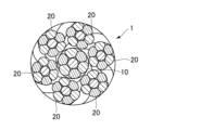
- FIG. 1 is an external view of a wire rope according to an embodiment
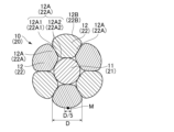
- FIG. It is a cross-sectional view of a wire rope. It is a cross-sectional view of a core strand (side strand).
- FIG. 4A is a cross-sectional view of the core strand (side strand) in the manufacturing process;
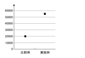
- FIG. 4 is an explanatory diagram of Vickers hardness measurement positions of lateral wires of a wire rope. It is a figure which shows the result of bending-durability evaluation.
- FIG. 1 is an external view of a wire rope 1 according to one embodiment of the present disclosure.
- FIG. 2 is a cross-sectional view of the wire rope 1.
- FIG. 3 is a cross-sectional view of the core strand 10 (side strands 20).
- the wire rope 1 has a core strand 10 and a plurality of (eg, six) side strands 20, which are twisted together.
- the core strand 10 and each side strand 20 are composed of twisted wires in which a plurality of (for example, seven) strands are twisted together.
- the core strand 10 includes a core wire 11 arranged at the center of the core strand 10 among the plurality of wires, and a plurality of other wires (six wires). and a side wire 12 arranged on the outer circumference of the core wire 11 so as to be in contact with each other.
- the core wire 11 is a metal element wire with a circular cross section that extends from the tip to the base end at the center of the core strand 10 .
- the material of the core wire 11 is not particularly limited, for example, stainless steel or the like is used.
- the core wire 11 is configured such that the Vickers hardness of the outer peripheral portion in the cross section is higher than the Vickers hardness of the central portion in the cross section. As a result, the flexibility of the core wire 11 is maintained, the abrasion resistance due to contact with the lateral wire 12 is improved, and the bending resistance durability is improved.
- the plurality of side wires 12 are metal wires that are helically wound around the core wire 11 in the longitudinal direction while being in contact with the core wire 11 .
- the material of the core wire 12 is not particularly limited, for example, stainless steel or the like is used.
- the cross-sectional shape of the side wire 12 is non-circular and substantially trapezoidal.
- the side wire 12 has end portions 12A located at both ends of the core wire 11 in the circumferential direction in its cross section. Each end 12A is in surface contact with the end 12A of another side wire 12 adjacent thereto.
- Each side wire 12 has an outer peripheral surface 12B exposed to the outside.
- the Vickers hardness of the contact portion 12A1 that contacts the end portion 12A of the other adjacent side wire 12 is configured to be higher than the Vickers hardness of the non-contact portion 12A2 that does not contact the other adjacent side wire 12.
- the Vickers hardness of the contact portion 12A1 is higher by 1% or more than the Vickers hardness of the non-contact portion 12A2.
- the outer peripheral surface 12B of the side wire 12 has a surface roughness Ra of 0.10 ⁇ m or less.
- Each side strand 20 also has a core wire 21 and a side wire 22 like the core strand 10 and has a configuration similar to that of the core strand 10 . That is, the side wire 22 has end portions 22A located at both ends of the core wire 21 in the circumferential direction in its cross section. Each end portion 22A is in surface contact with the end portion 22A of another side wire 22 adjacent thereto.
- the Vickers hardness of the contact portion 22A1 is higher than that of the non-contact portion 22A2.
- the Vickers hardness of the contact portion 22A1 is 1% or more higher than the Vickers hardness of the non-contact portion 22A2, and the surface roughness Ra of the outer peripheral surface 22B of the side wire 22 is 0.10 ⁇ m or less.
- the Vickers hardness of the portions of the strands 10, 20 in contact with each other is 1% or more higher than the Vickers hardness of other portions, and the surfaces of the outer peripheral surfaces 12B, 22B of the lateral wires 12, 22 Roughness Ra is configured to be 0.10 ⁇ m or less.
- the abrasion resistance and bending resistance durability of each strand 10, 20 can be improved.
- the wear resistance and bending durability of the wire rope 1 can be improved.
- the Vickers hardness of the contact portions 12A1 and 22A1 is preferably higher than the Vickers hardness of the non-contact portions 12A2 and 22A2 by 3% or more, more preferably by 5% or more. Thereby, the wear resistance and bending resistance of each strand 10, 20 can be further improved.
- the surface roughness Ra of the outer peripheral surfaces 12B, 22B of the side wires 12, 22 is preferably 0.04 ⁇ m or less.
- FIG. 4 is a cross-sectional view of the core stranded wire 14 (side stranded wire 24) in the manufacturing process.
- a core strand 10 and a plurality of side strands 20 are produced.
- a core wire 11 and a plurality of side wires 13 having a circular cross section are prepared and twisted together.
- a stranded core wire 14 is formed in which all strands have a circular cross section.
- the core strand 10 having the lateral wire 12 having a substantially trapezoidal cross-sectional shape as shown in FIG. 3 is formed.
- all the strands of the side strands 20 form a side stranded wire 24 with a circular cross section from the core wire 21 and a plurality of side wires 23 with a circular cross section, and the side stranded wire 24 is die-drawn.
- the wire rope 1 is manufactured by twisting the core strand 10 and a plurality of side strands 20 together.
- the diameter of the core wires 11, 21 is, for example, 0.05 to 0.07 mm
- the diameter of the side wires 13, 23 is, for example, 0.05 to 0.07 mm
- the diameter of the core strand 10 after die drawing is, for example, 0.12 to 0.18 mm
- the diameter of the side strand 20 after die drawing is, for example, 0.09 to 0.15 mm.
- the material of the core wires 11, 21 and the side wires 13, 23 is stainless steel.
- FIG. 5 is an explanatory diagram of Vickers hardness measurement positions of the lateral wire 12 of the wire rope 1. As shown in FIG.
- the core strand 10 is cut at an arbitrary position in its longitudinal direction, and the Vickers hardness is measured at measurement points P1 to P8 of the contact portion 12A1 and the non-contact portion 12A2 of the end portion 12A of the side wire 12.
- the measurement points P1 to P8 are located within a range of 10 to 20 ⁇ m from the surface of the lateral line 12, respectively.
- Vickers hardness can be measured by a method based on JIS Z 2244:2009 using a micro Vickers hardness tester (for example, a micro Vickers hardness tester manufactured by Shimadzu Corporation).
- the test load shall be 1 kgf (9.8 N).
- the average Vickers hardness of the measurement points P1 to P4 is the Vickers hardness of the contact portion 12A1
- the average Vickers hardness of the measurement points P5 to P8 is the Vickers hardness of the non-contact portion 12A2.
- the contact portion 12A1 has a Vickers hardness of approximately 605 HV
- the non-contact portion 12A2 has a Vickers hardness of approximately 570 HV.
- the Vickers hardness of the contact portion 12A1 is higher than the Vickers hardness of the non-contact portion 12A2. is at least 1% higher than
- the wear resistance and bending durability of the wire rope 1 can be improved.
- the Vickers hardness of the contact portion 12A1 is preferably higher than the Vickers hardness of the non-contact portion 12A2 by 3% or more, and more preferably by 5% or more.
- the Vickers hardness was also measured for a core strand prepared by swaging the core stranded wire 14 in which all the wires had a circular cross section. Little difference was observed in the values.
- the surface roughness is calculated by measuring Ra of the outer peripheral surfaces 12B, 22B of the side wires 12, 22 constituting the strands 10, 20 and averaging them. Specifically, for example, as shown in FIG. 3, when the circumferential width of the strands 12, 22 constituting the strands 10, 20 is D, the center M of the outer surfaces 12B, 22B of the strands 12, 22 is The surface roughness of each side line 12, 22 can be averaged by measuring the surface roughness in the range of D/5 centered on .
- the surface roughness Ra of the outer peripheral surfaces 12B, 22B of the side wires 12, 22 was measured.
- the surface roughness Ra of the outer peripheral surfaces 12B, 22B of the lateral lines 12, 22 is, for example, in accordance with JIS B 0601, using a surface texture measuring instrument (for example, a laser microscope manufactured by Keyence Corporation). It was measured.
- the average value of all measured surface roughness Ra is 0.04 ⁇ m.
- the surface roughness Ra of a core strand prepared by swaging the core stranded wire 14 having a circular cross section for all the wires was also measured in the same manner. 12 ⁇ m. This makes it impossible to improve the bending durability of the wire rope. Therefore, in the present embodiment, the surface roughness Ra of the outer peripheral surface 12B of the side wire 12 is set to 0.10 ⁇ m or less. As a result, the surface roughness of the outer peripheral surface 22B of the side wire 22 is very smooth, so that the wear resistance and bending durability of the wire rope 1 can be improved.
- the bending durability was evaluated for the wire rope 1 of the above example and the wire rope of the comparative example. Bending durability evaluation was performed by using a wire rope 1 having an outer diameter of about 0.45 mm and a wire rope of a comparative example, while applying a tension of 2.5 kgf, with a pulley having a diameter of 10 mm, squeezing until the rope broke. was measured. The results are shown in FIG.
- the wire rope of the comparative example which has almost no difference in the Vickers hardness of the contact portion, has a bending endurance of about 20,000 times, whereas the wire rope 1 of Example, which has a large Vickers hardness of the contact portion. , the durability is about 55,000 times, and it can be seen that the bending durability is remarkably improved.
- the number of side strands 20 and the number of wires forming the core strand 10 and the side strands 20 in the wire rope 1 of the above embodiment can be varied in various ways.
- wire rope 10 core strands 11, 21: core wires 12, 22: side wires 12A, 22A: ends 12A1, 22A1: contact portions 12A2, 22A2: non-contact portions 20: side strands
Landscapes
- Ropes Or Cables (AREA)
Abstract
曲げ耐久性を向上させることができるワイヤーロープの提供を目的とする。 複数の金属素線を巻回して形成されたストランド10、20を含むワイヤーロープ1であって、複数の金属素線のうち中心に配置された芯線11、21と、他の複数の金属素線であって、それぞれが芯線11、21の外周に配置された側線12、22とを備える。側線12、22は、その横断面において芯線11、21の円周方向における両端に位置する端部12A、22Aを有し、端部12A、22Aにおいて、隣り合う他の側線12、22の端部12A、22Aと接触する部分12A1、22A1のビッカース硬度が、隣り合う他の側線12、22と接触しない部分12A2、22A2のビッカース硬度よりも1%以上高く、側線12、22の外周面12B、22Bの表面粗さRaが0.10μm以下である。
Description
本開示は、ワイヤーロープに関する。
特許文献1には、断面円形の複数の素線を撚り合わせて形成した撚線を、スエージング加工により、各素線を非円形の断面形状に圧縮変形させた弾性ワイヤが開示されている。
特許文献1の弾性ワイヤは、スエージング加工により形成されているため、側線の横断面の硬度分布はほぼ一様であり、側線の外面の表面粗さも滑らかではない。このため、特許文献1の弾性ワイヤは曲げ耐久性が良くない。
本開示の目的は、曲げ耐久性を向上させることができるワイヤーロープを提供することにある。
上記課題を解決するために、本開示の一形態に係るワイヤーロープは、複数の金属素線を巻回して形成されたストランドを含むワイヤーロープであって、前記ストランドは、前記複数の金属素線のうち中心に配置された芯線と、他の前記複数の金属素線であって、それぞれが前記芯線の外周に配置された側線と、を備え、前記側線は、その横断面において前記芯線の円周方向における両端に位置する端部を有し、前記端部において、隣り合う他の側線の端部と接触する部分のビッカース硬度が、隣り合う他の側線と接触しない部分のビッカース硬度よりも1%以上高く、前記側線の外周面の表面粗さRaが0.10μm以下である。
前記ストランドは、前記端部において、隣り合う他の側線の端部と接触する部分のビッカース硬度が、隣り合う他の側線と接触しない部分のビッカース硬度よりも3%以上高くてもよい。
本開示の一形態に係るワイヤーロープは、複数の上記のストランドを巻回して形成されていてもよい。
本開示は、曲げ耐久性を向上させることができるワイヤーロープを提供することができる。
以下、本開示の一実施形態について図面を参照して説明するが、本開示は、当該図面に記載の実施形態にのみ限定されるものではない。
図1は、本開示の一実施形態に係るワイヤーロープ1の外観図である。図2は、ワイヤーロープ1の横断面図である。図3は、芯ストランド10(側ストランド20)の横断面図である。
図1、2に示すように、ワイヤーロープ1は、芯ストランド10と、複数の(例えば、6本の)側ストランド20とを有し、それらが撚り合わせられた撚線により構成されている。芯ストランド10および各側ストランド20は、複数本(例えば7本)の素線が撚り合わせられた撚線により構成されている。図3に示すように、芯ストランド10は、複数の素線のうち芯ストランド10の中心に配置された芯線11と、他の複数(6本)の素線であって、それぞれが芯線11に接触するように芯線11の外周に配置された側線12とを備える。
芯線11は、芯ストランド10の中心を先端から基端まで延びる、断面円形の金属素線である。芯線11の材料は特に限定されるものではないが、例えば、ステンレス鋼等が使用されている。芯線11は、横断面における外周部のビッカース硬度が横断面における中心部のビッカース硬度よりも高く構成されている。これにより、芯線11の柔軟性を維持し、側線12との接触による耐摩耗性を向上させ、ひいては耐曲げ耐久性を向上させている。
複数の側線12は、芯線11に接触して芯線11の周りに長手方向に沿って螺旋状に巻回された金属素線である。芯線12の材料は特に限定されるものではないが、例えば、ステンレス鋼等が使用されている。側線12の横断面形状は、非円形であり略台形状である。側線12は、その横断面において芯線11の円周方向における両端に位置する端部12Aを有する。各端部12Aは、隣り合う他の側線12の端部12Aと面接触している。各側線12は、外部に露出している外周面12Bを有する。
端部12Aにおいて、隣り合う他の側線12の端部12Aと接触する接触部分12A1のビッカース硬度は、隣り合う他の側線12と接触しない非接触部分12A2のビッカース硬度よりも高く構成されている。例えば、接触部分12A1のビッカース硬度は、非接触部分12A2のビッカース硬度よりも1%以上高く構成されている。側線12の外周面12Bの表面粗さRaは0.10μm以下に構成されている。
各側ストランド20も、芯ストランド10と同様に芯線21および側線22を備え、芯ストランド10と同様の構成を有する。すなわち、側線22は、その横断面において芯線21の円周方向における両端に位置する端部22Aを有する。各端部22Aは、隣り合う他の側線22の端部22Aと面接触している。
端部22Aにおいて、接触部分22A1のビッカース硬度は、非接触部分22A2のビッカース硬度よりも高く構成されている。例えば、接触部分22A1のビッカース硬度は、非接触部分22A2のビッカース硬度よりも1%以上高く、側線22の外周面22Bの表面粗さRaは0.10μm以下に構成されている。このように、各ストランド10、20の側線12、22において互いに接触する部分のビッカース硬度が他の部分のビッカース硬度よりも1%以上高く構成され、側線12、22の外周面12B、22Bの表面粗さRaが0.10μm以下に構成されている。これにより、各ストランド10、20の耐摩耗性および耐曲げ耐久性を向上させることができる。ひいては、ワイヤーロープ1の耐摩耗性および耐曲げ耐久性を向上させることができる。
接触部分12A1、22A1のビッカース硬度は、非接触部分12A2、22A2のビッカース硬度よりも3%以上高いことが好ましく、さらに5%以上高いことがより好ましい。これにより、各ストランド10、20の耐摩耗性および耐曲げ耐久性をさらに向上させることができる。また、側線12、22の外周面12B、22Bの表面粗さRaは、0.04μm以下であることが好ましい。
次に、ワイヤーロープ1の製造方法の一例について説明する。図4は、製造過程における芯撚線14(側撚線24)の横断面図である。はじめに、芯ストランド10と、複数の側ストランド20とを作製する。まず、芯線11と複数の断面円形の側線13とを準備し、それらを撚り合わせる。これにより、図4に示すように、全ての素線が断面円形の芯撚線14が形成される。この芯撚線14をダイス引きして、図3に示す横断面形状が略台形状の側線12を有する芯ストランド10が形成される。複数の側ストランド20も芯ストランド10と同様に、芯線21と複数の断面円形の側線23とにより全ての素線が断面円形の側撚線24を形成し、側撚線24をダイス引きして、図3に示す横断面形状が略台形状の側線22を有する側ストランド20が形成される。芯ストランド10と複数の側ストランド20とを撚り合わせることにより、ワイヤーロープ1が製造される。
芯線11、21の直径は、例えば0.05~0.07mm、側線13、23の直径は、例えば0.05~0.07mmである。ダイス引き後の芯ストランド10の直径は、例えば0.12~0.18mmであり、ダイス引き後の側ストランド20の直径は、例えば0.09~0.15mmである。芯線11、21、および、側線13、23の材料は、ステンレス鋼である。
次に、上記の製造方法により作製したワイヤーロープ1の側線12の端部12Aの接触部分12A1と非接触部分12A2について、ビッカース硬さを測定した結果について説明する。図5は、ワイヤーロープ1の側線12のビッカース硬さ測定位置の説明図である。
芯ストランド10をその長手方向の任意の位置で切断し、側線12の端部12Aの接触部分12A1と非接触部分12A2の測定点P1~P8について、ビッカース硬さを測定する。測定点P1~P8は、それぞれ側線12の表面から10~20μmの範囲の位置である。ビッカース硬さは、マイクロビッカース硬度試験機(例えば島津製作所社製のマイクロビッカース硬度計)を用いて、JIS Z 2244:2009に準拠した方法で測定することができる。試験荷重は1kgf(9.8N)とする。
測定点P1~P4のビッカース硬さの平均値を接触部分12A1のビッカース硬さとし、測定点P5~P8のビッカース硬さの平均値を非接触部分12A2のビッカース硬さとする。接触部分12A1のビッカース硬さは605HV程度であり、非接触部分12A2のビッカース硬さは570HV程度である。このように、端部12Aにおいて、接触部分12A1のビッカース硬度が、非接触部分12A2のビッカース硬度よりも高く構成され、具体的には、接触部分12A1のビッカース硬度が、非接触部分12A2のビッカース硬度よりも少なくとも1%以上高く構成されている。このように、接触部分12A1が非接触部分12A2よりも硬く構成されているので、ワイヤーロープ1の耐摩耗性および耐曲げ耐久性を向上させることができる。接触部分12A1のビッカース硬度は、非接触部分12A2のビッカース硬度よりも3%以上高いことが好ましく、さらに5%以上高いことがより好ましい。
なお、比較例として、全ての素線が断面円形の芯撚線14をスエージング加工することにより作製した芯ストランドについても同様にビッカース硬さを測定したが、接触部分および非接触部分において、測定値にほとんど差はみられなかった。
次に、上記の製造方法により作製したストランド10、20の側線12、22の外周面12B、22Bの表面粗さを測定した結果について説明する。当該表面粗さは、ストランド10、20を構成する各側線12、22の外周面12B、22BのRaを測定して平均することで算出する。具体的には、例えば、図3に示すように、ストランド10、20を構成する素線12、22の周方向幅をDとした時、素線12、22の外表面12B、22Bの中心Mを中心としてD/5の範囲の表面粗さを測定し、各側線12、22の表面粗さを平均して求めることができる。ワイヤーロープ1の軸方向の任意の位置において、各側線12、22の外周面12B、22Bの表面粗さRaを測定した。側線12、22の外周面12B、22Bの表面粗さRaは、例えば、JIS B 0601に準拠して、表面性状測定器(例えば、キーエンス社製のレーザー顕微鏡)により算術平均粗さ(Ra)を測定した。測定した全ての表面粗さRaの平均値は0.04μmである。
なお、比較例として、全ての素線が断面円形の芯撚線14をスエージング加工することにより作製した芯ストランドについても同様に表面粗さRaを測定したが、その値は最小値が0.12μmである。これでは、ワイヤーロープの曲げ耐久性を向上させることができない。このため、本実施形態では、側線12の外周面12Bの表面粗さRaを0.10μm以下に構成している。これにより、側線22の外周面22Bの表面粗さが非常に滑らかであるので、ワイヤーロープ1の耐摩耗性および耐曲げ耐久性を向上させることができる。
上記実施例のワイヤーロープ1と比較例のワイヤーロープについて、曲げ耐久性評価を行った。曲げ耐久性評価は、外径が約0.45mmのワイヤーロープ1および比較例のワイヤーロープを用いて、2.5kgfの張力をかけながら、直径10mmのプーリーにより、ロープが切れるまでしごいたときの回数を測定した。その結果を、図6に示す。
上記図6からわかるように、接触部のビッカース硬度に殆ど差がない比較例のワイヤーロープでは曲げ耐久回数が約20000回であるのに対し、接触部のビッカース硬度が大きい実施例のワイヤーロープ1では、耐久回数が約55000回であり、顕著に曲げ耐久性が向上していることがわかる。
なお、本開示は、上述した実施形態の構成に限定されるものではなく、特許請求の範囲によって示され、特許請求の範囲と均等の意味および範囲内での全ての変更が含まれることが意図される。
例えば、上記実施形態のワイヤーロープ1における側ストランド20の本数、および、芯ストランド10および側ストランド20を構成する素線の本数は、種々変形可能である。
1:ワイヤーロープ
10:芯ストランド
11、21:芯線
12、22:側線
12A、22A:端部
12A1、22A1:接触部分
12A2、22A2:非接触部分
20:側ストランド
10:芯ストランド
11、21:芯線
12、22:側線
12A、22A:端部
12A1、22A1:接触部分
12A2、22A2:非接触部分
20:側ストランド
Claims (3)
- 複数の金属素線を巻回して形成されたストランドを含むワイヤーロープであって、
前記ストランドは、
前記複数の金属素線のうち中心に配置された芯線と、
他の前記複数の金属素線であって、それぞれが前記芯線の外周に配置された側線と、を備え、
前記側線は、その横断面において前記芯線の円周方向における両端に位置する端部を有し、
前記端部において、隣り合う他の側線の端部と接触する部分のビッカース硬度が、隣り合う他の側線と接触しない部分のビッカース硬度よりも1%以上高く、
前記側線の外周面の表面粗さRaが0.10μm以下である、ワイヤーロープ。 - 前記ストランドは、前記端部において、隣り合う他の側線の端部と接触する部分のビッカース硬度が、隣り合う他の側線と接触しない部分のビッカース硬度よりも3%以上高い、請求項1に記載のワイヤーロープ。
- 複数の前記ストランドを巻回して形成された、請求項1または請求項2に記載のワイヤーロープ。
Priority Applications (1)
| Application Number | Priority Date | Filing Date | Title |
|---|---|---|---|
| US18/643,643 US12467200B2 (en) | 2021-10-27 | 2024-04-23 | Wire rope |
Applications Claiming Priority (2)
| Application Number | Priority Date | Filing Date | Title |
|---|---|---|---|
| JP2021-175450 | 2021-10-27 | ||
| JP2021175450A JP7846513B2 (ja) | 2021-10-27 | 2021-10-27 | ワイヤーロープ |
Related Child Applications (1)
| Application Number | Title | Priority Date | Filing Date |
|---|---|---|---|
| US18/643,643 Continuation US12467200B2 (en) | 2021-10-27 | 2024-04-23 | Wire rope |
Publications (1)
| Publication Number | Publication Date |
|---|---|
| WO2023074567A1 true WO2023074567A1 (ja) | 2023-05-04 |
Family
ID=86159446
Family Applications (1)
| Application Number | Title | Priority Date | Filing Date |
|---|---|---|---|
| PCT/JP2022/039290 Ceased WO2023074567A1 (ja) | 2021-10-27 | 2022-10-21 | ワイヤーロープ |
Country Status (3)
| Country | Link |
|---|---|
| US (1) | US12467200B2 (ja) |
| JP (1) | JP7846513B2 (ja) |
| WO (1) | WO2023074567A1 (ja) |
Families Citing this family (1)
| Publication number | Priority date | Publication date | Assignee | Title |
|---|---|---|---|---|
| JP2025162488A (ja) * | 2024-04-15 | 2025-10-27 | 株式会社ダイフレックス | フレキシブルチューブの屈曲耐久性の向上方法 |
Citations (6)
| Publication number | Priority date | Publication date | Assignee | Title |
|---|---|---|---|---|
| JPS57195948A (en) * | 1981-05-29 | 1982-12-01 | Koichi Hamada | Wire rope |
| JPS58120891A (ja) * | 1982-01-12 | 1983-07-18 | 近藤 弘雄 | ワイヤロ−プ |
| JPH0892885A (ja) * | 1994-09-16 | 1996-04-09 | Tokyo Seiko Co Ltd | 難自転性ワイヤロープ |
| JP2004124342A (ja) * | 2002-10-04 | 2004-04-22 | Shuji Tarumoto | インナーワイヤーロープ |
| WO2017195284A1 (ja) * | 2016-05-11 | 2017-11-16 | 朝日インテック株式会社 | ワイヤーロープ |
| JP2018168521A (ja) * | 2018-05-16 | 2018-11-01 | 朝日インテック株式会社 | ワイヤーロープ |
Family Cites Families (21)
| Publication number | Priority date | Publication date | Assignee | Title |
|---|---|---|---|---|
| US251114A (en) * | 1881-12-20 | Wire rope and cable | ||
| GB586353A (ja) * | 1940-06-19 | 1900-01-01 | ||
| US3131469A (en) * | 1960-03-21 | 1964-05-05 | Tyler Wayne Res Corp | Process of producing a unitary multiple wire strand |
| US3383704A (en) * | 1967-01-10 | 1968-05-14 | Southwire Co | Multistrand cable |
| US3778993A (en) * | 1971-12-07 | 1973-12-18 | M Glushko | Method of manufacturing twisted wire products |
| GB2036120B (en) * | 1978-12-13 | 1982-12-08 | Vnii Metiz Promysh | Method of making rope |
| JPS58120891U (ja) * | 1982-02-10 | 1983-08-17 | 日産自動車株式会社 | コンプレツサの吐出量制御装置 |
| JPS60137536A (ja) * | 1983-12-26 | 1985-07-22 | Sumitomo Electric Ind Ltd | 異形素線の撚線方法および装置 |
| US4529837A (en) * | 1984-03-08 | 1985-07-16 | The United States Of America As Represented By The United States Department Of Energy | Multistrand superconductor cable |
| AU745343B2 (en) * | 1997-08-14 | 2002-03-21 | Shinko Kosen Kogyo Kabushiki Kaisha | A wire rope having an independent wire rope core |
| JP3096238B2 (ja) * | 1996-02-15 | 2000-10-10 | 神鋼鋼線工業株式会社 | ワイヤロープ |
| JP3231667B2 (ja) | 1997-08-07 | 2001-11-26 | 旭光学工業株式会社 | 内視鏡用ワイヤループ型処置具 |
| US6260343B1 (en) * | 1998-05-01 | 2001-07-17 | Wire Rope Corporation Of America, Incorporated | High-strength, fatigue resistant strands and wire ropes |
| US8881521B2 (en) * | 2008-03-07 | 2014-11-11 | GM Global Technology Operations LLC | Cable protection system and method of reducing an initial stress on a cable |
| JP5455181B2 (ja) * | 2008-06-13 | 2014-03-26 | 株式会社ブリヂストン | ゴム物品補強用スチールコードおよびそれを用いた空気入りタイヤ |
| US8438826B2 (en) * | 2010-10-11 | 2013-05-14 | Wireco Worldgroup Inc. | Four strand blackened wire rope |
| JP5657147B2 (ja) * | 2012-01-23 | 2015-01-21 | 三菱電機株式会社 | エレベータ用ロープ |
| DE102012023955A1 (de) * | 2012-04-14 | 2013-10-17 | Victor Alexandrovich Fokin | Blitzsicherungsseil |
| CN107953728B (zh) * | 2017-11-27 | 2020-02-11 | 江苏兴达钢帘线股份有限公司 | 一种缆型胎圈及轮胎 |
| WO2020083893A1 (en) * | 2018-10-23 | 2020-04-30 | Bekaert Advanced Cords Aalter Nv | Steel wire rope, coated steel wire rope and belt comprising steel wire rope |
| JP7138251B2 (ja) * | 2019-08-22 | 2022-09-15 | 朝日インテック株式会社 | ワイヤロープ |
-
2021
- 2021-10-27 JP JP2021175450A patent/JP7846513B2/ja active Active
-
2022
- 2022-10-21 WO PCT/JP2022/039290 patent/WO2023074567A1/ja not_active Ceased
-
2024
- 2024-04-23 US US18/643,643 patent/US12467200B2/en active Active
Patent Citations (6)
| Publication number | Priority date | Publication date | Assignee | Title |
|---|---|---|---|---|
| JPS57195948A (en) * | 1981-05-29 | 1982-12-01 | Koichi Hamada | Wire rope |
| JPS58120891A (ja) * | 1982-01-12 | 1983-07-18 | 近藤 弘雄 | ワイヤロ−プ |
| JPH0892885A (ja) * | 1994-09-16 | 1996-04-09 | Tokyo Seiko Co Ltd | 難自転性ワイヤロープ |
| JP2004124342A (ja) * | 2002-10-04 | 2004-04-22 | Shuji Tarumoto | インナーワイヤーロープ |
| WO2017195284A1 (ja) * | 2016-05-11 | 2017-11-16 | 朝日インテック株式会社 | ワイヤーロープ |
| JP2018168521A (ja) * | 2018-05-16 | 2018-11-01 | 朝日インテック株式会社 | ワイヤーロープ |
Also Published As
| Publication number | Publication date |
|---|---|
| US20240271362A1 (en) | 2024-08-15 |
| JP7846513B2 (ja) | 2026-04-15 |
| JP2023064965A (ja) | 2023-05-12 |
| US12467200B2 (en) | 2025-11-11 |
Similar Documents
| Publication | Publication Date | Title |
|---|---|---|
| CN110799701B (zh) | 用于增强聚合物制品的增强股 | |
| JPH07150491A (ja) | 巻上げケーブル | |
| JP6760824B2 (ja) | 高強度ワイヤロープ | |
| JP2012079563A (ja) | 電線 | |
| US12467200B2 (en) | Wire rope | |
| US5946898A (en) | Wire rope having an independent wire rope core | |
| US20170328000A1 (en) | Wire rope | |
| JP6028508B2 (ja) | ゴム補強用スチールコード | |
| JPH07279940A (ja) | 高屈曲耐久性ロ−プ | |
| JP5768568B2 (ja) | エレベータ用巻上ロープ | |
| KR200224819Y1 (ko) | 내구성이 향상된 와이어 로프 | |
| JP6548772B2 (ja) | 難自転性ワイヤロープ | |
| JP2011202321A (ja) | 環状金属コード、無端金属ベルト及び環状金属コードの製造方法 | |
| JP4153471B2 (ja) | 操作用ロープ | |
| US1481801A (en) | Noble g | |
| US20220170204A1 (en) | Wire rope | |
| JP2006028671A (ja) | ワイヤロープおよびワイヤロープの劣化検出方法 | |
| US1699174A (en) | Wire rope | |
| JP3101207U (ja) | 操作用ワイヤーロープ | |
| JP3895135B2 (ja) | タイヤ補強用スチールコード | |
| KR100264408B1 (ko) | 별도의 와이어 로우프 코아를 가진 와이어 로우프 | |
| JPH05125676A (ja) | 耐疲労性ワイヤロープ | |
| KR100328717B1 (ko) | 내마모성이 우수한 와이어 로프 및 그 제조방법 | |
| JPH0726646B2 (ja) | 押し引きコントロールケーブル | |
| AU745343B2 (en) | A wire rope having an independent wire rope core |
Legal Events
| Date | Code | Title | Description |
|---|---|---|---|
| 121 | Ep: the epo has been informed by wipo that ep was designated in this application |
Ref document number: 22886894 Country of ref document: EP Kind code of ref document: A1 |
|
| NENP | Non-entry into the national phase |
Ref country code: DE |
|
| 122 | Ep: pct application non-entry in european phase |
Ref document number: 22886894 Country of ref document: EP Kind code of ref document: A1 |