WO2023073944A1 - フィルタおよびその製造方法、マスク - Google Patents
フィルタおよびその製造方法、マスク Download PDFInfo
- Publication number
- WO2023073944A1 WO2023073944A1 PCT/JP2021/040090 JP2021040090W WO2023073944A1 WO 2023073944 A1 WO2023073944 A1 WO 2023073944A1 JP 2021040090 W JP2021040090 W JP 2021040090W WO 2023073944 A1 WO2023073944 A1 WO 2023073944A1
- Authority
- WO
- WIPO (PCT)
- Prior art keywords
- layer
- filter
- mask
- foam
- cloth
- Prior art date
- Legal status (The legal status is an assumption and is not a legal conclusion. Google has not performed a legal analysis and makes no representation as to the accuracy of the status listed.)
- Ceased
Links
Images


Classifications
-
- B—PERFORMING OPERATIONS; TRANSPORTING
- B01—PHYSICAL OR CHEMICAL PROCESSES OR APPARATUS IN GENERAL
- B01D—SEPARATION
- B01D39/00—Filtering material for liquid or gaseous fluids
- B01D39/14—Other self-supporting filtering material ; Other filtering material
- B01D39/16—Other self-supporting filtering material ; Other filtering material of organic material, e.g. synthetic fibres
Definitions
- One aspect of the present disclosure relates to a filter, a filter manufacturing method, and a mask using the filter.
- Filters are used in various places such as sanitary masks and air inlets of air purifiers.
- a mask has been proposed in which a body portion covering the mouth and nostrils is composed of a filter made of polyurethane foam (see, for example, Patent Document 1).
- Cited Document 1 by using low-resilience polyurethane foam, the main body of the mask is deformed according to the unevenness of the face, thereby improving the fit of the main body.
- One aspect of the present disclosure has been proposed in view of the above-mentioned problems related to the conventional technology to preferably solve them, and provides a filter having good foreign matter collection efficiency, a method for manufacturing the same, and a mask. for the purpose.
- One aspect of the filter according to the present disclosure is a foam layer that is a resin foam; a fabric layer; a fiber layer disposed between the foam layer and the fabric layer, the fiber layer being a collection of fibers.
- One aspect of the filter manufacturing method according to the present disclosure includes: Applying fibers to one surface of the resin foam and/or one surface of the cloth to form a fiber layer with the aggregate of the fibers,
- the gist is that the resin foam, the fiber layer and the cloth are laminated using a hot-melt adhesive so that the fiber layer is between the resin foam and the cloth.
- the gist is that the filter of the present disclosure forms a mask body that covers a portion of the face, including the mouth.
- the filter according to the present disclosure it has good foreign matter collection efficiency. According to one aspect of the method for manufacturing a filter according to the present disclosure, it is possible to obtain a filter having good foreign matter collection efficiency. According to one aspect of the mask according to the present disclosure, it has good foreign matter collection efficiency.
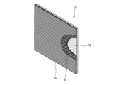
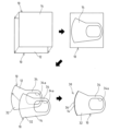
- FIG. 1 is a schematic perspective view of a filter according to one aspect of the present disclosure
- FIG. It is explanatory drawing which shows one aspect
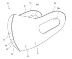
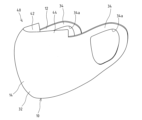
- 1 is a perspective view of a mask according to the first aspect of the present disclosure;
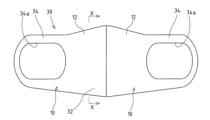
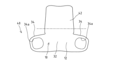
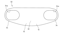
- FIG. It It is a rear view which shows the mask of a 1st aspect.
- It is a front view which shows the mask of a 1st aspect.
- It is a side view which shows the mask of a 1st aspect.
- FIG. 6 is a cross-sectional view taken along the line XX of FIG.
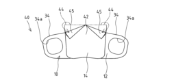
- FIG. 10 is a schematic perspective view of a mask according to a second aspect of the present disclosure
- Fig. 10 is a rear view of the mask according to the second aspect of the present disclosure, with the folded portion in the deployed position
- Fig. 10 is a rear view of the mask according to the second aspect of the present disclosure, with the folded portion in the folded position
- FIG. 11 is a schematic perspective view showing another example of the mask of the second aspect
- FIG. 11 is a rear view showing another example of the mask of the second aspect, in which the folded portion is in the unfolded posture
- FIG. 10 is a schematic perspective view of a mask according to a second aspect of the present disclosure
- Fig. 10 is a rear view of the mask according to the second aspect of the present disclosure, with the folded portion in the folded position
- FIG. 11 is a schematic perspective view showing another example of the mask of the second aspect
- FIG. 11 is a rear view showing another example of the mask of the second aspect, in which the folded portion is in the unfolded posture
- FIG. 11 is a rear view showing another example of the mask of the second aspect, in which the folded portion is in the folded posture; It is a rear view which shows another example of the mask of the 2nd aspect, and the seal
- FIG. 11 is a rear view of a mask according to a third aspect of the present disclosure.
- a filter 10 as one aspect of the present disclosure includes a foam layer 12 that is a resin foam, a fabric layer 14, and fibers disposed between the foam layer 12 and the fabric layer 14. layer 16, and a laminated structure.
- the cloth layer 14 is made of a sheet of cloth made from fibers or threads.
- the fiber layer 16 is an assembly of fibers.
- the filter 10 can be used for removing foreign substances such as pollen and bacteria from the fluid passing through it, and is particularly suitable for removing pollen and bacteria from the air.
- the filter 10 can be used, for example, by being attached to a mask or an air inlet of an air purifier or an air conditioner, and is particularly suitable for masks. It is preferable that the filter 10 has flexibility and flexibility that allows bending deformation, especially for use as a mask.
- the filter 10 has air permeability.
- the air permeability of the filter 10 is preferably 10 cm 3 /(cm 2 ⁇ sec) or more, more preferably 15 cm 3 /(cm 2 ⁇ sec) or more, and 20 cm 3 /(cm 2 ⁇ sec) or more. and more preferably 25 cm 3 /(cm 2 ⁇ sec) or more.
- the air permeability of the filter 10 is preferably 600 cm 3 /(cm 2 ⁇ sec) or less in relation to the foreign matter collection efficiency. With the filter 10 having the air permeability within the above range, it is possible to ensure good foreign matter trapping efficiency and moderate air permeability.
- the air permeability in the present disclosure is a value measured using the method described in JIS L1096-7: 2010 “Fabric test method for woven and knitted fabrics: A method (Fragile method)” for a measurement object with a predetermined thickness. be.
- the elongation rate of the filter 10 (JIS K6400-5:2004 dumbbell No. 2 type) is preferably 80% to 500%, more preferably 150% to 500%, and even more preferably 200% to 450%. .
- the filter 10 is easily deformed and can be attached following the shape of the installation location.
- the peripheral edges of the mask are in close contact with the face, making it difficult for a gap to form between the mask and the face.
- it stretches appropriately according to the movement of the mouth, etc., and can reduce the burden when worn. If the ear hook portion of the mask is formed with the filter 10 having the elongation rate within the above range, the ear hook portion will not easily break and the burden on the ear can be reduced.
- the resin foam of the foam layer 12 examples include polyurethane foam, polyolefin foam such as polyethylene and polypropylene, and melamine foam.
- Polyurethane foam is preferable as a resin foam because it has excellent elongation and strength and can have a high open area ratio. A resin foam having excellent elongation and strength can improve fit to the face when the filter 10 is used as a mask. In addition, if the resin foam has a high open area ratio, breathability can be ensured to suppress suffocation.
- a soft resin foam is preferable as the foam layer 12 because it is soft and has resilience.
- resin foams include slab molding, extraction methods, and other molding methods.
- Resin foam is a film-removed product in which the cell walls (films) between adjacent cells are removed to leave only the skeleton, or a continuous structure or semi-connected structure in which each cell wall (film) has holes. Structures can be used.
- the film-removed product can be obtained by a known film-removal treatment, for example, a method of dissolving the cell walls with a solvent, a method of destroying the cell walls by explosion, or the like.
- the filter 10 can complement the weak physical properties of the resin foam with the cloth layer 14 or the fiber layer 16, there is a wide range of resin foams that can be selected.
- resin foams for example, in the case of polyurethane foam, if polyether-based foam, which is superior in water resistance (resistance to moist heat aging) compared to polyester-based foam, is used, mechanical strength is inferior to that of polyester-based foam, but the presence of the cloth layer 14 can ensure mechanical strength.
- polyether-based foam which is superior in water resistance (resistance to moist heat aging) compared to polyester-based foam, is used, mechanical strength is inferior to that of polyester-based foam, but the presence of the cloth layer 14 can ensure mechanical strength.
- polyether-based and polyester-based polyurethane foams can be used.
- the resin foam has air permeability.
- the air permeability of the resin foam is preferably 10 cm 3 /(cm 2 ⁇ sec) or more, more preferably 15 cm 3 /(cm 2 ⁇ sec) or more, and more preferably 20 cm 3 /(cm 2 ⁇ sec) or more. It is more preferable if there is, and it is particularly preferable if it is 25 cm 3 /(cm 2 ⁇ sec) or more.
- the air permeability of the resin foam is preferably 600 cm 3 /(cm 2 ⁇ sec) or less in relation to the efficiency of capturing foreign matter. In the filter 10, even if the air permeability of the foam layer 12 is increased, the other layers can ensure foreign matter collection efficiency. may
- the number of cells of the resin foam (JIS K6400-1:2004 Annex 1 (reference)) is preferably 30 cells/25 mm to 150 cells/25 mm, and more preferably 40 cells/25 mm to 110 cells/25 mm. .
- the number of cells of the resin foam is within the above range, appropriate air permeability can be ensured.
- the filter 10 is used for a mask, it is possible to suppress rough feeling on the skin and to provide an appropriate frictional resistance for suppressing slippage of the mask.
- the filter 10 is used as a mask, it is possible to secure adequate breathability, so that it is possible to reduce suffocation and stuffiness, and a good feeling of wearing can be obtained.
- the elongation rate of the resin foam (JIS K6400-5: 2004 Dumbbell No. 2 type) is preferably 80% to 500%, more preferably 150% to 500%, and further preferably 200% to 450%. preferable.
- the filter 10 is easily deformed and can be attached following the shape of the installation location.
- the filter 10 is used as a mask, the peripheral edges of the mask are in close contact with the face, making it difficult for a gap to form between the mask and the face. In addition, it stretches appropriately according to the movement of the mouth, etc., and can reduce the burden when worn.
- the filter 10 forms an ear hook, the ear hook is less likely to break and the burden on the ear can be reduced.
- the density of the resin foam (JIS K7222:2005) is preferably 10 kg/m 3 to 100 kg/m 3 , more preferably 10 kg/m 3 to 85 kg/m 3 .
- the density of the resin foam is within the above range, the weight of the filter 10 can be reduced. And when the filter 10 is used as a mask, the burden of wearing it can be reduced.
- the hardness (25% ILD) of the resin foam is preferably 40N to 400N, more preferably 60N to 300N. When the hardness of the resin foam is within the above range, appropriate strength can be ensured.
- the filter 10 is used as a mask, the peripheral edges of the mask are in close contact with the face, making it difficult for a gap to form between the mask and the face.
- the filter 10 forms an ear hook, the ear hook is difficult to cut.
- the above-mentioned hardness is according to the JIS K6400-2:2012 hardness test method when a flat disk pressure plate with a diameter of 200 mm is compressed by 25% (D method).
- the thickness of the foam layer 12 is preferably 0.8 mm to 3 mm. When the thickness of the foam layer 12 is within the above range, the bulkiness of the filter 10 can be suppressed, so that it is easy to handle and the cost of the filter 10 can be suppressed.
- the resin foam it is preferable to use a clean-treated product that has been treated to reduce odors derived from chemical substances such as foaming agents and has excellent cleanliness.
- the clean treatment for example, the resin foam is washed with water, etc., or heat-treated (for example, 70 to 120 ° C., 30 to 120 minutes) to deodorize, etc. Chemical substances remaining in the resin foam are removed. can be removed.
- the amount of volatile organic compounds (VOC) measured in accordance with VDA-278 (total VOC amount) in the resin foam is desirably 1000 ppm or less. A total VOC content of 400 ppm or less is more preferable because of less odor and excellent cleanness.
- Fabric layer 14 can be a fabric such as knitted, woven, non-woven, or felt.
- fibers constituting the cloth those composed of chemical fibers such as polyethylene, polypropylene, nylon, urethane, and rayon, and those composed of natural fibers such as cotton and wool can be used.
- Polyester fibers are preferable from the standpoint of durability because they are less susceptible to discoloration due to ultraviolet rays.
- a cloth having low hygroscopicity is convenient for washing and drying the filter 10 .
- cloth made of cotton or rayon is water absorbent, so it may be used when the filter 10 is required to absorb moisture or retain moisture.
- the fabric may be an antimicrobial fabric having antimicrobial properties such as by antimicrobial treatment.
- the cloth may be one in which surface fibers are raised.
- the cloth it is possible to use fabrics that are structurally stretchable depending on how they are woven or knitted, or so-called stretch fabrics that are stretchable by using elastic fibers that have stretchability.
- stretchable plain weave, twill weave, and jacquard weave are preferred.
- warp knitting, weft knitting, and others can be used. Warp knitting includes tricot, double raschel, etc., and weft knitting includes circular knitting and jersey knitting. be done. Knitted fabrics are preferred because they are more stretchable than woven fabrics and non-woven fabrics.
- the web may be formed by any of a dry method, a spunbond method, a meltblown method, an airlaid method, and the like. From the viewpoint of the efficiency of capturing fine foreign matter such as bacteria, a nonwoven fabric by a meltblown method (meltblown nonwoven fabric) or a nonwoven fabric by a spunbond method (spunbond nonwoven fabric) is preferable.
- the nonwoven fabric may be formed by a chemical bond method, a thermal bond method, a needle punch method, a hydroentanglement method (spunlace), or the like. A hydroentanglement method and a needle punch method are preferable.
- the elongation percentage of the cloth is preferably 50% to 500%.
- the stretchability of the foam layer 12 is less likely to be hindered by the fabric layer 14, and the stretchability of the filter 10 can be improved.
- the filter 10 is used as a mask, it stretches appropriately according to the movement of the mouth, etc., and can reduce the burden when worn. Further, when the ear hook portion of the mask is formed with the filter 10, the ear hook portion is difficult to cut and the burden on the ear can be reduced. It should be noted that it is preferable to use a cloth having a lower elongation rate than the resin foam, since excessive elongation of the resin foam can be suppressed, plastic deformation of the resin foam can be prevented, and the filter 10 can be strengthened.
- the air permeability of the fabric is preferably 10 cm 3 /(cm 2 ⁇ sec) or more, more preferably 15 cm 3 /(cm 2 ⁇ sec) or more, and 20 cm 3 /(cm 2 ⁇ sec) or more. More preferably, it is particularly preferably 25 cm 3 /(cm 2 ⁇ sec) or more.
- the air permeability of the cloth is preferably set to 150 cm 3 /(cm 2 ⁇ sec) or less in relation to the efficiency of trapping foreign matter. A fabric having air permeability within the above range can ensure good foreign matter trapping efficiency and appropriate air permeability.
- the filter 10 when used for a mask, it is possible to ensure adequate breathability, so that it is possible to reduce the feeling of suffocation and to obtain a good wearing feeling. Further, if the fabric has air permeability within the above range, when the filter 10 is used as a mask, a good foreign matter collection efficiency can be obtained. As described above, it is preferable to use a fabric having air permeability within the above range, because it is possible to achieve both ease of breathing and good foreign matter collection efficiency. In the filter 10, even if the air permeability of the fabric layer 14 is increased, the fiber layer 16 can ensure the foreign matter collection efficiency. may
- the thickness of the cloth layer 14 is preferably 0.1 mm to 0.4 mm. As the fabric layer 14 becomes thicker, the efficiency of trapping foreign matter improves, but the pressure loss of the air passing through itself increases (the air permeability decreases). The thinner the cloth layer 14 is, the lower the efficiency of trapping foreign matter, but the lower the pressure loss of the air passing through itself (the higher the air permeability). When the thickness of the fabric layer 14 of the filter 10 is within the above range, moderate air permeability can be obtained. Further, when the thickness of the cloth layer 14 is within the above range, the bulkiness of the filter 10 can be suppressed.
- the fiber layer 16 is an aggregate of fibers 18 .
- the fiber layer 16 may be formed by processing fibers into a sheet such as a non-woven fabric. It is preferable because it spreads well. In addition, it is preferable that the fibers of the fiber layer 16 are not bonded to each other with an adhesive because the fiber layer 16 has good elongation.
- the fibers may be formed by any of melt spinning, wet spinning, and dry spinning, but electrospinning, which is a type of melt spinning, is preferred because fine fibers can be obtained.
- the fiber layer 16 is composed of micro-sized fibers with a fiber diameter of 1 ⁇ m to 1000 ⁇ m or nano-sized fibers with a fiber diameter of 1 nm to 1000 nm (1 ⁇ m).
- the fibrous layer 16 is preferably made of nano-sized fibers (nanofibers) from the viewpoint of foreign matter collection efficiency. From the viewpoint of productivity, the fiber layer 16 is preferably micro-sized fibers of 1 ⁇ m to 1000 ⁇ m.
- the fiber diameter of the fiber is preferably from 10 nm to 100 ⁇ m, more preferably from 10 nm to 50 ⁇ m, and even more preferably from 10 nm to 30 ⁇ m, from the viewpoint of practicality of collecting foreign matter.
- the thickness is preferably 10 nm to 800 nm, more preferably 10 nm to 500 nm, and even more preferably 10 nm to 100 nm.
- the fiber diameter of the fiber is within the above range, it is possible to secure the trapping of foreign substances and appropriate air permeability.
- the fibers forming the fiber layer 16 have a smaller fiber diameter than the fibers and threads forming the fabric layer 14 . By doing so, the cloth layer 14 can be made relatively strong, and the fiber layer 16 can collect microscopic foreign substances such as bacteria that are difficult to collect with the cloth layer 14 .
- Fiber materials include, for example, thermoplastic fluororesins such as polyvinylidene fluoride, thermoplastics such as polystyrene, polycarbonate, poly(meth)acrylate, polyvinyl chloride, polyethylene terephthalate, nylon-6,6, and nylon-4,6. Resin, polyurethane, polyvinyl alcohol, polylactic acid, polycaprolactone, polyethylene glycol, polyethylene-vinyl acetate copolymer, polyethylene-vinyl alcohol copolymer, polyethylene oxide, biodegradable polymer such as collagen, polyacrylonitrile, polyamide, polyaniline , paraamide, polyvinyl acetate, acetyl cellulose (acetate), and the like.
- thermoplastic fluororesins such as polyvinylidene fluoride
- thermoplastics such as polystyrene, polycarbonate, poly(meth)acrylate, polyvinyl chloride, polyethylene terephthalate, nylon-6,6, and nylon-4,6
- Polyurethane fibers are preferable because they have good adhesion to the foam layer 12 and have good elongation. If the fiber layer 16 has good elongation, the foam layer 12 and the fabric layer 14 can follow the elongation well, and when the filter is used as a mask, for example, it can easily fit the face.
- the air permeability of the fiber layer 16 is preferably 10 cm 3 /(cm 2 ⁇ sec) or more, more preferably 15 cm 3 /(cm 2 ⁇ sec) or more, and more preferably 20 cm 3 /(cm 2 ⁇ sec) or more. It is more preferable if there is, and it is particularly preferable if it is 25 cm 3 /(cm 2 ⁇ sec) or more.
- the air permeability of the fiber layer 16 is preferably set to 150 cm 3 /(cm 2 ⁇ sec) or less in relation to the efficiency of capturing foreign matter. When the air permeability of the fiber layer 16 is within the above range, the filter 10 can ensure foreign matter collection efficiency and air permeability. When the filter 10 is used for a mask, it is possible to reduce suffocation due to moderate ventilation, and a good wearing feeling can be obtained. In addition, the filter 10 provides good foreign matter collection efficiency.
- the air permeability of the fiber layer 16 is preferably set lower than that of the foam layer 12. By doing so, the fiber layer 16 compensates for the foreign matter collection efficiency that cannot be obtained with the foam layer 12 without impairing the goodness of the foam layer 12 such as flexibility and elongation, so that the filter 10 has a good foreign matter collection efficiency. Collection efficiency is obtained. Moreover, it is preferable to set the air permeability of the fiber layer 16 to be lower than that of the fabric layer 14 . By doing so, the fiber layer 16 compensates for the foreign matter collection efficiency that cannot be obtained with the cloth layer 14 without impairing the goodness of the cloth layer 14 such as flexibility and elongation, and good foreign matter collection in the filter 10 is achieved. Efficiency is obtained.
- the fiber basis weight of the fiber layer 16 is preferably 0.10 g/m 2 to 10 g/m 2 , more preferably 0.10 g/m 2 to 5 g/m 2 . By doing so, the fiber layer 16 can secure foreign matter collection efficiency and air permeability.
- the basis weight of the fibers of the fiber layer 16 can also be set according to the difference in objects to be collected for foreign matter and the fiber diameter of the fiber layer 16 . For example, when the fiber layer 16 has a large fiber diameter, it is 0.5 g/m 2 to 10 g/m 2 , 0.5 g/m 2 to 5 g/m 2 , 1 g/m 2 to 3 g/m 2 . can do.
- the fiber layer 16 with a small fiber diameter the ⁇ 0.6 g/m 2 . In this case, it is effective for collecting small-sized foreign substances such as bacteria and viruses.
- the contaminant collection efficiency of the filter 10 can be determined by BFE (Bacterial Filtration Efficiency).
- BFE is a value measured in accordance with JIS L1912:1997 (Appendix) (Methods for Testing Nonwoven Fabrics for Medical Use), and a larger value indicates that there is no change in the total colony count of Staphylococcus aureus. That is, it refers to the percentage obtained by subtracting the total colony number (B) when the sample was set from the total colony number (A) of the control and dividing the difference by the total colony number (A) of the control.
- BFE (%) ⁇ (A) - (B) ⁇ ⁇ (A) x 100
- the BFE of the filter 10 is preferably 70% or higher, more preferably 80% or higher, even more preferably 90% or higher, and particularly preferably 95% or higher.
- a sheet of resin foam that forms the foam layer 12 is prepared.
- a cloth for the cloth layer 14 is prepared.
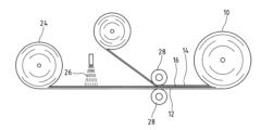
- a fiber layer 16 is formed by applying fibers 18 to one surface of the resin foam by an electrospinning method.
- the equipment used for electrospinning comprises, for example, a DC high voltage power supply, an infusion pump, a needle syringe and a metal collector 22 .
- the polymer solution is injected from the nozzle 20 of a needle syringe toward one surface of the resin foam.
- the nozzle 20 and the metal collector 22 are charged oppositely, and when the polymer solution is sprayed from the nozzle 20, the fibers 18 formed from the polymer solution are formed on the resin foam placed on the metal collector 22. After application, fine fibers 18 are gradually piled up to form a fiber layer 16 .
- the fiber diameter of the fibers 18 can be adjusted by adjusting the distance from the nozzle 20 of the needle syringe to the resin foam, the amount of the polymer solution injected from the nozzle 20, the voltage, and the like.
- the fiber layer 16 is joined to the foam layer 12 by entangling the fibers 18 around the resin foam. Thus, an intermediate sheet 24 with a fiber layer 16 on one side of the foam layer 12 is obtained.
- a method of joining the intermediate sheet 24 and the cloth includes frame lamination and adhesion using a hot-melt adhesive.
- a hot-melt adhesive As an adhesion method using a hot-melt adhesive, the intermediate sheet 24 and the cloth are pasted together by sandwiching an adhesive layer such as a hot-melt adhesive or applying the adhesive by a roll coater or spray coating.
- a non-woven hot-melt sheet may be sandwiched between the intermediate sheet 24 and the cloth, and the hot-melt sheet may be melted and adhered (dry lamination) by heating and press-bonding them.
- thermoplastic hot-melt materials such as polyamide, polyvinyl alcohol, and polyester, and moisture-curing hot-melt materials can be used.
- a fibrous hot-melt adhesive 26 may be applied as shown in FIG.
- the fibrous hot-melt adhesives 26 intersect each other and are arranged in a mesh-like manner, creating gaps between the fibrous hot-melt adhesives 26 .
- the fibrous hot-melt adhesive 26 By bonding the intermediate sheet 24 and the cloth with the fibrous hot-melt adhesive 26, the bonded portion where the cloth layer 14 and the fiber layer 16 are bonded and the cloth layer 14 and the fiber layer 16 are bonded in the filter 10.
- a non-bonded portion that is not bonded is formed. Since the non-bonded portion is easier to ventilate than the bonded portion, there is an advantage that the air permeability of the filter 10 can be improved.
- the fibrous hot melt adhesive 26 preferably has a diameter of 10 ⁇ m to 600 ⁇ m. When the diameter of the fibrous hot-melt adhesive 26 is within the above range, it is possible to easily form a non-bonded portion and improve breathability while ensuring an appropriate bonding strength at the bonded portion.
- the amount of fibrous hot-melt adhesive 26 to be applied is preferably 5 g/m 2 to 100 g/m 2 . When the amount of the fibrous hot-melt adhesive 26 to be applied is within the above range, it is possible to easily form a non-bonded portion and improve breathability while ensuring an appropriate bonding strength at the bonded portion.
- the fibers 18 are applied to the resin foam, but the fibers 18 may be applied to the cloth.
- the intermediate sheet in which the fiber layer 16 and the cloth layer 14 are laminated and the resin foam are laminated by the bonding method described above.
- the fibers 18 may be applied to both the resin foam and the cloth.
- the intermediate sheet in which the fiber layer 16 and the foam layer 12 are laminated and the intermediate sheet in which the fiber layer 16 and the cloth layer 14 are laminated are laminated by the bonding method described above.
- the filter 10 Since the filter 10 has a multi-layer structure, the synergy of the physical properties of the layers improves the function, and the layers complement each other to obtain functions that cannot be obtained with a single layer. Specifically, since the filter 10 includes the fiber layer 16 between the foam layer 12 and the cloth layer 14, the efficiency of collecting foreign matter is improved, and the passage of foreign matter at the level of bacteria can be properly blocked. Since the fiber layer 16 can ensure good foreign matter collection efficiency, the degree of freedom in selecting the foam layer 12 and the fabric layer 14 is increased, and the function of the filter 10 can be improved by the foam layer 12 and the fabric layer 14 . Since the fiber layer 16 is placed between the foam layer 12 and the cloth layer 14 and protected, even if the fiber 18 is an aggregate, the fiber 18 can be prevented from becoming fuzzy.
- the fiber layer 16 is an aggregate of the fibers 18, the foam layer 12 and the fabric layer 14 have good followability to deformation such as bending and elongation. Even if the filter 10 has the fiber layer 16 that improves the foreign matter collection efficiency, the fiber layer 16 does not easily prevent the deformation of the foam layer 12 and the cloth layer 14. Therefore, the easiness of bending and stretching as a whole is improved. Ease of deformation can be secured. When the cloth layer 14 is made of a knitted fabric, the cloth layer 14 can be stretched well, so that the easiness of deforming the filter 10, such as easiness of bending and easiness of stretching, can be improved.
- the fiber layer 16 has a structure in which the fibers 18 are entwined to join adjacent layers, there is no film or the like that hinders ventilation at the joint surface unlike adhesion by adhesive or welding by frame lamination.
- the air permeability of the filter 10 can be improved.
- the fiber layer 16 and the adjacent layer are bonded, the fiber layer 16 and the adjacent layer are bonded by having a non-bonded portion where the fiber layer 16 and the adjacent layer are not bonded.
- the air permeability of the filter 10 can be improved by the non-bonded portion, which is easier to ventilate than the portion.
- the filter 10 can make it difficult for the expansion and contraction of the foam layer 12 to be hindered due to the presence of the cloth layer 14 and the fiber layer 16 .
- the filter 10 preferably exhibits the stretchability specific to the resin foam.
- the elongation rate of the resin foam may become too large. In this case, if a cloth having a lower elongation rate than the resin foam is used, excessive elongation of the filter 10 can be suppressed, and the strength of the filter 10 can be improved while ensuring air permeability.
- the filter 10 has a fiber layer 16 that has a high foreign matter collection efficiency and does not adversely affect deformation such as expansion and contraction of other layers, the foam layer 12 and the cloth layer 14 have a high degree of freedom and can collect foreign matter. Functionality can be improved while ensuring efficiency.
- the fibers 18 are applied to one surface of the resin foam and/or one surface of the cloth, and the fiber layer 16 is formed by the assembly of the fibers 18.
- the fibers 18 are applied by an electrospinning method, the fiber layer 16 can be joined by the entanglement of the fibers 18 without using an adhesive or welding, so that the air permeability of the filter 10 can be improved.
- the fibers 18 are provided by the electrospinning method, the fibers 18 can be made finer, so that the efficiency of the filter 10 in collecting foreign matters can be improved.
- the filter 10 can be easily obtained by laminating the resin foam, the fiber layer 16 and the cloth such that the fiber layer 16 is between the resin foam and the cloth.
- the fibrous hot-melt adhesive 26 when joining the fiber layer 16 and the cloth or resin foam, a non-bonded portion can be easily formed between the bonded portions by the fibrous hot-melt adhesive 26.
- the air permeability of the obtained filter 10 can be improved.
- the filter is limited to the configuration described above, and various changes including the following are possible. In addition, it is not limited to the structure illustrated concretely.
- the layer configuration of the filter is not limited to the three layers described above, and may be four or more layers.
- another fabric layer may be placed over the foam layer 12 .
- another fabric layer arranged on the opposite side of the fabric layer 14 laminated to the fiber layer 16 is preferably made of a fabric having higher air permeability than the foam layer 12 .
- Another foam layer may also be placed over the fabric layer 14 .
- another foam layer arranged on the opposite side of the foam layer 12 laminated on the fiber layer 16 can be made of the same resin foam as the foam layer 12 .
- some or all of the foam layer 12, fabric layer 14 and fiber layer 16 may be composed of two or more layers of the same or different materials.
- the fiber layer 16 may be formed of a nonwoven fabric instead of the electrospinning method.
- a nonwoven fabric produced by a meltblown method meltblown nonwoven fabric
- a nonwoven fabric produced by a spunbond method spunbond nonwoven fabric
- the filter may have a configuration in which two layers (for example, the foam layer 12 and the fabric layer 14), front and back, sandwich and hold a layer such as the fiber layer 16 disposed in the middle.
- the foam layer 12 and the fabric layer 14 may be bonded together, and the fiber layer may be sandwiched and held without bonding.
- both the front and back layers are resin foams
- the fiber layers may be sandwiched and held by joining the resin foams together by heat sealing, adhesion, sewing, or the like.
- FIG. 1 the wearer's side when wearing a mask may be called the back side, and the side opposite to the wearer may be called the front side.
- the mask 30 of the first mode includes a mask main body 32 that covers part of the face including the mouth, and ear hooks 34 provided on the side edges of the mask main body 32.
- the mask main body 32 is sized to cover the central part of the wearer's face, from the bridge of the nose to the chin via the nostrils and mouth, and both left and right cheeks.
- the ear hooking portion 34 is formed with an ear hooking hole 34a for hooking on the ear when worn.
- the mask main body 32 is formed at least by the filter 10 described above.
- the mask main body 32 and the ear hooks 34 are made of the same filter 10 .
- the foam layer 12 is oriented toward the back side, which contacts the wearer's face, and the fabric layer 14 is oriented toward the front side (see FIG. 8).
- the mask main body 32 of the first mode is formed by joining two filters 10,10.
- the left-right half of the mask body 32 and the ear hooks 34 connected to one side of the mask body 32 are formed of one filter 10 .
- the mask main body 32 has a three-dimensional shape that protrudes toward the front side toward the center in the vertical direction.
- the mask main body portion 32 is formed on the front side toward the central portion in the left-right direction. It becomes a three-dimensional shape that becomes convex.
- the mask 30 can be manufactured, for example, as follows. As shown in FIG. 9, the two filters 10 with the foam layers 12 facing each other are punched by a Thomson blade or the like to form a shape corresponding to the half of the mask 30 in the left-right direction. The mask 30 is obtained by joining the edges of the two filters, which are the central portions in the left-right direction of the mask main body portion 32 .
- the method of joining the filter 10 includes a heat sealing method by hot press molding, ultrasonic fusion, joining by adhesive, joining by sewing, and the like.
- the mask 30 Since the mask 30 is composed of the filter 10 described above, it has a good foreign matter collection efficiency.
- the cloth layer 14 has a texture peculiar to cloth, and it is possible to attach colors, pictures, patterns, etc., which are difficult to be applied to the resin foam, so that the design of the mask 30 can be improved.
- the front side of the mask 30 can be protected by the cloth layer 14, which is superior in abrasion resistance and weather resistance to the resin foam. Due to the unique flexibility and elongation of the resin foam placed on the back side of the mask 30, the burden on the skin can be reduced, and the peripheral edge of the mask body 32 can improve the ability to follow movements of the mouth.
- the foam layer 12 arranged on the back side of the mask 30 has better air permeability than the other layers, it is possible to suppress sticking of the mask main body 32 to the mouth and nose due to breathing, and it is difficult to get stuffy and easy to breathe. .
- the filter 10 the commercial value of the mask 30 can be improved.
- the mask main body part 32 of the mask 30 is composed of the filter 10 having an appropriate elongation rate, the peripheral edge of the mask main body part 32 is in close contact with the face, making it difficult for a gap to form between the mask body part 32 and the face. Intrusion of foreign matter can be prevented. In addition, since the mask main body 32 deforms following the movement of the mouth, etc., the burden of wearing the mask 30 can be reduced.
- the mask 30 not only the mask main body 32 but also the ear hooks 34 connected to the sides of the mask main body 32 are formed of the same filter 10 as the mask main body 32. As a result, the mask 30 tends to chip the ear hooks 34 against the ears due to moderate expansion and contraction. In addition, the mask 30 can reduce the burden on the ears when worn, and the mask main body 32 can be brought into close contact with the face by moderately pulling the ear hooks 34 .
- the mask main body 32 By forming the mask main body 32 with a plurality of filters 10 like the mask 30 of the first mode, a three-dimensional shape matching the shape of the face can be obtained.
- the mask 30 By making the mask 30 have a three-dimensional shape, it is possible to improve the adhesion to the face, so that even if the mouth is moved, a gap is hardly formed between the mask and the face, and foreign matter can be prevented from entering through the gap.
- the connecting portion 36 has a curved shape in which the central portion in the vertical direction is convex, the central portion in the horizontal direction of the mask main body portion 32 will move toward the front side of the mask 30 when the two filters 10, 10 are unfolded to the left and right. It is preferable because it becomes an inflated three-dimensional shape.
- the mask is not limited to the above configuration, and various modifications including the following items are possible. In addition, it is not limited to the structure illustrated concretely.
- the mask is configured by combining two laminated sheets, but the entire mask may be configured with one filter 10 as shown in FIGS. Also, three or more filters may be joined together to form a mask.
- a folded portion 42 may be provided contiguously with the upper edge portion of the mask body portion 32 .
- the folded portion 42 is positioned between the unfolded posture (see FIGS. 11 and 14) extending upward from the mask body portion 32 and the folded posture (see FIGS. 12 and 15) in which the mask body portion 32 is folded so as to overlap the back side of the mask body portion 32. It is possible to change the posture with When the folded portion 42 is in the folded posture, a seal portion 44 formed by the folded portion of the folded portion 42 is formed at the upper edge portion of the mask body portion 32 .
- the seal portion 44 may be folded back toward the back side (wearer side) to form an inward folded portion 45 (see FIG. 16).
- the seal portion 44 of the mask 40 makes it difficult for a gap to form between the mask and the face even when the mouth is moved, and foreign matter can be prevented from entering through the gap. In addition, by closing the gap with the sealing portion 44, it is possible to prevent the glasses from being fogged by exhalation. As shown in FIG. 15, if the folding portion 42 is set to have a size that entirely overlaps with the mask main body portion 32, the foreign matter collection efficiency can be improved.
- the folded portion may be provided continuously with the lower edge portion of the mask main body portion, or may be provided at both the lower edge portion and the lower edge portion of the mask main body portion.
- the sealing portion can be formed at the lower edge of the main body by folding back the folded portion, and the gap between the lower edge of the mask main body and the chin can be closed. It can be closed with a seal.
- the mask may be used with the foam layer on the back side and the cloth layer on the front side, or with the foam layer on the front side and the cloth layer on the back side. may By arranging the fabric layer on the back side, it is possible to improve the feel to the skin and suppress the stickiness caused by exhalation.
- ⁇ Foam layer ⁇ Foam A: Flexible polyurethane foam (manufactured by INOAC Corporation, product name: MF-60, polyester polyurethane foam, elongation: 400%, number of cells: 60 / 25 mm, film-removed foam)
- Foam B Flexible polyurethane foam (manufactured by INOAC Corporation, product name: MF-80, polyester polyurethane foam, elongation: 400%, number of cells: 80 / 25 mm, film-removed foam)
- Foam C Flexible polyurethane foam (manufactured by INOAC Corporation, product name: ECS, polyether polyurethane foam, elongation: 180%, number of cells: 40/25 mm, non-film-removed foam)
- Cloth A Stretch ester 50D (material: polyester, crimped multifilament yarn, 50 denier, knitting method: circular knitting, basis weight: 50 g/m 2 )
- Cloth B Nylon sheeting (material: nylon, crimped multifilament yarn, 75 denier, knitting method: sheeting knit, 80 g/m 2 )
- Cloth C Rayon-based spunlace nonwoven fabric (material: rayon, spunlace method (hydroentanglement method), basis weight: 50 g/m 2 )
- Fiber layer ⁇ Fiber A: thermoplastic fluororesin (polyvinylidene fluoride) fiber, fiber diameter (diameter): about 300 nm, basis weight: 0.3 g / m 2 ⁇ Fiber B: thermoplastic fluororesin (polyvinylidene fluoride) fiber, fiber diameter (diameter): about 500 nm, basis weight: 0.6 g / m 2
- the hot-melt adhesive shown in Table 1 is used to join the fabric and the intermediate sheet formed by forming the fiber layer on the foam layer by the electrospinning method.
- the cloth and the resin foam are bonded with the hot-melt adhesive shown in Table 3.
- ⁇ Hot-melt non-woven fabric non-woven hot-melt sheet (material: polyamide, basis weight: 13 g/m 2 )
- ⁇ Fibrous hot-melt moisture-curing hot-melt adhesive (material: polyurethane-based hot-melt, fiber diameter: 20 ⁇ m, coating amount: 15 g/m 2 )
- the air permeability is a value measured using the method described in JIS L1096-7:2010 “Testing method for woven and knitted fabrics: Method A (Fragile method)”.
- BFE is a value obtained by measuring the object to be measured using the method described in JIS L1912:1997 (Appendix) "Method for Testing Nonwoven Fabrics for Medical Use”.
- Example 1 As shown in Tables 1 and 2, it can be seen that the masks of Examples 1 to 12 having fiber layers have a high level of foreign matter collection efficiency. Further, when comparing Example 1 and Example 2, Example 2 bonded with a fibrous hot-melt adhesive exhibits higher air permeability.
Landscapes
- Chemical & Material Sciences (AREA)
- Chemical Kinetics & Catalysis (AREA)
- Respiratory Apparatuses And Protective Means (AREA)
Priority Applications (2)
| Application Number | Priority Date | Filing Date | Title |
|---|---|---|---|
| JP2023556049A JPWO2023073944A1 (https=) | 2021-10-29 | 2021-10-29 | |
| PCT/JP2021/040090 WO2023073944A1 (ja) | 2021-10-29 | 2021-10-29 | フィルタおよびその製造方法、マスク |
Applications Claiming Priority (1)
| Application Number | Priority Date | Filing Date | Title |
|---|---|---|---|
| PCT/JP2021/040090 WO2023073944A1 (ja) | 2021-10-29 | 2021-10-29 | フィルタおよびその製造方法、マスク |
Publications (1)
| Publication Number | Publication Date |
|---|---|
| WO2023073944A1 true WO2023073944A1 (ja) | 2023-05-04 |
Family
ID=86157611
Family Applications (1)
| Application Number | Title | Priority Date | Filing Date |
|---|---|---|---|
| PCT/JP2021/040090 Ceased WO2023073944A1 (ja) | 2021-10-29 | 2021-10-29 | フィルタおよびその製造方法、マスク |
Country Status (2)
| Country | Link |
|---|---|
| JP (1) | JPWO2023073944A1 (https=) |
| WO (1) | WO2023073944A1 (https=) |
Citations (6)
| Publication number | Priority date | Publication date | Assignee | Title |
|---|---|---|---|---|
| JPS60144921U (ja) * | 1984-03-06 | 1985-09-26 | 日東電工株式会社 | 集塵機用フイルタ− |
| JP2001310107A (ja) * | 2000-04-01 | 2001-11-06 | Andreas Stihl:Fa | 形状安定性のあるフイルター要素 |
| JP2008509020A (ja) * | 2004-08-03 | 2008-03-27 | アドバンスド・デザイン・コンセプト・ゲゼルシヤフト・ミツト・ベシユレンクテル・ハフツング | 通気性弾性複合体 |
| JP2011502756A (ja) * | 2007-11-12 | 2011-01-27 | エムゲーエフ グートシェ ウント コムパニー ゲゼルシャフト ミット ベシュレンクテル ハフツング−ベトリーブス−コマンディート ゲゼルシャフト | ろ過媒体 |
| JP2019094604A (ja) * | 2017-11-13 | 2019-06-20 | スリーエム イノベイティブ プロパティズ カンパニー | マスク及びマスクを製造する方法 |
| KR102199955B1 (ko) * | 2020-06-01 | 2021-01-11 | 주식회사 피앤씨랩스 | 습도조절기능을 갖는 안면마스크 제조용 다층 구조의 부직포 시트 및 이를 이용한 안면 마스크 |
Family Cites Families (2)
| Publication number | Priority date | Publication date | Assignee | Title |
|---|---|---|---|---|
| JP7404112B2 (ja) * | 2020-03-10 | 2023-12-25 | 株式会社イノアックコーポレーション | マスクとその製造方法 |
| JP2021167493A (ja) * | 2020-04-08 | 2021-10-21 | 株式会社アイケー | マスク |
-
2021
- 2021-10-29 JP JP2023556049A patent/JPWO2023073944A1/ja active Pending
- 2021-10-29 WO PCT/JP2021/040090 patent/WO2023073944A1/ja not_active Ceased
Patent Citations (6)
| Publication number | Priority date | Publication date | Assignee | Title |
|---|---|---|---|---|
| JPS60144921U (ja) * | 1984-03-06 | 1985-09-26 | 日東電工株式会社 | 集塵機用フイルタ− |
| JP2001310107A (ja) * | 2000-04-01 | 2001-11-06 | Andreas Stihl:Fa | 形状安定性のあるフイルター要素 |
| JP2008509020A (ja) * | 2004-08-03 | 2008-03-27 | アドバンスド・デザイン・コンセプト・ゲゼルシヤフト・ミツト・ベシユレンクテル・ハフツング | 通気性弾性複合体 |
| JP2011502756A (ja) * | 2007-11-12 | 2011-01-27 | エムゲーエフ グートシェ ウント コムパニー ゲゼルシャフト ミット ベシュレンクテル ハフツング−ベトリーブス−コマンディート ゲゼルシャフト | ろ過媒体 |
| JP2019094604A (ja) * | 2017-11-13 | 2019-06-20 | スリーエム イノベイティブ プロパティズ カンパニー | マスク及びマスクを製造する方法 |
| KR102199955B1 (ko) * | 2020-06-01 | 2021-01-11 | 주식회사 피앤씨랩스 | 습도조절기능을 갖는 안면마스크 제조용 다층 구조의 부직포 시트 및 이를 이용한 안면 마스크 |
Also Published As
| Publication number | Publication date |
|---|---|
| JPWO2023073944A1 (https=) | 2023-05-04 |
Similar Documents
| Publication | Publication Date | Title |
|---|---|---|
| JP4099394B2 (ja) | 伸縮可能なフェースマスク | |
| JP4684554B2 (ja) | 両面柔軟弾力性構成部分を用いた吸収性物品 | |
| KR100655806B1 (ko) | 플라스틱 복합 시이트 및 그 제조 방법 | |
| JP5615713B2 (ja) | 防塵衣服 | |
| JP2023528162A (ja) | 耐久性があり洗浄可能な高性能濾過媒体としての/のための多層布およびその組み立て方法 | |
| JP2016069787A (ja) | 衛生マスク | |
| JP7404112B2 (ja) | マスクとその製造方法 | |
| US20220219105A1 (en) | Nanofiber filter material and resperatory system and air filtering article | |
| JPH09192248A (ja) | マスク | |
| WO2023073944A1 (ja) | フィルタおよびその製造方法、マスク | |
| JPH06328601A (ja) | 通気性シート状構造体およびその製造方法 | |
| JP7699912B2 (ja) | マスク | |
| US10603830B2 (en) | Polymeric netting with ribbons and strands, and methods of making the same | |
| JP2022029545A (ja) | マスク | |
| JP2002144461A (ja) | 複合シート | |
| US11583014B1 (en) | Ultra-light nanotechnology breathable gowns and method of making same | |
| CN101560734A (zh) | 隔菌防螨纺织品及其生产方法和装置 | |
| CN101227953A (zh) | 口罩 | |
| WO2019223360A1 (zh) | 多层式弹性透气材料结构 | |
| KR102566091B1 (ko) | 습도를 제어하는 안면마스크 제조용 다층 구조의 부직포 시트 및 이를 이용한 안면마스크 | |
| JP2022018011A (ja) | マスク | |
| US20210362082A1 (en) | Face mask with filter medium from multicomponent filaments | |
| JP2934271B2 (ja) | 貼布材 | |
| JP7628170B2 (ja) | 軟質ポリエーテルウレタンフォームとウレタンマスク | |
| KR102345981B1 (ko) | 마스크 및 이의 제조방법 |
Legal Events
| Date | Code | Title | Description |
|---|---|---|---|
| 121 | Ep: the epo has been informed by wipo that ep was designated in this application |
Ref document number: 21962485 Country of ref document: EP Kind code of ref document: A1 |
|
| WWE | Wipo information: entry into national phase |
Ref document number: 2023556049 Country of ref document: JP |
|
| NENP | Non-entry into the national phase |
Ref country code: DE |
|
| 122 | Ep: pct application non-entry in european phase |
Ref document number: 21962485 Country of ref document: EP Kind code of ref document: A1 |