WO2023068198A1 - 保護用テープ部材及びワイヤハーネス - Google Patents
保護用テープ部材及びワイヤハーネス Download PDFInfo
- Publication number
- WO2023068198A1 WO2023068198A1 PCT/JP2022/038411 JP2022038411W WO2023068198A1 WO 2023068198 A1 WO2023068198 A1 WO 2023068198A1 JP 2022038411 W JP2022038411 W JP 2022038411W WO 2023068198 A1 WO2023068198 A1 WO 2023068198A1
- Authority
- WO
- WIPO (PCT)
- Prior art keywords
- tape member
- wire
- base material
- flat portion
- adhesive layer
- Prior art date
- Legal status (The legal status is an assumption and is not a legal conclusion. Google has not performed a legal analysis and makes no representation as to the accuracy of the status listed.)
- Ceased
Links
Images



Classifications
-
- H—ELECTRICITY
- H01—ELECTRIC ELEMENTS
- H01B—CABLES; CONDUCTORS; INSULATORS; SELECTION OF MATERIALS FOR THEIR CONDUCTIVE, INSULATING OR DIELECTRIC PROPERTIES
- H01B7/00—Insulated conductors or cables characterised by their form
- H01B7/0045—Cable-harnesses
-
- H—ELECTRICITY
- H01—ELECTRIC ELEMENTS
- H01B—CABLES; CONDUCTORS; INSULATORS; SELECTION OF MATERIALS FOR THEIR CONDUCTIVE, INSULATING OR DIELECTRIC PROPERTIES
- H01B7/00—Insulated conductors or cables characterised by their form
- H01B7/17—Protection against damage caused by external factors, e.g. sheaths or armouring
- H01B7/28—Protection against damage caused by moisture, corrosion, chemical attack or weather
-
- H—ELECTRICITY
- H01—ELECTRIC ELEMENTS
- H01B—CABLES; CONDUCTORS; INSULATORS; SELECTION OF MATERIALS FOR THEIR CONDUCTIVE, INSULATING OR DIELECTRIC PROPERTIES
- H01B7/00—Insulated conductors or cables characterised by their form
- H01B7/17—Protection against damage caused by external factors, e.g. sheaths or armouring
- H01B7/18—Protection against damage caused by wear, mechanical force or pressure; Sheaths; Armouring
- H01B7/184—Sheaths comprising grooves, ribs or other projections
-
- H—ELECTRICITY
- H02—GENERATION; CONVERSION OR DISTRIBUTION OF ELECTRIC POWER
- H02G—INSTALLATION OF ELECTRIC CABLES OR LINES, OR OF COMBINED OPTICAL AND ELECTRIC CABLES OR LINES
- H02G3/00—Installations of electric cables or lines or protective tubing therefor in or on buildings, equivalent structures or vehicles
- H02G3/02—Details
- H02G3/04—Protective tubing or conduits, e.g. cable ladders or cable troughs
-
- H—ELECTRICITY
- H01—ELECTRIC ELEMENTS
- H01B—CABLES; CONDUCTORS; INSULATORS; SELECTION OF MATERIALS FOR THEIR CONDUCTIVE, INSULATING OR DIELECTRIC PROPERTIES
- H01B7/00—Insulated conductors or cables characterised by their form
- H01B7/08—Flat or ribbon cables
- H01B7/0838—Parallel wires, sandwiched between two insulating layers
Definitions
- the present disclosure relates to protective tape members and wire harnesses.
- a step of fixing the corrugated tube to the electric wire such as fixing the corrugated tube to the electric wire with a tape member
- the thickness of the exterior member needs to be the same thickness as the corrugated tube. There is Therefore, the tape member is overlapped and wound multiple times around the outer periphery of the electric wire, or the thickness of the base material of the tape member is increased.
- An object of the present disclosure is to provide a protective tape member that can easily form an exterior member having the same thickness and strength as a corrugated tube, and a wire harness that includes the exterior member formed from the protective tape.
- a protective tape member of the present disclosure is a protective tape member that protects a wire harness having at least one wire from foreign objects that come into contact with the wire, and has a belt-like shape and a first surface and an opposite side of the first surface.
- a substrate having a second surface, and a pressure-sensitive adhesive layer laminated on the second surface, wherein the length direction of the substrate is a direction perpendicular to the width direction of the substrate;
- the substrate has a plurality of convex portions continuously extending along the width direction of the substrate on the first surface, and the plurality of convex portions are arranged in the length direction of the substrate. It is a member.
- a protective tape member of the present disclosure is a protective tape member that protects a wire harness having at least one wire from foreign objects that come into contact with the wire, and has a belt-like shape and a first surface and an opposite side of the first surface.
- a substrate having a second surface, and a pressure-sensitive adhesive layer laminated on the second surface, wherein the length direction of the substrate is a direction perpendicular to the width direction of the substrate;
- the substrate has a plurality of convex portions continuously extending along the length direction of the substrate on the first surface, and the plurality of convex portions are arranged in the width direction of the substrate. It is a member.
- a protective tape member of the present disclosure is a protective tape member that protects a wire harness having at least one wire from foreign objects that come into contact with the wire, and has a belt-like shape and a first surface and an opposite side of the first surface.
- a substrate having a second surface, and a pressure-sensitive adhesive layer laminated on the second surface, wherein the length direction of the substrate is a direction perpendicular to the width direction of the substrate;
- a plurality of substrates are provided on the first surface and continuously extend along a reference direction that intersects the width direction of the substrate and the length direction of the substrate when viewed from the thickness direction of the substrate. and the plurality of protrusions are protective tape members arranged in the longitudinal direction of the substrate.
- a wire harness of the present disclosure includes a wire bundle having a plurality of wires, and the wire bundle has a flat portion in which the plurality of wires are arranged flat in at least a portion in the direction in which the wire bundle extends. and an exterior member for protecting the flat portion, the exterior member having a first tape member and a second tape member sandwiching the flat portion from both sides in a thickness direction of the flat portion, and the first tape
- the member is the protective tape member adhered to the flat portion by the adhesive layer
- the second tape member is the protective tape adhered to the flat portion by the adhesive layer.
- It is a wire harness which is a member.
- a wire harness of the present disclosure includes a wire bundle having a plurality of wires, and the wire bundle has a flat portion in which the plurality of wires are arranged flat in at least a portion in the direction in which the wire bundle extends. and an exterior member for protecting the flat portion, the exterior member having a first tape member and a second tape member sandwiching the flat portion from both sides in a thickness direction of the flat portion, and the first tape
- Each of the member and the second tape member is a wire harness that is the protective tape member adhered to the flat portion by the adhesive layer.
- a wire harness of the present disclosure includes a wire bundle having a plurality of wires, and the wire bundle has a flat portion in which the plurality of wires are arranged flat in at least a portion in the direction in which the wire bundle extends. and an exterior member for protecting the flat portion, the exterior member having a first tape member and a second tape member that are attached to each other with the flat portion sandwiched from both sides in the thickness direction of the flat portion,
- the first tape member is the protective tape member adhered to the flat portion by the adhesive layer
- the base material of the first tape member is the first base material
- the first tape member is a first adhesive layer
- the second tape member has a strip shape, a second substrate thinner than the first substrate, and a second substrate on one side of the second substrate It is a wire harness which has the 2nd adhesive layer laminated
- the wire harness of the present disclosure includes at least one electric wire and an exterior member formed of the protective tape member, and the protective tape member partially overlaps the protective tape member in the width direction. It is a wire harness spirally wound around the outer circumference of the electric wire.
- the protective tape member and wire harness of the present disclosure it is possible to easily obtain an exterior member having the same thickness and strength as a corrugated tube.
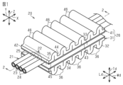
- FIG. 1 is a perspective view schematically showing the wire harness of the first embodiment.
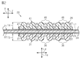
- FIG. FIG. 2 is a vertical cross-sectional view schematically showing the wire harness of the first embodiment.
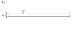
- FIG. 3 is an explanatory diagram for explaining the manufacturing process of the protective tape member in the first embodiment.
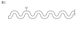
- FIG. 4 is an explanatory diagram for explaining the manufacturing process of the protective tape member in the first embodiment.
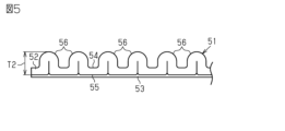
- FIG. 5 is a side view schematically showing the protective tape member of the first embodiment.
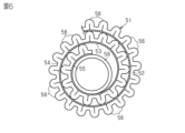
- FIG. 6 is a schematic diagram showing a state in which the protective tape member of the first embodiment is wound around a paper tube.
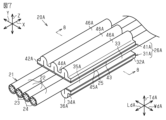
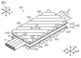
- FIG. 7 is a perspective view schematically showing the wire harness of the second embodiment.
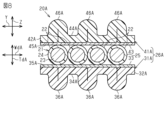
- FIG. 8 is a cross-sectional view schematically showing the wire harness of the second embodiment.
- FIG. 1 is a perspective view schematically showing the wire harness of the first embodiment.
- FIG. 2 is a vertical cross-sectional view schematically showing the wire harness of the first embodiment.
- FIG. 3 is an explanatory diagram
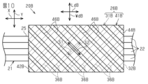
- FIG. 9 is a perspective view schematically showing the wire harness of the third embodiment.
- FIG. 10 is a plan view schematically showing the wire harness of the third embodiment.
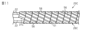
- FIG. 11 is a schematic diagram of a wire harness in a modified example.
- 12 is an end view schematically showing the wire harness in the modification shown in FIG. 11.
- FIG. 13 is a schematic diagram of a wire harness in a modification.
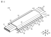
- FIG. 14 is a perspective view schematically showing a wire harness in a modified example.
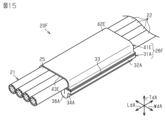
- FIG. 15 is a perspective view schematically showing a wire harness in a modified example.
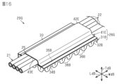
- FIG. 16 is a perspective view schematically showing a wire harness in a modified example.
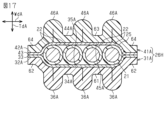
- 17 and 14 are cross-sectional views schematically showing wire harnesses in a modification.
- FIG. 18 is a side view schematically showing a protective tape member in a modified example.
- the protective tape member of the present disclosure includes: [1] A protective tape member that protects a wiring harness having at least one electric wire from foreign matter coming into contact with the electric wire, and has a belt-like first surface and a second surface opposite to the first surface. It has a substrate and an adhesive layer laminated on the second surface, the length direction of the substrate is a direction orthogonal to the width direction of the substrate, and the substrate is the second surface. A protective tape member having a plurality of protrusions extending continuously along the width direction of the base material on one surface, the plurality of protrusions being arranged in the length direction of the base material.
- the protective tape member can be adhered to the outer peripheral surface of the electric wire by bringing at least part of the adhesive layer into close contact with the outer peripheral surface of the electric wire.
- an exterior member for protecting the electric wire can be formed from the protective tape member.
- the plurality of protrusions can easily increase the maximum thickness of the protective tape member and easily increase the strength of the protective tape member. Therefore, by forming the exterior member from the protective tape member, compared with the case of forming the exterior member from the conventional tape member that does not have the convex portion, it is easy to form the exterior member with the same thickness and strength as the corrugated tube. can be formed to
- Both end regions in the length direction of the base material may have adhesive portions in which both end regions of the base material in the length direction of the base material are adhered to the outer peripheral surface of the electric wire by the adhesive layer. preferable.
- the protective tape member of the present disclosure includes: [3] A protective tape member that protects a wiring harness having at least one electric wire from foreign objects coming into contact with the electric wire, and has a belt-like first surface and a second surface opposite to the first surface. It has a substrate and an adhesive layer laminated on the second surface, the length direction of the substrate is a direction orthogonal to the width direction of the substrate, and the substrate is the second surface. A protective tape member having a plurality of protrusions extending continuously along the length direction of the base material on one surface, the plurality of protrusions being arranged in the width direction of the base material.
- the two tape members constituting the exterior member can be easily attached to each other.
- the two tape members can easily surround at least a part of the wire in the length direction of the wire over the entire circumference.
- the protective tape member of the present disclosure includes: [5] A protective tape member that protects a wiring harness having at least one electric wire from foreign matter coming into contact with the electric wire, and has a belt-like first surface and a second surface opposite to the first surface. It has a substrate and an adhesive layer laminated on the second surface, the length direction of the substrate is a direction orthogonal to the width direction of the substrate, and the substrate is the second surface.
- One surface has a plurality of protrusions extending continuously along a reference direction that intersects the width direction of the base material and the length direction of the base material when viewed from the thickness direction of the base material. , the plurality of protrusions are protective tape members arranged in the longitudinal direction of the base material.
- the wire harness of the present disclosure includes: [6] A wire harness comprising a wire bundle having a plurality of wires, wherein the wire bundle has a flat portion in which the plurality of wires are arranged flat in at least a portion in the direction in which the wire bundle extends;
- the exterior member has a first tape member and a second tape member that sandwich the flat portion from both sides in the thickness direction of the flat portion, and the first tape member includes the
- the protective tape member is the protective tape member adhered to the flat portion by the adhesive layer
- the second tape member is the protective tape member adhered to the flat portion by the adhesive layer. Harness.
- each of the first tape member and the second tape member can be attached to the flat portion by the adhesive layer, each of the first tape member and the second tape member can be easily arranged on the flat portion. That is, the exterior member can be easily attached to the electric wire.
- the wire harness of the present disclosure includes: [7] A wire harness comprising a wire bundle having a plurality of wires, wherein the wire bundle has a flat portion in which the plurality of wires are arranged flat in at least a portion in the direction in which the wire bundle extends, and the flat portion
- the exterior member has a first tape member and a second tape member that sandwich the flat portion from both sides in the thickness direction of the flat portion, and the first tape member includes the
- the protective tape member is the protective tape member adhered to the flat portion by the adhesive layer
- the second tape member is the protective tape member adhered to the flat portion by the adhesive layer. Harness.
- the wire harness of the present disclosure includes: [8] A wire harness comprising a wire bundle having a plurality of wires, wherein the wire bundle has a flat portion in which the plurality of wires are arranged flat in at least a portion in the direction in which the wire bundle extends, and the flat portion
- the exterior member has a first tape member and a second tape member that sandwich the flat portion from both sides in the thickness direction of the flat portion, and the first tape member and the second tape member are provided.
- Each of the two tape members is a wire harness which is the protective tape member adhered to the flat portion by the adhesive layer.
- the wire harness of the present disclosure includes: [9] A wire harness comprising a wire bundle having a plurality of wires, wherein the wire bundle has a flat portion in which the plurality of wires are arranged flat in at least a portion in the direction in which the wire bundle extends; a first tape member and a second tape member that are attached to each other with the flat portion sandwiched from both sides in the thickness direction of the flat portion; and the first tape
- the member is the protective tape member adhered to the flat portion by the adhesive layer, the base material possessed by the first tape member is the first base material, and the adhesive possessed by the first tape member is When the adhesive layer is the first pressure-sensitive adhesive layer, the second tape member is laminated on one side of the second base material which has a belt shape and is thinner than the first base material, and the second base material. It is a wire harness which has a 2nd adhesive layer.
- the first tape member is placed on the side of the flat portion in the thickness direction that may come into contact with a foreign object.
- the flat portion can be protected by the first tape member.
- the wire harness of the present disclosure includes: [10] At least one electric wire and an exterior member formed of the protective tape member, wherein the protective tape member overlaps a part of the protective tape member in the width direction, It is a wire harness that is spirally wound around the outer circumference of an electric wire.
- the adhesive layer of the protective tape member wound later causes a part in the width direction of the protective tape member wound earlier and a part in the width direction of the protective tape member wound later. is glued. Therefore, the helically wound protective tape member forms a cylindrical body surrounding the outer circumference of the electric wire. Then, the wire can be protected from foreign matter coming into contact with the wire harness by the cylindrical body formed of the protective tape member. In this way, by spirally winding the protective tape member around the outer periphery of the electric wire, it is possible to easily form an exterior member having the same thickness and strength as the corrugated tube.
- the protective tape member can be attached to the outer peripheral surface of the electric wire by the adhesive layer, there is no need to perform a step of fixing the exterior member formed of the protective tape member to the electric wire with a separate fixing tape member or the like. you can Therefore, the process of fixing the corrugated tube to the electric wire with the tape member and the process of winding the tape member around the outer periphery of the corrugated tube, which are performed when the corrugated tube is used as the exterior member, need not be performed. That is, the number of work steps can be reduced as compared with the case where the corrugated tube is used as the exterior member. Therefore, the exterior member can be easily attached to the electric wire.
- the exterior member is formed of the protective tape member, and each of the plurality of protrusions extends along the length direction of the electric wire on the outer periphery of the electric wire.
- a first embodiment of a protective tape member and a wire harness will be described below.
- a wire harness 20 shown in FIG. 1 is mounted in a vehicle such as an automobile, for example.
- the wire harness 20 includes, for example, a wire bundle 21 .
- the wire bundle 21 has a plurality of wires 22 .
- the wire bundle 21 has four wires 22 .
- the four electric wires 22 are, for example, of the same type and have the same diameter.
- the wire bundle 21 is a bundle of a plurality of wires 22 .
- each electric wire 22 has a conductive core wire 23 and an insulating coating 24 surrounding the core wire 23 and having insulating properties.
- 2 is a cross-sectional view taken along line 2-2 in FIG.
- Examples of the core wire 23 include a stranded wire formed by twisting a plurality of metal wires, a columnar conductor formed of a single columnar metal rod having a solid structure inside, a cylindrical conductor having a hollow structure inside, and the like. can be used. Moreover, as the core wire 23, for example, a combination of at least two of a stranded wire, a columnar conductor, and a cylindrical conductor may be used. As a material of the core wire 23, for example, a metal material such as a copper-based material or an aluminum-based material can be used.
- the insulating coating 24 covers, for example, the outer circumference of the core wire 23 over the entire circumferential direction around the center line L1 of the electric wire 22 .
- the insulating coating 24 is made of, for example, an insulating resin material.
- the center line L1 is illustrated by a one-dot chain line only in FIG.
- a center line L1 is a line passing through the center of the cross section of the electric wire 22 .
- the length direction of the electric wire 22 is the direction along the center line L1.
- a connector (not shown) is provided at the end of each electric wire 22 .
- the connector has a connector housing and connection terminals held inside the connector housing.
- the plurality of electric wires 22 are electrically connected to different connection terminals.
- the electric wire bundle 21 has a flat portion 25 in which a plurality of electric wires 22 are arranged flat in at least a portion in the extending direction of the electric wire bundle 21 .
- the wire bundle 21 has a flat portion 25 in a portion of the wire bundle 21 .
- the four electric wires 22 are arranged in a line along one direction that perpendicularly intersects the direction in which the electric wire bundle 21 extends.
- the direction in which the wire bundle 21 extends is hereinafter referred to as an extension direction X.
- the extending direction X is the length direction of the wire bundle 21 and is the direction along the center line L1 of the plurality of bundled wires 22 . That is, the extending direction X is a direction along the length direction of each electric wire 22 .
- the extension direction X is indicated by a double arrow.
- a plurality of electric wires 22 are arranged along the first direction Y perpendicularly crossing the extending direction X.
- a direction that perpendicularly intersects the extension direction X and the first direction Y is defined as a second direction Z.
- the first direction Y corresponds to the width direction of the flat portion 25 .
- the second direction Z corresponds to the thickness direction of the flat portion 25 .
- the cross-sectional shape of the flat portion 25 is a flat shape that is long in the first direction Y and thin in the second direction Z.
- the "cross section" is a cross section cut along a plane perpendicular to the extension direction X.
- the width of the flat portion 25 in the first direction Y is wider than the width of the flat portion 25 in the second direction Z.
- the four electric wires 22 extend parallel to each other, for example.
- the electric wires 22 adjacent to each other in the first direction Y are in contact with each other, for example.
- a plurality of electric wires are arranged flat means that a plurality of electric wires are arranged so that the cross-sectional shape of the electric wire bundle is flat. That is, the electric wires are arranged such that the cross-sectional shape of the electric wire bundle is long in a first direction perpendicular to the extending direction of the electric wire bundle and thin in a second direction perpendicular to the first direction. means lined up.
- the width of the flat portion in the first direction corresponds to the width of the widest portion in the cross section of the flat portion.
- the width of the flat portion in the first direction and the width of the flat portion in the second direction are different values, and the width of the flat portion in the first direction is greater than the width of the flat portion in the second direction. wider than the width of the part.
- the term “flat” means a state in which a plurality of electric wires are arranged in a flat manner.
- the wire harness 20 has an exterior member 26 that protects the flat portion 25 .
- the exterior member 26 has a first tape member 31 and a second tape member 41 that sandwich the flat portion 25 from both sides in the thickness direction of the flat portion 25 .
- the electric wire 22 in the flat portion 25 is integrally held by, for example, the first tape member 31 and the second tape member 41 .
- the electric wires 22 in the flat portion 25 may be collectively bundled by a tape member other than the first tape member 31 and the second tape member 41 .
- the first tape member 31 is a protective tape member that protects the electric wire 22 from foreign matter coming into contact with the wire harness 20 .
- the first tape member 31 has a first base material 32 and a first adhesive layer 33 laminated on one side of the first base material 32 .
- the first base material 32 has a strip shape.
- the length direction Ld of the first base material 32 is a direction orthogonal to the width direction Wd of the first base material 32 .
- the first base material 32 has a constant width, for example, along the length direction Ld.
- the first substrate 32 has a first side 34 and a second side 35 opposite the first side 34 .
- the first surface 34 is one surface of both surfaces of the first base material 32 in the thickness direction Td of the first base material 32 .
- the second surface 35 is the other surface of both surfaces of the first base material 32 in the thickness direction Td.
- the first base material 32 has a plurality of protrusions 36 continuously extending along the width direction Wd on the first surface 34 .
- Each projection 36 protrudes in the direction opposite to the second surface 35 .
- Each convex portion 36 has, for example, a shape in which the first base material 32 is folded in a mountain fold so as to swell toward the first surface 34 side.
- the multiple protrusions 36 are arranged in the length direction Ld.
- the plurality of protrusions 36 are arranged at regular intervals in the length direction Ld.
- Resin materials such as PVC (polyvinyl chloride), PP (polypropylene), and PET (polyethylene terephthalate) can be used as the material of the first base material 32, for example.
- the first adhesive layer 33 is laminated on the second surface 35 .
- the first adhesive layer 33 is laminated, for example, over the entire second surface 35 in the width direction Wd.
- the first pressure-sensitive adhesive layer 33 is laminated, for example, over at least the entire planar portion of the second surface 35 perpendicular to the projecting direction of the projections 36 .
- the first tape member 31 is attached to the flat portion 25 with the first adhesive layer 33 .
- the first tape member 31 is arranged on one side of the flat portion 25 in the thickness direction thereof. Further, the first tape member 31 is arranged, for example, so that the length direction Ld of the first base material 32 is along the extending direction X, that is, the length direction of the electric wire 22 . Therefore, each projection 36 extends along a direction perpendicular to the length direction of the electric wire 22 when viewed from the thickness direction Td of the first base material 32 .
- the first tape member 31 sticks to at least part of the outer peripheral surface of at least one of the wires 22 positioned between the first tape member 31 and the second tape member 41 . For example, the first tape member 31 sticks to a portion of each electric wire 22 in the flat portion 25 .
- the first tape member 31 has both end regions in the length direction Ld, and both end regions of the first base material 32 in the length direction Ld are adhered to the outer peripheral surface of the wire 22 by the first adhesive layer 33. 37. Since the first tape member 31 has the first bonding portions 37 , both ends of the first tape member 31 in the length direction Ld are bonded to the outer peripheral surface of the electric wire 22 .
- the second tape member 41 is, for example, like the first tape member 31, a protective tape member that protects the wires 22 from foreign matter coming into contact with the wire harness 20.
- the second tape member 41 has a belt-like second base material 42 having a first surface 44 and a second surface 45 opposite to the first surface 44 , and a second adhesive laminated on the second surface 45 . and layer 43 .
- the second base material 42 has a plurality of protrusions 46 continuously extending along the width direction of the second base material 42 on the first surface 44 .
- the second tape member 41 is of the same type as the first tape member 31, for example.
- the second base material 42 and the second adhesive layer 43 are the same as the first base material 32 and the first adhesive layer. It has the same configuration as the agent layer 33 .
- the convex portion 46 has the same configuration as the convex portion 36 . Therefore, detailed description of the second tape member 41 is omitted.
- the second tape member 41 is attached to the flat portion 25 with the second adhesive layer 43 .
- the second tape member 41 is arranged on the other side of the flat portion 25 in the thickness direction. Further, the second tape member 41 is arranged, for example, so that the length direction of the second base material 42 is along the extension direction X, that is, the length direction of the electric wire 22 . Therefore, each projection 46 extends along a direction perpendicular to the length direction of the wire 22 when viewed from the thickness direction of the second base material 42 .
- the second tape member 41 sticks to at least part of the outer peripheral surface of at least one of the wires 22 positioned between the first tape member 31 and the second tape member 41 . For example, the second tape member 41 sticks to a portion of each electric wire 22 in the flat portion 25 .
- the second tape member 41 is adhered to both end regions of the second base material 42 in the length direction, and both end regions of the second base material 42 in the same length direction are adhered to the outer peripheral surface of the electric wire 22 by the second adhesive layer 43 .
- FIG. 3 is a side view of the strip 52 viewed from the width direction of the strip 52.
- the strip 52 is to become the first base material 32 or the second base material 42 .
- strip 52 has the same width as first substrate 32 .
- a first forming step is performed in which the strip 52 is formed using a mold.
- the strip 52 is formed by a mold so as to have a wavy shape when viewed from the width direction of the strip 52, for example.
- FIG. 4 is a side view of the strip 52 after completion of the first forming step, viewed from the width direction of the strip 52. As shown in FIG.
- a second forming process is performed to form a plurality of projections 56 by compressing the band material 52 that has been formed into a wave shape in the first forming process in the longitudinal direction.
- a mold is used to form a plurality of protrusions 56 on the strip 52 along the longitudinal direction of the strip 52 .
- a second surface 55 of the strip 52 opposite to the first surface 54 from which the protrusions 56 protrude is formed flat.
- FIG. 5 is a side view of the protective tape member 51 viewed from the width direction of the band material 52.
- the protective tape member 51 can be transported in a state of being spirally wound around the outer circumference of the paper tube 58, for example.
- the first tape member 31 and the second tape member 41 can be formed.
- the thickness T1 of the strip 52 prepared for forming the protective tape member 51, the maximum thickness T2 of the strip 52 in the protective tape member 51 etc. may be set to desired values according to the wear strength and rigidity required for the exterior member 26 .
- the maximum thickness T2 of the strip 52 in the protective tape member 51 that is, the base material of the protective tape member 51, is the maximum thickness T3 of the first base material 32 in the first tape member 31 and the second It is the same as each of the maximum thicknesses T4 of the second base material 42 in the tape member 41 .
- the first tape member 31 and the second tape member 41 are protective tape members that protect the wire 22 from foreign matter coming into contact with the wire harness 20 having at least one wire 22 .
- the first tape member 31 includes a strip-shaped first base material 32 having a first surface 34 and a second surface 35 opposite to the first surface 34, and a first adhesive laminated on the second surface 35. and layer 33 .
- the length direction Ld of the first base material 32 is a direction orthogonal to the width direction Wd of the first base material 32 .
- the first base material 32 has a plurality of protrusions 36 continuously extending along the width direction Wd on the first surface 34 .
- the plurality of protrusions 36 are arranged in the length direction Ld of the first base material 32 .
- the second tape member 41 has a belt-like second base material 42 having a first surface 44 and a second surface 45 opposite to the first surface 44 , and a second adhesive laminated on the second surface 45 . and layer 43 .
- the length direction of the second base material 42 is a direction orthogonal to the width direction of the second base material 42 .
- the second base material 42 has a plurality of protrusions 46 continuously extending along the width direction of the second base material 42 on the first surface 44 .
- the plurality of protrusions 46 are arranged in the length direction of the second base material 42 .
- the first tape member 31 can be attached to the outer peripheral surface of the electric wire 22 by bringing at least part of the first adhesive layer 33 into close contact with the outer peripheral surface of the electric wire 22 .
- the second tape member 41 can be attached to the outer peripheral surface of the electric wire 22 .
- the exterior member 26 for protecting the electric wire 22 can be formed from the first and second tape members 31 and 41 .
- the maximum thickness of the first tape member 31 can be easily increased by the plurality of protrusions 36, and the strength of the first tape member 31 can be easily increased.
- the plurality of protrusions 46 can easily increase the maximum thickness of the second tape member 41 and easily increase the strength of the second tape member 41 . Therefore, by forming the exterior member 26 with the first and second tape members 31 and 41, the thickness equivalent to that of the corrugated tube can be obtained compared to the case where the exterior member is formed with a conventional tape member having no protrusions. And the strong exterior member 26 can be easily formed.
- the first tape member 31 has both end regions in the length direction Ld, and both end regions of the first base material 32 in the length direction Ld are adhered to the outer peripheral surface of the wire 22 by the first adhesive layer 33. It has a first adhesive part 37 that The second tape member 41 is adhered to both end regions of the second base material 42 in the length direction, and both end regions of the second base material 42 in the same length direction are adhered to the outer peripheral surface of the electric wire 22 by the second adhesive layer 43 . It has a second adhesive part 47 that
- the wire harness 20 includes a wire bundle 21 having a plurality of wires 22 .
- the wire bundle 21 has a flat portion 25 in which the plurality of wires 22 are arranged flat on at least a portion of the wire bundle 21 in the direction in which the wire bundle 21 extends.
- the wire harness 20 includes an exterior member 26 that protects the flat portion 25 .
- the exterior member 26 has a first tape member 31 and a second tape member 41 that sandwich the flat portion 25 from both sides in the thickness direction of the flat portion 25 .
- the first tape member 31 is a protective tape member adhered to the flat portion 25 with the first adhesive layer 33 .
- the second tape member 41 is a protective tape member adhered to the flat portion 25 with the second adhesive layer 43 .
- the first tape member 31 and the second tape member 41 can be attached to the flat portion 25 by the first adhesive layer 33 and the second adhesive layer 43, respectively. Therefore, each of the first tape member 31 and the second tape member 41 can be easily arranged with respect to the flat portion 25 . That is, the exterior member 26 can be easily attached to the electric wire 22 .
- the thickness of the exterior member formed by the conventional tape member is set to a thickness equivalent to the maximum thickness of the first tape member 31 or the second tape member 41. It is conceivable to wind the conventional tape member around the outer circumference of the electric wire so as to obtain However, in this case, the exterior member formed of the conventional tape member has a larger mass than the exterior member 26 formed of the first tape member 31 and the second tape member 41 .
- the exterior member 26 formed by the first tape member 31 and the second tape member 41 can have a smaller mass and the same strength as the exterior member formed by the conventional tape member. Therefore, the manufacturing cost of the exterior member 26 can be reduced as compared with the case where the exterior member is formed from a conventional tape member.
- the exterior member is thinner than the exterior member 26 . That is, the exterior member 26 formed by the first tape member 31 and the second tape member 41 is an exterior member formed by arranging conventional tape members in the same manner as the first tape member 31 and the second tape member 41. thicker than that. Therefore, the wear resistance of the exterior member 26 can be improved as compared with the exterior member.
- the first tape member 31 and the second tape member 41 are protective tape members having the same configuration. Therefore, if one type of protective tape member 51 is prepared, both the first tape member 31 and the second tape member 41 can be prepared. Therefore, compared to the case where the first tape member 31 and the second tape member 41 are protective tape members having different configurations, it becomes easier to prepare the protective tape member that constitutes the exterior member 26 . In addition, since it is only necessary to manufacture one type of protective tape member, compared to the case of manufacturing two types of protective tape members for the first tape member 31 and the second tape member 41, the exterior member 26 Such manufacturing costs can be reduced.
- each projection 36 of the first tape member 31 and each projection 46 of the second tape member 41 are perpendicular to the length direction of the electric wire 22 when viewed from the thickness direction Td. It extends along the direction to make. Therefore, the portion of the electric wire 22 to which the exterior member 26 is attached can be easily bent in the thickness direction Td.
- the wire harness 20A of the second embodiment has an exterior member 26A for protecting the flat portion 25 instead of the exterior member 26 in the wire harness 20 of the first embodiment.
- FIG. 8 is a cross-sectional view taken along line 8-8 in FIG.
- the exterior member 26A has a first tape member 31A and a second tape member 41A that sandwich the flat portion 25 from both sides of the flat portion 25 in the thickness direction.
- the electric wire 22 in the flat portion 25 is integrally held by, for example, the first tape member 31A and the second tape member 41A.
- the first tape member 31A is a protective tape member that protects the electric wire 22 from foreign matter coming into contact with the wire harness 20A.
- 31 A of 1st tape members have 32 A of 1st base materials, and the 1st adhesive layer 33 laminated
- the first base material 32A has a strip shape.
- the length direction LdA of the first base material 32A is a direction orthogonal to the width direction WdA of the first base material 32A.
- the first base material 32A has a constant width, for example, along the length direction LdA.
- the first substrate 32A has a first surface 34A and a second surface 35A opposite the first surface 34A. Of both surfaces of the first substrate 32A in the thickness direction TdA of the first substrate 32A, one surface is the first surface 34A and the other surface is the second surface 35A.
- the first base material 32A has a plurality of protrusions 36A continuously extending along the length direction LdA on the first surface 34A.
- 32 A of 1st base materials have three convex parts 36A, for example.
- Each convex portion 36A protrudes in the direction opposite to the second surface 35A.
- Each convex portion 36A has, for example, a shape in which the first base material 32A is folded in a mountain fold so as to swell toward the first surface 34A.
- the plurality of convex portions 36A are arranged in the width direction WdA.
- the plurality of protrusions 36A are arranged at regular intervals in the width direction WdA.
- the material of the first base material 32A the same resin material as that of the first base material 32 of the first embodiment can be used.
- the first adhesive layer 33 is laminated on the second surface 35A.
- the first adhesive layer 33 is laminated, for example, over the entire second surface 35A in the width direction WdA.
- the first pressure-sensitive adhesive layer 33 is laminated, for example, over at least the entire planar portion of the second surface 35A that is perpendicular to the projecting direction of the projections 36A.
- the first tape member 31A is adhered to the flat portion 25 by the first adhesive layer 33.
- the first tape member 31A is arranged on one side of the flat portion 25 in the thickness direction thereof.
- the first tape member 31A is arranged, for example, such that the length direction LdA of the first base material 32A is along the extension direction X, that is, the length direction of the electric wire 22 . Therefore, each convex portion 36A extends along the length direction of the electric wire 22 when viewed from the thickness direction TdA.
- the first tape member 31A sticks to at least part of the outer peripheral surface of at least one of the wires 22 positioned between the first tape member 31A and the second tape member 41A. For example, the first tape member 31A sticks to a portion of each electric wire 22 on the flat portion 25 .
- the second tape member 41A is, for example, a protective tape member that protects the electric wires 22 from foreign matter coming into contact with the wire harness 20A, similar to the first tape member 31A.
- the second tape member 41A includes a strip-shaped second base material 42A having a first surface 44A and a second surface 45A opposite to the first surface 44A, and a second adhesive laminated on the second surface 45A. and layer 43 .
- the second base material 42A has a plurality of protrusions 46A extending continuously along the length direction of the second base material 42A on the first surface 44A.
- the second tape member 41A is, for example, of the same type as the first tape member 31A.
- the second base material 42A and the second adhesive layer 43 are the same as the first base material 32A and the first adhesive layer. It has the same configuration as the agent layer 33 .
- the convex portion 46A has the same configuration as the convex portion 36A.
- the second tape member 41A is adhered to the flat portion 25 by the second adhesive layer 43.
- the second tape member 41A is arranged on the other side of the flat portion 25 in the thickness direction. Further, the second tape member 41A is arranged, for example, so that the length direction of the second base material 42A is along the extension direction X, that is, the length direction of the electric wire 22 . Therefore, each convex portion 46A extends along the length direction of the electric wire 22 when viewed from the thickness direction of the second base material 42A.
- the second tape member 41A sticks to at least part of the outer peripheral surface of at least one of the wires 22 positioned between the first tape member 31A and the second tape member 41A. For example, the second tape member 41A sticks to a portion of each electric wire 22 on the flat portion 25 .
- the first tape member 31A and the second tape member 41A are protective tape members that protect the wire 22 from foreign matter coming into contact with the wire harness 20A including at least one wire 22.
- the first tape member 31A includes a strip-shaped first base material 32A having a first surface 34A and a second surface 35A opposite to the first surface 34A, and a first adhesive laminated on the second surface 35A. and layer 33 .
- the length direction LdA of the first base material 32A is a direction orthogonal to the width direction WdA of the first base material 32A.
- 32 A of 1st base materials have several convex part 36A continuously extended along the length direction LdA on 34 A of 1st surfaces.
- the second tape member 41A includes a strip-shaped second base material 42A having a first surface 44A and a second surface 45A opposite to the first surface 44A, and a second adhesive laminated on the second surface 45A. and layer 43 .
- the length direction of the second base material 42A is a direction perpendicular to the width direction of the second base material 42A.
- the second base material 42A has a plurality of protrusions 46A extending continuously along the length direction of the second base material 42A on the first surface 44A. 46 A of several convex parts are located in a line with the width direction of 42 A of 2nd base materials.
- the first tape member 31A can be attached to the outer peripheral surface of the electric wire 22 by bringing at least part of the first adhesive layer 33 into close contact with the outer peripheral surface of the electric wire 22.
- the second tape member 41A can be adhered to the outer peripheral surface of the electric wire 22 by attaching at least part of the second adhesive layer 43 to the outer peripheral surface of the electric wire 22 .
- the exterior member 26A for protecting the electric wire 22 can be formed from the first and second tape members 31A and 41A.
- the maximum thickness of the first tape member 31A can be easily increased by the plurality of protrusions 36A, and the strength of the first tape member 31A can be easily increased.
- the plurality of protrusions 46A can easily increase the maximum thickness of the second tape member 41A and easily increase the strength of the second tape member 41A. Therefore, by forming the exterior member 26A from the first and second tape members 31A and 41A, the thickness equivalent to that of the corrugated tube can be achieved compared to the case where the exterior member is formed from a conventional tape member having no protrusions. And the strong exterior member 26A can be easily formed.
- the wire harness 20A includes a wire bundle 21 having a plurality of wires 22.
- the wire bundle 21 has a flat portion 25 in which the plurality of wires 22 are arranged flat on at least a portion of the wire bundle 21 in the direction in which the wire bundle 21 extends.
- the wire harness 20A includes an exterior member 26A that protects the flat portion 25.
- the exterior member 26A has a first tape member 31A and a second tape member 41A that sandwich the flat portion 25 from both sides of the flat portion 25 in the thickness direction.
- the first tape member 31A is a protective tape member adhered to the flat portion 25 by the first adhesive layer 33 .
- the second tape member 41A is a protective tape member adhered to the flat portion 25 by the second adhesive layer 43 .
- each of the first tape member 31A and the second tape member 41A is a protective tape member whose maximum thickness is increased by the plurality of protrusions 36A or the plurality of protrusions 46A and whose strength is enhanced. be. Therefore, the exterior member 26A formed by the first tape member 31A and the second tape member 41A has the same thickness and strength as the corrugated tube, compared to the exterior member formed by the conventional tape member having no projections. can be easily provided. Also, the first tape member 31A and the second tape member 41A can be attached to the flat portion 25 by the first adhesive layer 33 and the second adhesive layer 43, respectively. Therefore, each of the first tape member 31A and the second tape member 41A can be easily arranged with respect to the flat portion 25 . That is, the exterior member 26A can be easily attached to the electric wire 22. As shown in FIG.
- each convex portion 36A of the first tape member 31A and each convex portion 46A of the second tape member 41A extend along the length direction of the electric wire 22. Therefore, it is possible to suppress bending of the electric wire 22 at the portion where the exterior member 26A is attached.
- a third embodiment of an exterior member and a wire harness will be described below.
- the same reference numerals are given to the same or corresponding structures as those of the first embodiment, and part or all of the description of the structures is omitted.
- the wire harness 20B of the third embodiment has an exterior member 26B for protecting the flat portion 25 instead of the exterior member 26 in the wire harness 20 of the first embodiment.
- 10 is a plan view of the wire harness 20B viewed from the thickness direction of the flat portion 25.
- the exterior member 26B has a first tape member 31B and a second tape member 41B that sandwich the flat portion 25 from both sides in the thickness direction of the flat portion 25 .
- the electric wire 22 in the flat portion 25 is integrally held by, for example, the first tape member 31B and the second tape member 41B.
- the first tape member 31B is a protective tape member that protects the electric wire 22 from foreign matter coming into contact with the wire harness 20B.
- the first tape member 31B has a first base material 32B and a first adhesive layer 33 laminated on one side of the first base material 32B.
- the first base material 32B has a strip shape.
- the length direction LdB of the first base material 32B is a direction orthogonal to the width direction WdB of the first base material 32A.
- the first base material 32B has a constant width, for example, along the length direction LdB.
- the first substrate 32B has a first surface 34B and a second surface 35B opposite the first surface 34B. Of both surfaces of the first substrate 32B in the thickness direction TdB of the first substrate 32A, one surface is the first surface 34B and the other surface is the second surface 35B.
- the first base material 32B has, on the first surface 34B, a plurality of protrusions 36B that continuously extend along a reference direction S1 that intersects the width direction WdB and the length direction LdB when viewed from the thickness direction TdB. have. Each projection 36B protrudes in the direction opposite to the second surface 35B.
- Each convex portion 36B has, for example, a shape in which the first base member 32B is folded in a mountain fold so as to swell toward the first surface 34B.
- the multiple protrusions 36B are arranged in the length direction LdB.
- the plurality of convex portions 36B are arranged at regular intervals in the length direction LdB.
- the material of the first base material 32B the same resin material as that of the first base material 32 of the first embodiment can be used.
- the first adhesive layer 33 is laminated on the second surface 35B.
- the first adhesive layer 33 is laminated, for example, over the entire second surface 35B in the width direction WdB.
- the first pressure-sensitive adhesive layer 33 is laminated, for example, over at least the entire planar portion of the second surface 35B perpendicular to the projecting direction of the projections 36B.
- the first tape member 31B is adhered to the flat portion 25 by the first adhesive layer 33.
- the first tape member 31B is arranged on one side of the flat portion 25 in the thickness direction thereof. Further, the first tape member 31B is arranged, for example, such that the length direction LdB of the first base material 32B is along the extension direction X, that is, the length direction of the electric wire 22. As shown in FIG. Therefore, each convex portion 36B extends along the direction intersecting the length direction of the electric wire 22 when viewed from the thickness direction TdB.
- the first tape member 31B sticks to at least part of the outer peripheral surface of at least one of the wires 22 positioned between the first tape member 31B and the second tape member 41B. For example, the first tape member 31B sticks to a portion of each electric wire 22 on the flat portion 25 .
- the second tape member 41B is, for example, a protective tape member that protects the electric wires 22 from foreign matter coming into contact with the wire harness 20B, similar to the first tape member 31B.
- the second tape member 41B has a belt-like second base material 42B having a first surface 44B and a second surface 45B opposite to the first surface 44B, and a second adhesive laminated on the second surface 45B. and layer 43 .
- the second base material 42B has a first surface 44B provided with a reference that intersects the width direction of the second base material 42B and the length direction of the second base material 42B when viewed from the thickness direction of the second base material 42B. It has a plurality of protrusions 46B that continuously extend along the direction S2.
- the second tape member 41B is, for example, of the same type as the first tape member 31B.
- the second base material 42B and the second adhesive layer 43 are the first base material 32B and the first adhesive layer 43. It has the same configuration as the agent layer 33 .
- the convex portion 46B has the same configuration as the convex portion 36B.
- the second tape member 41B is adhered to the flat portion 25 by the second adhesive layer 43.
- the second tape member 41B is arranged on the other side of the flat portion 25 in the thickness direction. Further, the second tape member 41B is arranged, for example, such that the length direction of the second base material 42A is along the extension direction X, that is, the length direction of the electric wire 22. As shown in FIG. Furthermore, in the second tape member 41B, when the wire harness 20B is viewed from the thickness direction TdB, the direction in which the protrusions 36B extend (ie, the reference direction S1) intersects with the direction in which the protrusions 46B extend (ie, the reference direction S2).
- each convex portion 46B extends along a direction intersecting the length direction of the electric wire 22 when viewed from the thickness direction TdB, and intersects the convex portion 36B.
- the second tape member 41B sticks to at least part of the outer peripheral surface of at least one of the wires 22 positioned between the first tape member 31B and the second tape member 41B.
- the second tape member 41B sticks to a portion of each electric wire 22 on the flat portion 25 .
- the first tape member 31B and the second tape member 41B are protective tape members that protect the wire 22 from foreign matter coming into contact with the wire harness 20B having at least one wire 22 .
- the first tape member 31B includes a strip-shaped first base material 32B having a first surface 34B and a second surface 35B opposite to the first surface 34B, and a first adhesive laminated on the second surface 35B. and layer 33 .
- the length direction LdB of the first base material 32B is a direction perpendicular to the width direction WdB of the first base material 32B.
- the first base material 32B has, on the first surface 34B, a plurality of protrusions 36B that continuously extend along a reference direction S1 that intersects the width direction WdB and the length direction LdB when viewed from the thickness direction TdB. have.
- the multiple protrusions 36B are arranged in the length direction LdB.
- the second tape member 41B has a belt-like second base material 42B having a first surface 44B and a second surface 45B opposite to the first surface 44B, and a second adhesive laminated on the second surface 45B. and layer 43 .
- the length direction of the second base material 42B is a direction perpendicular to the width direction of the second base material 42B.
- the second base material 42B has a first surface 44B provided with a reference that intersects the width direction of the second base material 42 when viewed from the thickness direction of the second base material 42 and intersects the length direction of the second base material 42. It has a plurality of protrusions 46B that continuously extend along the direction S2. A plurality of protrusions 46B are arranged in the length direction of the second base material 42B.
- the first tape member 31B can be attached to the outer peripheral surface of the electric wire 22 by bringing at least part of the first adhesive layer 33 into close contact with the outer peripheral surface of the electric wire 22 .
- the second tape member 41B can be adhered to the outer peripheral surface of the electric wire 22 by attaching at least part of the second adhesive layer 43 to the outer peripheral surface of the electric wire 22 .
- the exterior member 26B for protecting the electric wire 22 can be formed from the first and second tape members 31B and 41B.
- the maximum thickness of the first tape member 31B can be easily increased by the plurality of protrusions 36B, and the strength of the first tape member 31B can be easily increased.
- the plurality of protrusions 46B can easily increase the maximum thickness of the second tape member 41B and easily increase the strength of the second tape member 41B. Therefore, by forming the exterior member 26B from the first and second tape members 31B and 41B, the thickness equivalent to that of the corrugated tube can be achieved compared to the case where the exterior member is formed from a conventional tape member having no protrusions. And the strong exterior member 26B can be easily formed.
- the wire harness 20B includes a wire bundle 21 having a plurality of wires 22.
- the wire bundle 21 has a flat portion 25 in which the plurality of wires 22 are arranged flat on at least a portion of the wire bundle 21 in the direction in which the wire bundle 21 extends.
- the wire harness 20B includes an exterior member 26B that protects the flat portion 25.
- the exterior member 26B has a first tape member 31B and a second tape member 41B that sandwich the flat portion 25 from both sides of the flat portion 25 in the thickness direction.
- the first tape member 31B is a protective tape member adhered to the flat portion 25 with the first adhesive layer 33 .
- the second tape member 41B is a protective tape member adhered to the flat portion 25 with the second adhesive layer 43 .
- each of the first tape member 31B and the second tape member 41B is a protective tape member whose maximum thickness is increased by the plurality of protrusions 36B or the plurality of protrusions 46B and whose strength is enhanced. be. Therefore, the exterior member 26B formed by the first tape member 31B and the second tape member 41B has the same thickness and strength as the corrugated tube, compared to the exterior member formed by the conventional tape member having no projections. can be easily provided. Also, the first tape member 31B and the second tape member 41B can be attached to the flat portion 25 by the first adhesive layer 33 and the second adhesive layer 43, respectively. Therefore, each of the first tape member 31B and the second tape member 41B can be easily arranged with respect to the flat portion 25 . That is, the exterior member 26B can be easily attached to the electric wire 22. As shown in FIG.
- the second tape member 41B is arranged such that the plurality of protrusions 46B intersect with the plurality of protrusions 36B when viewed from the thickness direction TdB. For this reason, compared to the case where the second tape member 41B is arranged such that the extending direction of each convex portion 46B is along the extending direction of each convex portion 36B when viewed from the thickness direction TdB, the exterior member 26B is It is possible to suppress bending of the electric wire 22 in the mounted portion.
- Each embodiment can be modified and implemented as follows. Each embodiment and the following modifications can be implemented in combination with each other within a technically consistent range.
- symbol is attached
- the 1st tape member 31 does not need to have the 1st adhesion part 37.
- the second tape member 41 may not have the second adhesive portion 47 .
- the 2nd tape member 41B is arrange
- the second tape member 41B may be arranged such that the extending direction of each convex portion 46B is along the extending direction of each convex portion 36B when viewed from the thickness direction TdB. That is, the second tape member 41 may be arranged so that the reference direction S2 and the reference direction S1 are parallel.
- a wire harness 20C illustrated in FIGS. 11 and 12 includes at least one electric wire 22 and an exterior member 26C formed of the protective tape member 51 of the first embodiment. 12, the exterior member 26C is illustrated as an end view cut along the length direction of the electric wire 22.
- the wire harness 20C includes a plurality of electric wires 22, for example.
- the protective tape member 51 is spirally wound around the electric wire 22 so that the protective tape member 51 partially overlaps with the protective tape member 51 in the width direction.
- the protective tape member 51 may have an adhesive portion 37C similar to the first adhesive portion 37 of the first embodiment in the end region of the protective tape member 51 in the longitudinal direction.
- the adhesive layer 53 of the protective tape member 51 wound later causes a portion of the previously wound protective tape member 51 in the width direction and the width direction of the later wound protective tape member 51 to be separated from each other. is adhered to. Therefore, the spirally wound protective tape member 51 forms a cylindrical body surrounding the outer circumference of the electric wire 22 .
- the cylindrical body formed by the protective tape member 51 can protect the electric wire 22 from foreign matter coming into contact with the wire harness 20C.
- the protective tape member 51 can be attached to the outer peripheral surface of the electric wire 22 by the adhesive layer 53, the exterior member 26C formed by the protective tape member 51 can be attached to the electric wire 22 by a separate fixing tape member or the like. No fixing process is required. Therefore, the process of fixing the corrugated tube to the electric wire with the tape member and the process of winding the tape member around the outer periphery of the corrugated tube, which are performed when the corrugated tube is used as the exterior member, need not be performed. That is, the number of work steps can be reduced as compared with the case where the corrugated tube is used as the exterior member. Therefore, the exterior member 26C can be easily attached to the electric wire 22. As shown in FIG.
- the protective tape member used as the first tape member 31B or the second tape member 41B in the third embodiment may be spirally wound around the outer circumference of the electric wire 22 as the exterior member 26C. Even in this way, the same effect as in the example shown in FIG. 11 can be obtained.
- a wire harness 20D illustrated in FIG. 13 includes at least one electric wire 22 and an exterior member 26D formed of the first tape member 31B (protective tape member) of the third embodiment.
- the first tape member 31B is spirally wound around the outer periphery of the electric wire 22 so that a portion of the first tape member 31B in the width direction overlaps.
- each of the plurality of protrusions 36 ⁇ /b>B extends along the length direction of the electric wire 22 on the outer periphery of the electric wire 22 , for example.
- each projection 36B with respect to the length direction LdB and the width direction WdB of the first base material 32B is such that when the first tape member 31B is helically wound around the wire 22, each projection 36B The angle is set so that the electric wire 22 can extend along the length direction.
- the reference direction S1 is set along the length direction of the wire 22 when the first tape member 31B is spirally wound around the wire 22 .
- either one of the first tape member 31 and the second tape member 41 may be replaced with a general existing tape member used for bundling the electric wires 22 . You may change similarly in the said 2nd Embodiment and said 3rd Embodiment.
- a wire harness 20E illustrated in FIG. 14 includes an exterior member 26E that protects the flat portion 25.
- the exterior member 26 ⁇ /b>E has a first tape member 31 and a second tape member 41 ⁇ /b>E that are attached to each other with the flat portion 25 interposed from both sides in the thickness direction of the flat portion 25 .
- the first tape member 31 is that of the first embodiment.
- the second tape member 41E has a strip-shaped second base material 42E thinner than the first base material 32, and a second adhesive layer 43E laminated on one side of the second base material 42E.
- the second tape member 41E is an existing tape member generally used for bundling the electric wires 22 .
- a commercially available PVC tape can be used as the second tape member 41E.
- the second base material 42 ⁇ /b>E does not have protrusions such as the protrusions 36 . Furthermore, the second base material 42E has, for example, a uniform thickness.
- the second tape member 41E is adhered to the flat portion 25 by the second adhesive layer 43E.
- the first tape member 31 and the second tape member 41E may be directly attached to each other on both sides of the flat portion 25 in the width direction, for example.
- the side of the flat portion 25 in the thickness direction that may come into contact with a foreign object can be removed.
- the flat portion 25 can be protected by the first tape member 31 by arranging the first tape member 31 on the .
- the manufacturing cost of the exterior member 26E can be further reduced.
- a wire harness 20F illustrated in FIG. 15 includes an exterior member 26F that protects the flat portion 25.
- the exterior member 26 ⁇ /b>F has a first tape member 31 ⁇ /b>A and a second tape member 41 ⁇ /b>E that are attached to each other with the flat portion 25 interposed from both sides in the thickness direction of the flat portion 25 .
- the first tape member 31A is that of the second embodiment.
- the first tape member 31A and the second tape member 41E may be directly bonded to each other on both sides of the flat portion 25 in the width direction, for example. Even in this way, the same effects as in the example shown in FIG. 14 can be obtained.
- a wire harness 20G illustrated in FIG. 16 includes an exterior member 26G that protects the flat portion 25.
- the exterior member 26 ⁇ /b>F has a first tape member 31 ⁇ /b>B and a second tape member 41 ⁇ /b>E that are attached to each other with the flat portion 25 interposed from both sides in the thickness direction of the flat portion 25 .
- the first tape member 31B is that of the third embodiment.
- the first tape member 31B and the second tape member 41E may be directly attached to each other on both sides of the flat portion 25 in the width direction, for example. Even in this way, the same effects as in the example shown in FIG. 14 can be obtained.
- region in the width direction WdA may be directly bonded together mutually.
- the exterior member 26H is composed of two tape members, that is, a first tape member 31A and a second tape member 31A and a second tape member 31A and a second tape member 31A. It may be formed by the tape member 41A.
- the first tape member 31A has an accommodating portion 61 and an end adhered portion 62.
- the accommodation portion 61 is a portion of the first tape member 31A that is recessed in the direction from the second surface 35A toward the first surface 34A and extends in the length direction LdA.
- the accommodation portion 61 is positioned at the central portion of the first tape member 31A in the width direction WdA.
- a portion of the electric wire 22 in the length direction is arranged inside the accommodation portion 61 .
- the end adhered portions 62 are positioned on both sides of the accommodating portion 61 in the width direction WdA of the first tape member 31A.
- the end sticking portion 62 is stuck to the second tape member 41A on the other side by the first adhesive layer 33 .
- the first tape member 31A has, for example, end adhered portions 62 in both end regions of the first tape member 31A in the width direction WdA.
- the second tape member 41A has, for example, the same shape as the first tape member 31A. That is, the second tape member 41 has an accommodating portion 63 having the same shape as the accommodating portion 61 and an end adhered portion 64 having the same shape as the end adhered portion 62 .
- the end adhering portions 64 are positioned on both sides of the accommodating portion 63 in the width direction WdA and are adhered to the first tape member 31A on the other side by the second adhesive layer 43 .
- the first tape member 31A and the second tape member 41A are bonded together at the ends 62 and 64 so that the wires 22 are housed inside the housing portions 61 and 63 of each other. so that they are glued together.
- the accommodation portion 61 and the accommodation portion 63 form a cylindrical body through which the electric wires 22 pass.
- the second tape member 41A can be attached to the end attachment portion 62 of the first tape member 31A.
- the first tape member 31A can be attached to the end attachment portion 64 of the second tape member 41A. Therefore, it becomes easier to bond the first tape member 31A and the second tape member 41A that constitute the exterior member 26H.
- at least part of the wire 22 in the length direction of the wire 22 can be easily surrounded over the entire circumference by the first tape member 31A and the second tape member 41A.
- the exterior member 26H can also be attached to portions other than the flat portion 25 of the wire bundle 21, i.e., portions where the wires 22 are not bundled in a flat shape. Wearable.
- the second tape member 41A is replaced with the second tape member 41A of the second embodiment that does not include the second tape member 41, the accommodating portion 63, and the end sticking portion 64 of the first embodiment. , and the second tape member 41B of the third embodiment.
- first tape member 31 of the first embodiment may have the accommodating portion 61 and the end adhering portion 62 .
- the second tape member 41 of the first embodiment may have the accommodating portion 63 and the end adhering portion 64 .
- the first tape member 31B and the second tape member 41B of the third embodiment may be similarly changed.
- the wire harness 20F exemplified in FIG. 15 may be provided with the first tape member 31A having the accommodating portion 61 and the end adhering portion 62 exemplified in FIG. 17 instead of the first tape member 31A.
- a protective tape member 71 shown in FIG. 18 has a base material 72 .
- An adhesive layer 73 is laminated on the second surface 75 of the base material 72 .
- the base material 72 has a plurality of protrusions 76 extending in the width direction of the base material 72 on the first surface 74 .
- the base material 72 is formed by processing a belt material 52A having a uniform thickness.
- the outer shape of the strip 52A is indicated by a chain double-dashed line.
- a base material 72 having a plurality of protrusions 76 is formed by partially scraping off the band material 52A.
- the chain double-dashed line shown in FIG. 18 represents the outer shape of the strip 52A before being partially scraped off.
- the convex portion 76 has a rectangular cross section perpendicular to the direction in which the convex portion 76 extends.
- the cross-sectional shape of the convex portion 76 may be polygonal, semicircular, or any other shape other than square. If the corners of the tip of the protrusion 76 are rounded, the protrusion 76 is less likely to crack than when the corner of the tip of the protrusion 76 is sharp.
- the breakage resistance of the protrusions 76 near the proximal ends can be improved.
- the base material 72 having the protrusions 76 may be formed by injection molding or the like.
- the exterior member 26A of the second embodiment and the exterior member 26B of the third embodiment may be similarly changed. That is, any first tape member among the first tape members 31, 31A, and 31B and any second tape member among the second tape members 41, 41A, and 41B may be combined to form the exterior member. .
- the first tape member 31 of the first embodiment further includes protrusions extending in the length direction Ld, and for both the width direction Wd and the length direction Ld. It may have a convex portion extending in a direction in which it is inclined.
- the second tape member 41 may be similarly changed. Also, the second embodiment and the third embodiment may be similarly modified.
- each of the convex portions 36 and 46 may be slightly curved as long as it extends along the width direction Wd.
- each of the convex portions 36A, 46A may be slightly curved as long as it extends along the length direction LdA.
- each of the convex portions 36B, 46B may be slightly curved as long as it extends along the reference directions S1, S2.
- each of the plurality of projections 36, 36A, 46, 46A has a ⁇ -shaped cross-sectional shape with a pair of side walls facing each other.
- the inner surfaces of the pair of side walls of each projection may be formed so as to be in surface contact at least partially or entirely. This configuration is advantageous in improving the strength or elastic rebound in the projecting direction of each projection 36, 36A, 46, 46A.
- Each of the plurality of protrusions 36 , 36 A, 46 , 46 A has a curved head or top directed away from the wire 22 and two extensions each extending from the head or top toward the wire 22 . Sometimes referred to as a U-fold with flat legs.
- Second adhesive layer (adhesive layer) 34, 34A, 34B First surface 35, 35A, 35B Second surface 36, 36A, 36B Convex portion 37 First bonding portion (bonding portion) 37C Adhesive portion 41, 41A, 41B Second tape member (protective tape member) 41E second tape member 42, 42A, 42B second base material (base material) 42E Second substrate 43 Second adhesive layer (adhesive layer) 43E Second adhesive layer 44, 44A, 44B First surface 45, 45A, 45B Second surface 46, 46A, 46B Projection 47 Second adhesion part (adhesion part) 51 Protective
Landscapes
- Engineering & Computer Science (AREA)
- Architecture (AREA)
- Civil Engineering (AREA)
- Structural Engineering (AREA)
- Details Of Indoor Wiring (AREA)
- Insulated Conductors (AREA)
Priority Applications (2)
| Application Number | Priority Date | Filing Date | Title |
|---|---|---|---|
| CN202280068008.4A CN118077112A (zh) | 2021-10-19 | 2022-10-14 | 保护用带构件及线束 |
| US18/702,059 US20240420864A1 (en) | 2021-10-19 | 2022-10-14 | Protective tape member and wire harness |
Applications Claiming Priority (2)
| Application Number | Priority Date | Filing Date | Title |
|---|---|---|---|
| JP2021170963A JP7690842B2 (ja) | 2021-10-19 | 2021-10-19 | 保護用テープ部材及びワイヤハーネス |
| JP2021-170963 | 2021-10-19 |
Publications (1)
| Publication Number | Publication Date |
|---|---|
| WO2023068198A1 true WO2023068198A1 (ja) | 2023-04-27 |
Family
ID=86059279
Family Applications (1)
| Application Number | Title | Priority Date | Filing Date |
|---|---|---|---|
| PCT/JP2022/038411 Ceased WO2023068198A1 (ja) | 2021-10-19 | 2022-10-14 | 保護用テープ部材及びワイヤハーネス |
Country Status (4)
| Country | Link |
|---|---|
| US (1) | US20240420864A1 (cg-RX-API-DMAC7.html) |
| JP (1) | JP7690842B2 (cg-RX-API-DMAC7.html) |
| CN (1) | CN118077112A (cg-RX-API-DMAC7.html) |
| WO (1) | WO2023068198A1 (cg-RX-API-DMAC7.html) |
Cited By (1)
| Publication number | Priority date | Publication date | Assignee | Title |
|---|---|---|---|---|
| US20260200415A1 (en) * | 2022-11-22 | 2026-07-16 | Changchun Jetty Automotive Technology Co., Ltd. | Flexible substrate wire harness and automobile |
Citations (4)
| Publication number | Priority date | Publication date | Assignee | Title |
|---|---|---|---|---|
| JPH03112827U (cg-RX-API-DMAC7.html) * | 1990-03-03 | 1991-11-19 | ||
| JP2010126648A (ja) * | 2008-11-27 | 2010-06-10 | Sumitomo Wiring Syst Ltd | ワイヤハーネス結束用テープ |
| JP2016163455A (ja) * | 2015-03-03 | 2016-09-05 | 住友電装株式会社 | 結束用テープ材およびワイヤハーネス |
| JP2017069511A (ja) * | 2015-10-02 | 2017-04-06 | 矢崎総業株式会社 | 後付けシールド部材及びその製造方法 |
Family Cites Families (8)
| Publication number | Priority date | Publication date | Assignee | Title |
|---|---|---|---|---|
| DE60225780T2 (de) * | 2002-02-28 | 2009-04-16 | Schlumberger Technology B.V. | Elektrisches Bohrlochkabel |
| JP2008120415A (ja) * | 2006-11-10 | 2008-05-29 | Auto Network Gijutsu Kenkyusho:Kk | ワイヤハーネス結束用テープ材 |
| JP5880525B2 (ja) * | 2013-11-26 | 2016-03-09 | 株式会社オートネットワーク技術研究所 | フラットケーブル及びその製造方法 |
| KR101774014B1 (ko) * | 2014-06-19 | 2017-09-01 | 주식회사 엘지화학 | 중공형의 케이블형 이차전지용 패키징 및 그를 포함하는 케이블형 이차전지 |
| JP6287867B2 (ja) * | 2015-01-07 | 2018-03-07 | 株式会社オートネットワーク技術研究所 | 電線及び端子付電線 |
| JP6988692B2 (ja) * | 2018-05-25 | 2022-01-05 | 株式会社オートネットワーク技術研究所 | 積層型配線部材 |
| TWM621431U (zh) * | 2021-07-26 | 2021-12-21 | 英豪科技股份有限公司 | 柔性扁平電纜 |
| TWM621533U (zh) * | 2021-09-03 | 2021-12-21 | 英豪科技股份有限公司 | 改善高頻傳輸之柔性扁平電纜 |
-
2021
- 2021-10-19 JP JP2021170963A patent/JP7690842B2/ja active Active
-
2022
- 2022-10-14 CN CN202280068008.4A patent/CN118077112A/zh active Pending
- 2022-10-14 WO PCT/JP2022/038411 patent/WO2023068198A1/ja not_active Ceased
- 2022-10-14 US US18/702,059 patent/US20240420864A1/en active Pending
Patent Citations (4)
| Publication number | Priority date | Publication date | Assignee | Title |
|---|---|---|---|---|
| JPH03112827U (cg-RX-API-DMAC7.html) * | 1990-03-03 | 1991-11-19 | ||
| JP2010126648A (ja) * | 2008-11-27 | 2010-06-10 | Sumitomo Wiring Syst Ltd | ワイヤハーネス結束用テープ |
| JP2016163455A (ja) * | 2015-03-03 | 2016-09-05 | 住友電装株式会社 | 結束用テープ材およびワイヤハーネス |
| JP2017069511A (ja) * | 2015-10-02 | 2017-04-06 | 矢崎総業株式会社 | 後付けシールド部材及びその製造方法 |
Cited By (1)
| Publication number | Priority date | Publication date | Assignee | Title |
|---|---|---|---|---|
| US20260200415A1 (en) * | 2022-11-22 | 2026-07-16 | Changchun Jetty Automotive Technology Co., Ltd. | Flexible substrate wire harness and automobile |
Also Published As
| Publication number | Publication date |
|---|---|
| US20240420864A1 (en) | 2024-12-19 |
| JP7690842B2 (ja) | 2025-06-11 |
| JP2023061150A (ja) | 2023-05-01 |
| CN118077112A (zh) | 2024-05-24 |
Similar Documents
| Publication | Publication Date | Title |
|---|---|---|
| KR20170055956A (ko) | 루스 튜브형 광섬유 유닛 | |
| US12172588B2 (en) | Wiring member | |
| JP6090099B2 (ja) | ワイヤハーネス及びワイヤハーネス用外装材 | |
| EP3219554B1 (en) | Method for assembling wire harness, interference suppressing member, and wire harness assembly structure | |
| WO2021095503A1 (ja) | 配線部材 | |
| JP2023061150A (ja) | 保護用テープ部材及びワイヤハーネス | |
| JP2016152651A (ja) | ワイヤハーネス | |
| CN112543981B (zh) | 配线构件 | |
| JP5854008B2 (ja) | フラットケーブル | |
| US20130118799A1 (en) | Wire harness protecting structure | |
| JP6549946B2 (ja) | 電線束、及び、電線束の製造方法 | |
| WO2023002774A1 (ja) | ワイヤハーネス | |
| US11532408B2 (en) | Protective member for wire harness, and branching structure of wire harness | |
| JP2016167340A (ja) | ジョイント部材及びワイヤーハーネス | |
| JP2021023053A (ja) | ワイヤハーネス | |
| CN114450610A (zh) | 线缆以及线缆用加强片 | |
| JP5468889B2 (ja) | 光ファイバケーブル、光ファイバケーブルの製造方法 | |
| JP6059592B2 (ja) | 光ファイバケーブル | |
| WO2020039914A1 (ja) | 配線部材 | |
| JP2023061150A5 (cg-RX-API-DMAC7.html) | ||
| JP2022055846A (ja) | ワイヤハーネス及びテープ部材 | |
| WO2017208893A1 (ja) | 分岐ワイヤーハーネス | |
| US9106060B2 (en) | Sheathing material | |
| CN105191002A (zh) | 电线组的线端集中接头 | |
| CN121642455A (zh) | 连接结构及制造连接结构的方法 |
Legal Events
| Date | Code | Title | Description |
|---|---|---|---|
| 121 | Ep: the epo has been informed by wipo that ep was designated in this application |
Ref document number: 22883502 Country of ref document: EP Kind code of ref document: A1 |
|
| WWE | Wipo information: entry into national phase |
Ref document number: 202280068008.4 Country of ref document: CN |
|
| WWE | Wipo information: entry into national phase |
Ref document number: 18702059 Country of ref document: US |
|
| NENP | Non-entry into the national phase |
Ref country code: DE |
|
| 122 | Ep: pct application non-entry in european phase |
Ref document number: 22883502 Country of ref document: EP Kind code of ref document: A1 |