WO2023063276A1 - 位置判定システム、位置判定方法 - Google Patents
位置判定システム、位置判定方法 Download PDFInfo
- Publication number
- WO2023063276A1 WO2023063276A1 PCT/JP2022/037753 JP2022037753W WO2023063276A1 WO 2023063276 A1 WO2023063276 A1 WO 2023063276A1 JP 2022037753 W JP2022037753 W JP 2022037753W WO 2023063276 A1 WO2023063276 A1 WO 2023063276A1
- Authority
- WO
- WIPO (PCT)
- Prior art keywords
- vehicle
- portable device
- unit
- communication
- outdoor
- Prior art date
- Legal status (The legal status is an assumption and is not a legal conclusion. Google has not performed a legal analysis and makes no representation as to the accuracy of the status listed.)
- Ceased
Links
Images


Classifications
-
- G—PHYSICS
- G01—MEASURING; TESTING
- G01S—RADIO DIRECTION-FINDING; RADIO NAVIGATION; DETERMINING DISTANCE OR VELOCITY BY USE OF RADIO WAVES; LOCATING OR PRESENCE-DETECTING BY USE OF THE REFLECTION OR RERADIATION OF RADIO WAVES; ANALOGOUS ARRANGEMENTS USING OTHER WAVES
- G01S5/00—Position-fixing by co-ordinating two or more direction or position line determinations; Position-fixing by co-ordinating two or more distance determinations
- G01S5/02—Position-fixing by co-ordinating two or more direction or position line determinations; Position-fixing by co-ordinating two or more distance determinations using radio waves
-
- B—PERFORMING OPERATIONS; TRANSPORTING
- B60—VEHICLES IN GENERAL
- B60R—VEHICLES, VEHICLE FITTINGS, OR VEHICLE PARTS, NOT OTHERWISE PROVIDED FOR
- B60R25/00—Fittings or systems for preventing or indicating unauthorised use or theft of vehicles
- B60R25/20—Means to switch the anti-theft system on or off
- B60R25/24—Means to switch the anti-theft system on or off using electronic identifiers containing a code not memorised by the user
-
- E—FIXED CONSTRUCTIONS
- E05—LOCKS; KEYS; WINDOW OR DOOR FITTINGS; SAFES
- E05B—LOCKS; ACCESSORIES THEREFOR; HANDCUFFS
- E05B49/00—Electric permutation locks; Circuits therefor ; Mechanical aspects of electronic locks; Mechanical keys therefor
-
- G—PHYSICS
- G01—MEASURING; TESTING
- G01S—RADIO DIRECTION-FINDING; RADIO NAVIGATION; DETERMINING DISTANCE OR VELOCITY BY USE OF RADIO WAVES; LOCATING OR PRESENCE-DETECTING BY USE OF THE REFLECTION OR RERADIATION OF RADIO WAVES; ANALOGOUS ARRANGEMENTS USING OTHER WAVES
- G01S13/00—Systems using the reflection or reradiation of radio waves, e.g. radar systems; Analogous systems using reflection or reradiation of waves whose nature or wavelength is irrelevant or unspecified
- G01S13/74—Systems using reradiation of radio waves, e.g. secondary radar systems; Analogous systems
-
- G—PHYSICS
- G01—MEASURING; TESTING
- G01S—RADIO DIRECTION-FINDING; RADIO NAVIGATION; DETERMINING DISTANCE OR VELOCITY BY USE OF RADIO WAVES; LOCATING OR PRESENCE-DETECTING BY USE OF THE REFLECTION OR RERADIATION OF RADIO WAVES; ANALOGOUS ARRANGEMENTS USING OTHER WAVES
- G01S5/00—Position-fixing by co-ordinating two or more direction or position line determinations; Position-fixing by co-ordinating two or more distance determinations
- G01S5/01—Determining conditions which influence positioning, e.g. radio environment, state of motion or energy consumption
- G01S5/012—Identifying whether indoors or outdoors
-
- G—PHYSICS
- G01—MEASURING; TESTING
- G01S—RADIO DIRECTION-FINDING; RADIO NAVIGATION; DETERMINING DISTANCE OR VELOCITY BY USE OF RADIO WAVES; LOCATING OR PRESENCE-DETECTING BY USE OF THE REFLECTION OR RERADIATION OF RADIO WAVES; ANALOGOUS ARRANGEMENTS USING OTHER WAVES
- G01S5/00—Position-fixing by co-ordinating two or more direction or position line determinations; Position-fixing by co-ordinating two or more distance determinations
- G01S5/02—Position-fixing by co-ordinating two or more direction or position line determinations; Position-fixing by co-ordinating two or more distance determinations using radio waves
- G01S5/0205—Details
- G01S5/0244—Accuracy or reliability of position solution or of measurements contributing thereto
-
- G—PHYSICS
- G01—MEASURING; TESTING
- G01S—RADIO DIRECTION-FINDING; RADIO NAVIGATION; DETERMINING DISTANCE OR VELOCITY BY USE OF RADIO WAVES; LOCATING OR PRESENCE-DETECTING BY USE OF THE REFLECTION OR RERADIATION OF RADIO WAVES; ANALOGOUS ARRANGEMENTS USING OTHER WAVES
- G01S5/00—Position-fixing by co-ordinating two or more direction or position line determinations; Position-fixing by co-ordinating two or more distance determinations
- G01S5/02—Position-fixing by co-ordinating two or more direction or position line determinations; Position-fixing by co-ordinating two or more distance determinations using radio waves
- G01S5/0295—Proximity-based methods, e.g. position inferred from reception of particular signals
Definitions
- the present disclosure is a system mounted on a vehicle and used, which is a position determination system for estimating the relative position of a mobile device with respect to a vehicle based on reception conditions of radio signals transmitted from the mobile device carried by the user. , relates to a position determination method.
- Patent Literature 1 discloses a configuration in which it is determined that a mobile device exists in a locking/unlocking area based on the fact that an in-vehicle device has been able to wirelessly communicate with the mobile device using radio waves in the LF (Low Frequency) band.
- the locking/unlocking area is an area in which the mobile device is allowed to automatically unlock the door through wireless communication with the mobile device, and is an area outside the vehicle that is within a predetermined distance from the door.
- the electronic key system for vehicles does not automatically unlock the door by wireless communication with the portable device. Not to run may be required as a system requirement.
- the aforementioned locking/unlocking area is often set within 2 m from the vehicle, such as within 1 m from the door.
- Patent Document 2 based on the reception strength of a signal conforming to a predetermined short-range wireless communication standard emitted from a mobile device such as a smartphone, it is determined whether the mobile device exists near an outdoor door, that is, in a locked/unlocked area.
- a configuration is disclosed in which the authentication device determines whether the
- short-range communication refers to communication conforming to a predetermined wireless communication standard, such as Bluetooth or Wi-Fi (registered trademark), with a communication range of, for example, several tens of meters.
- Patent Documents 3 to 7 disclose various configurations for estimating the position of a portable device with high accuracy. The contents of these prior art documents can be incorporated by reference as descriptions of technical elements in this specification.
- radio waves of 900 MHz or higher such as 2.4 GHz and 920 MHz are used.
- high-frequency radio waves have a property of being more straight-forward than radio waves in the LF band and easily reflected by metal objects such as the body of a vehicle.
- high-frequency radio waves are less attenuated in signal strength due to propagation distance than radio waves in the LF band.
- high-frequency radio waves are easily attenuated by the human body. Therefore, it is practically difficult to accurately determine whether or not the portable device is present in the outdoor operation area based on the reception strength of the high-frequency signal emitted from the portable device.
- the outdoor operation area refers to an area where part of the vehicle control can be executed outside the vehicle, such as a locking/unlocking area.
- the non-operating area refers to a region located outside the outdoor operating area.
- the present disclosure has been made based on the above problems, and one of its purposes is to provide a position determination system capable of more accurately determining the position of a mobile device based on a signal emitted from the mobile device. It is to provide a determination method.
- the position determination system disclosed herein is a position determination system for a vehicle that determines the position of the portable device relative to the vehicle by wirelessly communicating with a portable device carried by the user of the vehicle, the positioning system being capable of wireless communication with the portable device.
- a plurality of outdoor units installed at different positions on the outer surface of the vehicle; and at least one indoor unit, which is a communication unit installed inside the vehicle.
- a communication control unit that controls the operation of a plurality of outdoor units and at least one indoor unit, whether or not a portable device is present in the vehicle, and an outdoor operation area that is an area within a predetermined distance from the vehicle outside the vehicle.
- a position estimating unit that determines whether or not the mobile device is present in the outdoor space, and the communication control unit acquires the reception strength of the signal from the mobile device in each of the plurality of communication devices; obtaining a ToF-related value that is a parameter separate from the reception strength that directly or indirectly indicates the time-of-flight of radio waves from the aircraft to the mobile device, and the position estimator performs Whether the portable device exists in the vehicle interior is determined based on the reception strength observed by the outdoor unit and the reception strength observed by the indoor unit. Determine based on associated values.
- the position determination method of the present disclosure is a position determination method executed by at least one processor for determining the position of a mobile device carried by a user of a vehicle, the method being configured for wireless communication with the mobile device.
- a communication device that acquires data indicating the reception strength of a signal from a portable device from a plurality of outdoor units that are arranged at different positions on the outer surface of the vehicle; obtaining data indicating the reception strength of a signal from a portable device from at least one indoor unit that is a communication device connected to the indoor unit; a parameter other than the reception strength that directly or indirectly indicates the time of flight of radio waves from at least one outdoor unit to the mobile device.
- obtaining a ToF-related value and determining, based on the ToF-related value, whether or not the mobile device exists in an outdoor operation area, which is an area outside the vehicle that is within a predetermined distance from the vehicle; ,including.
- the physical parameters used for the determination process are the determination of whether the mobile device exists indoors and the determination of whether the mobile device exists in the locked/unlocked area outside the room. Be changed.
- the flight time of the wireless signal from the communication device to the portable device is directly used to determine whether the device exists in a locked/unlocked area outdoors.
- ToF-related values that are directly or indirectly indicated are used. Since the time-of-flight of radio signals is proportional to the distance from the communicator to the mobile device, the ToF-related value directly or indirectly indicates the distance from the communicator to the mobile device.
- the ToF-related value is less likely to be affected by the human body, and can be expected to take a value that corresponds to the distance to the device compared to the reception intensity. Therefore, according to the above configuration, it is possible to improve the accuracy of determining whether or not the mobile device is present in the outdoor operation area, compared to the configuration in which the determination is based on the strength of the received signal strength. In other words, it is possible to more accurately determine the position of the mobile device based on the signal emitted from the mobile device.
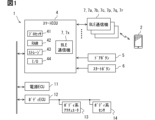
- FIG. 1 is a block diagram showing an overview of a vehicle electronic key system
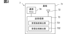
- FIG. 1 is a block diagram showing the configuration of a BLE communication device
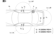
- FIG. 3 is a diagram illustrating an example of a mounting position of a BLE communication device
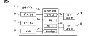
- 1 is a block diagram showing the configuration of a portable device
- 4 is a flowchart of standby processing
- It is a flowchart about the inside-and-outside determination process.
- FIG. 2 is a diagram for explaining an outline of a sniffing method
- FIG. It is a flowchart about locking/unlocking area determination processing.
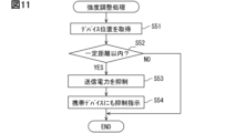
- 4 is a flowchart of strength adjustment processing
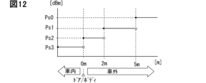
- FIG. 4 is a diagram illustrating an example of a mode of adjusting transmission power according to device position;
- FIG. 10 is a diagram showing a modification of the mounting pattern of the BLE communication device;
- FIG. 10 is a diagram showing a modification of the mounting pattern of the BLE communication device;
- FIG. 10 is a diagram showing a modification of the mounting pattern of the BLE communication device;
- FIG. 10 is a diagram showing a modification of the mounting pattern of the BLE communication device;
- FIG. 10 is a diagram showing a modification of the mounting pattern of the BLE communication device; It is a flowchart about the modification of locking/unlocking area determination processing.
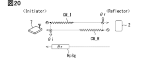
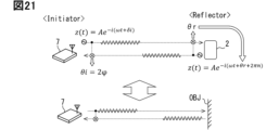
- FIG. 10 is a diagram showing an example of variations of device position estimation materials and their observers; It is a figure for demonstrating the calculation principle of the transmission-and-reception phase difference by a passive 2 way system.
- FIG. 4 is a diagram for explaining the principle of calculating a transmission/reception phase difference by an active 2-way method; It is a figure for demonstrating the calculation principle of the transmission-and-reception phase difference by a 1 way system.
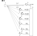
- 1 is a diagram showing an example of a configuration of an in-vehicle system 1 capable of transmitting wake signals;
- FIG. 1 is a diagram showing a system configuration example for estimating the position of a portable device using a UWB communication device;
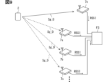
- FIG. 1 is a diagram showing an example of a schematic configuration of a vehicle electronic key system.
- the vehicle electronic key system includes an in-vehicle system 1 and a portable device 2 .
- the in-vehicle system 1 is a system installed in a vehicle Hv.
- the mobile device 2 is a device carried by the user of the vehicle Hv.
- a plurality of portable devices 2 may exist.
- a vehicle electronic key system corresponds to a position determination system.
- a vehicle Hv in the following description is a vehicle owned by an individual as an example. Therefore, the user of the vehicle Hv refers to the owner, his family, and the like.
- the vehicle Hv may be a company car owned by a company or a public car owned by a public institution. If the vehicle Hv is a company car or public vehicle, the user can be a person who belongs to an organization that manages the vehicle Hv.
- the vehicle Hv may be a vehicle provided for a rental service (so-called rental car) or a vehicle provided for a car-sharing service (so-called shared car).
- the vehicle Hv may be a vehicle provided for passenger transportation services, such as a robot taxi.
- the vehicle Hv is a vehicle provided for the above services (hereinafter referred to as a service vehicle), a contract for the use of those services has been made, and based on the reservation for use of the service, etc., the vehicle Hv is temporarily used.
- a person who has the right to use can be a user.
- the vehicle Hv is an engine vehicle as an example.
- the vehicle Hv may be a hybrid vehicle or an electric vehicle such as an electric vehicle.
- the engine vehicle here refers to a vehicle having only an engine as a power source
- the hybrid vehicle refers to a vehicle having both an engine and a motor as power sources.
- Engine vehicles include diesel vehicles.
- An electric vehicle refers to a vehicle having only a motor as a drive source.
- the vehicle Hv is a vehicle with a driver's seat on the right side, but the vehicle Hv may be a vehicle with a driver's seat on the left side.
- the directions of front and rear, left and right, and up and down are defined with respect to the vehicle Hv.
- the longitudinal direction corresponds to the longitudinal direction of the vehicle Hv.
- the left-right direction corresponds to the width direction of the vehicle Hv.
- the vertical direction corresponds to the height direction of the vehicle Hv.
- the present disclosure is not limited to four-wheeled vehicles, and can be mounted on various vehicles that can travel on roads, such as trailers, two-wheeled vehicles, and three-wheeled vehicles.
- a motorized bicycle can also be included in a two-wheeled vehicle.
- Both the in-vehicle system 1 and the portable device 2 are configured to be capable of short-distance communication.
- the short-range communication here refers to communication conforming to a predetermined short-range wireless communication standard with a substantial communicable distance of, for example, 5m to 30m, and a maximum of about 100m.
- BLE Bluetooth Low Energy
- Wi-Fi registered trademark
- ZigBee registered trademark
- UWB-IR Ultra Wide Band-Impulse Radio
- each part will be described by taking as an example a case where the in-vehicle system 1 and the mobile device 2 are each configured to be able to perform wireless communication (hereinafter referred to as BLE communication) conforming to the BLE standard.
- BLE communication wireless communication
- Details of communication methods such as communication connection and encryption communication are implemented according to the sequence defined by the BLE standard.
- the BLE communication device 7 mounted on the vehicle Hv acts as a master in communication with the mobile device 2 and the mobile device 2 acts as a slave.
- a slave in BLE communication is a device that intermittently transmits an advertisement signal and transmits and receives data based on a request from the master. Slaves are also called peripherals.
- a master is a device that controls the communication connection state and communication timing with a slave.
- a master is also referred to as a central.
- the mobile device 2 may be set to operate as a master in communication with the in-vehicle system 1 .
- the advertising signal is a signal for notifying (that is, advertising) the existence of itself to other devices.
- the advertising signal can be called an advertising frame or an advertising packet.
- a signal transmitted and received by BLE, such as an advertisement signal includes source information.
- the source information is, for example, unique identification information (hereinafter referred to as device ID) assigned to the mobile device 2 .
- device ID for example, a device address or UUID (Universally Unique Identifier) can be adopted.
- a device address in Bluetooth can be represented by 48 bits. Also, the UUID can be expressed in 128 bits.
- a device address may be a fixed public address or a random address.
- a public address corresponds to a MAC (Media Access Control) address in Ethernet (registered trademark).
- the portable device 2 is a device that holds key information for using the vehicle Hv and functions as an electronic key for the vehicle Hv using the key information.
- the key information here is data used in authentication processing, which will be described later.
- the key information is data for proving that the person trying to access the vehicle Hv is the user, that is, the legitimacy of the person trying to access the vehicle Hv.
- Key information can be called an authentication key, an encryption key, or a key code.
- the key information can be, for example, a character string (value) encrypted by putting a password set by the user into a predetermined hash function. Key information may be generated based on the device ID.
- the key information can be different for each mobile device 2.
- key information for each portable device 2 is stored and registered in association with a device ID.
- a plurality of portable devices 2 may be distinguished by key IDs assigned in order of registration instead of device IDs.
- the device ID can be represented by a length of about 48 bits (6 bytes)/128 bits (16 bytes), while the key ID can be represented by several bytes such as 1 byte.
- the key information itself can be represented by a bit string having a length of 8 bits or more. The longer the key information, the stronger the security, which is preferable.
- Key information can be represented by, for example, 16 bytes or 27 bytes. According to the configuration in which the key information is 27 bytes or less, it is possible to transmit all the key information in one packet in encrypted communication.
- the in-vehicle system 1 performs automatic authentication processing with the portable device 2 through wireless communication. Then, the in-vehicle system 1 realizes a passive entry passive start system that performs vehicle control according to the position of the user with respect to the vehicle Hv on condition that the authentication is successful. Vehicle control here includes door locking/unlocking, power on/off, engine starting, and the like.
- the vehicle-mounted system 1 opens the door on the basis of a user operation on the door button 5 described later. Executes control such as locking and unlocking of the Further, when the in-vehicle system 1 confirms that the portable device 2 is present in the vehicle compartment by wireless communication with the portable device 2, the in-vehicle system 1 performs engine start control based on the user's operation of the start button 6, which will be described later. to run.
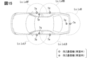
- the locking/unlocking area Lx is an area for the in-vehicle system 1 to execute predetermined vehicle control such as locking and unlocking the doors based on the presence of the portable device 2 in the area.
- the locking/unlocking area Lx is a type of outdoor operation area and can also be called a passive entry area.
- the vicinity of the door for the driver's seat, the vicinity of the door for the passenger's seat, and the vicinity of the trunk door are set as the locking/unlocking areas Lx.
- the vicinity of the door refers to a range within a predetermined working distance from the outer door handle.
- the outer door handle refers to a gripping member provided on the outer surface of the door for opening and closing the door.
- the working distance that defines the size of the locking/unlocking area Lx is, for example, 1.5m. Of course, the working distance may be 1 m or 0.7 m. The working distance is set smaller than 2 m from the viewpoint of security.
- an area outside the vehicle compartment outside the locking/unlocking area Lx will be referred to as a non-operating area.
- the non-operating area may include an unlocking prohibited area that is more than 2m away from the vehicle.
- the authentication of the portable device 2 by the in-vehicle system 1 can be performed by, for example, a challenge-response method.
- the authentication process involves matching the response code generated by the portable device 2 based on the key information with the verification code retained or dynamically generated by the vehicle Hv, so it can also be called a matching process. Details of the authentication process will be described separately later.
- Successful authentication of the portable device 2 corresponds to determining that the person attempting to access the vehicle Hv is a legitimate user.
- the in-vehicle system 1 includes a smart ECU 4, a plurality of door buttons 5, a start button 6, a plurality of BLE communication devices 7, a power supply ECU 11, a body ECU 12, a body system actuator 13, and a body system sensor 14, as shown in FIG. .
- the ECU in the member name is an abbreviation for Electronic Control Unit and means an electronic control unit.
- the smart ECU 4 is connected to each of the door button 5, the start button 6, and the BLE communication device 7 via dedicated signal lines.
- the smart ECU 4 is also connected to the power supply ECU 11, the body ECU 12, and the like via an in-vehicle network Nw so as to be able to communicate with each other.
- the in-vehicle network Nw is a communication network built in the vehicle Hv.
- As the standard of the in-vehicle network Nw various standards such as Controller Area Network (hereafter, CAN: registered trademark) and Ethernet can be adopted.
- a part of the body ECU 12 and the like may be connected to the smart ECU 4 via a dedicated line without passing through the in-vehicle network Nw. The form of connection between devices can be changed as appropriate.
- the smart ECU 4 estimates the position of the portable device 2 in cooperation with the BLE communication device 7 and the like. In addition, the smart ECU 4 realizes vehicle control according to the estimation result of the position of the mobile device 2 in cooperation with other ECUs. Smart ECU4 is implement
- the processor 41 is hardware for arithmetic processing (in other words, arithmetic core) coupled with a RAM (Random Access Memory) 42 .
- the processor 41 is, for example, a CPU (Central Processing Unit).
- the processor 41 accesses the RAM 42 to execute various processes for realizing the functions of the functional units, which will be described later.
- RAM 42 is a volatile storage medium.
- the storage 43 is configured to include a non-volatile storage medium such as flash memory.
- Various programs executed by the processor 41 are stored in the storage 43 . Execution of the program by the processor 41 corresponds to execution of a method corresponding to the program, for example, a device position estimation method.
- the I/O 44 is a circuit module for communicating with other devices. The I/O 44 is implemented using an analog circuit element, an IC, or the like.
- a device ID for each portable device 2 is registered in the storage 43 .
- the storage 43 stores communication device setting data indicating the mounting position of each BLE communication device 7 in the vehicle Hv.
- the storage 43 corresponds to a storage device in which communication device setting data is stored.
- the mounting position of each BLE communication device 7 is, for example, expressed as a point on a vehicle coordinate system, which is a two-dimensional coordinate system centered on an arbitrary position of the vehicle Hv and parallel to both the width direction and the front-rear direction of the vehicle Hv. sell.
- the X-axis forming the vehicle coordinate system can be set parallel to the width direction of the vehicle, and the Y-axis can be set parallel to the longitudinal direction of the vehicle.
- the center of the coordinate system for example, the center of the vehicle body or the center of the rear axle can be used.
- a unique communication device number is set for each BLE communication device 7 provided in the in-vehicle system 1 .
- the communication device number functions as information for identifying multiple BLE communication devices 7 .
- the installation position of each BLE communication device 7 is stored as communication device setting data in association with the communication device number. Details of the functions of the smart ECU 4 will be described separately later.
- the door button 5 is a button for the user to unlock and lock the door of the vehicle Hv.
- the door button 5 is provided on or near the outer door handle provided on each door. When the door button 5 is pressed by the user, it outputs an electric signal to that effect to the smart ECU 4 .
- a touch sensor may be employed as a configuration for receiving at least one of the user's unlocking instruction and locking instruction.
- a touch sensor is a device that detects that a user is touching the door handle.
- a touch sensor may be provided on the outer door handle instead of the door button 5 or together with the door button 5 .
- the start button 6 is a push switch for the user to turn on/off the running power supply.
- the running power source is a power source for the vehicle Hv to run, and indicates an ignition power source when the vehicle is an engine vehicle.
- the running power supply refers to the system main relay.
- the start button 6 can also be understood as a switch for starting a drive source (for example, an engine). When the start button 6 is pushed by the user, it outputs an electrical signal to the smart ECU 4 to indicate that.
- the BLE communication device 7 is a communication module for performing wireless communication with the mobile device 2 in accordance with the BLE standard.
- Each BLE communication device 7 includes a substrate 71, an antenna 72, a transceiver 73, and a communication microcomputer 74, as shown in FIG.
- the substrate 71 is, for example, a printed circuit board.
- the substrate 71 is provided with electronic components that configure the BLE communication device 7, such as an antenna 72, for example.
- Antenna 72 is an antenna for transmitting and receiving radio waves in the frequency band used for BLE communication, that is, the 2.4 GHz band.
- the 2.4 GHz band corresponds to an example of the predetermined frequency band. Note that the frequency band used for BLE communication is from 2400 MHz to 2483.5 MHz.
- the antenna 72 is electrically connected to the transmitting/receiving section 73 .
- the antenna 72 may be an array antenna formed by arranging a plurality of antenna elements.
- the transmitting/receiving section 73 demodulates the signal received by the antenna 72 and provides it to the communication microcomputer 74 . Also, a signal input from the smart ECU 4 via the communication microcomputer 74 is modulated, output to the antenna 72, and radiated as radio waves.
- the transmission/reception unit 73 is connected to the communication microcomputer 74 so as to be able to communicate with each other.
- the transmitting/receiving section 73 includes a reception intensity detection section 731 and a reception phase detection section 732 .
- the reception strength detector 731 is configured to sequentially detect the strength of the signal received by the antenna 72 .
- the signal indicating the reception strength detected by the reception strength detection unit 731 or the measured value itself can also be called RSSI (Received Signal Strength Indicator/Indication).
- RSSI Received Signal Strength Indicator/Indication
- the reception strength detected by the reception strength detector 731 is sequentially provided to the communication microcomputer 74 in association with the device ID indicating the transmission source of the received signal.
- the reception phase detection unit 732 detects the reception phase, which is the phase angle of the reception signal with respect to the output signal of the local oscillator.
- the reception phase corresponds to, for example, the output value of the arctangent whose input value is the ratio of the Q (Quadrature-Phase) component to the I (In-Phase) component of the reception signal.
- the magnitude of the I component corresponds to the strength of the in-phase component of the received signal.
- the magnitude of the Q component corresponds to the strength of the quadrature component of the received signal.
- the I component is obtained by multiplying the received signal by the carrier output by the local oscillator.
- the Q component is obtained by multiplying the received signal by a phase-shifted signal obtained by shifting the phase of the output signal of the local oscillator by 90°.
- a phase-shifted signal can be obtained by passing the output signal of the local oscillator through a phase-shift circuit, which is a circuit that shifts the phase by 90°.
- a local oscillator is a circuit that generates a sine wave or cosine wave of a carrier frequency, and is implemented using, for example, a voltage-controlled oscillator (VCO).
- VCO voltage-controlled oscillator
- the phase detected by the reception phase detector 732 is output to the communication microcomputer 74 in association with the frequency of the reception signal.
- the receive phase may be determined based on the IQ signal down frequency to baseband.
- the communication microcomputer 74 is a microcomputer that controls the exchange of data with the smart ECU 4.
- the communication microcomputer 74 is implemented using a CPU, RAM, ROM (Read Only Memory), and the like.
- the communication microcomputer 74 provides the smart ECU 4 with the reception data input from the transmission/reception unit 73 sequentially or based on a request from the smart ECU 4 .
- the communication microcomputer 74 has a function of authenticating the device ID of the mobile device 2 and performing cryptographic communication with the mobile device 2 based on a request from the smart ECU 4 .
- Various methods can be used as the encryption method.
- the communication microcomputer 74 outputs data indicating the reception intensity detected by the reception intensity detection unit 731 based on the request from the smart ECU 4 to the smart ECU 4 . Note that the communication microcomputer 74 may sequentially output the reception intensity data to the smart ECU 4 regardless of the presence or absence of a request from the smart ECU 4 . The communication microcomputer 74 outputs the phase information of the received signal for each frequency to the smart ECU 4 voluntarily or based on an instruction from the smart ECU 4, similarly to the reception intensity.
- At least one BLE communication device 7 is provided in the vehicle Hv.
- one BLE communication device 7 is built in the smart ECU 4 as an example.
- a plurality of BLE communication devices 7 are also distributed outside the smart ECU 4 at a plurality of locations on the vehicle.
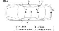
- BLE communication devices 7a to 7c, 7p to 7r, and 7x are provided.
- the BLE communication device 7a is provided on the outer surface of the B-pillar on the right side door.
- the BLE communication device 7b is provided on the outer surface of the B pillar in the left door.
- the BLE communication devices 7a and 7b are arranged in an area within 30 cm above the beltline in the B pillars of the left and right doors.
- the beltline is a line along the lower edge of the side window and may also be called a waistline.
- the BLE communication device 7c is arranged in the center of the rear bumper in the left-right direction.
- the BLE communication devices 7a to 7c correspond to the outdoor unit, which is the BLE communication device 7 provided on the outer surface of the vehicle.
- the BLE communication devices 7a to 7c as outdoor units correspond to a configuration for receiving signals mainly from the portable device 2 existing outside the vehicle.
- the outdoor unit is preferably arranged near the B-pillar or the outer door handle so that the signal from the portable device 2 carried by the user who is going to board the vehicle Hv can be well received.
- each outdoor unit forms an individual locking/unlocking area Lx.
- the BLE communication device 7a forms a right side area LxR which is a locking/unlocking area Lx on the right side of the vehicle.
- the BLE communication device 7b forms a left side area LxL which is a left locking/unlocking area Lx.
- the BLE communication device 7c forms a rear area LxB that is a locking/unlocking area Lx near the rear end.
- the B-pillar includes the door-side B-pillar provided in the door module and the vehicle-body-side B-pillar as a strut/frame provided with the roof of the vehicle body.
- the door-side B-pillar corresponds to a portion of the front-seat door or the rear-seat door that comes into contact with the vehicle-body-side pillar.
- the B-pillar below mainly refers to the door-side B-pillar.
- the door-side B-pillar as the installation position of the outdoor unit refers to the portion adjacent to the side window, that is, the portion above the lower end of the side window.
- the outdoor unit may be arranged in a portion below the window frame of the B-pillar on the door side or in the B-pillar on the vehicle body side.
- the B pillar refers to the second pillar from the front among the pillars provided in the vehicle Hv.
- the B-pillar may also be called a center pillar.
- the third pillar from the front or behind the rear seats is called the C pillar.
- the A pillar is the frontmost pillar and corresponds to the pillar positioned in front of the front seats.
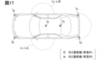
- the BLE communication device 7p is arranged at a position that is 0.1 m or more below the window on the inner side of the metal panel that constitutes the right front door.
- the BLE communication device 7p is arranged in an area within 20 cm from the floor on the interior side surface of the right front door.
- the right front door refers to the door for the right front seat.
- the BLE communication device 7q is arranged at a position corresponding to the BLE communication device 7p on the left side of the vehicle. That is, the BLE communication device 7q is arranged at a position lower than the window by 0.1 m or more on the vehicle-interior side surface of the metal panel that constitutes the left front door.
- the left front door refers to a front seat door provided on the left side of the vehicle.
- the BLE communication device 7r is provided in the trunk or on the back of the backrest of the rear seat.
- the BLE communication devices 7p to 7r correspond to the indoor units that are the BLE communication device 7 provided inside the vehicle.
- the BLE communication devices 7p to 7r as indoor units correspond to a configuration for receiving signals mainly from the portable device 2 present inside the vehicle.
- a non-line-of-sight area for a certain BLE communication device 7 is an area where a signal transmitted from the BLE communication device 7 does not directly reach. It should be noted that the signal transmitted from the BLE communication device 7 may reach beyond the line of sight by being reflected by various structures. In other words, even if the mobile device 2 is out of line of sight of the BLE communication device 7, the two can perform wireless communication due to reflection, diffraction, or the like from structures.
- the indoor unit is positioned away from the position where it is paired with the outdoor unit with a metal plate such as a door in between.
- the paired positions refer to positions that are in a front-to-back relationship with the metal body interposed therebetween. More specifically, a range in which the distance from the outdoor unit is less than 20% of the target wavelength can correspond to a position paired with the outdoor unit. Therefore, the indoor unit is located at a distance of 20% or more, more preferably 40% or more of the target wavelength from the outdoor unit.
- the target wavelength here is the wavelength of the signal provided for BLE communication, which is approximately 122 mm. Therefore, 20% of the target wavelength is approximately 2.5 cm, and 40% is approximately 5 cm.
- the arrangement mode described above corresponds to a configuration in which the indoor unit is arranged at a position separated from the outdoor unit by at least 10 cm in the vertical direction or the front-rear direction.
- the BLE communication device 7x is built into the smart ECU 4.
- FIG. 3 shows a mode in which the smart ECU 4 is attached to the right C-pillar as an example.
- the smart ECU 4 may be housed inside the instrument panel.
- the smart ECU 4 can be accommodated inside the upper surface of the instrument panel, inside the center garnish, or the like.
- the BLE communication device 7x is preferably positioned so as to be able to communicate not only inside the vehicle but also with the portable device 2 outside the vehicle.
- the smart ECU 4 including the BLE communication device 7x may be arranged at a position where the outside of the vehicle can be seen through a window, such as the ceiling of the vehicle. Also, the BLE communication device 7 x may be arranged separately from the smart ECU 4 .
- the mounting position of the BLE communication device 7 described above is an example, and can be changed as appropriate.
- the BLE communication devices 7a and 7b as outdoor units may be built in the outer door handle for the front seats, or may be arranged in the locker portion under the door.
- the rocker portion also includes the inner portion of the side sill cover.
- the mounting position of the BLE communication device 7c may be near the rear license plate, near the rear window, near the door handle for the trunk, or the like.
- “near” a certain member refers to a range within, for example, 30 cm from the member.
- near the license plate refers to a range within 30 cm from the license plate.
- Near the door handle also includes the interior of the door handle.
- the BLE communication devices 7p and 7q as indoor units may be arranged at the base of the B-pillar on the vehicle body side or near the feet of the driver's seat and the passenger's seat.
- the base of the B-pillar on the vehicle body side refers to the part within 20 cm from the floor.
- the BLE communication devices 7p and 7q may be arranged near inner door handles, door switch panels, door pockets, armrests, and the like.
- the BLE communication device 7r may be buried in the center of the rear seat. Further, the number of BLE communication devices 7 included in the in-vehicle system 1 may be six or less, or may be eight or more.
- the in-vehicle system 1 may include a BLE communication device 7 arranged near the front bumper/emblem.
- the BLE communication devices 7 included in the in-vehicle system those used for data communication with the portable device 2 are referred to as representative devices or gateway communication devices in this disclosure.
- the BLE communication device 7x basically operates as a representative device.
- the representative machine settings can be dynamically changed by the processor 41 .
- the smart ECU 4 executes the key exchange protocol (so-called pairing) with the mobile device 2 using one of the plurality of BLE communication devices 7 .
- Device information which is information about the portable device 2 acquired by pairing, is stored in the storage 43 and also stored in a non-volatile memory included in the communication microcomputer 74 of each BLE communication device 7 .
- Device information is, for example, a key exchanged by pairing, a device ID, and the like. Note that when the vehicle Hv is shared by a plurality of users, device information is stored for each of the portable devices 2 owned by each user.
- the smart ECU 4 acquires in advance device information corresponding to a user who has made a reservation for use from a digital key server that issues key information, and temporarily stores the device information in a predetermined storage medium.
- the BLE communication device 7x and thus the in-vehicle system 1 receive a signal transmitted from the mobile device 2, such as an advertisement signal or a scan response signal, so that the mobile device 2 is within a range where short-range communication with the in-vehicle system 1 is possible. Detect that it exists.
- the scan response signal corresponds to the response signal issued by the slave in response to the scan request signal issued by the master.
- the portable device 2 existing around the vehicle is detected by a passive scanning method in which the BLE communication device 7x acts as a master.
- the in-vehicle system 1 may search for the portable device 2 using an active scanning method that involves sending scan requests. The two types of scanning methods may be used differently depending on the scene.
- the BLE communication device 7x When the BLE communication device 7x receives an advertise signal or a scan response signal from the mobile device 2, it automatically establishes a communication connection with the mobile device 2 using the saved device information. The smart ECU 4 then initiates encrypted data communication with the mobile device 2 . Note that, when the communication connection with the portable device 2 is established, the BLE communication device 7x provides the smart ECU 4 with the device ID of the connected portable device 2 as connected device information.
- the BLE communication device 7x as a representative device sequentially provides the communication control unit F2 with information indicating the channel used for communication with the portable device 2 (hereinafter referred to as channel information).
- the channel information may be a specific channel number, or may be a parameter (so-called hopIncrement) indicating a transition rule of the used channel.
- HopIncrement is a number from 5 to 16 that is randomly determined at the time of communication connection.
- the channel information preferably includes the current channel number and HopIncrement.
- Each BLE communication device 7 provided outside the smart ECU 4 is connected to the smart ECU 4 via a dedicated communication line or an in-vehicle network Nw so as to be able to communicate with each other.
- Each BLE communication device 7 operates based on a control signal from the communication control unit F2 provided in the smart ECU 4 . Further, each BLE communication device 7 provides the smart ECU 4 with received data and information on the reception status of signals from the portable device 2 . Information about the reception status of the signal from the mobile device 2 will be described separately later.
- the power supply ECU 11 is an ECU that controls the on/off state of the traveling power supply mounted on the vehicle Hv. For example, the power supply ECU 11 turns on the driving power supply based on an instruction signal from another ECU such as the smart ECU 4 or the body ECU 12 . When the vehicle Hv is an engine vehicle, the power supply ECU 11 starts the engine based on the instruction signal.
- the body ECU 12 is an ECU that controls the body system actuator 13 based on requests from the smart ECU 4 and the user.
- the body ECU 12 is communicably connected to various body system actuators 13 and various body system sensors 14 .
- the body system actuator 13 here is, for example, a door lock motor that constitutes a lock mechanism for each door.
- the body system sensor 14 includes a courtesy switch and the like arranged for each door.
- a courtesy switch is a sensor that detects opening and closing of a door.
- the body ECU 12 locks and unlocks each door by outputting a predetermined control signal to a door lock motor provided for each door of the vehicle Hv based on a request from the smart ECU 4, for example.
- the mobile device 2 is a portable general-purpose information processing terminal having a BLE communication function.
- a digital key application 204 which is an application for functioning as an electronic key for the vehicle Hv, is installed.
- the portable device 2 for example, a smart phone, a tablet terminal, a wearable device, or the like can be adopted.
- a wearable device is a device worn on a user's body for use, and can be of various shapes such as a wristband type, a wristwatch type, a ring type, an eyeglass type, and an earphone type.
- the portable device 2 may be a smart key that is a dedicated device as an electronic key for the vehicle Hv.
- the smart key is a device that is given to the owner together with the vehicle Hv when the vehicle Hv is purchased.
- a smart key can be understood as one of the accessories of the vehicle Hv.
- the smart key can adopt various shapes such as a flat cuboid shape, a flat ellipsoid shape (so-called fob type), and a card shape.
- a smart key may be referred to as a vehicle handheld, key fob, key card, access key, or the like.
- the mobile device 2 includes a device control unit 20, a display 21, a touch panel 22, a battery 23, a BLE communication unit 24, and a cellular communication unit 25, as shown in FIG.
- the display 21 is, for example, a liquid crystal display or an organic EL display.
- a display 21 displays an image corresponding to an input signal from the device control section 20 .
- the touch panel 22 is a capacitive touch panel and laminated on the display 21 .
- the touch panel 22 and the display 21 correspond to interfaces for the user to register key information in the mobile device 2 and pair the mobile device 2 with the in-vehicle system 1 .
- the battery 23 is a secondary battery such as a lithium ion battery.
- the BLE communication unit 24 is a communication module for implementing BLE communication.
- a schematic configuration of the BLE communication unit 24 can be the same as that of the BLE communication device 7 .
- the BLE communication unit 24 is connected to the device control unit 20 so as to be able to communicate with each other.
- the BLE communication unit 24 receives data transmitted from the vehicle Hv and provides it to the device control unit 20, modulates data input from the device control unit 20, and transmits the modulated data to the vehicle Hv.
- the cellular communication unit 25 is a communication module for connecting to the Internet via a wireless base station, and is configured to be able to perform wireless communication conforming to standards such as 4G and 5G.
- the cellular communication unit 25 can receive a data package for installing the digital key application 204 from a predetermined application distribution server, for example.
- the cellular communication unit 25 is an optional element and may be omitted.
- the mobile device 2 may be configured to be able to access the Internet via a Wi-Fi line instead of a cellular line such as 4G or 5G.
- the device control unit 20 is configured as a computer including, for example, a processor 201, a RAM 202, a storage 203, and the like.
- a digital key application 204 is installed in the storage 203 or the like. Further, the storage 203 stores key information.
- the digital key application 204 is an application for securely performing key information acquisition, storage, authentication processing, and the like.
- Digital key app 204 is an optional element and may be omitted.
- the device control unit 20 causes the BLE communication unit 24 to transmit the advertisement signal at predetermined transmission intervals.
- the mobile device 2 may transmit a scan response based on a request from the in-vehicle system 1, for example, a scan request.
- the device control unit 20 when receiving data from the BLE communication unit 24 , the device control unit 20 generates a baseband signal corresponding to a response signal corresponding to the received data, and outputs the baseband signal to the BLE communication unit 24 .
- the BLE communication unit 24 receives a challenge code, it generates a response code using a predetermined procedure/function based on the challenge code and key information. Then, it outputs a baseband signal including the response code to the BLE communication unit 24 .
- the baseband signal output from the device control unit 20 to the BLE communication unit 24 is modulated by the BLE communication unit 24 and transmitted as a radio signal.
- the device control unit 20 does not have to return the response code during the pause period set by the user. According to this configuration, it is possible to reduce the possibility that authentication will succeed when the user has no intention of using the vehicle Hv.
- the idle time period can be manually set by the user so as to correspond to a time period during which there is no possibility of using the vehicle Hv. For example, the time period during which the user sleeps, the time period during which the user goes to school or work, and the like can be set as the idle time period.
- the pause time period may be automatically registered from the user's action history information. A user's action history can be specified based on the location information of the portable device 2, such as GPS.
- the device control unit 20 may be configured not to return a response code when the portable device 2 is stationary for a certain period of time or longer. Whether or not the portable device 2 is stationary can be specified based on the output of an acceleration sensor or a gyro sensor provided in the portable device 2, for example.
- the device control unit 20 may stop transmission of advertisements for the vehicle Hv during the downtime. According to such a configuration, power consumption due to unnecessary advertising can be suppressed. Further, when the operation of the BLE communication unit 24 can be controlled on an application-by-application basis, the device control unit 20 may stop transmission of advertisements for the vehicle Hv based on the mobile device 2 being stationary for a certain period of time or longer. good. Further, the device control unit 20 may be configured to prohibit communication connection with the in-vehicle system 1 based on the fact that the device is in a downtime period or has been stopped for a certain period of time or more.
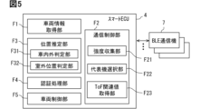
- the smart ECU 4 provides functions corresponding to various functional blocks shown in FIG. 5 by executing programs stored in the storage 43 . That is, smart ECU4 is provided with the vehicle information acquisition part F1, the communication control part F2, the position estimation part F3, the authentication process part F4, and the vehicle control part F5 as a functional block.
- the communication control unit F2 includes, as sub-function units, an intensity collection unit F21, a representative machine selection unit F22, and a ToF related value acquisition unit F23.
- the position estimating unit F3 includes a vehicle interior/exterior determination unit F31 and a vehicle exterior position determination unit F32 as sub-function units.
- the smart ECU 4 also includes a key information storage unit M1.
- the key information storage unit M1 is a storage medium for storing information of the portable device 2 used as an electronic key for the vehicle Hv. Information about at least one mobile device 2 is stored in the key information storage unit M1. Key information for each portable device 2 is stored in the key information storage unit M1 in association with a key ID, device ID, user ID, and the like.
- a user ID is an identifier for identifying a plurality of users and is set for each user. Information such as an expiration date, authority, and seat position may be associated with the key information and stored.
- the key information storage unit M1 is implemented using part of the storage area of the storage 43. Note that the key information storage unit M1 may be implemented using a non-volatile storage medium that is physically independent of the storage 43 .
- the key information storage unit M1 is configured so that the processor 41 can write, read, and delete data.
- the vehicle information acquisition unit F1 acquires various vehicle information indicating the state of the vehicle Hv from sensors, ECUs, switches, etc. mounted on the vehicle Hv.
- the vehicle information includes the state of the power source of the vehicle, the open/closed state of each door, the locked/unlocked state of each door, whether the door button 5 has been pressed, whether the start button 6 has been pressed, and the shift position.
- the state of the vehicle power supply includes whether or not the running power supply is on.
- the types of vehicle information are not limited to those described above.
- the vehicle information can also include an output value of a brake sensor that detects the depression amount/depression force of the brake pedal and a signal that indicates the operating state of the parking brake.
- the vehicle information acquisition unit F1 identifies the current state of the vehicle Hv based on the various information described above. For example, the vehicle information acquisition unit F1 determines that the vehicle Hv is parked when the engine is off and all the doors are locked. The condition for determining that the vehicle Hv is parked may be appropriately designed, and various determination conditions are applicable. Acquiring electrical signals from the door button 5 and the start button 6 corresponds to detecting user operations on these buttons. The vehicle information acquisition unit F1 detects user operations on the vehicle Hv, such as opening and closing the door, pressing the door button 5, pressing the start button 6, and opening and closing the door.
- the communication control unit F2 controls the operation of the BLE communication device 7.
- the communication control unit F2 performs data communication with the portable device 2 using the BLE communication device 7x.
- the communication control unit F2 generates data addressed to the mobile device 2 connected for communication, and outputs the data to the BLE communication device 7x.
- a signal corresponding to desired data is transmitted as radio waves.
- the communication control unit F2 receives data from the mobile device 2 received by the BLE communication device 7x.
- wireless communication between the smart ECU 4 and the portable device 2 is encrypted as a more preferable aspect.
- the communication control unit F2 recognizes that the user exists around the vehicle Hv based on the reception of the BLE signal transmitted from the mobile device 2. In addition, the communication control unit F2 acquires the device ID of the mobile device 2 connected for communication from the BLE communication device 7x. Even if the vehicle Hv is shared by a plurality of users, the smart ECU 4 identifies users around the vehicle Hv based on the device IDs of the portable devices 2 to which the BLE communication device 7 is connected.
- the communication control unit F2 acquires the reception strength for each frequency of the signal from the portable device 2 from each BLE communication device 7.
- a configuration that acquires the reception strength for each frequency and for each communication device corresponds to the strength collection unit F21.
- the communication control unit F2 can temporarily change the representative device to determine the position of the portable device 2.
- the state in which the BLE communication device 7x is set as the representative device will be referred to as the basic state.
- a state in which the BLE communication device 7 other than the BLE communication device 7x is set as the representative device is referred to as a temporary change state.
- a sub-function unit that changes the representative device corresponds to the representative device selection unit F22.
- the communication control unit F2 acquires at least the ToF-related value based on the representative device by causing the arbitrary BLE communication device 7 as the representative device to communicate with the portable device 2 for distance measurement.
- the ToF-related value is a parameter that directly or indirectly indicates the flight time of radio waves from the BLE communication device 7 to the mobile device.
- Communication for ranging is communication for measuring the distance from the BLE communication device 7 as a representative device to the mobile device 2 .
- the distance from the BLE communication device 7 to the mobile device 2 corresponds to the time of flight (ToF) of the signal. Identifying the distance to the mobile device 2 is equivalent to identifying the ToF.
- ToF is determined based on the two-frequency phase difference and round-trip time (RTT: Round-Trip Time).
- Two-frequency phase difference and RTT correspond to ToF-related values.
- ToF-related values can also be referred to as distance-related values.
- These ToF-related values are parameters different from the reception strength.
- the two-frequency phase difference here is the difference between transmission and reception phase differences observed at two frequencies different from each other.
- the two-frequency phase difference corresponds to the phase angle displacement due to frequency change.
- the transmission/reception phase difference corresponds to the phase difference between the transmitted CW signal and the received CW signal.
- the transmit/receive phase difference can also simply be called a phase angle.
- the two-frequency phase difference and the transmission/reception phase difference are conceptually the same as what is known as the two-frequency CW system in the technical field of ranging systems using radio waves.
- a two-frequency phase difference for each combination of frequencies is adopted.
- BLE communication since there are two or more frequencies used for communication, two or more two-frequency phase differences with different combinations of frequencies, ie, multi-frequency phase differences are obtained.
- the smart ECU 4 of this embodiment estimates the device distance based on the multi-frequency phase difference.
- communication for ranging can be understood as communication for specifying transmission and reception phase differences for each of two or more frequencies. Transmitting and receiving CW signals on multiple frequencies may correspond to communication for ranging.
- the representative communication microcomputer 74 observes the reception phase at the working frequency each time frequency hopping is performed. Further, the communication microcomputer 74 identifies the transmission/reception phase difference based on the observed reception phase.
- the processor 41 acquires the transmission/reception phase difference for each frequency from the communication microcomputer 74 of the representative device.
- the calculation of the transmission/reception phase difference may be performed by the processor 41 based on the reception phase information provided by the communication microcomputer 74. Acquisition of data in the present disclosure includes not only input from the outside but also generation/detection by internal calculation. Furthermore, the processor 41 obtains a plurality of sets of two-frequency phase differences for each combination of frequencies by combining the transmission and reception phase differences for each frequency. A sub-function unit that acquires the transmission/reception phase difference and thus the two-frequency phase difference corresponds to the ToF related value acquisition unit F23.
- the communication control unit F2 can acquire data indicating the reception phase of the CW signal for each frequency from other devices than the representative device.
- the communication control unit F2 also provides other function/circuit modules such as the position estimation unit F3 with data indicating the reception status of the signal from the portable device 2 in each BLE communication device 7 .
- the communication control unit F2 may acquire the direction of arrival of the signal as the information indicating the reception status of the signal from the mobile device 2 .
- the direction of arrival of a signal can be estimated by various methods such as the MUSIC method and the ESPRIT method. Received signal strength, phase, direction of arrival, etc. can be referred to as features of the received signal.
- the position estimation unit F3 estimates the position of the mobile device 2 based on the reception status of the signal from the mobile device 2 at each BLE communication device 7 .
- the location of mobile device 2 may also be expressed as device location. Since the mobile device 2 corresponds to the user, estimating the location of the mobile device 2 corresponds to estimating the location of the user.
- the position estimation unit F3 sequentially executes device position estimation processing at predetermined estimation intervals.
- the estimation interval can be 100 milliseconds.
- the estimation interval may be 200 milliseconds, 150 milliseconds, and so on.
- the position estimation processing by the position estimation unit F3 will be described separately later. Note that, when the position estimation unit F3 receives a signal from the mobile device 2, even if the position estimation unit F3 is configured to estimate the position of the transmission source based on the received signal, even if communication connection is not established. good.
- the position estimating unit F3 can perform processing for estimating the position of each of the plurality of portable devices 2 in parallel.
- the position estimator F3 may determine the position of not only the terminal registered as the mobile device 2 but also an unregistered terminal.
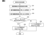
- a vehicle interior/exterior determination unit F31 as a sub-function unit of the position estimation unit F3 determines whether or not the mobile device 2 is present in the vehicle interior based on the reception strength of the signal from the mobile device 2 observed by the BLE communication device 7. It is a configuration for judging. Further, the vehicle exterior position determination unit F32 determines whether or not the mobile device 2 exists within the locking/unlocking area Lx based on the distance information from the outdoor unit to the mobile device 2, which is determined based on the ToF related value described later. It is a configuration that In the present disclosure, determining whether or not the mobile device 2 is present in the vehicle interior is also referred to as an in-vehicle/outside-vehicle determination.
- determining whether or not the portable device 2 is present in the locking/unlocking area Lx is also referred to as locking/unlocking area determination.
- the details of the operation of the position estimator F3/processor 41 as the vehicle interior/exterior determination unit F31 and the vehicle exterior position determination unit F32 will be described separately later.
- the authentication processing unit F4 cooperates with the BLE communication device 7x to perform processing to confirm (in other words, authenticate) that the communication partner is the portable device 2.
- Communication for authentication is encrypted.
- the authentication process itself may be performed using various methods such as a challenge-response method.
- the authentication processing unit F4 transmits a predetermined/randomly generated challenge code to the mobile device 2 .
- a verification code is generated according to a predetermined procedure using key information corresponding to the device ID/key ID of the communication partner in the challenge code. Then, the response code returned from the communication partner is compared with the verification code, and if the two match, it is determined that the authentication has succeeded.
- the timing at which the authentication processing unit F4 performs the authentication process can be, for example, the timing at which the communication connection between the BLE communication device 7 and the portable device 2 is established.
- the authentication processing unit F4 may be configured to perform authentication processing at predetermined intervals while the BLE communication device 7 and the mobile device 2 are connected for communication. Further, communication for authentication processing may be performed using a predetermined user operation on the vehicle Hv as a trigger, such as when the start button 6 is pressed by the user or when a door is opened and closed.
- the vehicle control unit F5 performs vehicle control according to the position of the portable device 2 (in other words, the user) and the state of the vehicle Hv on the condition that the authentication of the portable device 2 by the authentication processing unit F4 is successful. It is the structure which cooperates with ECU12 grade
- the state of the vehicle Hv is determined by the vehicle information acquisition unit F1.
- the device position is determined by the position estimator F3.
- the vehicle control unit F5 cooperates with the power supply ECU 11 when it is determined by the position estimation unit F3 that the portable device 2 is present in the vehicle interior and the start button 6 is pressed by the user. to start the engine.
- the vehicle interior can be called a passive start area.
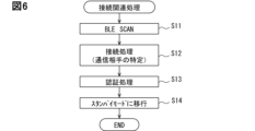
- connection-related processing is processing for communication connection with the mobile device 2 approaching the vehicle Hv together with the user.
- the connection-related processing is executed at predetermined scan intervals mainly while the vehicle Hv is parked.
- the scan interval can be set to 100ms, 200ms, and so on.
- the connection-related processing includes steps S11 to S15.
- the connection-related processing is performed by the processor 41 in cooperation with the BLE communication device 7x. Note that the various flowcharts of the present disclosure are all examples, and the number of steps and processing order included in each flowchart can be changed as appropriate.
- step S11 the communication control unit F2 sets the BLE communication device 7x to a standby state, and searches for the portable device 2 (so-called scanning).
- the standby state here refers to a state in which an advertising signal can be received. If no portable device 2 is detected as a result of the scanning in step S11, the process after step S12 is omitted and the flow ends.
- step S12 the BLE communication device 7x is connected for communication with the portable device 2 detected by scanning in step S11.
- a communication connection can be realized by exchanging the transmission of a connection request and its response.
- the processor 41 identifies the communication partner based on the source information and the like included in the advertising signal and the like. A detailed sequence from scanning to communication connection and start of encrypted communication may be executed in compliance with the BLE standard.
- step S12 for example, the challenge code and the key information of the communication partner stored in the key information storage unit M1 are used to authenticate the communication partner.
- a random number of a predetermined length generated using a random number table or the like can be used as the challenge code.
- the process moves to step S15 and shifts to the standby mode.
- the standby mode corresponds to a state in which unlocking/locking, on/off switching of the driving power supply, etc. can be performed based on the user's operation of the door button 5 or the like.
- Standby mode corresponds in one aspect to a state in which the processor 41 is aware that a legitimate mobile device 2 is present in the vicinity of the vehicle.
- the vehicle periphery includes the locking/unlocking area Lx and the vehicle interior.
- an expiration date is set for the determination result of successful authentication. Re-authenticate when the expiration date expires. Since the authentication process can be omitted within the validity period, power consumption in the portable device 2 and the smart ECU 4 can be suppressed. In addition, since the authentication process is executed for each expiration date, it is possible to reduce the risk of unauthorized use of the vehicle Hv.
- the expiration date may be changed depending on the scene such as whether the vehicle is running or not. Since it is unlikely that the portable device 2 will move out of the vehicle while the vehicle is running, the expiration date while the vehicle is running may be set to a predetermined amount longer than that while the vehicle is stopped.
- the validity period while stationary may be set to 1 second, 2 seconds, 5 seconds, etc.
- the validity period while driving may be set to 10 seconds, 20 seconds, etc.
- the authentication processing unit F4 may be configured to re-execute the authentication processing even if the validity period remains after detecting a predetermined event such as opening and closing of the door.
- the smart ECU 4 may re-execute the authentication process, or may operate the in-vehicle equipment so that the user can recognize that the authentication has not been successful. For example, when authentication is not successful, a predetermined authentication failure image may be displayed on the in-vehicle display/display 21, or a lighting device provided in a side mirror or the like may be lit in a predetermined pattern.
- the smart ECU 4 may display an authentication failure screen on the display 21 by transmitting a predetermined control signal when the authentication fails. Unsuccessful authentication may be expressed by the color of the illumination light of the welcome light that emits light toward the road surface around the door.
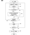
- the processor 41 sequentially acquires position estimation information, which is information for specifying the position of the portable device 2, from each BLE communication device 7 in step S21.
- the position estimation information is, for example, reception intensity.
- the reception phase can also be included in the position estimation information.
- the ToF-related value also corresponds to one type of position estimation information.
- the processor 41 determines that the mobile device 2 exists outside the vehicle, the processor 41 acquires the transmission/reception phase difference for each frequency or the two-frequency phase difference for each combination of frequencies as position estimation information from each outdoor unit. sell. Furthermore, in a system configuration that employs RTT as a ToF-related value, processor 41 can obtain RTT from each outdoor unit.
- the ToF-related value for each BLE communication device 7 can be obtained by causing a plurality of BLE communication devices 7 to sequentially carry out communication for distance measurement.
- each BLE communication device 7 does not perform two-way communication with the mobile device 2 individually, and the ToF-related value starting from each BLE communication device 7 is obtained. It is obtainable.
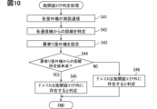
- Step S22 is a step in which the processor 41 (position estimation unit F3) determines the device position based on the position estimation information acquired from each BLE communication device 7 in step S21. Specifically, the processor 41 determines whether or not the device is located inside the vehicle interior, and if it determines that it is located outside the vehicle interior, determines whether or not it is within the locking/unlocking area Lx. Further, when determining that the portable device 2 exists within the locking/unlocking area Lx, the processor 41 exists in any of the right area LxR, the left area LxL, and the rear area LxB according to the ID of the nearest communication device. to identify A method for determining the device position will be described separately later.
- Step S22 is a step in which the processor 41 determines whether or not a predetermined user operation has been performed on the vehicle based on signals from the door button 5, the start button 6, the courtesy switch, and the like.
- the processor 41 executes vehicle control according to the member operated by the user, the device position, and the state of the vehicle Hv in step S24. For example, when the vehicle Hv is locked, the processor 41 (vehicle control unit F5) determines that the operating member is the door button 5 and the device position is within the locking/unlocking area Lx. unlock the Moreover, the processor 41 turns on the traveling power supply when the operation member is the start button 6 and the device position is also determined to be inside the vehicle.
- the processor 41 locks the door when the door button 5 is pressed while a predetermined locking condition is satisfied.
- the locking conditions include that the vehicle Hv is unlocked, that the driving power supply is turned off, that the shift position is set to parking or neutral, and that the device position is within the locking/unlocking area Lx. can be adopted.
- the vehicle control unit F5 can cancel the execution of vehicle control when the device position determined by the position estimation unit F3 and the operation button position do not match.
- the operation button position refers to the position of the button pressed by the user. The case where the device position and the operation button position do not match is, for example, when the portable device 2 is located away from the driver's seat, such as in the front passenger seat or near the trunk, and the driver's seat door button 5 is pressed. case applies. Also, when the start button 6 is pressed in a situation where it is determined that the mobile device 2 is outside the vehicle, the position of the mobile device 2 and the position of the operation button may not match. Note that when a touch sensor is applied instead of the button, the operation button position can be read as the touch position. The operation button position and touch position are included in the concept of the operation member position.
- a step S25 determines whether or not the validity period of the authentication result has expired, that is, whether or not a predetermined time has passed since the authentication was determined to be successful in step S14 or step S26 described later. If the predetermined time has not elapsed since the last determination of successful authentication, that is, if the expiration date has not passed, the process returns to step S21. On the other hand, if a predetermined period of time has elapsed since the last determination of successful authentication, the processor 41 executes communication for authenticating the portable device 2 again in step S26.
- the standby mode is continued. That is, the processes after step S21 are sequentially executed.
- the processor 41 cancels the standby mode in step S28. Note that the standby mode may be canceled based on the fact that authentication processing has failed a specified number of times in succession.
- the processor 41 may end the standby mode not only when the authentication fails, but also when it detects that the mobile device 2 has left the predetermined authentication state maintenance area. Terminating the standby mode corresponds to discarding the authentication result.
- the authentication state maintenance area is, for example, an area obtained by integrating the vehicle interior and the locking/unlocking area Lx.
- Determination of the device position can be divided into, for example, vehicle interior/exterior determination processing for determining whether or not the device exists in the vehicle interior, and locking/unlocking area determination processing for determining whether or not the device exists within the locking/unlocking area Lx. .
- the vehicle interior/exterior determination process includes steps S31 to S36 as an example.
- the inside/outside area determination process can be triggered by pressing the start button 6 .
- the vehicle interior/exterior determination process may be triggered by pressing the door button 5 while the vehicle Hv is unlocked as a process for locking the vehicle.
- the vehicle interior/exterior determination process may be periodically executed at estimated intervals when the vehicle Hv is unlocked or when the driving power supply is turned on.
- Step S31 is a step of collecting the reception strength of the signal from the portable device 2 from each BLE communication device 7. Collection of reception strength can be performed at any time. Note that it is not necessary for all BLE communication devices 7 to communicate with the mobile device 2 in order to specify the reception strength of the signal from the mobile device 2 .
- the BLE communication device 7 other than the BLE communication device 7x as the representative device may be configured to only observe the reception strength of the signal emitted by the portable device 2.
- FIG. BLE communication devices 7 other than the representative device are referred to as observation devices or listeners in the present disclosure. The observation device corresponds to the BLE communication device 7 that only receives signals without transmitting signals.
- Sg_D shown in FIG. 9 indicates a signal transmitted from the portable device 2 toward the BLE communication device 7x/unspecified number of people.
- Sg_D is a data signal after the connection is established. It is an advertisement signal before connection establishment.
- Sg_D may be a CW signal.
- RSSI means reception strength.
- the smart ECU 4 distributes the channel information and the device ID acquired from the BLE communication device 7x as the representative device to each observation device as reference information.
- each observation device can recognize which of the many channels that can be used in BLE to receive the signal from the mobile device 2 . As a result, the observation device can detect and report the reception strength and the like of the signal from the mobile device 2 without communication connection.
- the method of making the representative aircraft carry out two-way communication with the portable device 2 and determining the device position based on the reception status of the signal sent from the portable device 2 to the representative aircraft at the observation aircraft is the present invention.
- a sniffing scheme in the disclosure.
- the sniffing method it is possible to reduce the number of BLE communication devices 7 to which the mobile device 2 is connected for communication to a minimum of one, so that the power consumption of the mobile device 2 can be suppressed.
- indices indicating the distances from a plurality of BLE communication devices 7 to the mobile device 2 can be collected in parallel, so system responsiveness to the approach of the user holding the mobile device 2 can be improved. can.
- each BLE communication device 7 may individually perform two-way communication with the mobile device 2 and provide the smart ECU 4 with information such as reception strength and reception phase.
- Step S32 following step S31 is a step of determining the indoor unit observed intensity (RSS_In) based on the reception intensity of the signal from the portable device 2 observed by at least one indoor unit within the most recent fixed period of time.
- the position estimator F3 calculates an individual intensity representative value for each indoor unit as preparatory processing for determining the indoor unit observed intensity. Then, the position estimator F3 adopts the maximum value among the individual intensity representative values for each indoor unit as the indoor unit observed intensity.
- the individual strength representative value is a value representatively indicating the reception strength of the signal from the portable device 2 observed within the most recent predetermined time period in a single indoor unit.
- the individual strength representative value is the average value of received strengths within the last 100 milliseconds or 200 milliseconds.
- One individual strength representative value or the reception strength sampling period for determining the indoor unit observation strength can be changed as appropriate.
- Such an individual intensity representative value corresponds to a moving average value of received intensity.
- the individual strength representative value may be calculated for one predetermined frequency, or may be determined based on the reception strength of multiple frequencies. Also, the individual intensity representative value may be calculated for each frequency.
- the representative value may be the median value or the maximum value instead of the average value. Furthermore, it may be the average, median, or maximum value of a population excluding outliers. Outliers can be values that are two or more standard deviations away from the mean or median of the original population. Various methods such as the Smirnoff-Grubbs test and the Thompson test can be used as outlier determination methods.
- the individual intensity representative value does not necessarily have to be determined based on observation values at multiple points in time.
- the individual strength representative value may be the observed value at any one point in time, for example the most recent received strength observed value.
- the indoor unit observation intensity may be determined by a method other than the above.
- the nearest indoor unit which is the BLE communication device 7 closest to the portable device 2
- the individual intensity representative value for the nearest indoor unit is determined. You may employ
- the nearest indoor unit may be the indoor unit closest to the nearest outdoor unit.
- the processor 41 may refer to the communication device setting data and adopt the indoor unit located closest to the nearest outdoor unit as the nearest indoor unit.
- Step S32 is a step of determining the outdoor unit observation strength (RSS_Out) based on the reception strength of the signal from the portable device 2 observed by at least one outdoor unit within the most recent fixed period of time.
- the method for determining the outdoor unit observation intensity itself can be the same as the method for determining the indoor unit observation intensity.
- step S34 it is determined whether or not the indoor unit observation intensity (RSS_In) and the outdoor unit observation intensity (RSS_Out) satisfy the in-vehicle judgment conditions.
- the vehicle interior determination condition is a condition for determining that the mobile device 2 is present in the vehicle interior.
- the difference threshold is 5 dB, 10 dB, 20 dB, or the like.
- the difference threshold may be zero.
- a configuration in which the difference threshold is set to 0 corresponds to a configuration in which it is determined that the portable device 2 is present in the vehicle interior based on the fact that the indoor unit observed intensity is greater than the outdoor unit observed intensity.
- the position estimating unit F3 detects that the portable device 2 is inside the vehicle when the indoor unit observation intensity (RSS_In) exceeds the predetermined indoor judgment value (ThIn). may be determined to exist. That is, when RSS_In>ThIn is satisfied, it may be determined that the portable device 2 is present in the vehicle interior regardless of ⁇ RSS.
- the indoor determination value (ThIn) used here is a threshold for the indoor unit observation intensity for determining that the mobile device 2 is present in the vehicle.
- the indoor judgment value is appropriately designed by testing or the like.
- the indoor determination value is set to a sufficiently large value so as to suppress the possibility of erroneous determination.
- the interior judgment value is set to a value that is about 10 dB smaller than the maximum value of the indoor unit observation intensity that can be observed when the key device Kd is present in the vehicle interior.
- the position estimation unit F3 determines that the portable device 2 is outside the vehicle when the outdoor unit observation intensity (RSS_Out) exceeds the outdoor judgment value (ThOut). Then you can judge. That is, when RSS_Out>ThOut is satisfied, it may be determined that the portable device 2 exists outside the vehicle compartment regardless of ⁇ RSS.
- the outdoor determination value (ThOut) used here is a threshold for the outdoor unit observation intensity for determining that the mobile device 2 exists outside the vehicle.
- the outdoor judgment value is also appropriately designed by testing or the like.
- the outdoor judgment value is also set to a sufficiently large value so as to suppress the possibility of erroneous judgment.
- the outdoor determination value is set to a value that is about 10 dB smaller than the maximum value of the outdoor unit observation intensity that can be observed when the key device Kd is present in the locking/unlocking area Lx.
- the position estimation unit F3 determines that the mobile device 2 exists outside the vehicle, based on the fact that the device distance from a predetermined indoor unit is equal to or greater than a predetermined value. can be For example, when the distance from the BLE communication device 7x is 3 m or more, the position estimation unit F3 may determine that the portable device 2 is not present in the vehicle even when ⁇ RSS>ThGap is satisfied.
- the locked/unlocked area determination process includes steps S41 to S46 as an example.
- the locking/unlocking area Lx determination unit process is performed, for example, on the condition that the portable device 2 is determined not to exist inside the vehicle, in other words, to exist outside the vehicle as a result of the above-described vehicle interior/exterior determination process. sell.
- the locking/unlocking area Lx determination process can be performed at a predetermined cycle, such as every 200 milliseconds, on condition that there is a mobile device 2 communicating with the mobile device 2 . Further, the locking/unlocking area determination process can be triggered by pressing the door button 5 .
- Step S41 is a step of causing a plurality of outdoor units to sequentially communicate with the portable device 2 for distance measurement.
- a multi-frequency phase difference is employed as a parameter that indirectly indicates ToF. Therefore, the smart ECU 4 acquires the transmission/reception phase difference at each frequency, which is used for calculating the multi-frequency phase difference, by causing the plurality of outdoor units to sequentially transmit/receive the CW signal to/from the portable device 2 .
- the communication control unit F2 causes, for example, the BLE communication devices 7a, 7b, and 7c to perform communication for distance measurement in order. Communication for distance measurement by the outdoor unit can be implemented by temporarily changing the representative unit. That is, step S41 can include processing for sequentially changing the representative machine.
- a CW signal and a signal for measuring RTT correspond to a predetermined signal for distance measurement.
- the processor 41 as the ToF-related value acquisition unit F23 collects transmission/reception phase differences at a plurality of frequencies for each outdoor unit by transmitting/receiving the CW signal at each frequency.
- the processor 41 calculates a two-frequency phase difference for each combination of frequencies by combining transmission and reception phase differences for each frequency observed in the same outdoor unit.
- the processor 41 acquires multi-frequency phase difference information for each outdoor unit by performing the two-frequency phase difference calculation process for each outdoor unit.
- Step S42 is a step of estimating the distance from each outdoor unit to the portable device 2 based on the observed values collected in step S41.
- the position estimation unit F3 estimates the distance from each outdoor unit to the portable device 2 based on the multi-frequency phase difference information for each outdoor unit collected in S41.
- the device distance estimation process may be performed by the communication microcomputer 74 of each BLE communication device 7 instead of the smart ECU 4 .
- the communication microcomputer 74 may have a part of the functions of the position estimation unit F3.
- the two-frequency phase difference is ⁇
- the propagation speed of the radio wave is C (3 ⁇ 10 ⁇ 8 m/sec)
- the difference between the two frequencies is ⁇ f
- the distance to the portable device 2 is L
- L C ⁇ / It has a relationship of (2 ⁇ f).
- the two-frequency phase difference due to one set of frequencies may include an error derived from multipath or the like.
- the degree of influence of multipath differs for each frequency.
- the processor 41 identifies the device distance based on two or more sets of two-frequency phase differences. According to the configuration, an effect of improving the distance measurement accuracy can be expected.
- the position estimator F3 may estimate the device distance based on one two-frequency phase difference.
- the position estimation unit F3 may estimate the device distance based on the RTT instead of the two-frequency phase difference.
- RTT is the time from sending a response request signal to receiving a response signal.
- the device distance for each outdoor unit can be identified by each outdoor unit individually transmitting and receiving signals for distance measurement to and from the portable device 2 .
- a signal for ranging when performing ranging using RTT need not be a CW signal.
- An arbitrary configuration including an arbitrary bit string can be adopted as a ranging signal for acquiring an RTT.
- the position estimating unit F3 may estimate the device distance based on the RTT observed value at any one frequency, or estimate the device distance based on the average or median value of the RTT observed values at a plurality of frequencies. You can estimate the distance.
- step S42 the closest outdoor unit, which is the BLE communication device 7 closest to the portable device 2, is specified among the outdoor units based on the result of step S42.
- a step S44 decides whether or not the distance from the nearest outdoor unit to the portable device 2 is less than a predetermined value. As the predetermined value used in the determination process of step S44, the working distance described above can be used.
- Step S45 When the distance from the nearest outdoor unit to the portable device 2 is less than the working distance, the process proceeds to step S45, and it is determined that the portable device 2 exists within the locking/unlocking area Lx. On the other hand, when the distance from the nearest outdoor unit to the portable device 2 is equal to or greater than the working distance, the process moves to step S46, and it is determined that the portable device 2 is outside the locking/unlocking area Lx.
- Step S44 can be interpreted as a process of determining whether or not the minimum value among the distances of the plurality of BLE communication devices 7 observed in step S42 is less than the working distance.
- the position estimating unit F3 determines that the distance from the nearest outdoor unit to the portable device 2 is less than the working distance and that the reception intensity at the nearest outdoor unit is greater than the indoor unit observation intensity. It may be determined that the device 2 exists within the locking/unlocking area Lx.
- the indoor unit observation intensity used here may be the representative value (for example, the maximum value) of the reception intensity at a plurality of indoor units, or the reception intensity at the nearest indoor unit from the nearest outdoor unit. good.
- the determination result of the position of the portable device 2 by the position estimation unit F3, that is, the device position information is stored in the RAM42.
- Device location information is also used by reference by various programs/functions.
- the position estimating unit F3 also sequentially stores distance information between the nearest outdoor unit and the mobile device 2 specified in steps S41 and S42 in the RAM 42 as device position information.
- the RAM 42 can store not only whether the mobile device 2 is inside the vehicle, inside the locking/unlocking area Lx, or outside the locking/unlocking area Lx, but also information about the distance to the nearest communication device.
- the position estimation unit F3 may store not only the nearest communication device but also device distances from other BLE communication devices in the RAM42. Each data can be saved with a time stamp indicating when it was acquired.
- the position estimation unit F3 identifies the relative position and distance to the vehicle Hv for each mobile device 2. Further, the position estimation unit F3 can determine whether the device is a smart key based on the ID of the mobile device 2 that is connected for communication.
- the position estimating unit F3 regards the mobile device 2 as existing outside the vehicle, and It may be configured to perform only the unlocked area determination. That is, only the locked/unlocked area determination may be performed in the scene directed to unlocking. Further, when the vehicle is unlocked, the vehicle interior/exterior area determination and the locked/unlocked area determination may be sequentially executed.
- the position estimation unit F3 may be triggered by pressing the door button 5 while the vehicle Hv is unlocked, and may perform the vehicle interior/exterior determination process and the locked/unlocked area determination process in that order. Locking is preferably performed after confirming that the mobile device 2 is not inside the vehicle in order to prevent the mobile device 2 from being confined in the vehicle.
- the above configuration corresponds to a configuration in which the physical parameters used for determination are changed between whether the vehicle is inside or outside the vehicle and when the locked/unlocked area is determined. That is, the processor 41 uses the reception strength of the outdoor unit and the indoor unit for the signal from the portable device 2 to determine whether the vehicle is inside or outside the vehicle. Perform with relevant values.
- BLE communication uses high-frequency radio waves instead of radio waves in the LF (Low Frequency) band. Therefore, the reception strength of the signal from the mobile device 2 tends to be unstable due to the effects of multipath, human body, and the like. Therefore, even if the reception strength of the signal from the mobile device 2 in the outdoor unit is strong, the mobile device 2 does not always exist in the locking/unlocking area Lx. Similarly, even if the reception strength of the signal from the mobile device 2 in the outdoor unit is low, it does not mean that the mobile device 2 does not exist in the locking/unlocking area Lx.
- the mobile device 2 determines based on ToF-related values such as transmission/reception phase difference and RTT, which are sources of multi-frequency phase difference, are less susceptible to the effects of the human body, and can be expected to take values that correspond to device distance compared to reception intensity. Therefore, whether the portable device 2 exists in the locked/unlocked area Lx outside the vehicle compartment or in the non-operating area can be determined with high accuracy compared to a configuration that simply determines based on the strength of the received signal strength.
- the high-frequency radio waves in the present disclosure refer to radio waves of 900 MHz or higher. High-frequency radio waves include not only radio waves of 1 GHz or higher, but also sub-gigaband radio waves such as 920 GHz.
- the position estimation unit F3 determines whether or not the portable device 2 is inside the vehicle by using the reception strengths of the outdoor unit and the indoor unit. Specifically, it is determined whether or not the mobile device 2 is present in the vehicle compartment by relative comparison of the reception intensity of the outdoor unit and the reception intensity of the indoor unit and/or comparison of threshold values of each reception intensity.
- reception strength can be measured more easily than ToF-related values such as two-frequency phase difference and RTT.
- two-way communication is not required when measuring the reception intensity. Therefore, it is possible to reduce the processing load on the processor 41, the communication microcomputer 74, etc., as compared with the configuration in which the inside/outside determination is performed using the ToF-related value.
- the outdoor unit since the outdoor unit is mounted near the door, it is possible to use the outdoor unit for both inside/outside vehicle determination and locked/unlocked area determination. According to this configuration, it is possible to reduce the cost as compared with a configuration in which a communication device for determining the locked/unlocked area is provided separately from the communication device for determining whether the vehicle is inside or outside the vehicle.
- the communication control unit F2 may change the strength of the radio wave output of the BLE communication device 7 according to the distance from the vehicle Hv to the portable device 2, in other words, the device position. For example, when it is determined that the portable device 2 exists within a predetermined distance from the vehicle Hv, the transmission power of the BLE communication device 7 may be changed to a suppression level lower than a predetermined standard level by a predetermined amount. . According to this configuration, power consumption in the in-vehicle system 1 can be reduced.
- FIG. 11 shows an operation example of the processor 41 corresponding to the above technical concept.
- the flowchart shown in FIG. 11 can be performed sequentially on the condition that communication connection with the mobile device 2 is established.
- the processor 41 acquires the device position as a result of the locked/unlocked area determination process, for example (step S51). That is, the processor 41 acquires the device distance for each outdoor unit. Then, based on the fact that there is an outdoor unit whose device distance is less than the predetermined value (step S52 YES), the processor 41 reduces the transmission power of each outdoor unit from the standard level to the suppression level (step S52). Also, the processor 41 transmits a predetermined power suppression instruction signal to the portable device 2 via the BLE communication device 7x (step S54).
- the power suppression instruction signal is an instruction signal for suppressing transmission power by a predetermined amount.
- the threshold used in step S52 can be, for example, 2m or 5m.
- the power consumption of the in-vehicle system 1 can be reduced with the configuration that performs the processes of steps S51 to S52.
- the power consumption in the portable device 2 can also be suppressed.
- the transmission power may be adjusted in multiple stages according to the device position, as shown in FIG. 12, for example.
- FIG. 12 shows an aspect in which the transmission power is changed stepwise, the transmission power may be changed in a curved or linear manner according to the distance from the nearest outdoor unit.
- Ps0 shown in FIG. 12 is the standard level, and Ps1 to Ps2 correspond to suppression levels.
- Ps1 to Ps2 have a relationship of Ps1>Ps2>Ps2.
- the communication control unit F2 applies the standard level (Ps0) when the mobile device 2 is 5 m or more away from the vehicle Hv, and applies the first suppression when the mobile device 2 is at a position of 2 m or more and less than 5 m.
- Apply level (Ps1) As the distance from the vehicle Hv to the portable device 2, the minimum value of the device distances based on each outdoor unit can be adopted.
- the second suppression level (Ps2) is applied when the portable device 2 is present outside the vehicle within 2 m from the vehicle Hv.
- a second suppression level (Ps2) is applied when the mobile device 2 is present in the vehicle interior.
- FIG. 12 according to the configuration in which fine power control is performed according to the device position, a further power saving effect can be expected.
- the processor 41 may reduce the transmission power of the BLE signal in the mobile device 2 according to the position of the mobile device 2 . As shown in FIG. 12, the amount of suppression may be increased as the distance increases. Suppression of transmission power in the mobile device 2 can be realized by transmitting a power suppression instruction signal.
- the power curtailment instruction signal may include the amount of curtailment relative to the standard level or the target level.
- the communication control unit F2 may change the communication frequency/communication interval according to the device position. For example, when the portable device 2 exists within 5 m from the vehicle Hv, communication is performed at predetermined standard intervals. On the other hand, when the portable device 2 is not present within 5 m from the vehicle Hv, communication is performed at a power saving interval longer than the standard interval by a predetermined amount. If the standard interval is 25 milliseconds, 50 milliseconds, 100 milliseconds, etc., the power save interval can be 200 milliseconds, 400 milliseconds, etc. The power save interval may be twice the standard interval, and so on. According to this configuration, the frequency of communication with the mobile device 2 can be reduced, so power consumption in both the mobile device 2 and the in-vehicle system 1 can be suppressed.
- the position estimation unit F3 uses not only the outdoor unit but also the distance measurement value based on the ToF related value in the indoor unit to determine whether the mobile device 2 exists in the locking/unlocking area Lx. It may be determined whether For example, if the device distance from a predetermined indoor unit is less than or equal to a predetermined value, the position estimation unit F3 determines that the portable device 2 is not within the locking/unlocking area Lx even if the device distance from the outdoor unit is greater than or equal to the predetermined value. It may be determined that it exists.
- the distance to the mobile device 2 may be measured from all indoor units, or may be the closest indoor unit from the nearest outdoor unit.
- the portable device 2 is positioned in the locking/unlocking area Lx. It may be determined that it exists.
- the smart ECU 4 does not always use the distance measurement value of the indoor unit, but uses the distance measurement value of the indoor unit only when it detects that the user has performed a predetermined pattern operation via the door button 5.
- Locking/unlocking area determination may be implemented.
- the operation of the predetermined pattern assumed here is an operation pattern that the user can perform when the system does not respond despite being in the locking/unlocking area Lx, such as when the door button 5 is repeatedly pressed. Point.
- the number and locations of the BLE communication devices 7 mounted in the in-vehicle system 1 may be as shown in FIG. 13 . That is, the indoor unit may be only one BLE communication device 7p.
- the BLE communication device 7p can be arranged, for example, on the floor between the driver's seat and the front passenger's seat, the center console, or the like, so that radio waves are less likely to leak out of the vehicle. Alternatively, it may be placed in the center of the ceiling of the vehicle, the overhead console, the upper end of the rear glass, or the like so that signals from the portable device 2 located outside the vehicle can be easily received.
- the BLE communication device 7 may have two indoor units, BLE communication devices 7p and 7q.
- the BLE communication device 7p can be arranged on the center console, instrument panel, or the like.
- the BLE communication device 7q may be arranged at the upper end of the rear glass.
- FIGS. 13 and 14 show a configuration in which BLE communication devices 7a to 7c are arranged at two locations near the left and right B pillars and near the trunk door.
- the number of outdoor units arranged is not limited to this.
- the BLE communication device 7 as an outdoor unit is designed to form individual locking/unlocking areas Lx around the right front door, the left front door, the right rear door, and the left rear door.
- BLE communication devices 7a to 7b and 7d to 7e may be arranged.
- the BLE communication device 7a is arranged on the outside door handle of the right front door or on the outside surface of the B pillar on the door side.
- the BLE communication device 7b is arranged on the outside door handle of the left front door or on the outside surface of the B pillar on the door side.
- the BLE communication device 7d is arranged on the outside door handle of the right rear door or on the C-pillar.
- the BLE communication device 7e is arranged on the outside door handle of the right rear door or on the C-pillar.
- the right rear door and left rear door refer to rear seat doors provided on the left and right sides of the vehicle Hv. Such a configuration corresponds to a configuration in which an outdoor unit is provided for each door of the vehicle Hv.
- the smart ECU 4 can perform services such as adjustment of the seat position according to the seated person, automatic setting change of air conditioning, reproduction of in-vehicle video, lighting of welcome lighting, and the like.
- the BLE communication device 7 may also be provided at the front end of the vehicle.
- the BLE communication device 7d shown in FIG. 16 is arranged in the center of the front bumper in the vehicle width direction or in the vicinity of the emblem.
- the BLE communication devices 7a to 7d as outdoor units may be arranged at the front, rear, left, and right corners as shown in FIG.
- the BLE communication devices 7a and 7b are built in the left and right corners of the front bumper
- the BLE communication devices 7c-d are arranged at the left and right corners of the rear bumper.
- the smart ECU 4 may perform position determination for a remote parking function for parking the vehicle Hv by remote control using the mobile device 2 . Laws and regulations stipulate that remote parking can be used on the condition that the user exists within a remote parking area Rm within a predetermined distance from the vehicle Hv.
- the ECU that provides the automatic parking function determines that the user exists within the remote parking area Rm by the smart ECU 4 and that the user has pressed the automatic parking button of the mobile device 2. To autonomously drive a vehicle toward a parking position.
- the remote parking area Rm can be set, for example, within 5m from the vehicle Hv.
- the distance that defines the size of the remote parking area may be 6m, 10m, or the like.
- the size of the remote parking area Rm is set so as to comply with the laws of the region/country where the vehicle Hv is used.
- the processor 41 uses these four outdoor units to remotely control the portable device 2. It is determined whether or not the vehicle exists within the parking area Rm. Specifically, each outdoor unit is caused to carry out ranging communication with the portable device 2, and the device distance from each outdoor unit is acquired. Then, when their minimum value is equal to or less than a predetermined distance (for example, 5 m), it can be determined that the portable device 2 exists within the remote parking area Rm. A control signal from the mobile device 2 for remote parking is activated on condition that the mobile device 2 is determined to be present in the remote parking area Rm. In this manner, the position estimation unit F3 may determine whether or not the portable device 2 is present in the remote parking area Rm.
- the remote parking area Rm also corresponds to a type of outdoor operating area.
- the processor 41 acquires the mounting pattern of the BLE communication device 7 by, for example, referring to the communication device setting data in the storage 43, and automatically sets the algorithm for indoor/outdoor determination and locking/unlocking area determination so as to correspond to the mounting pattern. You can switch to A determination algorithm for each mounting pattern may be prepared in advance.
- the mounting pattern of the BLE communication device 7 includes the number of outdoor units and indoor units and the mounting locations of each.
- the quasi-closest outdoor unit refers to the outdoor unit that is second closest to the portable device 2 . Then, it is determined that the user is present in the direction in which the outer surface portion connected to both the nearest outdoor unit and the quasi-closest outdoor unit exists. For example, when the nearest outdoor unit is the BLE communication device 7a and the semi-closest outdoor unit is the BLE communication device 7c, it is determined that the mobile device 2 and the user are present on the right side of the vehicle.
- the position estimating unit F3 calculates the device position by two-point survey based on the device distance from the nearest communication device and the semi-nearest outdoor unit. It is determined that the device 2 exists in the locking/unlocking area Lx.
- the details may be changed according to the number of indoor units and outdoor units installed.
- the maximum value of the reception intensity of the signal from the portable device 2 observed in each of the plurality of indoor units is It is adopted as the radio observation intensity (RSS_In).
- the individual intensity representative value determined based on the reception intensity observed by the indoor unit is adopted as it is as the indoor unit observed intensity.
- the larger one of the individual intensity representative values observed in those indoor units is adopted as the indoor unit observed intensity.
- the BLE communication device 7x built into the smart ECU 4 may be used as an indoor unit. Whether or not to use the BLE communication device 7x as an indoor unit may be determined according to its mounting position. Whether or not the BLE communication device 7x can be used as an indoor unit may be registered in the communication device setting data in advance using a flag or the like.
- the reception sensitivity differs for each BLE communication device 7 depending on the configuration of the antenna and the environment where it is installed. Therefore, the reception strength of each BLE communication device 7 may be used for various determinations after adding a correction value (offset) according to its antenna characteristics and installation position.
- the information on the positions and the number of BLE communication devices 7 installed in the vehicle Hv may be obtained from the body ECU or the like via the in-vehicle network Nw.
- the entity that holds the data indicating the mounting pattern of the BLE communication device 7 in the vehicle Hv may not be the smart ECU 4 .
- Data indicating the mounting pattern of the BLE communication device 7 may be input from an external server or a predetermined dedicated tool used by the dealer.
- the processor 41 may flag applicable services among the services prepared in advance according to the mounting pattern of the BLE communication device 7 on the vehicle Hv. For example, the flag value is set to 1 for services that can be implemented with the current installation pattern, and the flag value is set to 0 for services that cannot be implemented with the current installation pattern.
- Types of services include, for example, remote parking and application of personal settings to rear seats.
- the locked/unlocked area determination process may be executed according to the procedure shown in FIG. 18 .
- the flowchart shown in FIG. 18 includes steps S41a to S47a.
- the flowchart shown in FIG. 18 can be executed as an alternative process of FIG.
- the communication control unit F2 causes the basic representative machine to carry out communication for distance measurement, and acquires the ToF related value.
- the basic representative device here refers to the BLE communication device 7 that takes charge of data communication with the portable device 2 in the basic state.
- the BLE communication device 7x corresponds to the basic representative device.
- the communication device It may be set as a basic representative machine.
- step S42a the position estimation unit F3 identifies the distance to the portable device 2 based on the ToF-related value acquired in step S41a. Then, it is determined whether or not the distance between the basic representative device and the portable device 2 is less than a predetermined primary threshold. If the distance between the basic representative machine and the mobile device 2 is less than the predetermined primary threshold value, the processor 41, in step S43a, determines the nearest outdoor unit based on the received strength of the signal from the mobile device 2 at each outdoor unit. identify. For example, among the outdoor units, the one having the highest reception intensity from the portable device 2 is selected as the nearest outdoor unit. In addition, when the basic representative unit has an array antenna and is configured to be able to estimate the arrival direction of the signal from the portable device 2 as the device direction, the processor 41 selects the outdoor unit arranged in the device direction as the nearest outdoor unit. may be selected as
- the primary threshold used here is a parameter for determining whether or not there is a possibility that the portable device 2 exists within the locking/unlocking area Lx.
- the primary threshold is set to a value obtained by adding a predetermined offset amount to the working distance.
- the offset amount is set according to the distance from the basic representative machine to the locking/unlocking area Lx.
- the primary threshold can be set to the working distance plus 1m or 2m.
- the primary threshold can be set to 4m or 5m.
- step S44a the communication control unit F2 causes the nearest outdoor unit determined in step S42a to carry out distance-measuring communication, and acquires the ToF-related value with the nearest outdoor unit as the observation point.
- This step can include a step of setting the nearest outdoor unit as a temporary representative unit.
- step S45a the position estimation unit F3 identifies the distance from the nearest outdoor unit to the portable device 2 based on the ToF-related value acquired in step S44a. Then, it is determined whether or not the distance between the nearest outdoor unit and the portable device 2 is less than a predetermined secondary threshold.
- the secondary threshold is a parameter for determining whether or not the mobile device 2 exists within the locking/unlocking area Lx, and is set to the same value as the working distance.
- the position estimation unit F3 determines that the portable device 2 exists within the locking/unlocking area Lx corresponding to the nearest outdoor unit (Ste S46a). For example, when the nearest outdoor unit is the BLE communication device 7a, it is determined that it exists in the right area LxR. On the other hand, if the distance between the nearest outdoor unit and the mobile device 2 is equal to or greater than the predetermined secondary threshold, it is determined that the mobile device 2 still exists in the non-operating area (step S47a).
- the above method it is possible to reduce the number of communication devices that perform ranging communication compared to the above-described embodiment. In other words, it is possible to reduce the frequency of communication for distance measurement. Therefore, power consumption in the portable device 2 and the in-vehicle system 1 can be suppressed. Further, when the device distance based on the basic representative device is equal to or greater than the primary threshold value, the outdoor unit is not caused to perform communication for distance measurement. As a result, power consumption in the in-vehicle system 1 and the mobile device 2 can be suppressed as compared with the above-described embodiment.
- the technical idea described here can also be applied to the locked/unlocked area determination in step S41 or the like. For example, when the communication control unit F2 detects that the device distance starting from the basic representative machine is less than the primary threshold, it may cause each outdoor unit to perform communication for distance measurement in turn.
- ⁇ Supplement to position determination method> As an algorithm for determining whether or not the portable device 2 is present in the vehicle interior, various algorithms other than the algorithms described above can be employed.
- the position estimation unit F3 determines that the portable device 2 is present in the vehicle interior based on the fact that the indoor unit observation intensity is equal to or greater than the indoor determination value and the outdoor unit observation intensity is less than the outdoor determination value. good too.
- the determination algorithm determines that the mobile device 2 is present in the vehicle interior when the indoor unit observation intensity is equal to or greater than the indoor determination value and the outdoor unit observation intensity is less than the outdoor determination value.
- the portable device 2 is placed outside the vehicle. may be determined to exist in
- the position estimation unit F3 is configured to determine whether or not the portable device 2 is present in the vehicle interior using two thresholds for the indoor unit observation intensity, that is, a high level threshold and a low level threshold. Also good.
- the high-level threshold is a threshold for determining that the portable device 2 has entered the vehicle interior from outside the vehicle, based on the indoor unit observation intensity.
- the low-level threshold is a threshold for determining that the mobile device 2 has left the vehicle interior to the vehicle exterior based on the indoor unit observation intensity.
- the high-level threshold may be the same as the indoor determination value described above.
- the low level threshold is preferably set to a value that is 10 dB or more lower than the high level threshold.
- the position estimation unit F3 determines that the portable device 2 is present in the vehicle until the indoor unit observation intensity becomes less than the low level threshold. maintain judgment. Further, once the indoor unit observation intensity becomes less than the low level threshold, the determination that the portable device 2 exists outside the vehicle is maintained until the indoor unit observation intensity becomes equal to or higher than the high level threshold. In this case, the outdoor unit observed intensity is not used. Therefore, it is possible to omit the process of calculating the outdoor unit observation intensity.
- the processor 41 may use both the latest determination result and the past determination result to finally determine the current position. For example, if the past two determination results are outside the locking/unlocking area Lx and the latest determination result is inside the locking/unlocking area Lx, the final determination of the current position of the portable device 2 is Out of area Lx. On the other hand, for example, when the result of determination before the previous time is outside the locking/unlocking area Lx, and the previous and latest determination results are within the locking/unlocking area Lx, the final determination of the current position of the portable device 2 is the locked/unlocked area. Inside the lock area Lx. Such a configuration corresponds to a configuration in which the final device position is determined by majority vote/averaging of the past determination result and the latest determination result as a population.
- the final position coordinates may be determined by weighted averaging the estimation results for a predetermined number of times in the past and the latest estimation results.
- the position estimator F3 may be configured to calculate relative two-dimensional/two-dimensional position coordinates of the mobile device 2 with respect to the vehicle Hv.
- the position estimator F3 may specify the position of the mobile device 2 using the RSSI method using the received strength of the signal from the mobile device 2 .
- the RSSI method estimates the distance from each BLE communication device 7 to the mobile device 2 by using the characteristic that the electric field strength of a radio signal is attenuated according to the propagation distance, and based on the distance from each BLE communication device 7 It is a method to estimate the device position by
- the position estimation unit F3 converts the reception intensity information of the signal from the mobile device 2 observed by each BLE communication device 7 into distance information, and generates the distance information from each BLE communication device 7 to the mobile device 2 . Then, the position of the mobile device 2 is calculated by integrating distance information from each BLE communication device 7 to the mobile device 2 . For example, the position estimation unit F3 performs triangulation or triangulation based on distances calculated from respective reception intensities observed by two or more BLE communication devices 7 and the mounting positions of these BLE communication devices 7. The principle determines the position of the mobile device 2 with respect to the reference point of the vehicle Hv. Conversion from the received intensity to distance information can be realized using a model formula such that the received intensity attenuates in inverse proportion to the square of the distance. The position of the mobile device 2 relative to the vehicle Hv can be expressed as a point in the vehicle coordinate system.
- the position estimator F3 may specify the position of the portable device 2 with respect to the vehicle Hv using an AoA (Angle of Arrival) method that uses the arrival angle of radio waves. Further, the position of the portable device 2 with respect to the vehicle Hv may be specified using distance information obtained by ToF. For example, the position estimation unit F3 may identify the detailed position of the mobile device 2 by combining device distances from two or more BLE communication devices 7 determined based on the ToF related values. In addition, the position of the mobile device 2 with respect to the vehicle Hv may be identified using a TDOA (Time Difference of Arrival) method that performs localization using the arrival time difference of radio waves.
- AoA Angle of Arrival
- the position estimation unit F3 may combine a plurality of position estimation methods to estimate the position coordinates of the device.
- the smart ECU 4 may estimate the device position by combining the RSSI method/ToF method and the AoA method.
- Sg_V illustrated in FIG. 19 indicates a signal transmitted by the in-vehicle system 1, specifically, the BLE communication device 7x as a representative device.
- Sg_V may be a data signal designating the portable device 2 as a destination, or may be a scan request signal.
- Sg_V may be a CW signal.
- the BLE communication devices 7a to 7c output the arrival angles (in other words, arrival directions) and reception strengths of the signals from the mobile device 2, while the BLE communication devices 7p to 7r output the reception strengths.
- the BLE communication device 7 x performs ranging communication and provides the ToF itself or ToF-related values to the processor 41 .
- the position estimation unit F3 combines the direction of arrival observed by at least one of the BLE communication devices 7a to 7c and 7x and the reception strength observed by at least one of the BLE communication devices 7p to 7r to Position can be estimated.
- distance information from the BLE communication device 7x based on the ToF related value may be used together.
- the BLE communication device 7 that estimates the direction of arrival has a plurality of antennas 72 as an array antenna.
- the BLE communication device 7 equipped with an array antenna can calculate the direction of arrival by analyzing the reception result at and report it to the smart ECU 4 .
- the plurality of BLE communication devices 7 may be configured to calculate at least one of the reception strength, direction of arrival, and flight time by individually transmitting and receiving wireless signals to and from the mobile device 2. good.
- the nearest outdoor unit can receive the direct wave from the mobile device 2, so the variation in reception strength due to the difference in frequency is small.
- the indoor unit receives the signal from the portable device 2 by diffraction or reflection from the ceiling or the like.
- the degree of influence on the reception intensity due to reflection, diffraction, etc. differs for each frequency. That is, when the mobile device 2 is present in the locking/unlocking area Lx, the reception strength of each frequency in the indoor unit varies greatly.
- the position estimator F3 of the present disclosure may determine whether or not the mobile device 2 is present in the vehicle interior based on the degree of variation in reception intensity due to the difference in frequency. For example, the position estimating unit F3 calculates the variance of the received intensity at the nearest outdoor unit and the received intensity Calculate the variance of Then, it may be determined that the mobile device 2 is present in the locking/unlocking area Lx based on the fact that the variance of the received intensity at the nearest outdoor unit is smaller than the variance of the received intensity at the nearest indoor unit by a predetermined value or more. . Similarly, it may be determined that the mobile device 2 is present in the vehicle compartment based on the fact that the variance of the reception intensity of a given indoor unit is smaller than the variance of the reception strength of a given outdoor unit. Of course, the position estimating unit F3 may use the reception strength, ToF, etc. in addition to the dispersion of the reception strength in the outdoor unit/indoor unit to perform the vehicle interior/exterior determination and the locking/unlocking area determination.
- Methods for detecting the transmission/reception phase difference include an active 2-way system, a passive 2-way system, and a 1-way system.
- the initiator and the reflector transmit and receive CW signals to each other to detect the phase difference between the transmission signal and the reception signal. Then, by collecting the phase differences observed by the reflector in the initiator, the transmission/reception phase difference is specified.
- An initiator is a device that initiates communication, in other words, a device that requests a response.
- a reflector is a device that sends back a response.
- the BLE communication device 7 corresponds to the initiator, and the key device Kd corresponds to the reflector.
- a reflector may also be called a responder.
- the mobile device 2 as a reflector sends a phase report signal indicating the phase difference ( ⁇ r) observed by itself separately from the CW signal.
- CW_I shown in FIG. 20 is the CW signal transmitted by the initiator, and the initial phase is ⁇ i.
- CW_R is the CW signal transmitted by the reflector and has an initial phase of ⁇ r.
- RpSg shown in FIG. 20 is a reception phase report signal containing information on the reception phase ( ⁇ r) observed by the reflector.
- the phase difference ( ⁇ i, ⁇ r) observed by each device can include the initial phase ( ⁇ i, ⁇ r) when each device transmits a signal. However, in the average value of the phase difference observed for each device, the initial phase component for each device cancels out. According to the above method, even if the initial phase of the CW signal emitted from each device is unknown, the transmission/reception phase difference can be calculated. Note that the portable device 2 as a reflector may transmit the reception phase report signal individually for each frequency, or may collectively transmit the reception phases at a plurality of frequencies.
- the passive two-way system is also a system in which the initiator and the reflector mutually transmit and receive CW signals, as shown in FIG.
- the difference from the active two-way system is that the reflector reflects the reception phase of the CW signal transmitted from the initiator to the initial phase of the transmission signal and transmits it.
- the reception phase at the reflector is ⁇ r
- A represents amplitude.
- n is a natural number and corresponds to the interval from when the reflector receives the CW signal to when it transmits the CW signal.
- the received phase observed by the initiator is the same value as when the CW signal reflected back by the reflecting object OBJ such as the wall is received. Therefore, the reception phase becomes a value in which the initial phase component of the initiator is canceled. As a result, the transmission/reception phase difference can be calculated.
- the passive two-way system has an advantage over the active two-way system that the reflector does not need to transmit RpSg.
- the reception phase of the CW signal transmitted from the portable device 2 is used as it is as the transmission/reception phase difference.
- Initial phase/local oscillator synchronization between devices may be achieved, for example, by transmitting a predetermined synchronization signal.
- the method of specifying the transmission/reception phase difference is not limited to the above method, and various methods can be adopted.
- the mobile device 2 can be configured to operate in accordance with the scheme employed by the system.
- Device distance/ToF estimation using RTT may be implemented with the aid of the method described in US Pat. That is, the distance from the observation device to the mobile device 2 may be calculated by a sniffing method instead of having the plurality of BLE communication devices 7 communicate with the mobile device 2 individually.
- the BLE communication device 7x as a representative device measures the RTT from transmission of the response request signal to reception of the response signal from the portable device 2 and reports it to the smart ECU 4.
- the observation device which is the BLE communication device 7 other than the representative device, measures the reception interval from the reception of the response request signal issued by the representative device to the reception of the response signal issued by the portable device 2, and sends the signal to the smart ECU 4. Report.
- the smart ECU 4 identifies the first flight time, which is the signal flight time between the portable device and the representative aircraft, based on the RTT. Also, the smart ECU 4 identifies the second flight time, which is the signal flight time between the portable device and the observation aircraft, based on the reception interval at the observation aircraft and the first flight time.
- the first flight time and the second flight time each correspond to the ToF.
- the in-vehicle system 1 may be configured to calculate the transmission/reception phase difference as a distance index from the observation device to the portable device 2, and thus the two-frequency phase difference, by a sniffing method.
- a transmission/reception phase difference as a distance index from a certain observation device to the portable device 2 can be identified by combining an observation value from the observation device and an observation value from the representative device.
- the observation value of the observation device refers to the reception phase of the CW signal emitted from the BLE communication device 7x as the representative device, the reception phase of the CW signal emitted from the mobile device 2, and the like, which are detected by the observation device.
- the observed value at the representative device refers to the transmission/reception phase difference obtained by the representative device transmitting/receiving the CW signal to/from the mobile device 2 .
- the configuration for specifying the transmission/reception phase difference in the observation aircraft by sniffing when the representative aircraft and the portable device 2 are communicating for distance measurement, the transmission/reception positions of the plurality of observation aircraft are detected in parallel. It is possible to obtain the phase difference. Therefore, it is possible to specify the device position more quickly than in the above-described embodiment.
- the calculation of the ToF-related value for each observation device may be performed by each observation device instead of the processor 41 .
- Each observation device may detect ToF-related values and reception strengths by sniffing signals from other BLE communication devices 7 and portable devices 2 and output the detection results to the processor 41 .
- the transmission/reception phase difference and the reception intensity may be extracted from the same received signal, or may be extracted from different signals.
- the first pattern which is the first pattern
- the second pattern which is the second pattern
- two-way communication is performed between the mobile device 2 and the representative aircraft, and multiple observation aircraft sniff the communication signals between the mobile device 2 and the representative aircraft to generate ToF-related data. It is a pattern that collects values and received strengths.
- the second pattern corresponds to a pattern that utilizes the sniffing scheme in the 2-way scheme.
- the representative aircraft performs two-way communication with the portable device 2 to perform time synchronization processing, and then the representative aircraft and the observation aircraft receive signals from the portable device 2 in a one-way manner.
- This pattern is used for distance measurement.
- the representative aircraft can share the time information synchronized with the portable device 2 with each observation aircraft through the in-vehicle network Nw.
- not only the representative aircraft but also the portable device 2 and each observation aircraft may perform two-way communication to perform time synchronization individually.
- Each observation device may be time-synchronized with the mobile device 2 by listening (sniffing) the signal during two-way communication between the representative device and the mobile device 2 for range finding in the one-way method.
- the radio signal to be listened to can be specified by the reference information developed from the representative device, as described above. Sniffing may or may not be used in the third pattern.
- the smart ECU 4 may be capable of executing only one of a plurality of patterns, or may be capable of executing a plurality of patterns.
- which of the first to third patterns is adopted is manually or automatically determined according to the performance/specifications of the mobile device 2 or the BLE communication device 7. can be selected.
- the mobile device 2 may be a smart key.
- the smart key is configured to operate with a primary battery, and further power saving is required.
- the smart key as the portable device 2 is basically configured to maintain a sleep state in which BLE communication is disabled. Such a smart key temporarily shifts from a sleep mode to an active mode in which BLE communication is possible when a predetermined wake signal realized using LF band radio waves is received or when a predetermined button is pressed by the user. transition to
- the in-vehicle system 1 also requires equipment for transmitting wake signals in the LF band.
- the in-vehicle system 1 may have an LF transmitter 8 for transmitting a wake signal at any position in the vehicle.
- the LF transmitter 8 is a device that transmits a signal of a predetermined frequency belonging to the LF band based on instructions from the smart ECU 4 .
- the LF band here refers to 30 kHz to 300 kHz.
- the LF transmitter 8 is configured using an LF transmission circuit and an antenna.
- the LF transmission circuit is a circuit that performs predetermined signal processing such as digital-to-analog conversion, frequency conversion, modulation, and the like.
- the smart ECU 4 may include the LF transmission circuit.
- the LF transmitter 8 is provided, for example, in the center of the vehicle width direction of the instrument panel or near the center console box.
- the LF transmitter 8 may be provided on the overhead console or on the ceiling of the vehicle.
- the LF transmitter 8 may be buried in the seating surface of the rear seat, or may be arranged in the trunk.
- a plurality of LF transmitters 8 may be arranged. The installation positions and the number of installations of the LF transmitters 8 can also be changed as appropriate.
- the LF transmitter 8 has its transmission power and mounting location set so that the effective communication area is within 5 m from the vehicle Hv including the vehicle interior.
- the effective communication area refers to a range in which the wake signal propagates while maintaining a predetermined intensity.
- the power consumption of the smart key can be suppressed.
- Device authentication itself is performed by BLE communication even when the communication partner is a smart key. Since only the LF transmitter 8 is required for the smart key installed in the vehicle Hv, the system introduction cost can be reduced.
- the communication method for data communication between the in-vehicle system 1 and the portable device 2 may be different from the communication method used for identifying the device position.
- BLE communication may be used for data communication between the in-vehicle system 1 and the portable device 2
- UWB communication may be used for specifying the device position.
- UWB communication refers to UWB-IR (Ultra Wide Band-Impulse Radio) communication.
- a system configuration that uses UWB communication for estimating the position of a terminal will be referred to as a combined UWB configuration.
- the mobile terminal and smart key that can be the mobile device 2 are equipped with a circuit module for transmitting and receiving impulse-shaped radio waves (hereinafter referred to as impulse signals) used in UWB communication, in addition to the BLE communication unit.
- the in-vehicle system 1 also includes a plurality of UWB communication devices 9, as shown in FIG. 24, for example.
- the UWB communication device 9 is a communication module for receiving impulse signals used in UWB communication.
- An impulse signal used in UWB communication is a signal with an extremely short pulse width of, for example, 2 nanoseconds.
- UWB communication is sometimes called ultra-wideband communication. Frequency bands that can be used for UWB communication are, for example, 2.1 GHz to 10.6 GHz, 2.4 GHz to 4.8 GHz, and 22 GHz to 29 GHz.
- the in-vehicle system 1 includes UWB communication devices 9a to 9c and 9p to 9q as shown in FIG. 24, for example.
- the UWB communication device 9a is provided on the outer surface of the B-pillar in the right door.
- the UWB communication device 9b is provided on the outer surface of the B pillar in the left door.
- the UWB communication device 9c is arranged in the center of the rear bumper in the left-right direction.
- the UWB communication devices 9a to 9c correspond to the outdoor unit, which is the UWB communication device 9 provided on the outer surface of the vehicle.
- the UWB communication device 9p is provided, for example, at a position a predetermined distance ahead of the central portion of the ceiling of the room.
- the UWB communication device 9p is provided, for example, at a position a predetermined distance behind the central portion of the ceiling of the room.
- the position estimation unit F3 estimates the distance from each UWB communication device 9 to the mobile device 2 by transmitting/receiving an impulse signal from each of the plurality of UWB communication devices 9 to/from the mobile device 2 in a predetermined order.
- the ToF method or the like can be used for estimating the distance.
- the position of the portable device 2 is estimated based on distance information from each UWB communication device 9 to the portable device 2 and mounting position information of each UWB communication device 9 indicated in the communication device setting data. Even if the UWB communication device 9 is used instead of the BLE communication device 7 in this way, the device position can be estimated. That is, the BLE communication device 7 in this specification can be implemented by replacing it with the UWB communication device 9 .
- the apparatus, systems, and techniques described in the present disclosure may be implemented by a special purpose computer comprising a processor programmed to perform one or more functions embodied by the computer program. .
- the apparatus and techniques described in this disclosure may also be implemented using dedicated hardware logic.
- the apparatus and techniques described in this disclosure may be implemented by one or more special purpose computers configured in combination with a processor executing a computer program and one or more hardware logic circuits.
- some or all of the functions provided by the smart ECU 4 may be implemented as hardware.
- Implementation of a function as hardware includes implementation using one or more ICs.
- a CPU, an MPU, a GPU, a DFP (Data Flow Processor), or the like can be used as a processor (arithmetic core).
- some or all of the functions of the smart ECU 4 may be implemented by combining multiple types of arithmetic processing units.
- a part or all of the functions provided by the smart ECU 4 may be realized using a system-on-chip (SoC: System-on-Chip), FPGA, ASIC, or the like.
- SoC System-on-Chip
- FPGA Field-Programmable Gate Array
- ASIC is an abbreviation for Application Specific Integrated Circuit.
- Computer programs may be stored as computer-executable instructions on a computer-readable non-transitory tangible storage medium.
- a HDD Hard-disk Drive
- an SSD Solid State Drive
- flash memory or the like can be used as a program storage medium.
Landscapes
- Engineering & Computer Science (AREA)
- Radar, Positioning & Navigation (AREA)
- Remote Sensing (AREA)
- Physics & Mathematics (AREA)
- General Physics & Mathematics (AREA)
- Mechanical Engineering (AREA)
- Computer Networks & Wireless Communication (AREA)
- Lock And Its Accessories (AREA)
- Position Fixing By Use Of Radio Waves (AREA)
- Radar Systems Or Details Thereof (AREA)
Priority Applications (2)
| Application Number | Priority Date | Filing Date | Title |
|---|---|---|---|
| DE112022004901.4T DE112022004901T5 (de) | 2021-10-13 | 2022-10-10 | Positionsbestimmungssystem und positionsbestimmungsverfahren |
| US18/631,520 US20240255605A1 (en) | 2021-10-13 | 2024-04-10 | Position determination system and position determination method |
Applications Claiming Priority (2)
| Application Number | Priority Date | Filing Date | Title |
|---|---|---|---|
| JP2021168160A JP2023058256A (ja) | 2021-10-13 | 2021-10-13 | 位置判定システム、位置判定方法 |
| JP2021-168160 | 2021-10-13 |
Related Child Applications (1)
| Application Number | Title | Priority Date | Filing Date |
|---|---|---|---|
| US18/631,520 Continuation US20240255605A1 (en) | 2021-10-13 | 2024-04-10 | Position determination system and position determination method |
Publications (1)
| Publication Number | Publication Date |
|---|---|
| WO2023063276A1 true WO2023063276A1 (ja) | 2023-04-20 |
Family
ID=85987746
Family Applications (1)
| Application Number | Title | Priority Date | Filing Date |
|---|---|---|---|
| PCT/JP2022/037753 Ceased WO2023063276A1 (ja) | 2021-10-13 | 2022-10-10 | 位置判定システム、位置判定方法 |
Country Status (4)
| Country | Link |
|---|---|
| US (1) | US20240255605A1 (enExample) |
| JP (1) | JP2023058256A (enExample) |
| DE (1) | DE112022004901T5 (enExample) |
| WO (1) | WO2023063276A1 (enExample) |
Families Citing this family (6)
| Publication number | Priority date | Publication date | Assignee | Title |
|---|---|---|---|---|
| JP2023142665A (ja) * | 2022-03-25 | 2023-10-05 | 株式会社東海理化電機製作所 | 判定装置、判定方法、および判定システム |
| EP4375706A1 (en) * | 2022-11-28 | 2024-05-29 | Nxp B.V. | Power and traffic optimized methods of operating rf access systems |
| DE102023100511B3 (de) * | 2023-01-11 | 2024-03-07 | Huf Hülsbeck & Fürst Gmbh & Co. Kg | Verfahren zum Authentifizieren eines mobilen ID-Gebers, ID-Geber sowie System |
| US12397743B2 (en) * | 2023-03-10 | 2025-08-26 | Ford Global Technologies, Llc | Systems and methods for detecting/preventing vehicle parts theft |
| JP2025079205A (ja) * | 2023-11-09 | 2025-05-21 | ミネベアミツミ株式会社 | 検知装置、検知方法および車両 |
| WO2025121356A1 (ja) * | 2023-12-07 | 2025-06-12 | 株式会社デンソー | 位置検出システム、位置検出方法、及びコンピュータ |
Citations (8)
| Publication number | Priority date | Publication date | Assignee | Title |
|---|---|---|---|---|
| CN109466506A (zh) * | 2018-09-18 | 2019-03-15 | 广东远峰汽车电子有限公司 | 基于多蓝牙信号强度的车辆无钥匙控制系统及方法 |
| WO2019198331A1 (ja) * | 2018-04-09 | 2019-10-17 | 株式会社デンソー | 車両用電子キーシステム |
| US20200001822A1 (en) * | 2017-02-24 | 2020-01-02 | Samsung Electronics Co., Ltd. | Method and apparatus for authenticating vehicle smart key |
| WO2020031550A1 (ja) * | 2018-08-10 | 2020-02-13 | 株式会社デンソー | 携帯機位置推定システム |
| WO2020158310A1 (ja) * | 2019-01-31 | 2020-08-06 | 株式会社デンソー | 車両用位置推定システム |
| JP2020201181A (ja) * | 2019-06-12 | 2020-12-17 | 株式会社東海理化電機製作所 | 位置判定システム |
| DE102019216947A1 (de) * | 2019-11-04 | 2021-05-06 | Volkswagen Aktiengesellschaft | Verfahren zum Aktivieren einer fernsteuerbaren Funktion eines Kraftfahrzeugs mittels eines mobilen Steuergeräts sowie System zum Durchführen eines derartigen Verfahrens |
| JP2021075859A (ja) * | 2019-11-06 | 2021-05-20 | 株式会社デンソー | 車両システム |
Family Cites Families (11)
| Publication number | Priority date | Publication date | Assignee | Title |
|---|---|---|---|---|
| JP5438048B2 (ja) | 2011-02-25 | 2014-03-12 | 株式会社東海理化電機製作所 | 電子キーシステム |
| JP2016094801A (ja) * | 2014-11-17 | 2016-05-26 | 株式会社東海理化電機製作所 | ドアロック制御システム |
| WO2017061294A1 (ja) | 2015-10-09 | 2017-04-13 | ソニー株式会社 | 手術用制御装置、手術用制御方法、およびプログラム |
| DE112018000346T5 (de) * | 2017-02-10 | 2019-09-19 | Apple Inc. | Verbesserte keyless-entry für kraftfahrzeuge |
| JP6812955B2 (ja) | 2017-02-28 | 2021-01-13 | 株式会社Soken | 位置判定システム |
| JP7081236B2 (ja) | 2018-03-15 | 2022-06-07 | 株式会社Soken | 位置判定システム、位置判定装置 |
| JP2019073960A (ja) | 2017-10-19 | 2019-05-16 | 株式会社Soken | 車両用位置判定システム |
| JP2019100055A (ja) * | 2017-11-30 | 2019-06-24 | 株式会社東海理化電機製作所 | 無線通信正否判定システム |
| CN108366341A (zh) * | 2018-03-08 | 2018-08-03 | 中国科学院遥感与数字地球研究所 | 一种支持室内外定位之间的无缝切换的定位方法及装置 |
| JP7131193B2 (ja) | 2018-08-10 | 2022-09-06 | 株式会社Soken | 位置判定システム |
| JP7123764B2 (ja) | 2018-11-16 | 2022-08-23 | 株式会社東海理化電機製作所 | 認証システム |
-
2021
- 2021-10-13 JP JP2021168160A patent/JP2023058256A/ja active Pending
-
2022
- 2022-10-10 WO PCT/JP2022/037753 patent/WO2023063276A1/ja not_active Ceased
- 2022-10-10 DE DE112022004901.4T patent/DE112022004901T5/de active Pending
-
2024
- 2024-04-10 US US18/631,520 patent/US20240255605A1/en active Pending
Patent Citations (8)
| Publication number | Priority date | Publication date | Assignee | Title |
|---|---|---|---|---|
| US20200001822A1 (en) * | 2017-02-24 | 2020-01-02 | Samsung Electronics Co., Ltd. | Method and apparatus for authenticating vehicle smart key |
| WO2019198331A1 (ja) * | 2018-04-09 | 2019-10-17 | 株式会社デンソー | 車両用電子キーシステム |
| WO2020031550A1 (ja) * | 2018-08-10 | 2020-02-13 | 株式会社デンソー | 携帯機位置推定システム |
| CN109466506A (zh) * | 2018-09-18 | 2019-03-15 | 广东远峰汽车电子有限公司 | 基于多蓝牙信号强度的车辆无钥匙控制系统及方法 |
| WO2020158310A1 (ja) * | 2019-01-31 | 2020-08-06 | 株式会社デンソー | 車両用位置推定システム |
| JP2020201181A (ja) * | 2019-06-12 | 2020-12-17 | 株式会社東海理化電機製作所 | 位置判定システム |
| DE102019216947A1 (de) * | 2019-11-04 | 2021-05-06 | Volkswagen Aktiengesellschaft | Verfahren zum Aktivieren einer fernsteuerbaren Funktion eines Kraftfahrzeugs mittels eines mobilen Steuergeräts sowie System zum Durchführen eines derartigen Verfahrens |
| JP2021075859A (ja) * | 2019-11-06 | 2021-05-20 | 株式会社デンソー | 車両システム |
Also Published As
| Publication number | Publication date |
|---|---|
| US20240255605A1 (en) | 2024-08-01 |
| JP2023058256A (ja) | 2023-04-25 |
| DE112022004901T5 (de) | 2024-08-08 |
Similar Documents
| Publication | Publication Date | Title |
|---|---|---|
| WO2023063276A1 (ja) | 位置判定システム、位置判定方法 | |
| JP7697343B2 (ja) | 車両用電子キーシステム、車両用認証装置 | |
| US20210358236A1 (en) | Vehicular position estimation system | |
| US11630194B2 (en) | Position determination system | |
| JP7601157B2 (ja) | デジタルキーシステム | |
| US8638202B2 (en) | Keyfob proximity theft notification | |
| US12269480B2 (en) | Vehicular position estimation system | |
| US20240336226A1 (en) | Position determination device, position determination method, and vehicular electronic key system | |
| JP7081236B2 (ja) | 位置判定システム、位置判定装置 | |
| JP2014134082A (ja) | 車両用システム、電子キー、携帯端末、及び車載装置 | |
| US11628846B2 (en) | UWB based in-vehicle location and identity verification and behavior scoring via mobile access devices of vehicular passive access systems | |
| JP2019070258A (ja) | 車両用照合システム、車両用電子キーシステム | |
| WO2025121356A1 (ja) | 位置検出システム、位置検出方法、及びコンピュータ | |
| JP2021089236A (ja) | 携帯端末距離推定システムおよび車載システム | |
| JP2021156704A (ja) | セキュリティシステム | |
| US20250058741A1 (en) | Vehicle control system, vehicle control program, and position confirmation device | |
| US20240317177A1 (en) | Vehicle control device, vehicle control method, and non-transitory computer-readable storage medium | |
| WO2025121357A1 (ja) | 位置検出システム、位置検出方法、及びコンピュータ | |
| JP2023177066A (ja) | 車両用位置判定装置、車両用位置判定システム、位置判定方法 | |
| WO2021261420A1 (ja) | 位置判定システム | |
| WO2025126924A1 (ja) | 通信接続管理システム、通信接続管理方法、及びコンピュータ | |
| WO2025053137A1 (ja) | 位置判定システム、位置判定方法 | |
| WO2025121358A1 (ja) | 位置判定システム、位置判定装置、及び位置判定方法 | |
| Suresh et al. | Advanced Secure Ranging in Vehicle Access Using Radio Frequency Techniques | |
| WO2023182006A1 (ja) | 車両制御装置、車両制御方法 |
Legal Events
| Date | Code | Title | Description |
|---|---|---|---|
| 121 | Ep: the epo has been informed by wipo that ep was designated in this application |
Ref document number: 22880971 Country of ref document: EP Kind code of ref document: A1 |
|
| WWE | Wipo information: entry into national phase |
Ref document number: 112022004901 Country of ref document: DE |
|
| 122 | Ep: pct application non-entry in european phase |
Ref document number: 22880971 Country of ref document: EP Kind code of ref document: A1 |