WO2017061294A1 - 手術用制御装置、手術用制御方法、およびプログラム - Google Patents
手術用制御装置、手術用制御方法、およびプログラム Download PDFInfo
- Publication number
- WO2017061294A1 WO2017061294A1 PCT/JP2016/078347 JP2016078347W WO2017061294A1 WO 2017061294 A1 WO2017061294 A1 WO 2017061294A1 JP 2016078347 W JP2016078347 W JP 2016078347W WO 2017061294 A1 WO2017061294 A1 WO 2017061294A1
- Authority
- WO
- WIPO (PCT)
- Prior art keywords
- surgical
- state
- control
- unit
- command
- Prior art date
Links
Images


Classifications
-
- A—HUMAN NECESSITIES
- A61—MEDICAL OR VETERINARY SCIENCE; HYGIENE
- A61B—DIAGNOSIS; SURGERY; IDENTIFICATION
- A61B34/00—Computer-aided surgery; Manipulators or robots specially adapted for use in surgery
- A61B34/70—Manipulators specially adapted for use in surgery
-
- A—HUMAN NECESSITIES
- A61—MEDICAL OR VETERINARY SCIENCE; HYGIENE
- A61B—DIAGNOSIS; SURGERY; IDENTIFICATION
- A61B34/00—Computer-aided surgery; Manipulators or robots specially adapted for use in surgery
- A61B34/25—User interfaces for surgical systems
-
- A—HUMAN NECESSITIES
- A61—MEDICAL OR VETERINARY SCIENCE; HYGIENE
- A61B—DIAGNOSIS; SURGERY; IDENTIFICATION
- A61B90/00—Instruments, implements or accessories specially adapted for surgery or diagnosis and not covered by any of the groups A61B1/00 - A61B50/00, e.g. for luxation treatment or for protecting wound edges
- A61B90/36—Image-producing devices or illumination devices not otherwise provided for
- A61B90/361—Image-producing devices, e.g. surgical cameras
-
- A—HUMAN NECESSITIES
- A61—MEDICAL OR VETERINARY SCIENCE; HYGIENE
- A61B—DIAGNOSIS; SURGERY; IDENTIFICATION
- A61B90/00—Instruments, implements or accessories specially adapted for surgery or diagnosis and not covered by any of the groups A61B1/00 - A61B50/00, e.g. for luxation treatment or for protecting wound edges
- A61B90/50—Supports for surgical instruments, e.g. articulated arms
-
- G—PHYSICS
- G06—COMPUTING; CALCULATING OR COUNTING
- G06F—ELECTRIC DIGITAL DATA PROCESSING
- G06F3/00—Input arrangements for transferring data to be processed into a form capable of being handled by the computer; Output arrangements for transferring data from processing unit to output unit, e.g. interface arrangements
- G06F3/01—Input arrangements or combined input and output arrangements for interaction between user and computer
- G06F3/011—Arrangements for interaction with the human body, e.g. for user immersion in virtual reality
- G06F3/012—Head tracking input arrangements
-
- G—PHYSICS
- G06—COMPUTING; CALCULATING OR COUNTING
- G06F—ELECTRIC DIGITAL DATA PROCESSING
- G06F3/00—Input arrangements for transferring data to be processed into a form capable of being handled by the computer; Output arrangements for transferring data from processing unit to output unit, e.g. interface arrangements
- G06F3/01—Input arrangements or combined input and output arrangements for interaction between user and computer
- G06F3/011—Arrangements for interaction with the human body, e.g. for user immersion in virtual reality
- G06F3/013—Eye tracking input arrangements
-
- G—PHYSICS
- G06—COMPUTING; CALCULATING OR COUNTING
- G06F—ELECTRIC DIGITAL DATA PROCESSING
- G06F3/00—Input arrangements for transferring data to be processed into a form capable of being handled by the computer; Output arrangements for transferring data from processing unit to output unit, e.g. interface arrangements
- G06F3/01—Input arrangements or combined input and output arrangements for interaction between user and computer
- G06F3/017—Gesture based interaction, e.g. based on a set of recognized hand gestures
-
- A—HUMAN NECESSITIES
- A61—MEDICAL OR VETERINARY SCIENCE; HYGIENE
- A61B—DIAGNOSIS; SURGERY; IDENTIFICATION
- A61B17/00—Surgical instruments, devices or methods, e.g. tourniquets
- A61B2017/00017—Electrical control of surgical instruments
- A61B2017/00203—Electrical control of surgical instruments with speech control or speech recognition
-
- A—HUMAN NECESSITIES
- A61—MEDICAL OR VETERINARY SCIENCE; HYGIENE
- A61B—DIAGNOSIS; SURGERY; IDENTIFICATION
- A61B17/00—Surgical instruments, devices or methods, e.g. tourniquets
- A61B2017/00017—Electrical control of surgical instruments
- A61B2017/00216—Electrical control of surgical instruments with eye tracking or head position tracking control
-
- A—HUMAN NECESSITIES
- A61—MEDICAL OR VETERINARY SCIENCE; HYGIENE
- A61B—DIAGNOSIS; SURGERY; IDENTIFICATION
- A61B34/00—Computer-aided surgery; Manipulators or robots specially adapted for use in surgery
- A61B34/20—Surgical navigation systems; Devices for tracking or guiding surgical instruments, e.g. for frameless stereotaxis
- A61B2034/2046—Tracking techniques
- A61B2034/2055—Optical tracking systems
-
- A—HUMAN NECESSITIES
- A61—MEDICAL OR VETERINARY SCIENCE; HYGIENE
- A61B—DIAGNOSIS; SURGERY; IDENTIFICATION
- A61B34/00—Computer-aided surgery; Manipulators or robots specially adapted for use in surgery
- A61B34/25—User interfaces for surgical systems
- A61B2034/254—User interfaces for surgical systems being adapted depending on the stage of the surgical procedure
-
- A—HUMAN NECESSITIES
- A61—MEDICAL OR VETERINARY SCIENCE; HYGIENE
- A61B—DIAGNOSIS; SURGERY; IDENTIFICATION
- A61B90/00—Instruments, implements or accessories specially adapted for surgery or diagnosis and not covered by any of the groups A61B1/00 - A61B50/00, e.g. for luxation treatment or for protecting wound edges
- A61B90/36—Image-producing devices or illumination devices not otherwise provided for
- A61B2090/364—Correlation of different images or relation of image positions in respect to the body
- A61B2090/365—Correlation of different images or relation of image positions in respect to the body augmented reality, i.e. correlating a live optical image with another image
-
- A—HUMAN NECESSITIES
- A61—MEDICAL OR VETERINARY SCIENCE; HYGIENE
- A61B—DIAGNOSIS; SURGERY; IDENTIFICATION
- A61B90/00—Instruments, implements or accessories specially adapted for surgery or diagnosis and not covered by any of the groups A61B1/00 - A61B50/00, e.g. for luxation treatment or for protecting wound edges
- A61B90/36—Image-producing devices or illumination devices not otherwise provided for
- A61B2090/364—Correlation of different images or relation of image positions in respect to the body
- A61B2090/367—Correlation of different images or relation of image positions in respect to the body creating a 3D dataset from 2D images using position information
-
- A—HUMAN NECESSITIES
- A61—MEDICAL OR VETERINARY SCIENCE; HYGIENE
- A61B—DIAGNOSIS; SURGERY; IDENTIFICATION
- A61B90/00—Instruments, implements or accessories specially adapted for surgery or diagnosis and not covered by any of the groups A61B1/00 - A61B50/00, e.g. for luxation treatment or for protecting wound edges
- A61B90/36—Image-producing devices or illumination devices not otherwise provided for
- A61B90/37—Surgical systems with images on a monitor during operation
- A61B2090/372—Details of monitor hardware
-
- A—HUMAN NECESSITIES
- A61—MEDICAL OR VETERINARY SCIENCE; HYGIENE
- A61B—DIAGNOSIS; SURGERY; IDENTIFICATION
- A61B90/00—Instruments, implements or accessories specially adapted for surgery or diagnosis and not covered by any of the groups A61B1/00 - A61B50/00, e.g. for luxation treatment or for protecting wound edges
- A61B90/39—Markers, e.g. radio-opaque or breast lesions markers
- A61B2090/3937—Visible markers
-
- A—HUMAN NECESSITIES
- A61—MEDICAL OR VETERINARY SCIENCE; HYGIENE
- A61B—DIAGNOSIS; SURGERY; IDENTIFICATION
- A61B90/00—Instruments, implements or accessories specially adapted for surgery or diagnosis and not covered by any of the groups A61B1/00 - A61B50/00, e.g. for luxation treatment or for protecting wound edges
- A61B90/50—Supports for surgical instruments, e.g. articulated arms
- A61B2090/502—Headgear, e.g. helmet, spectacles
-
- G—PHYSICS
- G05—CONTROLLING; REGULATING
- G05B—CONTROL OR REGULATING SYSTEMS IN GENERAL; FUNCTIONAL ELEMENTS OF SUCH SYSTEMS; MONITORING OR TESTING ARRANGEMENTS FOR SUCH SYSTEMS OR ELEMENTS
- G05B2219/00—Program-control systems
- G05B2219/30—Nc systems
- G05B2219/35—Nc in input of data, input till input file format
- G05B2219/35444—Gesture interface, controlled machine observes operator, executes commands
Definitions
- the present disclosure relates to a surgical control device, a surgical control method, and a program, and more particularly, a surgical control that can prevent malfunction of a surgical device when the surgical device is controlled by non-contact input.
- the present invention relates to an apparatus, a surgical control method, and a program.
- a surgical system has been devised that controls a surgical device by non-contact input such as voice, gesture, and line of sight (see, for example, Patent Document 1).
- non-contact input such as voice, gesture, and line of sight
- an operator who must take measures against sterilization can control the surgical device without touching the operation button or the like.
- non-contact input may be erroneously recognized as compared to contact input, and the surgical apparatus may malfunction.
- it is essential to prevent malfunction of a surgical device because a malfunction of the surgical device affects the life of the patient.
- the present disclosure has been made in view of such a situation, and is intended to prevent malfunction of a surgical device when the surgical device is controlled by non-contact input.
- a surgical control device includes a state estimation unit that estimates a state of the user based on at least one non-contact input from the user recognized by the first non-contact input recognition unit.
- a restriction that restricts control of the surgical device based on at least one non-contact input from the user recognized by the second non-contact input recognition unit according to the state estimated by the state estimation unit
- a surgical control device includes a surgical control device.
- the surgical control method and program according to one aspect of the present disclosure correspond to the surgical control device according to one aspect of the present disclosure.
- the state of the user is estimated based on at least one type of non-contact input from the user recognized by the first non-contact input recognition unit, and according to the estimated state
- control of the surgical device based on at least one non-contact input from the user recognized by the second non-contact input recognition unit is limited.
- the surgical device can be controlled.
- FIG. 1 is a block diagram illustrating a configuration example of a first embodiment of a surgery system to which the present disclosure is applied.
- the surgical system 10 includes a surgical camera 11, a camera arm 12, a motion recognition camera 13, a display 14, a control device 15, an operating table 16, glasses 17, a microphone 18, a marker 19, and a foot switch 20.
- the surgical system 10 is disposed in an operating room or the like, and enables a procedure such as a surgical operation with reference to an image captured by the surgical camera 11.
- the surgical camera 11 (surgical imaging device) of the surgical system 10 is a modality device such as a 3D camera held by the camera arm 12.
- the surgical camera 11 images the surgical field of the patient 21 lying on the operating table 16 and transmits a 3D image obtained as a result to the control device 15 as a surgical field image.
- the camera arm 12 holds the surgical camera 11 and controls the position and angle of the surgical camera 11.
- the motion recognition camera 13 is a 2D camera, for example, and is disposed on the display 14.
- the motion recognition camera 13 images the operator 22 wearing the glasses 17, the microphone 18, and the marker 19 on the head 22A.
- the motion recognition camera 13 transmits a 2D image obtained as a result of imaging to the control device 15 as an operator image.
- the display 14 is a 3D display having a relatively large screen, and is disposed at a position relatively distant from the operator 22 (in the example of FIG. 1, a position facing the operator 22 across the operating table 16). An operative field image transmitted from the control device 15 is displayed.
- the control device 15 sets the operation mode to the manual mode or the hands-free mode.
- the manual mode is a mode in which the surgical system 10 is controlled based on an input by the operator 22 (for example, an applied force to the camera arm 12 or an operation of an operation button (not shown) provided in each part). is there.
- the hands-free mode is based on non-contact input such as voice, line of sight, movement and direction of the head 22A, gesture, etc., and input by contact of the foot 22B to the foot foot switch 20 without depending on the hand of the operator 22. In this mode, the operation system 10 is controlled.
- control device 15 receives the surgeon image transmitted from the motion recognition camera 13 and detects the position of the marker 19 attached to the head 22A of the surgeon 22 in the surgeon image.
- the motion of the head 22A is detected (head tracking) and the direction of the head 22A is recognized. Further, the control device 15 recognizes the gesture of the operator 22 from the operator image.
- the control device 15 receives the information indicating the direction of the line of sight of the operator 22 transmitted from the glasses 17 and determines the position of the line of sight on the screen of the display 14 based on the information and the position and direction of the head 22A. recognize.
- the control device 15 receives the voice transmitted from the microphone 18 and performs voice recognition on the voice.
- the control device 15 receives an operation signal representing an operation on the foot switch 20 transmitted from the foot switch 20, and recognizes the content of the operation on the foot switch 20 based on the operation signal.
- the control device 15 performs the movement and direction of the head 22A, the gesture of the surgeon 22, gaze position information indicating the position of the gaze on the screen of the display 14, a voice recognition result,
- the operation information indicating the volume and the content of the operation on the foot switch 20 is set as input information.
- the control device 15 recognizes the command from the operator 22 and the state of the operator 22 based on the input information.
- the control device 15 permits the command from the operator 22 according to the state of the operator 22.
- the control device 15 controls the photographing of the surgical camera 11, controls the driving of the camera arm 12, controls the display on the display 14, and changes the operation mode in accordance with the permitted command. .
- the spectacles 17 are attached to the head 22A of the operator 22 and are configured by 3D polarized glasses and a line-of-sight detection device.
- the surgeon 22 can recognize the surgical field image displayed on the display 14 as a 3D image by viewing the display 14 through the 3D polarized glasses of the glasses 17.
- the operator 22 inputs a line of sight to the glasses 17 by looking at the surroundings through the glasses 17.
- the line-of-sight detection device of the glasses 17 detects the line of sight of the operator 22 and transmits information indicating the direction of the line of sight to the control device 15.
- the microphone 18 is attached to the head 22A of the operator 22.
- the microphone acquires surrounding sounds including the voice of the operator 22 and transmits the sounds to the control device 15.
- the marker 19 is attached to the head 22 ⁇ / b> A of the operator 22.
- the foot switch 20 is disposed around the operator 22 and is operated by contact of the leg 22B of the operator 22.
- the foot switch 20 transmits an operation signal representing the operation of the leg 22 ⁇ / b> B from the operator 22 to the control device 15.
- the operator 22 lays the patient 21 on the operating table 16 and watches the surgical field image displayed on the display 14 through the glasses 17. , Perform procedures such as surgery.
- the surgeon 22 when changing the operation mode, the imaging conditions of the surgical camera 11, the position and angle of the surgical camera 11, the display 14 display, etc., the surgeon 22 performs non-contact input or input by touching the foot. Therefore, the operator 22 can perform input while holding a surgical tool (not shown). Further, the operator 22 does not need to perform sterilization each time an input is made.
- any method can be employed as the gaze detection method, the movement and direction of the head 22A of the operator 22, the gesture detection method, and the voice acquisition method.
- the line-of-sight detection device or the microphone 18 may not be a wearable device.
- the horizontal direction of the display 14 is referred to as the x direction
- the vertical direction is referred to as the y direction
- the direction perpendicular to the screen of the display 14 is referred to as the z direction.
- FIG. 2 is a diagram for explaining the driving of the surgical camera 11 by the camera arm 12 of FIG.
- the camera arm 12 can cause the surgical camera 11 to perform a pivot operation to change the imaging angle without changing the imaging center. Specifically, the camera arm 12 can move the surgical camera 11 so that the distance from the center P of the surgical field that is the subject of imaging by the surgical camera 11 is always constant. As a result, the surgical camera 11 can capture the surgical field images having the same surgical field center P and different shooting angles.
- the camera arm 12 can cause the surgical camera 11 to perform a sliding operation in the x direction that moves the imaging center in the x direction. Specifically, the camera arm 12 can move the surgical camera 11 in the x direction. Thereby, the surgical camera 11 can move the center P of the surgical field that is the subject of imaging in the x direction.
- the camera arm 12 can cause the surgical camera 11 to perform a sliding operation in the y direction or the z direction.
- the surgical camera 11 can enlarge or reduce the imaging range.
- the surgical camera 11 can move the center P of the surgical field that is an imaging target in the z direction.
- the slide operation of the surgical camera 11 is performed by the movement of the surgical camera 11 by the camera arm 12, but is performed by changing the imaging angle of the surgical camera 11 by the camera arm 12. You may do it.
- FIG. 3 is a block diagram illustrating a configuration example of the control device 15 of FIG.
- 3 includes a recognition unit 61, a command unit 62, a mode setting unit 63, a state estimation unit 64, a control unit 65, and an image processing unit 66.
- the recognition unit 61 of the control device 15 includes a voice recognition unit 71, a line-of-sight recognition unit 72, a head recognition unit 73, a gesture recognition unit 74, and an operation recognition unit 75.
- the voice recognition unit 71 (non-contact input recognition unit) performs voice recognition on the voice transmitted from the microphone 18 and recognizes the utterance as non-contact input of the operator 22 (user). Further, the voice recognition unit 71 recognizes the volume of the voice transmitted from the microphone 18 as a non-contact input of the operator 22. The voice recognition unit 71 supplies the utterance and volume as a voice recognition result to the command unit 62 as input information.
- the line-of-sight recognition unit 72 (non-contact input recognition unit) is based on information indicating the direction of the line of sight transmitted from the glasses 17 and the position and direction of the head 22A recognized by the head recognition unit 73. As the non-contact input of the person 22, the position of the line of sight on the screen of the display 14 is recognized.
- the line-of-sight recognition unit 72 supplies the line-of-sight position information representing the position as input information to the command unit 62, the state estimation unit 64, and the image processing unit 66.
- the head recognizing unit 73 detects the position of the marker 19 in the surgeon image from the surgeon image transmitted from the motion recognition camera 13, thereby non-contact from the surgeon 22. As the input, the position, movement, and direction of the head 22A of the operator 22 are recognized.
- the head recognition unit 73 supplies the movement and direction of the head 22 ⁇ / b> A as input information to the command unit 62 and the state estimation unit 64.
- the head recognizing unit 73 supplies the position and direction of the head 22 ⁇ / b> A to the line-of-sight recognizing unit 72.
- the gesture recognition unit 74 (non-contact input recognition unit) recognizes the gesture input of the surgeon 22 as a non-contact input from the surgeon 22 from the surgeon image transmitted from the motion recognition camera 13.
- the gesture recognition unit 74 supplies the gesture of the surgeon 22 to the command unit 62 as input information.
- the operation recognizing unit 75 receives the operation signal transmitted from the foot switch 20, and recognizes the content of the operation on the foot switch 20 as an input by the contact from the operator 22.
- the operation recognition unit 75 supplies operation information representing the content of the operation to the command unit 62 as input information.
- the command unit 62 recognizes a command from the operator 22 based on the input information supplied from the recognition unit 61.
- command unit 62 notifies mode setting unit 63 of the command.
- the command unit 62 (restriction unit) issues a command from the surgeon 22 according to the state supplied from the state estimation unit 64. Restrict. That is, the command unit 62 permits a predetermined command from the operator 22 in accordance with the state supplied from the state estimation unit 64. The command unit 62 supplies the permitted command to the control unit 65.
- the mode setting unit 63 sets the operation mode to the manual mode or the hands-free mode according to the command supplied from the command unit 62.
- the mode setting unit 63 supplies the set operation mode to the state estimation unit 64.
- the state estimation unit 64 estimates the state of the operator 22 based on the input information supplied from the recognition unit 61 when the operation mode supplied from the mode setting unit 63 is the hands-free mode.
- the state estimation unit 64 notifies the command unit 62 of the estimated state.
- the control unit 65 executes a command supplied from the command unit 62. Specifically, when the command supplied from the command unit 62 is a command related to the imaging control of the surgical camera 11, the control unit 65 controls the imaging of the surgical camera 11 (surgical device) according to the command. I do.
- the control unit 65 performs drive control of the camera arm 12 (surgical device) according to the command. Further, when the command supplied from the command unit 62 is a command related to display control of the display 14, the control unit 65 supplies the command to the image processing unit 66, thereby causing the image processing unit 66 (surgical device). Control.
- the image processing unit 66 processes the surgical field image transmitted from the surgical camera 11. Specifically, the image processing unit 66 supplies the surgical field image transmitted from the surgical camera 11 to the display 14 as it is and displays it.
- the image processing unit 66 is a technique transmitted from the surgical camera 11 based on the line-of-sight position information supplied from the line-of-sight recognition unit 72. A mark (predetermined image) is superimposed at a position corresponding to the line of sight of the operator 22 in the field image. Then, the image processing unit 66 supplies the surgical field image on which the mark is superimposed to the display 14 to display it.
- the image processing unit 66 is transmitted from the surgical camera 11 when the command supplied from the control unit 65 is a menu display command for displaying a GUI (Graphical User Interface) such as a menu button on the display 14.
- the GUI image is superimposed on the operative field image.
- the image processing unit 66 supplies the operation field image on which the GUI is superimposed to the display 14 to display it.
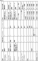
- FIG. 4 is a diagram illustrating an example of the relationship between input information and commands.
- the command unit 62 receives a command from the operator 22. Is recognized as a command for causing the surgical camera 11 to zoom in on the subject corresponding to the position of the line of sight represented by the line of sight position information (hereinafter referred to as a zoom in photographing command).
- the command unit 62 determines that the command from the operator 22 It is recognized that this is a command (hereinafter referred to as a zoom-out shooting command) for causing the surgical camera 11 to perform zoom-out shooting around the subject corresponding to the position of the line of sight represented by the position information.
- the command unit 62 determines that the command from the operator 22 is the line-of-sight position information. Is recognized as a command (hereinafter referred to as a focus control command) for performing focus control of the surgical camera 11 so as to focus on the subject corresponding to the position of the line of sight represented by.
- zoom-in imaging command the zoom-out imaging command
- focus control command are commands related to the imaging control of the surgical camera 11
- types of these commands are classified as “imaging control”.
- the surgeon 22 can input the contents of the imaging control with sound suitable for command input, and can input the position necessary for the imaging control with a line of sight suitable for position input. Therefore, the surgeon 22 can easily give a command related to imaging control.
- the voice recognition result of the input information is “pivot”
- the line-of-sight position information represents the position in the screen of the display 14
- the line-of-sight position information does not change with time, and the movement of the head 22A can be moved.
- the command unit 62 causes the camera arm so that the command from the operator 22 pivots the surgical camera 11 according to the movement of the head 22A. 12 (hereinafter referred to as a pivot operation command).
- the voice recognition result is “slide”
- the movement of the head 22A is rotation
- the line-of-sight position information represents the position in the screen of the display 14
- the temporal change in the position represented by the line-of-sight position information When the direction is the same as the rotation direction of the head 22A, and when the operation information indicates pressing of the foot switch 20, the command unit 62 determines that the command from the operator 22 is operated according to the position of the line of sight. It is recognized that this is a command for controlling the camera arm 12 so that the camera 11 slides (hereinafter referred to as a slide motion command).
- pivot operation command and the slide operation command are commands related to drive control of the camera arm 12, the types of these commands are classified as “camera arm control”.
- the command unit 62 uses the “operation control” or “camera arm control” type as the command from the operator 22. Does not recognize commands to change images.
- the command unit 62 determines that it is a misrecognition, and does not recognize that the command from the operator 22 is a zoom-in shooting command (zoom-out shooting command, focus control command).
- the command unit 62 Is determined to be erroneous recognition, and does not recognize that the command from the operator 22 is a zoom-in shooting command (zoom-out shooting command, focus control command).
- the voice recognition result of the input information is “focus”, the line-of-sight position information represents the position in the screen, the movement of the head 22A is movement, and the operation information represents the pressing of the foot switch 20.
- the command unit 62 determines that the recognition is erroneously recognized and does not recognize that the command from the operator 22 is a pivot operation command.
- the line-of-sight position information represents the position in the screen, the movement of the head 22A is moving, and the line-of-sight position information does not change with time Even so, when the operation information does not indicate that the foot switch 20 is pressed, the command unit 62 determines that the command is erroneously recognized, and does not recognize that the command from the operator 22 is a pivot motion command.
- the number of input information in the command recognition condition of the type “camera arm control” is larger than 2, which is the number of input information in the command recognition condition of the type “imaging control”. It is three.
- a condition that the operation information represents pressing of the foot switch 20 may be added as a recognition condition for the command of the type “shooting control”, and the number of input information in the recognition condition may be three.
- the command unit 62 recognizes that the command from the operator 22 is a menu display command. . Since the menu display command is a command related to GUI display control such as a menu button of the image processing unit 66 (display control device), the type of the menu display command is classified as “menu display control”.
- the command unit 62 receives a command from the operator 22 on the display 14. It is recognized that this is an annotation display command for displaying a mark as an annotation at a position corresponding to the line of sight of the operator 22 in the screen. Since the annotation display command is a command related to the annotation display control of the image processing unit 66, the type of the annotation display command is classified as “annotation display control”.
- the command unit 62 instructs the operation mode to be the hands-free operation mode. Recognize that it is a command to set the mode (hereinafter referred to as hands-free mode command).
- the command unit 62 instructs the operation mode in the normal state to be the manual mode. It is recognized that this is a command to be set to (hereinafter referred to as manual mode command).
- the command unit 62 Recognize the command.
- the command unit 62 recognizes that the command from the operator 22 is a manual mode command in a normal state.
- the command unit 62 is manually operated when the command from the operator 22 is in a normal state. Recognize that it is a mode command.
- the command unit 62 is a manual mode command in an emergency state. Recognize that there is.
- the emergency state is a state in which the hands-free mode must be stopped urgently due to a malfunction or the like.
- the recognition condition of the manual mode command in the emergency state is a condition other than the recognition condition of other commands
- the gesture of the surgeon 22 is other than a pre-registered gesture or the sound volume is larger than a predetermined value. It may be other than the conditions.
- the operator 22 uses the input content necessary for the recognition of the command by using sound, volume, line of sight, movement and direction of the head 22A, gesture, or operation of the foot foot switch 20 suitable for the type of the input content.
- any recognition condition may be used.
- there is one type of input information for non-contact input in the command recognition conditions whose types are “menu display control”, “annotation display control”, and “mode control”. However, there may be a plurality.
- the command recognized by the command unit 62 may be any command as long as it is a command for controlling each unit of the surgical system 10.
- the command unit 62 may recognize a command for setting various parameters of the surgical camera 11.
- FIG. 5 is a diagram for explaining the execution of the pivot operation command by the control unit 65 of FIG.
- FIG. 5A is a diagram showing the head 22A and the display 14 viewed from the y direction
- FIG. 5B is a diagram showing the surgical camera 11 viewed from the direction between the z direction and the y direction. It is.
- the control unit 65 drives and controls the camera arm 12 to cause the surgical camera 11 to pivot by an amount corresponding to the movement amount of the head 22A in the x direction. Accordingly, as shown in FIG. 5B, the surgical camera 11 moves in the x direction by an amount corresponding to the movement amount of the head 22A without changing the distance from the center P.
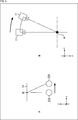
- FIG. 6 is a diagram for explaining the execution of the slide operation command by the control unit 65 of FIG.
- FIG. 6A is a diagram illustrating the head 22A and the display 14 viewed from the y direction
- FIG. 6B is a diagram illustrating the surgical camera 11 viewed from the z direction.
- the control unit 65 controls the drive of the camera arm 12 so that the subject corresponding to the position R ′ of the line of sight on the screen after the movement becomes the photographing center.
- the camera 11 is slid in the x direction.
- the center P of the surgical field that is the subject of imaging by the surgical camera 11 moves in the x direction.
- control unit 65 may control the speed of the sliding operation in accordance with the rotational speed of the head 22A.
- FIG. 7 is a diagram illustrating an example of the state of the operator 22 estimated by the state estimation unit 64 of FIG.
- the state estimation unit 64 estimates the state of the operator 22 as an out-of-procedure operation state, an overhead view state, a gaze state, or an observation state.
- the out-of-procedure operation state is a state in which the operator 22 is performing an operation other than the procedure (for example, checking the hand holding the forceps or the like, grasping the situation of surrounding assistants or staff). It is assumed that the surgeon 22 is not facing the display 14 in the non-procedure operation state. Therefore, there is no need to change the operative field image. Therefore, when it is estimated that the state of the operator 22 is an operation state outside the procedure, the command unit 62 changes the operation mode, and commands from the operator 22 other than the command whose type is “mode control” The command is limited to a command that does not change the operative field image and the type is “menu display control”.
- the bird's-eye view is a state in which the surgeon 22 looks down on the surgical field to check for tissue damage or bleeding.
- the surgeon 22 may want to indicate a predetermined position in the operative field image to surrounding assistants or staff. Accordingly, when it is estimated that the state of the surgeon 22 is a bird's-eye view state, a command from the surgeon 22 other than a command whose type is “mode control”, a command whose type is “menu display control”, and an operation The command is superposed on the field image and the type is “annotation display control”.
- the gaze state is a state in which the operator 22 is performing a procedure while gazing at one point in the operative field image.
- the line of sight of the operator 22 is within the screen of the display 14, and the movement of the line of sight of the operator 22 is small, but it is assumed that the operator 22 is moving.
- the operator 22 does not need to change the contents of the operative field image, but needs to see the operative field image photographed under photographing conditions suitable for the procedure.
- the command unit 62 receives a command from the operator 22 other than the command whose type is “mode control”, the type “menu display control”, and It is limited to a command that is “annotation display control” and a command that changes the shooting condition and the type is “shooting control”.
- the observation state is a state in which the operator 22 suspends the procedure and observes the patient 21 to perform an important treatment.
- the line of sight of the operator 22 is in the screen of the display 14 and the movement of the line of sight of the operator 22 and the movement of the operator 22 are small.
- the surgeon 22 needs to observe the operative field from many directions, and thus needs to change the contents of the operative field image.
- the command unit 62 permits all commands from the operator 22 other than the command whose type is “mode control”. That is, the command unit 62 changes the position of the surgical camera 11 as well as the commands of the types “menu display control”, “annotation display control”, and “imaging control”, and the type is “camera arm control”. The directive which is is also permitted.
- the necessity of changing the operative field image is, in order from the lowest, the non-procedure operation state, the overhead view state, the gaze state, and the observation state.
- the types are “menu display control”, “annotation display control”, “imaging control”, “camera arm”, respectively. Only commands that are "control” may be permitted.
- FIG. 8 is a diagram illustrating a method for estimating the state of the operator 22 in the state estimation unit 64 of FIG.
- the state estimation unit 64 determines whether or not the operator 22 is facing the display 14 based on the direction of the head 22A or the line-of-sight position information in the input information.
- the state estimation unit 64 determines that the surgeon 22 is facing the display 14 when the direction of the head 22A is the direction toward the display 14, and is not the direction toward the display 14. , It is determined that the display 14 is not directly facing.
- the state estimation unit 64 determines that it is facing the display 14, and when it is outside the screen, the state estimation unit 64 determines that it is not facing the display 14. To do.
- the state estimation unit 64 determines that the movement amount of the line of sight is large when the movement amount is larger than the predetermined value based on the movement amount within the predetermined time of the position represented by the visual line position information, and is less than the predetermined value. In this case, it is determined that the movement amount of the line of sight is small.
- the state estimation unit 64 determines that the surgeon 22 is moving when the amount of movement of the head 22A within a predetermined time is greater than a predetermined value, and is below the predetermined value. If there is, it is determined that the operator 22 is not moving.
- the recognizing unit 61 recognizes the movement of the part other than the head 22A of the operator 22, and the state estimation unit 64 determines the movement of the operator 22 based on the movement of the part other than the head 22A of the operator 22. It may be determined whether or not there is. In this case, the recognizing unit 61 determines that the operator 22 is moving when the amount of movement of the part other than the head 22A of the operator 22 within a predetermined time is greater than a predetermined value, and is less than or equal to the predetermined value. It is determined that the surgeon 22 is not moving.
- the state estimation unit 64 determines that the operator 22 is not facing the display 14, the state estimation unit 64 estimates the state of the operator 22 as an out-of-procedure operation.
- the type of command from the permitted operator 22 other than “mode control” is “menu display control”.
- the state estimation unit 64 estimates the state of the operator 22 as an overhead view state when it is determined that the operator 22 is directly facing the display 14 and the amount of movement of the line of sight is large.
- the permitted command types other than “mode control” are “menu display control” and “annotation display control”.
- the state estimation unit 64 determines that the operator 22 is directly facing the display 14, determines that the amount of movement of the line of sight is small, and determines that the operator 22 is moving, the state of the operator 22 Is estimated as a gaze state.
- the permitted command types other than “mode control” are “menu display control”, “annotation display control”, and “imaging control”.
- the state estimation unit 64 determines that the operator 22 is directly facing the display 14, determines that the amount of movement of the line of sight is small, and determines that the operator 22 is not moving. Is estimated as an observation state.
- the permitted command types other than “mode control” are “menu display control”, “annotation display control”, “imaging control”, and “camera arm control”.
- the state estimation unit 64 The state of the person 22 may be determined as a gaze state.
- FIG. 9 is a flowchart for explaining a control process of the control device 15 of the surgical system 10 of FIG. This control process is started, for example, when the power of the control device 15 is turned on.
- the mode setting unit 63 sets the operation mode to the manual mode and supplies it to the state estimation unit 64.
- the recognition unit 61 recognizes input information.
- the recognition unit 61 supplies the voice recognition result, volume, gesture, and operation information of the input information to the command unit 62.
- the recognizing unit 61 supplies the line-of-sight position information to the command unit 62, the state estimating unit 64, and the image processing unit 66.
- the recognition unit 61 supplies the movement and direction of the head 22A to the command unit 62 and the state estimation unit 64 as input information.
- step S ⁇ b> 13 the command unit 62 recognizes the command from the operator 22 based on the input information supplied from the recognition unit 61.
- step S ⁇ b> 14 the command unit 62 determines whether or not the recognized command type is “mode control”.
- step S14 If it is determined that the command type recognized in step S14 is “mode control”, the command unit 62 notifies the mode setting unit 63 of the command, and the process proceeds to step S15.
- step S ⁇ b> 15 the mode setting unit 63 changes the operation mode in accordance with the command supplied from the command unit 62.
- the mode setting unit 63 supplies the changed operation mode to the state estimation unit 64, and the process proceeds to step S16.
- step S14 determines whether the type of command recognized in step S14 is “mode control”. If it is determined that the type of command recognized in step S14 is not “mode control”, the process proceeds to step S16.
- step S16 the state estimation unit 64 determines whether or not the operation mode supplied from the mode setting unit 63 is the hands-free mode. If it is determined in step S16 that the operation mode is the hands-free mode, the process proceeds to step S17.
- step S ⁇ b> 17 the control device 15 performs state estimation processing for estimating the state of the operator 22 based on the input information supplied from the recognition unit 61. Details of this state estimation processing will be described with reference to FIG.
- step S18 the command unit 62 determines whether or not the type of command from the operator 22 other than the command of the type “mode control” recognized in step S13 is permitted. If it is determined in step S18 that the command is permitted, the command unit 62 supplies the command to the control unit 65.
- step S19 the control part 65 performs the instruction
- step S16 when it is determined in step S16 that the operation mode is not the hands-free mode, or in step S18, it is determined that the type of command from the operator 22 other than the command whose type is “mode control” is not permitted. If so, the process proceeds to step S20.
- step S20 the control device 15 determines whether or not to turn off the power of the control device 15, for example, whether or not the operator 22 has instructed to turn off the power of the control device 15. If it is determined in step S20 that the power of the control device 15 is not turned off, the process returns to step S12, and the processes of steps S12 to S20 are repeated.
- step S20 if it is determined in step S20 that the control device 15 is to be powered off, the process ends.
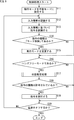
- FIG. 10 is a flowchart for explaining the details of the state estimation process in step S17 of FIG.
- the state estimation unit 64 determines whether or not the operator 22 is facing the display 14 based on the direction of the head 22A or the line-of-sight position information in the input information.
- step S42 the state estimation unit 64 estimates the state of the operator 22 as an out-of-procedure operation state and notifies the command unit 62 of the state. .
- step S43 the command unit 62 sets the type of command from the permitted operator 22 other than “mode control” to “menu display control”. And a process returns to step S17 of FIG. 9, and the process of step S18 is performed.
- step S44 the state estimation unit 64, based on the movement amount within a predetermined time of the position represented by the line-of-sight position information, It is determined whether or not the amount of eye movement is large.
- step S45 the state estimation unit 64 estimates the state of the operator 22 as an overhead view state and notifies the command unit 62 of it.
- step S46 the command unit 62 sets the types of commands from the permitted operator 22 other than “mode control” as “menu display control” and “annotation display control”. And a process returns to step S17 of FIG. 9, and the process of step S18 is performed.
- step S47 the state estimation unit 64 determines whether the operator 22 is moving based on the movement of the head 22A.
- step S48 the state estimation unit 64 estimates the state of the operator 22 as a gaze state and notifies the command unit 62 of the state.
- step S49 the command unit 62 sets the types of commands from the permitted operator 22 other than “mode control” to “menu display control”, “annotation display control”, and “imaging control”. And a process returns to step S17 of FIG. 9, and the process of step S18 is performed.
- step S50 the state estimation unit 64 estimates the state of the operator 22 as an observation state and notifies the instruction unit 62 of the state.
- step S51 the command unit 62 sets the types of commands from the permitted surgeon 22 as “menu display control”, “annotation display control”, “imaging control”, and “camera arm control”. And a process returns to step S17 of FIG. 9, and the process of step S18 is performed.
- the surgery system 10 controls the surgical camera 11, the camera arm 12, or the image processing unit 66 based on a combination of a plurality of types of non-contact inputs. Therefore, the surgeon 22 controls the surgical camera 11, the camera arm 12, and the image processing unit 66 simply and intuitively, for example, by performing non-contact input suitable for each type of input content. Can do. That is, the surgery system 10 can realize NUI (Natural User Interface). As a result, the burden on the operator 22 is reduced.
- NUI Natural User Interface
- the input recognition correct answer rate is improved and the safety of the operation is improved.
- the operation system 10 can perform input by non-contact or contact of the leg 22B, the operator 22 can perform input even when both hands are used in a technique. As a result, it is not necessary to interrupt the procedure for input compared to the case where the operator 22 performs input by hand, so that the operation time can be shortened. Further, compared to the case where a person other than the operator 22 operates, the control as intended by the operator 22 can be performed, so that the burden on the operator 22 is reduced.
- the surgery system 10 realizes fail-safe by restricting the execution of commands from the surgeon 22 according to the condition of the surgeon 22, and the surgeon 22 does not intend due to erroneous recognition of the command from the surgeon 22. Control can be prevented. Therefore, the safety of the operation is improved.
- the operation system 10 can change the operation mode from the hands-free mode to the manual mode, when the operator 22 performs unintended control due to erroneous recognition of the command from the operator 22, the control is performed. Can be stopped.
- FIG. 11 is a block diagram illustrating a configuration example of the second embodiment of the surgery system to which the present disclosure is applied.
- the configuration of the surgical system 100 in FIG. 11 is that the display 101 and the control device 102 are provided instead of the display 14 and the control device 15, and that the glasses 17 and the markers 19 are not provided. Different from 10 configurations.
- the distance between the display 101 and the surgeon 22 is shorter than the distance between the display 14 and the surgeon 22, and the surgeon 22 does not wear the glasses 17 and puts on the display 101 with the naked eye.
- the displayed surgical field image is recognized as a 3D image.
- the display 101 of the surgical system 100 is a 3D display having a relatively small screen and is relatively close to the operator 22 (in the example of FIG. 11, close to the operator 22 on the operating table 16). Position).
- the display 101 displays an operative field image transmitted from the control device 102.
- An operation recognition camera 13 is disposed on the display 101.
- control device 102 Since the control device 102 is the same as the control device 15 except for the method of recognizing the movement and direction of the line of sight and the head 22A, only the recognition method will be described below.
- the control device 102 recognizes the movement and direction of the head 22 ⁇ / b> A by detecting the position of the head 22 ⁇ / b> A in the operator image transmitted from the motion recognition camera 13.
- the control device 102 detects the direction of the line of sight of the operator 22 from the operator image, and recognizes the position of the line of sight on the screen of the display 14 based on the direction.
- the surgeon 22 since the surgeon 22 does not wear the glasses 17, gaze detection is performed using the surgeon image taken by the motion recognition camera 13, but the surgeon 22 Eyeglasses equipped with a detection device may be worn so that the line-of-sight detection device performs line-of-sight detection.
- the movement and direction of the head 22A are detected from the surgeon image.
- the surgeon 22 wears the marker 19 and operates.
- the movement and direction of the head 22A may be detected from the position of the marker 19 in the person image.
- the display 101 may be disposed at a position relatively far from the operator 22.
- the display 101 may be a 3D display that allows the operator 22 to recognize 3D images by using the 3D polarized glasses, and the operator 22 may wear the 3D polarized glasses.
- the above-described series of processing of the control device 15 (102) can be executed by hardware or can be executed by software.
- a program constituting the software is installed in the computer.
- the computer includes, for example, a general-purpose personal computer capable of executing various functions by installing various programs by installing a computer incorporated in dedicated hardware.
- FIG. 12 is a block diagram showing an example of the hardware configuration of a computer that executes the above-described series of processing by a program.
- a CPU Central Processing Unit
- ROM Read Only Memory
- RAM Random Access Memory
- An input / output interface 205 is further connected to the bus 204.
- An input unit 206, an output unit 207, a storage unit 208, a communication unit 209, and a drive 210 are connected to the input / output interface 205.
- the input unit 206 includes a keyboard, a mouse, a microphone, and the like.
- the output unit 207 includes a display, a speaker, and the like.
- the storage unit 208 includes a hard disk, a nonvolatile memory, and the like.
- the communication unit 209 includes a network interface and the like.
- the drive 210 drives a removable medium 211 such as a magnetic disk, an optical disk, a magneto-optical disk, or a semiconductor memory.
- the CPU 201 loads the program stored in the storage unit 208 to the RAM 203 via the input / output interface 205 and the bus 204 and executes the program. A series of processing is performed.
- the program executed by the computer 200 can be provided by being recorded in, for example, a removable medium 211 such as a package medium.
- the program can be provided via a wired or wireless transmission medium such as a local area network, the Internet, or digital satellite broadcasting.
- the program can be installed in the storage unit 208 via the input / output interface 205 by attaching the removable medium 211 to the drive 210.
- the program can be received by the communication unit 209 via a wired or wireless transmission medium and installed in the storage unit 208.
- the program can be installed in the ROM 202 or the storage unit 208 in advance.
- the program executed by the computer 200 may be a program that is processed in time series in the order described in this specification, or a necessary timing such as in parallel or when a call is made. It may be a program in which processing is performed.
- the system means a set of a plurality of components (devices, modules (parts), etc.), and it does not matter whether all the components are in the same housing. Accordingly, a plurality of devices housed in separate housings and connected via a network and a single device housing a plurality of modules in one housing are all systems. .
- the control device 15 (102) performs control based on a combination of a plurality of types of non-contact inputs, and performs control according to the state of the operator 22.
- the safety of the surgery is improved by both limiting, the safety of the surgery may be improved by only one of them.
- control target by the control device 15 (102) may be any device as long as it is a surgical device.
- control device 15 (102) can control a surgical imaging apparatus such as an endoscope or a video microscope.
- the zoom control may be performed by processing the surgical field image in the image processing unit 66 instead of being performed by the imaging control of the surgical camera 11.
- the image processing unit 66 enlarges the surgical field image transmitted from the surgical camera 11 in response to the zoom-in photographing command, thereby zooming in on the subject corresponding to the position of the line of sight. Performs electronic zoom to generate images from operative field images. Similarly, the image processing unit 66 reduces the operative field image transmitted from the surgical camera 11 in response to the zoom-out shooting command, and is zoomed out with the subject corresponding to the position of the line of sight as the center. A zoom-out image is generated from the operative field image. At this time, the image processing unit 66 may superimpose a marker at a position corresponding to the line of sight in the zoom-in image or the zoom-out image based on the line-of-sight position information.
- the annotation display may be always performed.
- the non-contact input is not limited to the voice of the operator 22, the line of sight, the movement and direction of the head 22A, and the gesture.
- the movement or posture of the operator 22 other than the head 22A may be used.
- the means for accepting non-contact input may be wearable such as glasses 17 and microphone 18 or may not be wearable.
- the control device 15 (102) estimates the state of the operator 22 even when the operation mode is the manual mode, and the operation camera 11, the camera arm 12, and the image processing unit 66 according to the state. You may make it restrict
- this indication can also take the following structures.
- a state estimation unit that estimates the state of the user based on at least one non-contact input from the user recognized by the first non-contact input recognition unit;
- a restriction unit that restricts control of the surgical device based on at least one non-contact input from the user recognized by the second non-contact input recognition unit according to the state estimated by the state estimation unit.
- a surgical control device comprising: (2) The operation control device according to (1), wherein the non-contact input is an input of the voice, line of sight, movement, or gesture of the user. (3) The control is based on at least one non-contact input from the user recognized by the second non-contact input recognition unit and an input by contact from the user recognized by the contact input recognition unit.
- the surgical control device according to (1) or (2) configured to be performed.
- the state estimation unit is configured to estimate the state of the user as an out-of-procedure operation state, an overhead view state, a gaze state, or an observation state.
- the surgical operation according to any one of (1) to (3), Control device.
- the control of the surgical device includes menu display control of the display control device, annotation display control of the display control device, photographing control of the surgical photographing device for photographing a surgical field image, or driving of an arm holding the surgical photographing device.
- the surgical control apparatus according to (4) configured to be controlled.
- the restriction unit is configured to restrict the control of the surgical device to the menu display control of the display control device when the state estimation unit estimates that the user's state is an out-of-procedure operation state.
- the surgical control apparatus according to (5) above.
- the restriction unit is configured to restrict the control of the surgical device to the annotation display control of the display control device when the state estimation unit estimates that the user's state is an overhead view state.
- the surgical control apparatus according to 5) or (6).
- the limiting unit is configured to limit the control of the surgical apparatus to the imaging control of the surgical imaging apparatus when the state estimating unit estimates that the user's state is a gaze state.
- the surgical control apparatus according to any one of 5) to (7).
- the limiting unit is configured to limit the control of the surgical device to the drive control of the arm when the state estimating unit estimates that the state of the user is an observation state.
- the surgical control apparatus according to any one of (8).
- a mode setting unit that sets an operation mode of the surgical control device based on at least one type of non-contact input from the user recognized by the second non-contact input recognition unit (1)
- the operation control apparatus in any one of thru
- the state estimation unit is configured to estimate the state when the operation mode is a mode for controlling the surgical device based on at least one non-contact input from the user.
- the surgical control apparatus according to 10).
- the surgical control device A state estimation step of estimating the state of the user based on at least one kind of non-contact input from the user recognized by the first non-contact input recognition unit; The control of the surgical apparatus based on at least one non-contact input from the user recognized by the second non-contact input recognition unit is limited according to the state estimated by the processing of the state estimation step.
- a surgical control method comprising: a limiting step. (13)
- Computer A state estimation unit that estimates the state of the user based on at least one non-contact input from the user recognized by the first non-contact input recognition unit;
- a restriction unit that restricts control of the surgical device based on at least one non-contact input from the user recognized by the second non-contact input recognition unit according to the state estimated by the state estimation unit.
Landscapes
- Engineering & Computer Science (AREA)
- Health & Medical Sciences (AREA)
- Surgery (AREA)
- Life Sciences & Earth Sciences (AREA)
- Molecular Biology (AREA)
- Public Health (AREA)
- Nuclear Medicine, Radiotherapy & Molecular Imaging (AREA)
- Biomedical Technology (AREA)
- Heart & Thoracic Surgery (AREA)
- Medical Informatics (AREA)
- Veterinary Medicine (AREA)
- Animal Behavior & Ethology (AREA)
- General Health & Medical Sciences (AREA)
- General Engineering & Computer Science (AREA)
- Theoretical Computer Science (AREA)
- Human Computer Interaction (AREA)
- Robotics (AREA)
- Oral & Maxillofacial Surgery (AREA)
- Pathology (AREA)
- Physics & Mathematics (AREA)
- General Physics & Mathematics (AREA)
- User Interface Of Digital Computer (AREA)
- Manipulator (AREA)
Abstract
本発明は、非接触の入力により手術用装置を制御する場合に手術用装置の誤動作を防止することができるようにする手術用制御装置、手術用制御方法、およびプログラムに関する。状態推定部(64)は、認識部(61)により認識された術者からの少なくとも1種類の非接触の入力に基づいて、術者の状態を推定する。指令部(62)は、状態推定部(64)により推定された状態に応じて、認識部(61)により認識された術者からの少なくとも1種類の非接触の入力に基づく術用カメラ(11)、カメラアーム(12)、または画像処理部(66)の制御を制限する。本発明は、例えば、術用カメラ(11)、カメラアーム(12)、動作認識用カメラ(13)、ディスプレイ(14)、制御装置(15)、眼鏡(17)、マイクロフォン(18)、マーカ、フットスイッチ(20)等を有し、画像を参照した処置を可能にする手術システム等に適用することができる。
Description
本開示は、手術用制御装置、手術用制御方法、およびプログラムに関し、特に、非接触の入力により手術用装置を制御する場合に手術用装置の誤動作を防止することができるようにした手術用制御装置、手術用制御方法、およびプログラムに関する。
音声、ジェスチャ、視線などの非接触の入力により、手術用装置を制御する手術システムが考案されている(例えば、特許文献1参照)。このような手術システムでは、滅菌対策が必須である術者が、操作ボタン等に接触することなく手術用装置を制御することができる。
しかしながら、非接触の入力は、接触による入力に比べて、入力が誤認識される可能性があり、手術用装置が誤動作する場合がある。手術システムにおいては、手術用装置の誤動作が患者の生命を左右するため、手術用装置の誤動作を防止することは必須である。
従って、非接触の入力により手術用装置を制御する場合にフェールセーフを実現し、手術用装置の誤動作を防止することが求められている。
本開示は、このような状況に鑑みてなされたものであり、非接触の入力により手術用装置を制御する場合に手術用装置の誤動作を防止することができるようにするものである。
本開示の一側面の手術用制御装置は、第1の非接触入力認識部により認識されたユーザからの少なくとも1種類の非接触の入力に基づいて、前記ユーザの状態を推定する状態推定部と、前記状態推定部により推定された前記状態に応じて、第2の非接触入力認識部により認識された前記ユーザからの少なくとも1種類の非接触の入力に基づく手術用装置の制御を制限する制限部とを備える手術用制御装置である。
本開示の一側面の手術用制御方法およびプログラムは、本開示の一側面の手術用制御装置に対応する。
本開示の一側面においては、第1の非接触入力認識部により認識されたユーザからの少なくとも1種類の非接触の入力に基づいて、前記ユーザの状態が推定され、推定された前記状態に応じて、第2の非接触入力認識部により認識された前記ユーザからの少なくとも1種類の非接触の入力に基づく手術用装置の制御が制限される。
本開示の一側面によれば、手術用装置を制御することができる。また、本開示の一側面によれば、非接触の入力により手術用装置を制御する場合に手術用装置の誤動作を防止することができる。
なお、ここに記載された効果は必ずしも限定されるものではなく、本開示中に記載されたいずれかの効果であってもよい。
以下、本開示を実施するための形態(以下、実施の形態という)について説明する。なお、説明は以下の順序で行う。
1.第1実施の形態:手術システム(図1乃至図10)
2.第2実施の形態:手術システム(図11)
3.第3実施の形態:コンピュータ(図12)
1.第1実施の形態:手術システム(図1乃至図10)
2.第2実施の形態:手術システム(図11)
3.第3実施の形態:コンピュータ(図12)
<第1実施の形態>
(手術システムの第1実施の形態の構成例)
図1は、本開示を適用した手術システムの第1実施の形態の構成例を示すブロック図である。
(手術システムの第1実施の形態の構成例)
図1は、本開示を適用した手術システムの第1実施の形態の構成例を示すブロック図である。
手術システム10は、術用カメラ11、カメラアーム12、動作認識用カメラ13、ディスプレイ14、制御装置15、手術台16、眼鏡17、マイクロフォン18、マーカ19、およびフットスイッチ20により構成される。手術システム10は、手術室等に配置され、術用カメラ11により撮影される画像を参照した外科手術等の処置を可能にする。
具体的には、手術システム10の術用カメラ11(手術用撮影装置)は、カメラアーム12により保持された3Dカメラ等のモダリティ機器である。術用カメラ11は、手術台16に横たわる患者21の術野等を撮影し、その結果得られる3D画像を術野画像として制御装置15に送信する。カメラアーム12は、術用カメラ11を保持し、術用カメラ11の位置や角度を制御する。
動作認識用カメラ13は、例えば2Dカメラであり、ディスプレイ14の上に配置される。動作認識用カメラ13は、眼鏡17、マイクロフォン18、およびマーカ19を頭部22Aに装着した術者22を撮影する。動作認識用カメラ13は、撮影の結果得られる2D画像を術者画像として制御装置15に送信する。
ディスプレイ14は、比較的大きい画面を有する3Dディスプレイであり、術者22から比較的離れた位置(図1の例では、手術台16を挟んで術者22と対向する位置)に配置される。制御装置15から送信されてくる術野画像等を表示する。
制御装置15は、動作モードを、手動モードまたはハンズフリーモードに設定する。手動モードとは、術者22の手による入力(例えば、カメラアーム12への加力や、各部に設けられた図示せぬ操作ボタン等の操作)に基づいて手術システム10の制御を行うモードである。ハンズフリーモードとは、術者22の手によらない、音声、視線、頭部22Aの動きや方向、ジェスチャなどの非接触の入力やフットフットスイッチ20への脚部22Bの接触による入力に基づいて、手術システム10の制御を行うモードである。
また、制御装置15は、動作認識用カメラ13から送信されてくる術者画像を受信し、術者画像内の術者22の頭部22Aに装着されたマーカ19の位置を検出することにより、頭部22Aの動きの検出(ヘッドトラッキング)や頭部22Aの方向の認識を行う。さらに、制御装置15は、術者画像から術者22のジェスチャを認識する。
制御装置15は、眼鏡17から送信されてくる術者22の視線の方向を表す情報を受信し、その情報と頭部22Aの位置および方向とに基づいてディスプレイ14の画面上の視線の位置を認識する。制御装置15は、マイクロフォン18から送信されてくる音声を受信し、その音声に対して音声認識を行う。制御装置15は、フットスイッチ20から送信されてくるフットスイッチ20に対する操作を表す操作信号を受信し、その操作信号に基づいてフットスイッチ20に対する操作の内容を認識する。
さらに、動作モードがハンズフリーモードである場合、制御装置15は、頭部22Aの動きや方向、術者22のジェスチャ、ディスプレイ14の画面上の視線の位置を表す視線位置情報、音声認識結果、音量、およびフットスイッチ20に対する操作の内容を表す操作情報を入力情報とする。制御装置15は、入力情報に基づいて術者22からの指令および術者22の状態を認識する。
制御装置15は、術者22の状態に応じて、術者22からの指令を許可する。制御装置15は、許可された指令に応じて、術用カメラ11の撮影を制御したり、カメラアーム12の駆動を制御したり、ディスプレイ14の表示を制御したり、動作モードを変更したりする。
眼鏡17は、術者22の頭部22Aに装着され、3D偏光眼鏡と視線検出デバイスにより構成される。術者22は、眼鏡17の3D偏光眼鏡を介してディスプレイ14を見ることにより、ディスプレイ14に表示される術野画像を3D画像として認識することができる。
また、術者22は、眼鏡17を介して周囲を見ることにより、眼鏡17に視線を入力する。眼鏡17の視線検出デバイスは、術者22の視線を検出し、視線の方向を表す情報を制御装置15に送信する。
マイクロフォン18は、術者22の頭部22Aに装着される。マイクロフォンは、術者22の音声等を含む周囲の音声を取得し、制御装置15に送信する。マーカ19は、術者22の頭部22Aに装着される。
フットスイッチ20は、術者22の周囲に配置され、術者22の脚部22Bの接触により操作される。フットスイッチ20は、術者22からの脚部22Bの操作を表す操作信号を制御装置15に送信する。
以上のように構成される手術システム10では、術者22は、患者21を手術台16の上に横たわらせ、ディスプレイ14に表示される術野画像等を、眼鏡17を介して見ながら、外科手術等の処置を行う。
また、術者22は、動作モード、術用カメラ11の撮影条件、術用カメラ11の位置や角度、ディスプレイ14の表示等を変更する場合、非接触の入力または足の接触による入力を行う。従って、術者22は、図示せぬ術具を把持した状態で入力を行うことができる。また、術者22は、入力を行うたびに、滅菌処理を行う必要がない。
なお、視線検出方法、術者22の頭部22Aの動きや方向、および、ジェスチャの検出方法、音声の取得方法としては、任意の方法を採用することができる。例えば、視線検出デバイスやマイクロフォン18は、ウェアラブルデバイスでなくてもよい。
本明細書では、ディスプレイ14の水平方向をx方向といい、垂直方向をy方向といい、ディスプレイ14の画面に対して垂直な方向をz方向という。
(術用カメラの駆動の説明)
図2は、図1のカメラアーム12による術用カメラ11の駆動を説明する図である。
図2は、図1のカメラアーム12による術用カメラ11の駆動を説明する図である。
図2のAに示すように、カメラアーム12は、術用カメラ11に、撮影中心を変更せずに撮影角度を変更するピボット動作を行わせることができる。具体的には、カメラアーム12は、術用カメラ11の撮影対象である術野の中心Pからの距離が常に一定になるように、術用カメラ11を移動させることができる。これにより、術用カメラ11は、術野の中心Pが同一であり、撮影角度が異なる術野画像を撮影することができる。
また、図2のBに示すように、カメラアーム12は、術用カメラ11に、撮影中心をx方向に移動させるx方向へのスライド動作を行わせることができる。具体的には、カメラアーム12は、術用カメラ11をx方向に移動させることができる。これにより、術用カメラ11は、撮影対象である術野の中心Pをx方向に移動させることができる。
さらに、図示は省略するが、カメラアーム12は、術用カメラ11にy方向やz方向へのスライド動作を行わせることができる。術用カメラ11がy方向へのスライド動作を行う場合、術用カメラ11は、撮影範囲を拡大または縮小することができる。また、術用カメラ11がz方向へのスライド動作を行う場合、術用カメラ11は、撮影対象である術野の中心Pをz方向に移動させることができる。
なお、本明細書では、術用カメラ11のスライド動作が、カメラアーム12による術用カメラ11の移動によって行われるものとするが、カメラアーム12による術用カメラ11の撮影角度の変更によって行われるようにしてもよい。
(制御装置の構成例)
図3は、図1の制御装置15の構成例を示すブロック図である。
図3は、図1の制御装置15の構成例を示すブロック図である。
図3の制御装置15は、認識部61、指令部62、モード設定部63、状態推定部64、制御部65、および画像処理部66により構成される。
制御装置15の認識部61は、音声認識部71、視線認識部72、頭部認識部73、ジェスチャ認識部74、および操作認識部75により構成される。
音声認識部71(非接触入力認識部)は、マイクロフォン18から送信されてくる音声に対して音声認識を行い、術者22(ユーザ)の非接触の入力として、発話を認識する。また、音声認識部71は、術者22の非接触の入力として、マイクロフォン18から送信されてくる音声の音量を認識する。音声認識部71は、音声認識結果である発話および音量を入力情報として指令部62に供給する。
視線認識部72(非接触入力認識部)は、眼鏡17から送信されてくる視線の方向を表す情報と、頭部認識部73により認識される頭部22Aの位置および方向とに基づいて、術者22の非接触の入力として、ディスプレイ14の画面上の視線の位置を認識する。視線認識部72は、その位置を表す視線位置情報を入力情報として指令部62、状態推定部64、および画像処理部66に供給する。
頭部認識部73(非接触入力認識部)は、動作認識用カメラ13から送信されてくる術者画像から術者画像内のマーカ19の位置を検出することにより、術者22からの非接触の入力として、術者22の頭部22Aの位置、動き、および方向を認識する。頭部認識部73は、頭部22Aの動きや方向を入力情報として指令部62と状態推定部64に供給する。また、頭部認識部73は、頭部22Aの位置および方向を視線認識部72に供給する。
ジェスチャ認識部74(非接触入力認識部)は、動作認識用カメラ13から送信されてくる術者画像から、術者22からの非接触の入力として、術者22のジェスチャの入力を認識する。ジェスチャ認識部74は、術者22のジェスチャを入力情報として指令部62に供給する。
操作認識部75(接触入力認識部)は、フットスイッチ20から送信されてくる操作信号を受信し、術者22からの接触による入力として、フットスイッチ20に対する操作の内容を認識する。操作認識部75は、その操作の内容を表す操作情報を入力情報として指令部62に供給する。
指令部62は、認識部61から供給される入力情報に基づいて、術者22からの指令を認識する。指令部62は、認識された指令が動作モードを変更する指令である場合、その指令をモード設定部63に通知する。
一方、術者22から認識された指令が動作モードを変更する指令ではない場合、指令部62(制限部)は、状態推定部64から供給される状態に応じて、術者22からの指令を制限する。即ち、指令部62は、状態推定部64から供給される状態に応じて、術者22からの所定の指令を許可する。指令部62は、許可された指令を制御部65に供給する。
モード設定部63は、指令部62から供給される指令に応じて、動作モードを手動モードまたはハンズフリーモードに設定する。モード設定部63は、設定された動作モードを状態推定部64に供給する。
状態推定部64は、モード設定部63から供給される動作モードがハンズフリーモードである場合、認識部61から供給される入力情報に基づいて術者22の状態を推定する。状態推定部64は、推定された状態を指令部62に通知する。
制御部65は、指令部62から供給される指令を実行する。具体的には、指令部62から供給される指令が、術用カメラ11の撮影制御に関する指令である場合、制御部65は、その指令に応じて術用カメラ11(手術用装置)の撮影制御を行う。
また、指令部62から供給される指令が、カメラアーム12の駆動制御に関する指令である場合、制御部65は、その指令に応じてカメラアーム12(手術用装置)の駆動制御を行う。また、指令部62から供給される指令が、ディスプレイ14の表示制御に関する指令である場合、制御部65は、その指令を画像処理部66に供給することにより画像処理部66(手術用装置)を制御する。
画像処理部66は、術用カメラ11から送信されてくる術野画像を処理する。具体的には、画像処理部66は、術用カメラ11から送信されてくる術野画像をそのままディスプレイ14に供給し、表示させる。
また、画像処理部66は、制御部65から供給される指令が、アノテーション表示指令である場合、視線認識部72から供給される視線位置情報に基づいて、術用カメラ11から送信されてくる術野画像内の術者22の視線に対応する位置にマーク(所定の画像)を重畳させる。そして、画像処理部66は、マークが重畳された術野画像をディスプレイ14に供給し、表示させる。
さらに、画像処理部66は、制御部65から供給される指令が、メニューボタンなどのGUI(Graphical User Interface)をディスプレイ14に表示させるメニュー表示指令である場合、術用カメラ11から送信されてくる術野画像にGUIの画像を重畳させる。画像処理部66は、GUIが重畳された術野画像をディスプレイ14に供給し、表示させる。
(入力情報と指令の関係の例)
図4は、入力情報と指令の関係の例を示す図である。
図4は、入力情報と指令の関係の例を示す図である。
図4に示すように、入力情報のうちの音声認識結果が「ズームイン」であり、かつ、視線位置情報がディスプレイ14の画面内の位置を表す場合、指令部62は、術者22からの指令が、視線位置情報が表す視線の位置に対応する被写体を中心に術用カメラ11にズームイン撮影させる指令(以下、ズームイン撮影指令という)であることを認識する。
同様に、入力情報のうちの音声認識結果が「ズームアウト」であり、かつ、視線位置情報がディスプレイ14の画面内の位置を表す場合、指令部62は、術者22からの指令が、視線位置情報が表す視線の位置に対応する被写体を中心に術用カメラ11にズームアウト撮影させる指令(以下、ズームアウト撮影指令という)であることを認識する。
また、入力情報のうちの音声認識結果が「フォーカス」であり、かつ、視線位置情報がディスプレイ14の画面内の位置を表す場合、指令部62は、術者22からの指令が、視線位置情報が表す視線の位置に対応する被写体で合焦するように術用カメラ11のフォーカス制御を行う指令(以下、フォーカス制御指令という)であることを認識する。
なお、ズームイン撮影指令、ズームアウト撮影指令、およびフォーカス制御指令は、術用カメラ11の撮影制御に関する指令であるため、これらの指令の種類は、「撮影制御」に分類される。
以上により、術者22は、コマンド入力に適している音声で撮影制御の内容を入力し、位置入力に適している視線で撮影制御に必要な位置を入力することができる。従って、術者22は、撮影制御に関する指令を容易に行うことができる。
また、入力情報のうちの音声認識結果が「ピボット」であり、視線位置情報がディスプレイ14の画面内の位置を表し、視線位置情報が時間的に変化せず、頭部22Aの動きが移動である場合、かつ、操作情報がフットスイッチ20の押下を表す場合、指令部62は、術者22からの指令が、頭部22Aの動きに応じて術用カメラ11がピボット動作するようにカメラアーム12を制御する指令(以下、ピボット動作指令という)であることを認識する。
入力情報のうちの音声認識結果が「スライド」であり、頭部22Aの動きが回転であり、視線位置情報がディスプレイ14の画面内の位置を表し、視線位置情報が表す位置の時間的変化の方向が、頭部22Aの回転方向と同一である場合、かつ、操作情報がフットスイッチ20の押下を表す場合、指令部62は、術者22からの指令が、視線の位置に応じて術用カメラ11がスライド動作するようにカメラアーム12を制御する指令(以下、スライド動作指令という)であることを認識する。
なお、ピボット動作指令およびスライド動作指令は、カメラアーム12の駆動制御に関する指令であるため、これらの指令の種類は、「カメラアーム制御」に分類される。
以上のように、2以上の入力情報の組み合わせが条件を満たしていない場合、指令部62は、術者22からの指令として、種類が「撮影制御」または「カメラアーム制御」である、術野画像を変更する指令を認識しない。
例えば、入力情報のうちの音声認識結果が「ズームイン」(「ズームアウト」、「フォーカス」)である場合であっても、視線位置情報が画面内の位置を表さない場合には、指令部62は、誤認識と判断し、術者22からの指令がズームイン撮影指令(ズームアウト撮影指令、フォーカス制御指令)であることを認識しない。
逆に、入力情報のうちの視線位置情報が画面内の位置を表す場合であっても、音声認識結果が「ズームイン」(「ズームアウト」、「フォーカス」)ではない場合には、指令部62は、誤認識と判断し、術者22からの指令がズームイン撮影指令(ズームアウト撮影指令、フォーカス制御指令)であることを認識しない。
入力情報のうちの音声認識結果が「フォーカス」であり、視線位置情報が画面内の位置を表し、頭部22Aの動きが移動であり、操作情報がフットスイッチ20の押下を表す場合であっても、視線位置情報が時間的に変化している場合、指令部62は、誤認識と判断し、術者22からの指令がピボット動作指令であることを認識しない。
また、入力情報のうちの音声認識結果が「フォーカス」であり、視線位置情報が画面内の位置を表し、頭部22Aの動きが移動であり、視線位置情報が時間的に変化していない場合であっても、操作情報がフットスイッチ20の押下を表さない場合、指令部62は、誤認識と判断し、術者22からの指令がピボット動作指令であることを認識しない。
従って、手術への影響が大きい、術野画像が変更される指令の認識正答率を向上させることができる。その結果、手術の安全性を向上させることができる。
また、種類が「カメラアーム制御」である、術野画像の内容を大きく変更する指令は、種類が「撮影制御」である指令に比べて、手術への影響が大きい。従って、図4の例では、種類が「カメラアーム制御」である指令の認識条件における入力情報の数が、種類が「撮影制御」である指令の認識条件における入力情報の数である2より大きい3になっている。
なお、種類が「撮影制御」である指令の認識条件として、操作情報がフットスイッチ20の押下を表す場合という条件を追加し、認識条件における入力情報の数を3つにしてもよい。
入力情報のうちの音声認識結果が「メニュー」であり、かつ、操作情報がフットスイッチ20の押下を表す場合、指令部62は、術者22からの指令がメニュー表示指令であることを認識する。なお、メニュー表示指令は、画像処理部66(表示制御装置)のメニューボタンなどのGUIの表示制御に関する指令であるため、メニュー表示指令の種類は、「メニュー表示制御」に分類される。
また、入力情報のうちの音声認識結果が「アノテーション」または「ポインタ」であり、かつ、操作情報がフットスイッチ20の押下を表す場合、指令部62は、術者22からの指令が、ディスプレイ14の画面内の術者22の視線に対応する位置にマークをアノテーションとして表示させるアノテーション表示指令であることを認識する。なお、アノテーション表示指令は、画像処理部66のアノテーションの表示制御に関する指令であるため、アノテーション表示指令の種類は、「アノテーション表示制御」に分類される。
さらに、入力情報のうちの音声認識結果が「ハンズフリー」であり、かつ、操作情報がフットスイッチ20の押下を表す場合、指令部62は、術者22からの指令が、動作モードをハンズフリーモードに設定させる指令(以下、ハンズフリーモード指令という)であることを認識する。
入力情報のうちの音声認識結果が「停止」であり、かつ、操作情報がフットスイッチ20の押下を表す場合、指令部62は、術者22からの指令が、通常状態における動作モードを手動モードに設定させる指令(以下、手動モード指令という)であることを認識する。
以上のように、術者22が、メニュー表示指令、アノテーション表示指令、または手動モード指令に関する発話をマイクロフォン18に入力し、フットスイッチ20を押下することにより決定操作を行うと、指令部62は、その指令を認識する。
また、入力情報のうちの操作情報がフットスイッチ20の長押しを表す場合、指令部62は、術者22からの指令が通常状態における手動モード指令であることを認識する。入力情報のうちの視線位置情報が表す位置がディスプレイ14の画面外であり、かつ、操作情報がフットスイッチ20の押下を表す場合、指令部62は、術者22からの指令が通常状態における手動モード指令であることを認識する。
さらに、入力情報のうちの術者22のジェスチャが予め登録されたジェスチャ以外である場合、または、入力情報のうちの音量が所定値より大きい場合、指令部62は、緊急状態における手動モード指令であることを認識する。緊急状態とは、誤動作などにより緊急にハンズフリーモードの停止が必要になった状態である。
なお、緊急状態における手動モード指令の認識条件は、他の指令の認識条件以外の条件であれば、術者22のジェスチャが予め登録されたジェスチャ以外である、または、音量が所定値より大きいという条件以外であってもよい。
ハンズフリーモード指令および手動モード指令は、制御装置15の動作モードの制御に関する指令であるため、これらの指令の種類は、「モード制御」に分類される。
なお、入力情報と指令の関係は、上述した図4の例に限定されない。
即ち、術者22が、指令の認識に必要な入力内容を、その入力内容の種類に適した音声や音量、視線、頭部22Aの動きや方向、ジェスチャ、またはフットフットスイッチ20の操作を用いて入力することができれば、認識条件はどのようなものであってもよい。例えば、図4の例では、種類が「メニュー表示制御」、「アノテーション表示制御」、および「モード制御」である指令の認識条件における非接触の入力の入力情報の種類は、1つであったが、複数であってもよい。
また、指令部62により認識される指令は、手術システム10の各部を制御する指令であれば、どのような指令であってもよい。例えば、指令部62は、術用カメラ11の各種のパラメータを設定する指令を認識するようにしてもよい。
(ピボット動作指令の実行の説明)
図5は、図3の制御部65によるピボット動作指令の実行を説明する図である。
図5は、図3の制御部65によるピボット動作指令の実行を説明する図である。
なお、図5のAは、y方向から見た頭部22Aとディスプレイ14を示す図であり、図5のBは、z方向とy方向の間の方向から見た術用カメラ11を示す図である。
図5のAに示すように、術者22が「ピボット」という音声を発し、術者22の視線がディスプレイ14の画面内の位置Rに存在するとき、術者22が、フットスイッチ20を押下しながら、画面上の視線の位置を動かさずに頭部22Aだけx方向に移動すると、指令部62は、ピボット動作指令を認識する。
制御部65は、指令部62からピボット動作指令が供給された場合、カメラアーム12を駆動制御し、術用カメラ11をx方向に頭部22Aの移動量に応じた量だけピボット動作させる。これにより、図5のBに示すように、術用カメラ11は、中心Pからの距離を変更させずに、x方向に頭部22Aの移動量に応じた量だけ移動する。
(スライド動作指令の実行の説明)
図6は、図3の制御部65によるスライド動作指令の実行を説明する図である。
図6は、図3の制御部65によるスライド動作指令の実行を説明する図である。
なお、図6のAは、y方向から見た頭部22Aとディスプレイ14を示す図であり、図6のBは、z方向から見た術用カメラ11を示す図である。
図6のAに示すように、術者22が「スライド」という音声を発し、術者22の視線がディスプレイ14の画面内の位置Rに存在するとき、術者22が、フットスイッチ20を押下しながら、頭部22Aを右方向に角度αだけ回転させ、画面上の視線の位置をx方向に移動させると、指令部62は、スライド動作指令を認識する。
制御部65は、指令部62からスライド動作指令が供給された場合、カメラアーム12を駆動制御し、移動後の画面上の視線の位置R´に対応する被写体が撮影中心となるように、術用カメラ11をx方向にスライド動作させる。これにより、術用カメラ11の撮影対象である術野の中心Pがx方向に移動する。
なお、制御部65は、頭部22Aの回転速度に応じて、スライド動作の速度を制御するようにしてもよい。
(推定される術者の状態の例)
図7は、図3の状態推定部64により推定される術者22の状態の例を示す図である。
図7は、図3の状態推定部64により推定される術者22の状態の例を示す図である。
図7に示すように、状態推定部64は、術者22の状態を、手技外動作状態、俯瞰状態、注視状態、または観察状態と推定する。
手技外動作状状態とは、術者22が手技以外の動作(例えば、鉗子などを把持した手元の確認、周囲の助手やスタッフなどの状況把握など)を行っている状態である。手技外動作状態では、術者22はディスプレイ14に正対していないと想定される。従って、術野画像を変更する必要性はない。よって、指令部62は、術者22の状態が手技外動作状態であると推定された場合、動作モードを変更する、種類が「モード制御」である指令以外の術者22からの指令を、術野画像を変更しない、種類が「メニュー表示制御」である指令に制限する。
俯瞰状態とは、術者22が、組織の損傷や出血の有無の確認などを行うために術野を俯瞰している状態である。俯瞰状態では、術者22の視線がディスプレイ14の画面内で頻繁に動いていると想定される。また、俯瞰状態では、術者22は、周囲の助手やスタッフなどに術野画像内の所定の位置を指示したい場合がある。従って、術者22の状態が俯瞰状態であると推定された場合、種類が「モード制御」である指令以外の術者22からの指令を、種類が「メニュー表示制御」である指令と、術野画像にアノテーションを重畳する、種類が「アノテーション表示制御」である指令に制限する。
注視状態とは、術者22が術野画像内の一点を注視して手技を行っている状態である。注視状態では、術者22の視線がディスプレイ14の画面内にあり、術者22の視線の動きは少ないが、術者22は動いていると想定される。注視状態では、術者22は、術野画像の内容を変更する必要はないが、手技に適した撮影条件で撮影された術野画像を見る必要がある。従って、指令部62は、術者22の状態が注視状態であると推定された場合、種類が「モード制御」である指令以外の術者22からの指令を、種類が「メニュー表示制御」および「アノテーション表示制御」である指令と、撮影条件を変更する、種類が「撮影制御」である指令に制限する。
観察状態とは、術者22が手技を一旦中断し、重要な処置を行うために患者21を観察している状態である。観察状態では、術者22の視線がディスプレイ14の画面内にあり、術者22の視線の動きおよび術者22の動きが少ないと想定される。観察状態では、術者22は、術野を多方面から観察する必要があるため、術野画像の内容を変更する必要がある。
従って、指令部62は、術者22の状態が観察状態であると推定された場合、種類が「モード制御」である指令以外の術者22からの指令の全てを許可する。即ち、指令部62は、種類が「メニュー表示制御」、「アノテーション表示制御」、および「撮影制御」である指令だけでなく、術用カメラ11の位置を変更する、種類が「カメラアーム制御」である指令も許可する。
以上のように、術野画像を変更する必要性は、低い方から順に、手技外動作状態、俯瞰状態、注視状態、観察状態となる。
なお、ここでは、術野画像を変更する必要性がより高い状態では、より低い状態において許可される指令が全て許可されるものとするが、許可される指令は状態ごとに決定されるようにしてもよい。
例えば、術者22の状態が、手技外動作状態、俯瞰状態、注視状態、観察状態である場合、それぞれ、種類が「メニュー表示制御」、「アノテーション表示制御」、「撮影制御」、「カメラアーム制御」である指令のみ許可されるようにしてもよい。
(術者の状態の推定方法の説明)
図8は、図3の状態推定部64における術者22の状態の推定方法を説明する図である。
図8は、図3の状態推定部64における術者22の状態の推定方法を説明する図である。
状態推定部64は、入力情報のうちの頭部22Aの方向または視線位置情報に基づいて、術者22がディスプレイ14と正対しているかどうかを判定する。
具体的には、状態推定部64は、頭部22Aの方向が、ディスプレイ14への方向である場合、術者22がディスプレイ14と正対していると判断し、ディスプレイ14への方向ではない場合、ディスプレイ14と正対していないと判断する。
または、状態推定部64は、視線位置情報が表す位置がディスプレイ14の画面内である場合、ディスプレイ14と正対していると判断し、画面外である場合、ディスプレイ14と正対していないと判断する。
また、状態推定部64は、視線位置情報が表す位置の所定の時間内の移動量に基づいて、移動量が所定値より大きい場合、視線の移動量が多いと判定し、所定値以下である場合、視線の移動量が少ないと判定する。
さらに、状態推定部64は、頭部22Aの動きに基づいて、所定の時間内の頭部22Aの動き量が所定値より大きい場合、術者22が動いていると判定し、所定値以下である場合、術者22が動いていないと判定する。
なお、認識部61が、術者22の頭部22A以外の部分の動きを認識し、状態推定部64は、術者22の頭部22A以外の部分の動きに基づいて、術者22の動きの有無を判定するようにしてもよい。この場合、認識部61は、所定の時間内の術者22の頭部22A以外の部分の動き量が所定値より大きいとき、術者22が動いていると判定し、所定値以下である場合、術者22が動いていないと判定する。
図8に示すように、状態推定部64は、術者22がディスプレイ14と正対していないと判定した場合、術者22の状態を手技外動作と推定する。この場合、「モード制御」以外の、許可される術者22からの指令の種類は、「メニュー表示制御」である。
また、状態推定部64は、術者22がディスプレイ14と正対していると判定し、かつ、視線の移動量が多いと判定した場合、術者22の状態を俯瞰状態と推定する。この場合、「モード制御」以外の、許可される指令の種類は、「メニュー表示制御」、および「アノテーション表示制御」である。
さらに、状態推定部64は、術者22がディスプレイ14と正対していると判定し、視線の移動量が少ないと判定し、術者22が動いていると判定した場合、術者22の状態を注視状態と推定する。この場合、「モード制御」以外の、許可される指令の種類は、「メニュー表示制御」、「アノテーション表示制御」、および「撮影制御」である。
また、状態推定部64は、術者22がディスプレイ14と正対していると判定し、視線の移動量が少ないと判定し、術者22が動いていないと判定した場合、術者22の状態を観察状態と推定する。この場合、「モード制御」以外の、許可される指令の種類は、「メニュー表示制御」、「アノテーション表示制御」、「撮影制御」、および「カメラアーム制御」である。
なお、術者22は、ディスプレイ14を見ながら鉗子等を用いて手技を行うため、一般的に、手技中の術者22の頭部22Aの動きは非常に少ないが、手元の動きは多い。従って、頭部22Aの動き量が所定値より大きい場合ではなく、頭部22Aの動きが所定値以下であり、頭部22A以外の動きが所定値より大きい場合に、状態推定部64が、術者22の状態を注視状態と判定するようにしてもよい。
(手術システムの処理の説明)
図9は、図1の手術システム10の制御装置15の制御処理を説明するフローチャートである。この制御処理は、例えば、制御装置15の電源がオンにされたとき開始される。
図9は、図1の手術システム10の制御装置15の制御処理を説明するフローチャートである。この制御処理は、例えば、制御装置15の電源がオンにされたとき開始される。
図9のステップS11において、モード設定部63は、動作モードを手動モードに設定し、状態推定部64に供給する。
ステップS12において、認識部61は、入力情報を認識する。認識部61は、入力情報のうちの音声認識結果、音量、ジェスチャ、操作情報を指令部62に供給する。また、認識部61は、視線位置情報を指令部62、状態推定部64、および画像処理部66に供給する。認識部61は、頭部22Aの動きや方向を入力情報として指令部62と状態推定部64に供給する。
ステップS13において、指令部62は、認識部61から供給される入力情報に基づいて、術者22からの指令を認識する。ステップS14において、指令部62は、認識された指令の種類が「モード制御」であるかどうかを判定する。
ステップS14で認識された指令の種類が「モード制御」であると判定された場合、指令部62は、その指令をモード設定部63に通知し、処理をステップS15に進む。ステップS15において、モード設定部63は、指令部62から供給される指令に応じて、動作モードを変更する。モード設定部63は、変更後の動作モードを状態推定部64に供給し、処理をステップS16に進める。
一方、ステップS14で認識された指令の種類が「モード制御」ではないと判定された場合、処理はステップS16に進む。
ステップS16において、状態推定部64は、モード設定部63から供給される動作モードがハンズフリーモードであるかどうかを判定する。ステップS16で動作モードがハンズフリーモードであると判定された場合、処理はステップS17に進む。
ステップS17において、制御装置15は、認識部61から供給される入力情報に基づいて術者22の状態を推定する状態推定処理を行う。この状態推定処理の詳細は、後述する図10を参照して説明する。
ステップS18において、指令部62は、ステップS13で認識された、種類が「モード制御」である指令以外の術者22からの指令の種類が許可されているかどうかを判定する。ステップS18で許可されていると判定された場合、指令部62は、その指令を制御部65に供給する。
そして、ステップS19において、制御部65は、指令部62から供給される指令を実行し、処理をステップS20に進める。
一方、ステップS16で動作モードがハンズフリーモードではないと判定された場合、または、ステップS18で種類が「モード制御」である指令以外の術者22からの指令の種類が許可されていないと判定された場合、処理はステップS20に進む。
ステップS20において、制御装置15は、制御装置15の電源をオフにするかどうか、例えば、術者22から制御装置15の電源のオフが指令されたかどうかを判定する。ステップS20で制御装置15の電源をオフにしないと判定された場合、処理はステップS12に戻り、ステップS12乃至S20の処理が繰り返される。
一方、ステップS20で制御装置15の電源をオフにすると判定された場合、処理は終了する。
図10は、図9のステップS17の状態推定処理の詳細を説明するフローチャートである。
図10のステップS41において、状態推定部64は、入力情報のうちの頭部22Aの方向または視線位置情報に基づいて、術者22がディスプレイ14と正対しているかどうかを判定する。
ステップS41で術者22がディスプレイ14と正対していないと判定された場合、ステップS42において、状態推定部64は、術者22の状態を手技外動作状態と推定し、指令部62に通知する。
ステップS43において、指令部62は、「モード制御」以外の、許可する術者22からの指令の種類を「メニュー表示制御」とする。そして、処理は図9のステップS17に戻り、ステップS18の処理が行われる。
一方、ステップS41で術者22がディスプレイ14と正対していると判定された場合、ステップS44において、状態推定部64は、視線位置情報が表す位置の所定の時間内の移動量に基づいて、視線の移動量が多いかどうかを判定する。
ステップS44で視線の移動量が多いと判定された場合、ステップS45において、状態推定部64は、術者22の状態を俯瞰状態と推定し、指令部62に通知する。
ステップS46において、指令部62は、「モード制御」以外の、許可する術者22からの指令の種類を「メニュー表示制御」および「アノテーション表示制御」とする。そして、処理は図9のステップS17に戻り、ステップS18の処理が行われる。
また、ステップS44で視線の移動量が少ないと判定された場合、ステップS47において、状態推定部64は、頭部22Aの動きに基づいて、術者22が動いているかどうかを判定する。ステップS47で術者22が動いていると判定された場合、ステップS48において、状態推定部64は、術者22の状態を注視状態と推定し、指令部62に通知する。
ステップS49において、指令部62は、「モード制御」以外の、許可する術者22からの指令の種類を「メニュー表示制御」、「アノテーション表示制御」、および「撮影制御」とする。そして、処理は図9のステップS17に戻り、ステップS18の処理が行われる。
一方、ステップS47で術者22が動いていないと判定された場合、ステップS50において、状態推定部64は、術者22の状態を観察状態と推定し、指令部62に通知する。
ステップS51において、指令部62は、許可する術者22からの指令の種類を「メニュー表示制御」、「アノテーション表示制御」、「撮影制御」、および「カメラアーム制御」とする。そして、処理は図9のステップS17に戻り、ステップS18の処理が行われる。
以上のように、手術システム10は、複数の種類の非接触の入力の組み合わせに基づいて、術用カメラ11、カメラアーム12、または画像処理部66を制御する。従って、術者22は、例えば、各入力内容の種類に適した非接触の入力を行うことにより、簡便に、直感的に術用カメラ11、カメラアーム12、および画像処理部66を制御することができる。即ち、手術システム10は、NUI(Natural User Interface)を実現することができる。その結果、術者22の負担が軽減する。
また、1種類の非接触の入力により術用カメラ11、カメラアーム12、または画像処理部66を制御する場合に比べて、入力の認識正答率が向上し、手術の安全性が向上する。
また、手術システム10は、非接触または脚部22Bの接触により入力を行うことができるので、両手を手技で使用している場合であっても、術者22自身が入力を行うことができる。その結果、術者22が手で入力を行う場合に比べて、入力のために手技を中断する必要がないため、手術時間を短縮することができる。また、術者22以外の人が操作する場合に比べて、術者22の意図通りの制御を行うことができるので、術者22の負担が軽減する。
さらに、手術システム10は、術者22の状態に応じて術者22からの指令の実行を制限することによりフェールセーフを実現し、術者22からの指令の誤認識による術者22の意図しない制御を防止することができる。従って、手術の安全性が向上する。
また、手術システム10は、動作モードをハンズフリーモードから手動モードに変更することができるため、術者22からの指令の誤認識により術者22の意図しない制御が行われた場合に、その制御を停止することができる。
<第2実施の形態>
(手術システムの第2実施の形態の構成例)
図11は、本開示を適用した手術システムの第2実施の形態の構成例を示すブロック図である。
(手術システムの第2実施の形態の構成例)
図11は、本開示を適用した手術システムの第2実施の形態の構成例を示すブロック図である。
図11に示す構成のうち、図1の構成と同じ構成には同じ符号を付してある。重複する説明については適宜省略する。
図11の手術システム100の構成は、ディスプレイ14、制御装置15の代わりに、ディスプレイ101、制御装置102が設けられる点と、眼鏡17およびマーカ19が設けられない点とが、図1の手術システム10の構成と異なる。
手術システム100では、ディスプレイ101と術者22との距離が、ディスプレイ14と術者22との距離に比べて短くなっており、術者22は、眼鏡17を装着せずに裸眼でディスプレイ101に表示された術野画像を3D画像として認識する。
具体的には、手術システム100のディスプレイ101は、比較的小さい画面を有する3Dディスプレイであり、術者22から比較的近い位置(図11の例では、手術台16の上の術者22に近い位置)に配置される。ディスプレイ101は、制御装置102から送信されてくる術野画像等を表示する。ディスプレイ101の上には動作認識用カメラ13が配置される。
制御装置102は、視線および頭部22Aの動きや方向の認識方法を除いて、制御装置15と同様であるので、以下では、その認識方法についてのみ説明する。制御装置102は、動作認識用カメラ13から送信されてくる術者画像内の頭部22Aの位置を検出することにより、頭部22Aの動きや方向を認識する。また、制御装置102は、術者画像から術者22の視線の方向を検出し、その方向に基づいてディスプレイ14の画面上の視線の位置を認識する。
なお、手術システム100では、術者22が眼鏡17を装着しないため、視線検出は、動作認識用カメラ13により撮影された術者画像を用いて行われるようにしたが、術者22が、視線検出デバイスを備えた眼鏡を装着し、視線検出デバイスが視線検出を行うようにしてもよい。
また、手術システム100では、動作認識用カメラ13と術者22との距離が短いため、術者画像から頭部22Aの動きや方向を検出したが、術者22がマーカ19を装着し、術者画像内のマーカ19の位置から頭部22Aの動きや方向を検出するようにしてもよい。
さらに、ディスプレイ101は、術者22から比較的遠い位置に配置されるようにしてもよい。また、ディスプレイ101が、術者22が3D偏光眼鏡を用いることにより3D画像を認識可能な3Dディスプレイであり、術者22は、3D偏光眼鏡を装着するようにしてもよい。
<第3実施の形態>
(本開示を適用したコンピュータの説明)
上述した一連の制御装置15(102)の処理は、ハードウエアにより実行することもできるし、ソフトウエアにより実行することもできる。一連の処理をソフトウエアにより実行する場合には、そのソフトウエアを構成するプログラムが、コンピュータにインストールされる。ここで、コンピュータには、専用のハードウエアに組み込まれているコンピュータや、各種のプログラムをインストールすることで、各種の機能を実行することが可能な、例えば汎用のパーソナルコンピュータなどが含まれる。
(本開示を適用したコンピュータの説明)
上述した一連の制御装置15(102)の処理は、ハードウエアにより実行することもできるし、ソフトウエアにより実行することもできる。一連の処理をソフトウエアにより実行する場合には、そのソフトウエアを構成するプログラムが、コンピュータにインストールされる。ここで、コンピュータには、専用のハードウエアに組み込まれているコンピュータや、各種のプログラムをインストールすることで、各種の機能を実行することが可能な、例えば汎用のパーソナルコンピュータなどが含まれる。
図12は、上述した一連の処理をプログラムにより実行するコンピュータのハードウエアの構成例を示すブロック図である。
コンピュータ200において、CPU(Central Processing Unit)201,ROM(Read Only Memory)202,RAM(Random Access Memory)203は、バス204により相互に接続されている。
バス204には、さらに、入出力インタフェース205が接続されている。入出力インタフェース205には、入力部206、出力部207、記憶部208、通信部209、及びドライブ210が接続されている。
入力部206は、キーボード、マウス、マイクロフォンなどよりなる。出力部207は、ディスプレイ、スピーカなどよりなる。記憶部208は、ハードディスクや不揮発性のメモリなどよりなる。通信部209は、ネットワークインタフェースなどよりなる。ドライブ210は、磁気ディスク、光ディスク、光磁気ディスク、又は半導体メモリなどのリムーバブルメディア211を駆動する。
以上のように構成されるコンピュータ200では、CPU201が、例えば、記憶部208に記憶されているプログラムを、入出力インタフェース205及びバス204を介して、RAM203にロードして実行することにより、上述した一連の処理が行われる。
コンピュータ200(CPU201)が実行するプログラムは、例えば、パッケージメディア等としてのリムーバブルメディア211に記録して提供することができる。また、プログラムは、ローカルエリアネットワーク、インターネット、デジタル衛星放送といった、有線または無線の伝送媒体を介して提供することができる。
コンピュータ200では、プログラムは、リムーバブルメディア211をドライブ210に装着することにより、入出力インタフェース205を介して、記憶部208にインストールすることができる。また、プログラムは、有線または無線の伝送媒体を介して、通信部209で受信し、記憶部208にインストールすることができる。その他、プログラムは、ROM202や記憶部208に、あらかじめインストールしておくことができる。
なお、コンピュータ200が実行するプログラムは、本明細書で説明する順序に沿って時系列に処理が行われるプログラムであっても良いし、並列に、あるいは呼び出しが行われたとき等の必要なタイミングで処理が行われるプログラムであっても良い。
本明細書において、システムとは、複数の構成要素(装置、モジュール(部品)等)の集合を意味し、すべての構成要素が同一筐体中にあるか否かは問わない。したがって、別個の筐体に収納され、ネットワークを介して接続されている複数の装置、及び、1つの筐体の中に複数のモジュールが収納されている1つの装置は、いずれも、システムである。
なお、本明細書に記載された効果はあくまで例示であって限定されるものではなく、他の効果があってもよい。
また、本開示の実施の形態は、上述した実施の形態に限定されるものではなく、本開示の要旨を逸脱しない範囲において種々の変更が可能である。
例えば、第1乃至第3実施の形態では、制御装置15(102)は、複数の種類の非接触の入力の組み合わせに基づいて制御を行うこと、および、術者22の状態に応じて制御を制限することの両方により、手術の安全性を向上させたが、いずれか一方のみにより手術の安全性を向上させるようにしてもよい。
また、制御装置15(102)による制御対象は、手術用装置であれば、どのようなものであってもよい。例えば、制御装置15(102)は、内視鏡やビデオ顕微鏡等の手術用撮影装置を制御することもできる。
さらに、ズーム制御は、術用カメラ11の撮影制御によって行われるのではなく、画像処理部66において術野画像を処理することにより行われるようにしてもよい。
この場合、画像処理部66は、ズームイン撮影指令に応じて、術用カメラ11から送信されてくる術野画像を拡大することにより、視線の位置に対応する被写体を中心にズームイン撮影されたズームイン画像を術野画像から生成する電子ズームを行う。同様に、画像処理部66は、ズームアウト撮影指令に応じて、術用カメラ11から送信されてくる術野画像を縮小することにより、視線の位置に対応する被写体を中心にズームアウト撮影されたズームアウト画像を術野画像から生成する。なお、このとき、画像処理部66は、視線位置情報に基づいて、ズームイン画像やズームアウト画像内の視線に対応する位置にマーカを重畳するようにしてもよい。
また、ディスプレイ14に術野画像が表示されている間、常に、アノテーション表示が行われるようにしてもよい。非接触の入力は、術者22の音声、視線、頭部22Aの動きや方向、およびジェスチャに限定されない。例えば、術者22の頭部22A以外の動きや姿勢などであってもよい。
非接触の入力を受け付ける手段は、眼鏡17やマイクロフォン18などのようにウェアラブルであってもよいし、ウェアラブルでなくてもよい。
制御装置15(102)は、動作モードが手動モードである場合であっても、術者22の状態を推定し、その状態に応じて術用カメラ11、カメラアーム12、および画像処理部66の制御を制限するようにしてもよい。
なお、本開示は、以下のような構成もとることができる。
(1)
第1の非接触入力認識部により認識されたユーザからの少なくとも1種類の非接触の入力に基づいて、前記ユーザの状態を推定する状態推定部と、
前記状態推定部により推定された前記状態に応じて、第2の非接触入力認識部により認識された前記ユーザからの少なくとも1種類の非接触の入力に基づく手術用装置の制御を制限する制限部と
を備える手術用制御装置。
(2)
前記非接触の入力は、前記ユーザの音声、視線、動き、またはジェスチャの入力である
ように構成された
前記(1)に記載の手術用制御装置。
(3)
前記制御は、前記第2の非接触入力認識部により認識された前記ユーザからの少なくとも1種類の非接触の入力と、接触入力認識部により認識された前記ユーザからの接触による入力とに基づいて行われる
ように構成された
前記(1)または(2)に記載の手術用制御装置。
(4)
前記状態推定部は、前記ユーザの状態を、手技外動作状態、俯瞰状態、注視状態、または観察状態と推定する
ように構成された
前記(1)乃至(3)のいずれかに記載の手術用制御装置。
(5)
前記手術用装置の制御は、表示制御装置のメニュー表示制御、表示制御装置のアノテーション表示制御、術野画像を撮影する手術用撮影装置の撮影制御、または前記手術用撮影装置を保持するアームの駆動制御である
ように構成された
前記(4)に記載の手術用制御装置。
(6)
前記制限部は、前記状態推定部により前記ユーザの状態が手技外動作状態であると推定された場合、前記手術用装置の制御を前記表示制御装置のメニュー表示制御に制限する
ように構成された
前記(5)に記載の手術用制御装置。
(7)
前記制限部は、前記状態推定部により前記ユーザの状態が俯瞰状態であると推定された場合、前記手術用装置の制御を前記表示制御装置のアノテーション表示制御に制限する
ように構成された
前記(5)または(6)に記載の手術用制御装置。
(8)
前記制限部は、前記状態推定部により前記ユーザの状態が注視状態であると推定された場合、前記手術用装置の制御を前記手術用撮影装置の撮影制御に制限する
ように構成された
前記(5)乃至(7)のいずれかに記載の手術用制御装置。
(9)
前記制限部は、前記状態推定部により前記ユーザの状態が観察状態であると推定された場合、前記手術用装置の制御を前記アームの駆動制御に制限する
ように構成された
前記(5)乃至(8)のいずれかに記載の手術用制御装置。
(10)
前記第2の非接触入力認識部により認識された前記ユーザからの少なくとも1種類の非接触の入力に基づいて、前記手術用制御装置の動作モードを設定するモード設定部
をさらに備える
前記(1)乃至(9)のいずれかに記載の手術用制御装置。
(11)
前記状態推定部は、前記動作モードが、前記ユーザからの少なくとも1種類の非接触の入力に基づいて前記手術用装置を制御するモードである場合、前記状態を推定する
ように構成された
前記(10)に記載の手術用制御装置。
(12)
手術用制御装置が、
第1の非接触入力認識部により認識されたユーザからの少なくとも1種類の非接触の入力に基づいて、前記ユーザの状態を推定する状態推定ステップと、
前記状態推定ステップの処理により推定された前記状態に応じて、第2の非接触入力認識部により認識された前記ユーザからの少なくとも1種類の非接触の入力に基づく手術用装置の制御を制限する制限ステップと
を含む手術用制御方法。
(13)
コンピュータを、
第1の非接触入力認識部により認識されたユーザからの少なくとも1種類の非接触の入力に基づいて、前記ユーザの状態を推定する状態推定部と、
前記状態推定部により推定された前記状態に応じて、第2の非接触入力認識部により認識された前記ユーザからの少なくとも1種類の非接触の入力に基づく手術用装置の制御を制限する制限部と
して機能させるためのプログラム。
第1の非接触入力認識部により認識されたユーザからの少なくとも1種類の非接触の入力に基づいて、前記ユーザの状態を推定する状態推定部と、
前記状態推定部により推定された前記状態に応じて、第2の非接触入力認識部により認識された前記ユーザからの少なくとも1種類の非接触の入力に基づく手術用装置の制御を制限する制限部と
を備える手術用制御装置。
(2)
前記非接触の入力は、前記ユーザの音声、視線、動き、またはジェスチャの入力である
ように構成された
前記(1)に記載の手術用制御装置。
(3)
前記制御は、前記第2の非接触入力認識部により認識された前記ユーザからの少なくとも1種類の非接触の入力と、接触入力認識部により認識された前記ユーザからの接触による入力とに基づいて行われる
ように構成された
前記(1)または(2)に記載の手術用制御装置。
(4)
前記状態推定部は、前記ユーザの状態を、手技外動作状態、俯瞰状態、注視状態、または観察状態と推定する
ように構成された
前記(1)乃至(3)のいずれかに記載の手術用制御装置。
(5)
前記手術用装置の制御は、表示制御装置のメニュー表示制御、表示制御装置のアノテーション表示制御、術野画像を撮影する手術用撮影装置の撮影制御、または前記手術用撮影装置を保持するアームの駆動制御である
ように構成された
前記(4)に記載の手術用制御装置。
(6)
前記制限部は、前記状態推定部により前記ユーザの状態が手技外動作状態であると推定された場合、前記手術用装置の制御を前記表示制御装置のメニュー表示制御に制限する
ように構成された
前記(5)に記載の手術用制御装置。
(7)
前記制限部は、前記状態推定部により前記ユーザの状態が俯瞰状態であると推定された場合、前記手術用装置の制御を前記表示制御装置のアノテーション表示制御に制限する
ように構成された
前記(5)または(6)に記載の手術用制御装置。
(8)
前記制限部は、前記状態推定部により前記ユーザの状態が注視状態であると推定された場合、前記手術用装置の制御を前記手術用撮影装置の撮影制御に制限する
ように構成された
前記(5)乃至(7)のいずれかに記載の手術用制御装置。
(9)
前記制限部は、前記状態推定部により前記ユーザの状態が観察状態であると推定された場合、前記手術用装置の制御を前記アームの駆動制御に制限する
ように構成された
前記(5)乃至(8)のいずれかに記載の手術用制御装置。
(10)
前記第2の非接触入力認識部により認識された前記ユーザからの少なくとも1種類の非接触の入力に基づいて、前記手術用制御装置の動作モードを設定するモード設定部
をさらに備える
前記(1)乃至(9)のいずれかに記載の手術用制御装置。
(11)
前記状態推定部は、前記動作モードが、前記ユーザからの少なくとも1種類の非接触の入力に基づいて前記手術用装置を制御するモードである場合、前記状態を推定する
ように構成された
前記(10)に記載の手術用制御装置。
(12)
手術用制御装置が、
第1の非接触入力認識部により認識されたユーザからの少なくとも1種類の非接触の入力に基づいて、前記ユーザの状態を推定する状態推定ステップと、
前記状態推定ステップの処理により推定された前記状態に応じて、第2の非接触入力認識部により認識された前記ユーザからの少なくとも1種類の非接触の入力に基づく手術用装置の制御を制限する制限ステップと
を含む手術用制御方法。
(13)
コンピュータを、
第1の非接触入力認識部により認識されたユーザからの少なくとも1種類の非接触の入力に基づいて、前記ユーザの状態を推定する状態推定部と、
前記状態推定部により推定された前記状態に応じて、第2の非接触入力認識部により認識された前記ユーザからの少なくとも1種類の非接触の入力に基づく手術用装置の制御を制限する制限部と
して機能させるためのプログラム。
11 術用カメラ, 12 カメラアーム, 15 制御装置, 62 指令部, 63 モード設定部, 64 状態推定部, 66 画像処理部, 71 音声認識部, 72 視線認識部, 73 頭部認識部, 74 ジェスチャ認識部, 75 操作認識部
Claims (13)
- 第1の非接触入力認識部により認識されたユーザからの少なくとも1種類の非接触の入力に基づいて、前記ユーザの状態を推定する状態推定部と、
前記状態推定部により推定された前記状態に応じて、第2の非接触入力認識部により認識された前記ユーザからの少なくとも1種類の非接触の入力に基づく手術用装置の制御を制限する制限部と
を備える手術用制御装置。 - 前記非接触の入力は、前記ユーザの音声、視線、動き、またはジェスチャの入力である
ように構成された
請求項1に記載の手術用制御装置。 - 前記制御は、前記第2の非接触入力認識部により認識された前記ユーザからの少なくとも1種類の非接触の入力と、接触入力認識部により認識された前記ユーザからの接触による入力とに基づいて行われる
ように構成された
請求項1に記載の手術用制御装置。 - 前記状態推定部は、前記ユーザの状態を、手技外動作状態、俯瞰状態、注視状態、または観察状態と推定する
ように構成された
請求項1に記載の手術用制御装置。 - 前記手術用装置の制御は、表示制御装置のメニュー表示制御、表示制御装置のアノテーション表示制御、術野画像を撮影する手術用撮影装置の撮影制御、または前記手術用撮影装置を保持するアームの駆動制御である
ように構成された
請求項4に記載の手術用制御装置。 - 前記制限部は、前記状態推定部により前記ユーザの状態が手技外動作状態であると推定された場合、前記手術用装置の制御を前記表示制御装置のメニュー表示制御に制限する
ように構成された
請求項5に記載の手術用制御装置。 - 前記制限部は、前記状態推定部により前記ユーザの状態が俯瞰状態であると推定された場合、前記手術用装置の制御を前記表示制御装置のアノテーション表示制御に制限する
ように構成された
請求項5に記載の手術用制御装置。 - 前記制限部は、前記状態推定部により前記ユーザの状態が注視状態であると推定された場合、前記手術用装置の制御を前記手術用撮影装置の撮影制御に制限する
ように構成された
請求項5に記載の手術用制御装置。 - 前記制限部は、前記状態推定部により前記ユーザの状態が観察状態であると推定された場合、前記手術用装置の制御を前記アームの駆動制御に制限する
ように構成された
請求項5に記載の手術用制御装置。 - 前記第2の非接触入力認識部により認識された前記ユーザからの少なくとも1種類の非接触の入力に基づいて、前記手術用制御装置の動作モードを設定するモード設定部
をさらに備える
請求項1に記載の手術用制御装置。 - 前記状態推定部は、前記動作モードが、前記ユーザからの少なくとも1種類の非接触の入力に基づいて前記手術用装置を制御するモードである場合、前記状態を推定する
ように構成された
請求項10に記載の手術用制御装置。 - 手術用制御装置が、
第1の非接触入力認識部により認識されたユーザからの少なくとも1種類の非接触の入力に基づいて、前記ユーザの状態を推定する状態推定ステップと、
前記状態推定ステップの処理により推定された前記状態に応じて、第2の非接触入力認識部により認識された前記ユーザからの少なくとも1種類の非接触の入力に基づく手術用装置の制御を制限する制限ステップと
を含む手術用制御方法。 - コンピュータを、
第1の非接触入力認識部により認識されたユーザからの少なくとも1種類の非接触の入力に基づいて、前記ユーザの状態を推定する状態推定部と、
前記状態推定部により推定された前記状態に応じて、第2の非接触入力認識部により認識された前記ユーザからの少なくとも1種類の非接触の入力に基づく手術用装置の制御を制限する制限部と
して機能させるためのプログラム。
Priority Applications (4)
| Application Number | Priority Date | Filing Date | Title |
|---|---|---|---|
| JP2017544454A JP6904254B2 (ja) | 2015-10-09 | 2016-09-27 | 手術用制御装置、手術用制御方法、およびプログラム |
| CN201680057478.5A CN108135658B (zh) | 2015-10-09 | 2016-09-27 | 手术控制设备、手术控制方法及存储介质 |
| EP16853448.5A EP3335661A4 (en) | 2015-10-09 | 2016-09-27 | SURGICAL APPARATUS, METHOD FOR SURGICAL CONTROL AND PROGRAM |
| US15/764,916 US11439473B2 (en) | 2015-10-09 | 2016-09-27 | Surgical control apparatus, surgical control method, and program |
Applications Claiming Priority (2)
| Application Number | Priority Date | Filing Date | Title |
|---|---|---|---|
| JP2015201343 | 2015-10-09 | ||
| JP2015-201343 | 2015-10-09 |
Publications (1)
| Publication Number | Publication Date |
|---|---|
| WO2017061294A1 true WO2017061294A1 (ja) | 2017-04-13 |
Family
ID=58487616
Family Applications (1)
| Application Number | Title | Priority Date | Filing Date |
|---|---|---|---|
| PCT/JP2016/078347 WO2017061294A1 (ja) | 2015-10-09 | 2016-09-27 | 手術用制御装置、手術用制御方法、およびプログラム |
Country Status (5)
| Country | Link |
|---|---|
| US (1) | US11439473B2 (ja) |
| EP (1) | EP3335661A4 (ja) |
| JP (2) | JP6904254B2 (ja) |
| CN (1) | CN108135658B (ja) |
| WO (1) | WO2017061294A1 (ja) |
Cited By (4)
| Publication number | Priority date | Publication date | Assignee | Title |
|---|---|---|---|---|
| CN108392269A (zh) * | 2017-12-29 | 2018-08-14 | 广州布莱医疗科技有限公司 | 一种手术辅助方法及手术辅助机器人 |
| WO2018216501A1 (ja) * | 2017-05-26 | 2018-11-29 | ソニー株式会社 | 制御装置、制御方法、および手術システム |
| CN109998674A (zh) * | 2017-11-24 | 2019-07-12 | 西门子医疗有限公司 | 医学成像计算机断层摄影设备和基于成像进行介入的方法 |
| WO2020195204A1 (ja) * | 2019-03-22 | 2020-10-01 | ソニー・オリンパスメディカルソリューションズ株式会社 | 制御装置及び医療用観察システム |
Families Citing this family (7)
| Publication number | Priority date | Publication date | Assignee | Title |
|---|---|---|---|---|
| US10610310B2 (en) * | 2017-10-02 | 2020-04-07 | Robin Elizabeth McKenzie TODD | User interface system and methods for overlaying surgical video output |
| US11373356B2 (en) * | 2018-03-28 | 2022-06-28 | Robert Bosch Gmbh | Method and system for efficient rendering of 3D particle systems for weather effects |
| CN112437642A (zh) * | 2018-07-26 | 2021-03-02 | 索尼公司 | 信息处理设备、信息处理方法和程序 |
| CN109754651A (zh) * | 2019-01-31 | 2019-05-14 | 北京汉博信息技术有限公司 | 手术示教方法及系统 |
| CN111265310B (zh) * | 2020-02-27 | 2021-10-22 | 首都医科大学附属北京地坛医院 | 一种医用手术防针刺保护系统 |
| CN113797418A (zh) * | 2020-06-12 | 2021-12-17 | 中强光电股份有限公司 | 医疗影像设备以及医疗影像显示方法 |
| CN113842209B (zh) * | 2021-08-24 | 2024-02-09 | 深圳市德力凯医疗设备股份有限公司 | 超声设备控制方法、超声设备及计算机可读存储介质 |
Citations (3)
| Publication number | Priority date | Publication date | Assignee | Title |
|---|---|---|---|---|
| JPH10127565A (ja) * | 1996-10-29 | 1998-05-19 | Olympus Optical Co Ltd | 体腔内処置観察システム |
| JP2001299691A (ja) * | 2000-04-25 | 2001-10-30 | Olympus Optical Co Ltd | 内視鏡装置の操作システム |
| JP2011206180A (ja) * | 2010-03-29 | 2011-10-20 | Olympus Corp | 操作入力装置およびマニピュレータシステム |
Family Cites Families (5)
| Publication number | Priority date | Publication date | Assignee | Title |
|---|---|---|---|---|
| US6463361B1 (en) | 1994-09-22 | 2002-10-08 | Computer Motion, Inc. | Speech interface for an automated endoscopic system |
| EP1853167A2 (en) * | 2005-02-18 | 2007-11-14 | Koninklijke Philips Electronics N.V. | Automatic control of a medical device |
| ES2262423B1 (es) | 2005-02-18 | 2007-11-16 | Manuel Fernandez Guerrero | Sistema de activacion y desactivacion automatica de radiacion ionizante controlado por la mirada del operador. |
| JP5800616B2 (ja) * | 2011-07-15 | 2015-10-28 | オリンパス株式会社 | マニピュレータシステム |
| US20140024889A1 (en) * | 2012-07-17 | 2014-01-23 | Wilkes University | Gaze Contingent Control System for a Robotic Laparoscope Holder |
-
2016
- 2016-09-27 JP JP2017544454A patent/JP6904254B2/ja active Active
- 2016-09-27 CN CN201680057478.5A patent/CN108135658B/zh active Active
- 2016-09-27 US US15/764,916 patent/US11439473B2/en active Active
- 2016-09-27 WO PCT/JP2016/078347 patent/WO2017061294A1/ja active Application Filing
- 2016-09-27 EP EP16853448.5A patent/EP3335661A4/en active Pending
-
2021
- 2021-06-24 JP JP2021104857A patent/JP2021168160A/ja active Pending
Patent Citations (3)
| Publication number | Priority date | Publication date | Assignee | Title |
|---|---|---|---|---|
| JPH10127565A (ja) * | 1996-10-29 | 1998-05-19 | Olympus Optical Co Ltd | 体腔内処置観察システム |
| JP2001299691A (ja) * | 2000-04-25 | 2001-10-30 | Olympus Optical Co Ltd | 内視鏡装置の操作システム |
| JP2011206180A (ja) * | 2010-03-29 | 2011-10-20 | Olympus Corp | 操作入力装置およびマニピュレータシステム |
Non-Patent Citations (1)
| Title |
|---|
| See also references of EP3335661A4 * |
Cited By (8)
| Publication number | Priority date | Publication date | Assignee | Title |
|---|---|---|---|---|
| WO2018216501A1 (ja) * | 2017-05-26 | 2018-11-29 | ソニー株式会社 | 制御装置、制御方法、および手術システム |
| CN110636812A (zh) * | 2017-05-26 | 2019-12-31 | 索尼公司 | 控制装置、控制方法和手术系统 |
| US11517395B2 (en) | 2017-05-26 | 2022-12-06 | Sony Corporation | Control device, control method, and surgical system |
| CN110636812B (zh) * | 2017-05-26 | 2023-01-31 | 索尼公司 | 控制装置、控制方法和手术系统 |
| CN109998674A (zh) * | 2017-11-24 | 2019-07-12 | 西门子医疗有限公司 | 医学成像计算机断层摄影设备和基于成像进行介入的方法 |
| CN108392269A (zh) * | 2017-12-29 | 2018-08-14 | 广州布莱医疗科技有限公司 | 一种手术辅助方法及手术辅助机器人 |
| CN108392269B (zh) * | 2017-12-29 | 2021-08-03 | 广州布莱医疗科技有限公司 | 一种手术辅助方法及手术辅助机器人 |
| WO2020195204A1 (ja) * | 2019-03-22 | 2020-10-01 | ソニー・オリンパスメディカルソリューションズ株式会社 | 制御装置及び医療用観察システム |
Also Published As
| Publication number | Publication date |
|---|---|
| US11439473B2 (en) | 2022-09-13 |
| EP3335661A1 (en) | 2018-06-20 |
| EP3335661A4 (en) | 2019-05-22 |
| JP2021168160A (ja) | 2021-10-21 |
| CN108135658B (zh) | 2021-09-10 |
| JPWO2017061294A1 (ja) | 2018-08-02 |
| CN108135658A (zh) | 2018-06-08 |
| US20180256272A1 (en) | 2018-09-13 |
| JP6904254B2 (ja) | 2021-07-14 |
Similar Documents
| Publication | Publication Date | Title |
|---|---|---|
| WO2017061294A1 (ja) | 手術用制御装置、手術用制御方法、およびプログラム | |
| WO2017061293A1 (ja) | 手術システム、並びに、手術用制御装置および手術用制御方法 | |
| US20210212793A1 (en) | Systems, methods, and computer-readable storage media for controlling aspects of a robotic surgical device and viewer adaptive stereoscopic display | |
| US10571671B2 (en) | Surgical control device, control method, and imaging control system | |
| US11278369B2 (en) | Control device, control method, and surgical system | |
| US10992857B2 (en) | Input control device, input control method, and operation system | |
| US11471024B2 (en) | Surgical imaging system, image processing apparatus for surgery, and method for controlling an imaging procedure | |
| WO2013099580A1 (ja) | 医療用内視鏡システム | |
| JP5228074B2 (ja) | 情報処理装置、表示制御方法 | |
| JP2016115965A (ja) | 医療用眼鏡型表示装、情報処理装置及び情報処理方法 | |
| JP2018107603A (ja) | センサ情報取得装置、センサ情報取得方法、センサ情報取得プログラム及び医療器具 | |
| JPWO2018216302A1 (ja) | 医療用観察装置、処理方法、および医療用観察システム | |
| US10585476B2 (en) | Apparatus operation device, apparatus operation method, and electronic apparatus system | |
| JP2017176414A (ja) | 制御装置および方法並びに手術システム | |
| US11413111B2 (en) | Augmented reality system for medical procedures | |
| US20220321803A1 (en) | Medical observation system, control device, and control method | |
| WO2023026528A1 (ja) | 手術システム、制御方法、およびプログラム |
Legal Events
| Date | Code | Title | Description |
|---|---|---|---|
| 121 | Ep: the epo has been informed by wipo that ep was designated in this application |
Ref document number: 16853448 Country of ref document: EP Kind code of ref document: A1 |
|
| ENP | Entry into the national phase |
Ref document number: 2017544454 Country of ref document: JP Kind code of ref document: A |
|
| WWE | Wipo information: entry into national phase |
Ref document number: 15764916 Country of ref document: US |
|
| NENP | Non-entry into the national phase |
Ref country code: DE |