WO2023063257A1 - 発泡成形品用補強材に用いられる不織布、発泡成形品用補強材、及び発泡成形品用補強材に用いられる不織布の製造方法 - Google Patents
発泡成形品用補強材に用いられる不織布、発泡成形品用補強材、及び発泡成形品用補強材に用いられる不織布の製造方法 Download PDFInfo
- Publication number
- WO2023063257A1 WO2023063257A1 PCT/JP2022/037640 JP2022037640W WO2023063257A1 WO 2023063257 A1 WO2023063257 A1 WO 2023063257A1 JP 2022037640 W JP2022037640 W JP 2022037640W WO 2023063257 A1 WO2023063257 A1 WO 2023063257A1
- Authority
- WO
- WIPO (PCT)
- Prior art keywords
- nonwoven fabric
- reinforcing material
- foam
- fabric used
- fibers
- Prior art date
Links
Images


Classifications
-
- A—HUMAN NECESSITIES
- A47—FURNITURE; DOMESTIC ARTICLES OR APPLIANCES; COFFEE MILLS; SPICE MILLS; SUCTION CLEANERS IN GENERAL
- A47C—CHAIRS; SOFAS; BEDS
- A47C27/00—Spring, stuffed or fluid mattresses or cushions specially adapted for chairs, beds or sofas
- A47C27/14—Spring, stuffed or fluid mattresses or cushions specially adapted for chairs, beds or sofas with foamed material inlays
- A47C27/16—Spring, stuffed or fluid mattresses or cushions specially adapted for chairs, beds or sofas with foamed material inlays reinforced with sheet-like or rigid elements, e.g. profiled
-
- B—PERFORMING OPERATIONS; TRANSPORTING
- B29—WORKING OF PLASTICS; WORKING OF SUBSTANCES IN A PLASTIC STATE IN GENERAL
- B29C—SHAPING OR JOINING OF PLASTICS; SHAPING OF MATERIAL IN A PLASTIC STATE, NOT OTHERWISE PROVIDED FOR; AFTER-TREATMENT OF THE SHAPED PRODUCTS, e.g. REPAIRING
- B29C39/00—Shaping by casting, i.e. introducing the moulding material into a mould or between confining surfaces without significant moulding pressure; Apparatus therefor
- B29C39/02—Shaping by casting, i.e. introducing the moulding material into a mould or between confining surfaces without significant moulding pressure; Apparatus therefor for making articles of definite length, i.e. discrete articles
- B29C39/10—Shaping by casting, i.e. introducing the moulding material into a mould or between confining surfaces without significant moulding pressure; Apparatus therefor for making articles of definite length, i.e. discrete articles incorporating preformed parts or layers, e.g. casting around inserts or for coating articles
-
- B—PERFORMING OPERATIONS; TRANSPORTING
- B29—WORKING OF PLASTICS; WORKING OF SUBSTANCES IN A PLASTIC STATE IN GENERAL
- B29C—SHAPING OR JOINING OF PLASTICS; SHAPING OF MATERIAL IN A PLASTIC STATE, NOT OTHERWISE PROVIDED FOR; AFTER-TREATMENT OF THE SHAPED PRODUCTS, e.g. REPAIRING
- B29C44/00—Shaping by internal pressure generated in the material, e.g. swelling or foaming ; Producing porous or cellular expanded plastics articles
- B29C44/02—Shaping by internal pressure generated in the material, e.g. swelling or foaming ; Producing porous or cellular expanded plastics articles for articles of definite length, i.e. discrete articles
- B29C44/12—Incorporating or moulding on preformed parts, e.g. inserts or reinforcements
-
- B—PERFORMING OPERATIONS; TRANSPORTING
- B32—LAYERED PRODUCTS
- B32B—LAYERED PRODUCTS, i.e. PRODUCTS BUILT-UP OF STRATA OF FLAT OR NON-FLAT, e.g. CELLULAR OR HONEYCOMB, FORM
- B32B5/00—Layered products characterised by the non- homogeneity or physical structure, i.e. comprising a fibrous, filamentary, particulate or foam layer; Layered products characterised by having a layer differing constitutionally or physically in different parts
- B32B5/02—Layered products characterised by the non- homogeneity or physical structure, i.e. comprising a fibrous, filamentary, particulate or foam layer; Layered products characterised by having a layer differing constitutionally or physically in different parts characterised by structural features of a fibrous or filamentary layer
- B32B5/06—Layered products characterised by the non- homogeneity or physical structure, i.e. comprising a fibrous, filamentary, particulate or foam layer; Layered products characterised by having a layer differing constitutionally or physically in different parts characterised by structural features of a fibrous or filamentary layer characterised by a fibrous or filamentary layer mechanically connected, e.g. by needling to another layer, e.g. of fibres, of paper
-
- D—TEXTILES; PAPER
- D04—BRAIDING; LACE-MAKING; KNITTING; TRIMMINGS; NON-WOVEN FABRICS
- D04H—MAKING TEXTILE FABRICS, e.g. FROM FIBRES OR FILAMENTARY MATERIAL; FABRICS MADE BY SUCH PROCESSES OR APPARATUS, e.g. FELTS, NON-WOVEN FABRICS; COTTON-WOOL; WADDING ; NON-WOVEN FABRICS FROM STAPLE FIBRES, FILAMENTS OR YARNS, BONDED WITH AT LEAST ONE WEB-LIKE MATERIAL DURING THEIR CONSOLIDATION
- D04H1/00—Non-woven fabrics formed wholly or mainly of staple fibres or like relatively short fibres
- D04H1/40—Non-woven fabrics formed wholly or mainly of staple fibres or like relatively short fibres from fleeces or layers composed of fibres without existing or potential cohesive properties
- D04H1/42—Non-woven fabrics formed wholly or mainly of staple fibres or like relatively short fibres from fleeces or layers composed of fibres without existing or potential cohesive properties characterised by the use of certain kinds of fibres insofar as this use has no preponderant influence on the consolidation of the fleece
- D04H1/4382—Stretched reticular film fibres; Composite fibres; Mixed fibres; Ultrafine fibres; Fibres for artificial leather
-
- D—TEXTILES; PAPER
- D04—BRAIDING; LACE-MAKING; KNITTING; TRIMMINGS; NON-WOVEN FABRICS
- D04H—MAKING TEXTILE FABRICS, e.g. FROM FIBRES OR FILAMENTARY MATERIAL; FABRICS MADE BY SUCH PROCESSES OR APPARATUS, e.g. FELTS, NON-WOVEN FABRICS; COTTON-WOOL; WADDING ; NON-WOVEN FABRICS FROM STAPLE FIBRES, FILAMENTS OR YARNS, BONDED WITH AT LEAST ONE WEB-LIKE MATERIAL DURING THEIR CONSOLIDATION
- D04H1/00—Non-woven fabrics formed wholly or mainly of staple fibres or like relatively short fibres
- D04H1/40—Non-woven fabrics formed wholly or mainly of staple fibres or like relatively short fibres from fleeces or layers composed of fibres without existing or potential cohesive properties
- D04H1/44—Non-woven fabrics formed wholly or mainly of staple fibres or like relatively short fibres from fleeces or layers composed of fibres without existing or potential cohesive properties the fleeces or layers being consolidated by mechanical means, e.g. by rolling
- D04H1/46—Non-woven fabrics formed wholly or mainly of staple fibres or like relatively short fibres from fleeces or layers composed of fibres without existing or potential cohesive properties the fleeces or layers being consolidated by mechanical means, e.g. by rolling by needling or like operations to cause entanglement of fibres
- D04H1/48—Non-woven fabrics formed wholly or mainly of staple fibres or like relatively short fibres from fleeces or layers composed of fibres without existing or potential cohesive properties the fleeces or layers being consolidated by mechanical means, e.g. by rolling by needling or like operations to cause entanglement of fibres in combination with at least one other method of consolidation
- D04H1/485—Non-woven fabrics formed wholly or mainly of staple fibres or like relatively short fibres from fleeces or layers composed of fibres without existing or potential cohesive properties the fleeces or layers being consolidated by mechanical means, e.g. by rolling by needling or like operations to cause entanglement of fibres in combination with at least one other method of consolidation in combination with weld-bonding
-
- D—TEXTILES; PAPER
- D04—BRAIDING; LACE-MAKING; KNITTING; TRIMMINGS; NON-WOVEN FABRICS
- D04H—MAKING TEXTILE FABRICS, e.g. FROM FIBRES OR FILAMENTARY MATERIAL; FABRICS MADE BY SUCH PROCESSES OR APPARATUS, e.g. FELTS, NON-WOVEN FABRICS; COTTON-WOOL; WADDING ; NON-WOVEN FABRICS FROM STAPLE FIBRES, FILAMENTS OR YARNS, BONDED WITH AT LEAST ONE WEB-LIKE MATERIAL DURING THEIR CONSOLIDATION
- D04H1/00—Non-woven fabrics formed wholly or mainly of staple fibres or like relatively short fibres
- D04H1/40—Non-woven fabrics formed wholly or mainly of staple fibres or like relatively short fibres from fleeces or layers composed of fibres without existing or potential cohesive properties
- D04H1/44—Non-woven fabrics formed wholly or mainly of staple fibres or like relatively short fibres from fleeces or layers composed of fibres without existing or potential cohesive properties the fleeces or layers being consolidated by mechanical means, e.g. by rolling
- D04H1/46—Non-woven fabrics formed wholly or mainly of staple fibres or like relatively short fibres from fleeces or layers composed of fibres without existing or potential cohesive properties the fleeces or layers being consolidated by mechanical means, e.g. by rolling by needling or like operations to cause entanglement of fibres
- D04H1/498—Non-woven fabrics formed wholly or mainly of staple fibres or like relatively short fibres from fleeces or layers composed of fibres without existing or potential cohesive properties the fleeces or layers being consolidated by mechanical means, e.g. by rolling by needling or like operations to cause entanglement of fibres entanglement of layered webs
-
- D—TEXTILES; PAPER
- D04—BRAIDING; LACE-MAKING; KNITTING; TRIMMINGS; NON-WOVEN FABRICS
- D04H—MAKING TEXTILE FABRICS, e.g. FROM FIBRES OR FILAMENTARY MATERIAL; FABRICS MADE BY SUCH PROCESSES OR APPARATUS, e.g. FELTS, NON-WOVEN FABRICS; COTTON-WOOL; WADDING ; NON-WOVEN FABRICS FROM STAPLE FIBRES, FILAMENTS OR YARNS, BONDED WITH AT LEAST ONE WEB-LIKE MATERIAL DURING THEIR CONSOLIDATION
- D04H1/00—Non-woven fabrics formed wholly or mainly of staple fibres or like relatively short fibres
- D04H1/40—Non-woven fabrics formed wholly or mainly of staple fibres or like relatively short fibres from fleeces or layers composed of fibres without existing or potential cohesive properties
- D04H1/54—Non-woven fabrics formed wholly or mainly of staple fibres or like relatively short fibres from fleeces or layers composed of fibres without existing or potential cohesive properties by welding together the fibres, e.g. by partially melting or dissolving
- D04H1/541—Composite fibres, e.g. sheath-core, sea-island or side-by-side; Mixed fibres
-
- D—TEXTILES; PAPER
- D04—BRAIDING; LACE-MAKING; KNITTING; TRIMMINGS; NON-WOVEN FABRICS
- D04H—MAKING TEXTILE FABRICS, e.g. FROM FIBRES OR FILAMENTARY MATERIAL; FABRICS MADE BY SUCH PROCESSES OR APPARATUS, e.g. FELTS, NON-WOVEN FABRICS; COTTON-WOOL; WADDING ; NON-WOVEN FABRICS FROM STAPLE FIBRES, FILAMENTS OR YARNS, BONDED WITH AT LEAST ONE WEB-LIKE MATERIAL DURING THEIR CONSOLIDATION
- D04H1/00—Non-woven fabrics formed wholly or mainly of staple fibres or like relatively short fibres
- D04H1/40—Non-woven fabrics formed wholly or mainly of staple fibres or like relatively short fibres from fleeces or layers composed of fibres without existing or potential cohesive properties
- D04H1/54—Non-woven fabrics formed wholly or mainly of staple fibres or like relatively short fibres from fleeces or layers composed of fibres without existing or potential cohesive properties by welding together the fibres, e.g. by partially melting or dissolving
- D04H1/542—Adhesive fibres
- D04H1/544—Olefin series
-
- D—TEXTILES; PAPER
- D04—BRAIDING; LACE-MAKING; KNITTING; TRIMMINGS; NON-WOVEN FABRICS
- D04H—MAKING TEXTILE FABRICS, e.g. FROM FIBRES OR FILAMENTARY MATERIAL; FABRICS MADE BY SUCH PROCESSES OR APPARATUS, e.g. FELTS, NON-WOVEN FABRICS; COTTON-WOOL; WADDING ; NON-WOVEN FABRICS FROM STAPLE FIBRES, FILAMENTS OR YARNS, BONDED WITH AT LEAST ONE WEB-LIKE MATERIAL DURING THEIR CONSOLIDATION
- D04H1/00—Non-woven fabrics formed wholly or mainly of staple fibres or like relatively short fibres
- D04H1/40—Non-woven fabrics formed wholly or mainly of staple fibres or like relatively short fibres from fleeces or layers composed of fibres without existing or potential cohesive properties
- D04H1/54—Non-woven fabrics formed wholly or mainly of staple fibres or like relatively short fibres from fleeces or layers composed of fibres without existing or potential cohesive properties by welding together the fibres, e.g. by partially melting or dissolving
- D04H1/559—Non-woven fabrics formed wholly or mainly of staple fibres or like relatively short fibres from fleeces or layers composed of fibres without existing or potential cohesive properties by welding together the fibres, e.g. by partially melting or dissolving the fibres being within layered webs
-
- D—TEXTILES; PAPER
- D04—BRAIDING; LACE-MAKING; KNITTING; TRIMMINGS; NON-WOVEN FABRICS
- D04H—MAKING TEXTILE FABRICS, e.g. FROM FIBRES OR FILAMENTARY MATERIAL; FABRICS MADE BY SUCH PROCESSES OR APPARATUS, e.g. FELTS, NON-WOVEN FABRICS; COTTON-WOOL; WADDING ; NON-WOVEN FABRICS FROM STAPLE FIBRES, FILAMENTS OR YARNS, BONDED WITH AT LEAST ONE WEB-LIKE MATERIAL DURING THEIR CONSOLIDATION
- D04H3/00—Non-woven fabrics formed wholly or mainly of yarns or like filamentary material of substantial length
- D04H3/08—Non-woven fabrics formed wholly or mainly of yarns or like filamentary material of substantial length characterised by the method of strengthening or consolidating
- D04H3/10—Non-woven fabrics formed wholly or mainly of yarns or like filamentary material of substantial length characterised by the method of strengthening or consolidating with bonds between yarns or filaments made mechanically
- D04H3/105—Non-woven fabrics formed wholly or mainly of yarns or like filamentary material of substantial length characterised by the method of strengthening or consolidating with bonds between yarns or filaments made mechanically by needling
-
- D—TEXTILES; PAPER
- D04—BRAIDING; LACE-MAKING; KNITTING; TRIMMINGS; NON-WOVEN FABRICS
- D04H—MAKING TEXTILE FABRICS, e.g. FROM FIBRES OR FILAMENTARY MATERIAL; FABRICS MADE BY SUCH PROCESSES OR APPARATUS, e.g. FELTS, NON-WOVEN FABRICS; COTTON-WOOL; WADDING ; NON-WOVEN FABRICS FROM STAPLE FIBRES, FILAMENTS OR YARNS, BONDED WITH AT LEAST ONE WEB-LIKE MATERIAL DURING THEIR CONSOLIDATION
- D04H3/00—Non-woven fabrics formed wholly or mainly of yarns or like filamentary material of substantial length
- D04H3/08—Non-woven fabrics formed wholly or mainly of yarns or like filamentary material of substantial length characterised by the method of strengthening or consolidating
- D04H3/14—Non-woven fabrics formed wholly or mainly of yarns or like filamentary material of substantial length characterised by the method of strengthening or consolidating with bonds between thermoplastic yarns or filaments produced by welding
- D04H3/147—Composite yarns or filaments
Definitions
- the present disclosure relates to a nonwoven fabric used as a reinforcing material for foam-molded products, a reinforcing material for foam-molded products, and a method for manufacturing a nonwoven fabric used for reinforcing foam-molded products.
- a reinforcing material for foam molded products there is a non-woven fabric that is joined to a urethane foam molded product (for example, Patent Document 1).
- the reinforcing material is set in the mold, and the mold is closed after supplying the foamed urethane material to the inside of the mold. Then, the gas generated by the urethane foaming passes through the gaps between the fibers of the nonwoven fabric, and the urethane foam is joined to the reinforcing material.
- a reinforcing material is a seat pad used in vehicle seats.
- a seat pad may be placed in contact with a metal part, such as a pipe frame or a spring. This is because the reinforcing material is used to prevent the foam material from being damaged by localized forces received from the metal parts.
- An object of the present disclosure is to provide a nonwoven fabric used as a reinforcing material for foam-molded products, a reinforcing material for foam-molded products, and a method for manufacturing a nonwoven fabric used for reinforcing foam-molded products.
- the nonwoven fabric used for the reinforcing material for the foam molded product that is joined to the foam molded product to reinforce the foam molded product is a single-layer material in which laminated webs are bonded to each other. , a thickness of 1 to 8 mm at a load of 7 g/cm 2 , and a delamination strength of 0.05 to 2.45 N/cm, wherein the delamination strength is sufficient to separate the bonded webs from each other. is the value of the tensile force required for
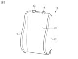
- FIG. 1 is a perspective view of a reinforcing member according to an embodiment
- FIG. Figure 2 is a plan view of the nonwoven prior to being formed into the reinforcement of Figure 1
- FIG. 4 is a cross-sectional view of a foamed molded article manufactured by the method of FIG. 3; It is a flow which shows the manufacturing method of the nonwoven fabric of FIG.
- It is a schematic diagram which shows the lamination process of FIG.
- FIG. 5 is a schematic diagram explaining the needle punch process of FIG. 5, and a heat processing process.
- FIG. 8 is a side view of a needle used in the needle punching process of FIG.
- FIG. 7 is a perspective view of a molding apparatus for molding the stiffener of FIG. 1;
- FIG. FIG. 10 is a perspective view showing how the forming apparatus of FIG. 9 is covered with a nonwoven fabric;
- FIG. 10 is a perspective view showing how a nonwoven fabric is formed using the forming apparatus of FIG. 9;
- FIG. 10 is a perspective view of a first auxiliary cover included in the molding apparatus of FIG. 9;
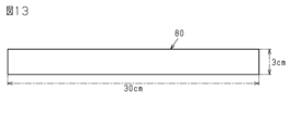
- Fig. 2 is a plan view of a test piece used for measurement of delamination strength;
- FIG. 14 is a schematic diagram showing how the test piece of FIG. 13 is used to measure the delamination strength.
- FIG. 10 is a perspective view showing how the forming apparatus of FIG. 9 is covered with a nonwoven fabric;
- FIG. 10 is a perspective view showing how a nonwoven fabric is formed using the forming apparatus of FIG. 9;
- FIG. 10 is a perspective view of a first auxiliary cover included in the molding apparatus of FIG. 9;
- a nonwoven fabric used as a reinforcing material for a foam molded product that is joined to a foam molded product to reinforce the foam molded product is a single-layer material in which laminated webs are mutually bonded, and has a weight of 7 g/cm 2 . It has a thickness under load of 1 to 8 mm and a delamination strength of 0.05 to 2.45 N/cm, said delamination strength being the amount of tensile force required to separate said bonded webs from each other. value.
- the nonwoven fabric used in the foam reinforcement that is bonded to the foam to reinforce the foam is a single layer material in which laminated webs are bonded together, 7 g/ The thickness at a cm 2 load is 2.5-6 mm and the delamination strength is 0.05-2.45 N/cm, said delamination strength being sufficient to separate said bonded webs from each other. It is the value of the required pulling force.
- the nonwoven fabric When the nonwoven fabric is manufactured by needle punching, for example, the laminated webs are bonded together by entangling the fibers with a plurality of needles having protrusions.
- the higher the delamination strength value the stronger the fibers are bound, and the higher the punch density in the needle punching process, the higher the delamination strength.
- a nonwoven fabric with a high punch density contains many through-holes generated by needle penetration. Therefore, a nonwoven fabric having a high punch density allows the foam material to easily pass through when joined to the foam molding material. Therefore, the foam material is likely to be exposed on the surface of the molded product.
- the nonwoven fabric of the present disclosure has an interlaminar peel strength of 0.05 to 2.45 N/cm by bonding the webs to such an extent that the webs peel from each other when pulled.
- the lower limit of the delamination strength of 0.05 N / cm is the minimum required strength for maintaining the shape of the nonwoven fabric
- the upper limit of the delamination strength of 2.45 N / cm is the shape of the layer. It is the maximum value at which the non-woven fabric can be peeled off.
- the delamination strength is less than the lower limit of 0.05 N/cm, it means that it is difficult to use as a nonwoven fabric, and if the delamination strength is greater than the upper limit of 2.45 N/cm, it means that the webs It means that the layer cannot be peeled off. Therefore, with conventional nonwoven fabrics, even if it is attempted to separate the webs from each other, it is not possible to separate the webs from each other in the thickness direction while maintaining the shape of the layers.
- the nonwoven fabric of the present disclosure may have a thickness of 1-8 mm at 7 g/cm 2 load, or 2.5-6 mm at 7 g/cm 2 load. If the nonwoven fabric is thickened, the passage of the foam material can be suppressed, but the workability during molding deteriorates. More specifically, if the thickness is less than 1 mm, the foam material will easily pass through, and if the thickness exceeds 8 mm, workability will be poor. In this respect, if the thickness of the nonwoven fabric having the above delamination strength is set to 1 to 8 mm under a load of 7 g/cm 2 , it is possible to achieve both suppression of exposure of the foam material and good workability.
- non-woven fabrics which are multi-layered materials, can suppress the passage of foamed materials, but the workability during molding deteriorates. Therefore, if the nonwoven fabric has the above-described delamination strength, even if it is a single-layer material, it is possible to appropriately suppress the passage of the foam material, and since it is a single-layer material, it is excellent in workability. In addition, the single-layer material is generally cheaper than the multi-layer material, so it is economical.
- the web used to manufacture such nonwoven fabrics is not limited to needle punching, but can also be formed using an air laying machine that aligns short fibers with an air flow.
- the nonwoven fabric of the present disclosure can be produced by adjusting at least one of the heating temperature, compression distance, and compression time.
- the web may contain 20-60% by weight of polyethylene terephthalate fibers and 40-80% by weight of polypropylene fibers.
- Polypropylene (PP) has a lower specific gravity than polyethylene terephthalate (PET). Therefore, by including PP, the number of fibers can be increased without increasing the weight. By increasing the number of fibers constituting the nonwoven fabric, it is possible to suppress passage of the foam material.
- the polyethylene terephthalate fiber may have a core-sheath structure, and the core-sheath structure may include a core and a sheath having a lower melting point than the core. According to this configuration, the fibers can be bonded to each other by melting the sheath by heating, while the strength of the fibers can be maintained by the core, which is difficult to melt.
- the nonwoven fabric has a heat-treated first surface, a heat-treated second surface opposite to the first surface, and a heat-treated second surface between the first surface and the second surface. and non-heat-treated inner fibers in.
- the above nonwoven fabric is processed so that the bonding of the web is not strong, so the surface tends to become fuzzy.
- the nonwoven fabric will become stiff and will have poor formability. Since the nonwoven fabric of the present disclosure is heat-treated only on the surface, fuzzing is suppressed. Also, since the internal fibers between the first and second surfaces are not heat treated, good workability can be maintained.
- a reinforcing material for a foam molded article formed from the above nonwoven fabric In particular, a reinforcing material for a foam-molded article obtained by molding the above nonwoven fabric by a molding process accompanied by heating.
- a reinforcing material with high molding accuracy can be obtained.
- the high workability of the nonwoven fabric is useful when the reinforcing material is three-dimensionally formed by a molding process involving heating.
- the method for producing a nonwoven fabric used as a reinforcing material for a foam molded product includes joining laminated webs together by needle punching to form a single-layer material, and heat-treating only the surface of the single-layer material. and adding, the nonwoven fabric has a thickness of 1 to 8 mm at a load of 7 g/cm 2 and a delamination strength of 0.05 to 2.45 N/cm, wherein the delamination strength is is the value of the pulling force required to separate the webs that have been bonded together.
- a method for manufacturing a nonwoven fabric used as a reinforcing material for a foam molded product includes joining laminated webs to each other by needle punching to form a single layer material, and applying only the surface of the single layer material. applying a heat treatment, wherein the nonwoven fabric has a thickness of 2.5 to 6 mm at a load of 7 g/cm 2 and a delamination strength of 0.05 to 2.45 N/cm, and the delamination Strength is the amount of pulling force required to separate the bonded webs from each other.
- a single layer material having a delamination strength of 0.05 to 2.45 N/cm can be formed. Further, by heat-treating only the surface of the single-layer material, the thickness can be adjusted to 1 to 8 mm under a load of 7 g/cm 2 .
- the heat-treated surface suppresses fluffing caused by low punch density.
- the nonwoven fabric is heated to the inside, the internal fibers of the nonwoven fabric are altered by the heat, and the rigidity of the nonwoven fabric increases. Nonwoven fabrics with increased rigidity have poor workability. Therefore, a nonwoven fabric whose surface is heat-treated so as not to heat the internal fibers has excellent moldability.
- a reinforcing material for foam molded product 10 is, for example, a seat pad for reinforcing a cushion material of an automobile seat.
- the cushion material is an example of the foam molded product 19 (see FIG. 4).
- the foam molded product 19 is not limited to a seat pad, and may be, for example, a cushioning material for furniture.
- the reinforcing member 10 has a back portion 12 corresponding to the surface of the backrest, two side portions 13 projecting from the left and right sides of the back portion 12 toward the front of the vehicle, and two through holes 14 corresponding to the mounting locations of the headrest. You may
- the reinforcing material 10 is obtained, for example, by molding or sewing the nonwoven fabric 11 shown in FIG. Molding can be performed by any method such as press molding or vacuum molding.
- the nonwoven fabric 11 is obtained by cutting a nonwoven fabric sheet 33 (see FIG. 7) into a desired shape, for example, the shape of the backrest of an automobile seat.
- the nonwoven fabric 11 may comprise a central wrap 15 and two side wraps 16 .
- the central wrapping portion 15 is a portion that wraps around the back surface of the back portion 12 during molding.
- the side wrapping portion 16 is a portion that wraps around the rear surface of the side portion 13 during molding.
- the nonwoven fabric 11 of the present disclosure is a single layer material manufactured by a needle punching method. More specifically, a plurality of layers of webs formed from short fibers are superimposed and the fibers of those layers are entangled with each other by reciprocating motion of metal needles to form a single layer material.
- the number of web layers to be superimposed is, for example, seven layers, but is not limited to this and can be arbitrarily changed.
- the reinforcing member 10 may be molded using a mold 20.
- the stiffener 10 may be bonded to the foam 18 .
- the mold 20 may include an upper mold 21 , a core mold 22 and a lower mold 23 .
- the reinforcement member 10 is set to cover the core mold 22, for example.
- a foaming material 17 containing a foaming agent, such as urethane is injected into the mold 20 .
- the foam molding material 18 is foam-molded.
- the reinforcing material 10 provides a gap for releasing gas in the mold 20 during foam molding of the foam molding material 18 .
- the foam molded product 19 may include a foam molded material 18 and a reinforcing material 10 joined to the foam molded material 18 .
- the stiffener 10 may be arranged to protect the surface of the foam molding 18 .
- the stiffeners 10 may be placed in those parts of the foam molding 19 that come into contact with metal parts, for example pipe frames or springs. The interposition of the reinforcing material 10 suppresses the abnormal noise caused by the foam molding material 18 rubbing against the metal parts.
- FIG. 5 shows an example of a method for manufacturing the nonwoven fabric 11.
- the web 31 (see FIG. 6) is formed in the web forming process of step S11.
- the web 31 is formed by arranging short fibers, which are at least one of polyethylene terephthalate fibers and polypropylene fibers, by a machine or an air stream.
- the web 31 may comprise 20-60% by weight polyethylene terephthalate (PET) fibers and 40-80% by weight polypropylene (PP) fibers. As an example, it may be 55% by weight of PP fibers and 45% by weight of PET fibers.
- the basis weight of the nonwoven fabric 11 may be, for example, 50-500 g/m 2 , or 80-250 g/m 2 , more specifically, 140 g/m 2 .
- PP fibers may be used by mixing fibers with different thicknesses. If thin fibers are used, the number of fibers can be increased without changing the weight, so the passage of the foam material 17 can be suppressed.
- PET fibers may have a core-sheath structure. This core-sheath structure may include a core and a sheath having a lower melting point than the core. The melting point of the sheath material may be, for example, around 110°C. The melting point of these fibers can vary depending on the processing method, eg molding.
- the web 31 is laminated in a plurality of layers, for example seven layers, to form the laminated material 30.
- the web 31 may be laminated by folding a continuous elongated web 31 .
- the web 31 may be continuously processed by continuously laminating the laminated material 30 while conveying it in the conveying direction.
- the laminated material 30 is repeatedly pierced with a plurality of needles 40 by needle punching.
- the punch density of the needle punch is set low so that the delamination strength is 0.05 to 2.45 N/cm.
- the delamination strength is the value of the tensile force required to separate the bonded webs 31 from each other. A method for measuring the delamination strength will be described later.
- each needle 40 has multiple projections 41 .
- the needle 40 repeatedly reciprocates so as to pass through the laminated material 30 in forward movement and be pulled out of the laminated material 30 in backward movement.
- the plurality of projections 41 hook the fibers, thereby entangling the fibers between the webs 31 and the laminated web 31 becomes the single layer material 32 .
- One or a plurality of support beds 45 and one or a plurality of moving devices 44 arranged to face the support beds 45 may be arranged on the transport path of the laminated material 30 .
- Each moving device 44 may hold multiple needles 40 .
- two moving devices 44 may be arranged on the transport path.
- the needle 40 may pierce only one side of the laminated material 30 conveyed on the support bed 45 .
- a plurality of, for example, two needle groups 42 and 43 may be arranged in the conveying path of the laminated material 30 .
- Needle groups 42 and 43 may be held by respective moving devices 44 .
- the operation of needle groups 42, 43 may differ from each other.
- the depth of penetration of the needles 40 or the number of penetrations may be different from each other.
- the needle density (the number of penetrations) of the first needle group 42 may be 50 needles/cm 2 and the needle density (the number of penetrations) of the second needle group 43 may be 75 needles/cm 2 .
- the needle density of the first needle group 42 may be 50/cm 2 and the needle density of the second needle group 43 may be 75/cm 2 .
- the needle depth of the first needle group 42 may be 9 mm
- the needle depth of the second needle group 43 may be 3 mm.
- Needle depth is the length that the tip of needle 40 passes through support bed 45 .
- a shallow needle depth results in fewer protrusions 41 passing through the web 31 . Therefore, in the second needle group 43 having a shallow needle depth, the effect of entangling the fibers is lower than in the first needle group 42 .
- the needle depth of the second needle group 43 may be shallow to such an extent that the protrusions 41 do not catch the fibers. This reduces the effect of entangling the fibers.
- Calender rolls 46 may include rolls 47 and 48 that sandwich single layer material 32 and one or more heating devices 49 that heat rolls 47 and 48 .
- Two heating devices 49 may be arranged to heat rolls 47 and 48 respectively.
- the surface temperature of the heating rolls 47 and 48 is, for example, 130.degree.
- the distance between the rolls 47 and 48 is set so as not to crush the single layer material 32 .
- the distance between rolls 47, 48 is, for example, 4 mm.
- the transport speed of the single layer material 32 transported between the rolls 47 and 48 is, for example, 5 m/min.
- the single layer material 32 becomes the nonwoven fabric sheet 33 by applying heat treatment.
- the nonwoven fabric sheet 33 has a heat-treated first surface 33a, a second surface 33b on the opposite side of the first surface 33a, and a heat-treated second surface 33b, and the first surface 33a and the second surface 33b. and the non-heat treated internal fibers 33c in between.
- the purpose of heat treatment processing is to remove fluff from the surface of the single layer material 32, not to heat the internal fibers 33c. Therefore, the heating temperature, the distance between the rolls 47 and 48, and the transport speed in the heat treatment process are within the range where the heat treatment does not reach the inside of the single layer material 32, and the thickness at a load of 7 g / cm 2 is 1 to 8 mm. can be changed arbitrarily.
- the nonwoven fabric sheet 33 having a thickness of 1 to 8 mm under a load of 7 g/cm 2 and an interlayer peel strength of 0.05 to 2.45 N/cm is manufactured.
- the nonwoven fabric sheet 33 may be wound into a roll.
- the winding direction at this time is along the conveying direction at the time of manufacture.
- the nonwoven fabric 11 is obtained.
- the nonwoven fabric 11 has properties substantially similar to those of the nonwoven fabric sheet 33 .
- a molding device 50 for the reinforcing material 10 shown in FIG. 9 includes, for example, a molding die 51, legs 53 and 54, a base 60, and an air supply/exhaust unit 61. As shown in FIG. Mold 51 has an internal space and a plurality of vent holes 51a communicating with the internal space. The mold 51 may have two cylindrical portions 52 at positions corresponding to the headrest. The molding die 51 may be supported by the base 60 via the air supply leg portion 53 and the exhaust leg portion 54 .
- the base 60 has an air supply path 60a and an exhaust path 60b inside.
- the air supply path 60a and the exhaust path 60b may communicate with the internal space of the mold 51 through the air supply leg portion 53 and the exhaust leg portion 54, respectively.
- the air supply path 60a and the exhaust path 60b may communicate with the air supply/exhaust unit 61 through an air supply pipe 62 and an exhaust pipe 63, respectively.
- the air supply/exhaust unit 61 may be configured to supply heated steam or heated air through the air supply pipe 62 . Further, the air supply/exhaust unit 61 may be configured to take air through the exhaust pipe 63 .
- the nonwoven fabric 11 to be molded is covered with a molding die 51 .
- the molding device 50 may further include a cover material 64, a first auxiliary cover 70, and two second auxiliary covers 56.
- the first auxiliary cover 70 may be arranged between the air supply leg 53 and the exhaust leg 54 .
- the first auxiliary cover 70 includes two cover bodies 71, four magnets 72, and a connecting bar 73.
- the connecting bar 73 connects the two cover bodies 71 .
- Each cover body 71 has an edge region 71a curved along the bottom edge of the mold 51.
- Two magnets 72 are attached to each cover body 71 so as to face each other.
- a magnet (not shown) may be arranged in the lower end region of the mold 51 .
- the first auxiliary cover 70 may be fixed to the mold 51 by magnets 72 so as to fix the lower end of the nonwoven fabric 11 covering the mold 51 to the mold 51 .
- the two second auxiliary covers 56 are attached to the sides of the mold 51 so as to hold down the side portions 13 of the nonwoven fabric 11 . or fixed with screws. Furthermore, the nonwoven fabric 11 may be fixed to the mold 51 with a plurality of strings 58 .
- the cover material 64 forms the closed space 65 by fixing the edge of the cover material 64 to the base 60 while covering the mold 51 . At this time, the auxiliary covers 56 and 70 are arranged inside the closed space 65 .
- the air supply/exhaust unit 61 supplies heated steam or heating steam or Supply heated air. Thereby, the nonwoven fabric 11 and the mold 51 are heated. At this time, the supplied heating steam inflates the cover material 64 .
- the air supply/exhaust unit 61 exhausts the air from the closed space 65 by sucking through the exhaust pipe 63, the exhaust path 60b, the exhaust leg 54, and the ventilation hole 51a.
- the swollen cover material 64 contracts so as to be attracted to the molding die 51 .
- the nonwoven fabric 11 which has been heated and has increased plasticity, adheres to the molding die 51 and is molded into a shape along the outer shape of the molding die 51 .
- the covered portions of the nonwoven fabric 11 covered with the auxiliary covers 56 and 70 are not only difficult to heat, but also cannot be pressed against the mold 51 by the cover material 64 . Therefore, this covered portion has lower rigidity and is softer than the other portions. That is, the reinforcing member 10 has a first portion having a first rigidity (the portion not covered by the auxiliary covers 56 and 70) and a second portion having a second rigidity lower than the first rigidity (auxiliary covered portion covered with the covers 56 and 70). By arranging the second portion at a portion of the foam molded product 19 where abnormal noise is likely to occur, the generation of abnormal noise can be suppressed.
- the molding device 50 does not have to include at least one of the first auxiliary cover 70 and the second auxiliary cover 56 .
- the molding method of the reinforcing member 10 may not include at least one of the first auxiliary cover fixing step and the second auxiliary cover fixing step.
- test piece 80 A method for measuring the delamination strength will be described below. As shown in FIG. 13, the nonwoven fabric sheet 33 (see FIG. 7) is cut to prepare a test piece 80 having a width of 3 cm and a length of 30 cm. The width and length of the test piece 80 can be changed, but the width is preferably 1 cm or more.
- the longitudinal end regions of the test piece 80 are delaminated by about 50 mm.
- the length of the end region to be peeled off in the preparation step can be arbitrarily changed as long as the peeling length required for the test can be secured.
- “delamination” refers to separating the non-woven fabric webs, which have been made into single-layer materials by needle punching, into the first layer 81 and the second layer 82.
- the first layer 81 includes the first surface 33a and the second layer 82 includes the second surface 33b.
- test strip 80 may be delaminated by 20 cm at a tensile rate of 970 mm/min.
- the pulling speed and peel length can be changed arbitrarily. Any device can be used as the tensile tester as long as the tensile strength can be measured.
- Table 1 shows the test results of delamination strength using Examples 1-4.
- Examples 1 to 4 are test pieces 80 made of nonwoven fabric formed using the same web, and have different punch densities.
- Example 2 has a higher punch density than Example 1
- Example 3 has a higher punch density than Example 2.
- Example 4 has a lower punch density than Example 1.
- the same test was performed 10 times. The results of each ten tests, ie the tensile force, were averaged and divided by 3 in order to convert the average value to strength per unit width (1 cm width). The value thus calculated is the delamination strength.
- the delamination strength of Examples 1 to 4 are all in the range of 0.05 to 2.45 N/cm. In order to calculate a stable value, the delamination strength can be measured multiple times and the average value can be taken, but the number of tests can be changed arbitrarily.
- Comparative examples in Table 1 are conventional nonwoven fabrics. In the comparative example, even if it is subjected to the delamination strength test, it does not separate into two layers, so the value of the delamination strength cannot be calculated.
- Table 1 shows the test results of the degree of exudation using Examples 1 to 4 and Comparative Example. The degree of exudation was determined by creating test pieces of 30 cm x 30 cm each from the nonwoven fabrics of Examples 1 to 4 and Comparative Example, joining each test piece with a foam material in a test mold, and then passing through the test piece. The ratio (%) of the exposed area of the exuded foam material was calculated visually. Visual observation was performed by a plurality of people, and numerical values were determined in increments of 5%.
- the conventional nonwoven fabric has a bleeding degree of 80%
- the bleeding degrees of Examples 1 to 4 are 40%, 60%, 65%, and 30%, respectively. It can be seen that the lower the punch density, the smaller the degree of bleeding.
- the nonwoven fabric 11 may be pinched and delaminated. That is, when the nonwoven fabric 11 is manually pulled in the thickness direction, if the nonwoven fabric 11 can be separated into two layers while maintaining the layered shape without being partially torn, the delamination strength required for the nonwoven fabric 11 can be obtained. You can judge that you are ready. In other words, a nonwoven fabric that does not have delamination strength cannot be separated into two layers, and a nonwoven fabric that cannot be separated into two layers cannot obtain a numerical value for delamination strength itself.
- the nonwoven fabric 11 (or nonwoven fabric sheet 33) of the present disclosure will be described below.
- the nonwoven fabric 11 the webs 31 are bonded together with a punch density so low that delamination is possible.
- the nonwoven fabric 11 has a delamination strength of 0.05 to 2.45 N/cm.
- Such a nonwoven fabric 11 has fewer holes pierced by the needles 40 than conventional nonwoven fabrics in which the webs are bonded together at a punch density high enough to avoid delamination. Therefore, it is difficult for the foam material 17 to pass through the nonwoven fabric 11 (reinforcing material 10) during foam molding. Therefore, exposure or seepage of the foam material 17 to the surface of the foam molded product 19 is suppressed. Therefore, even if the foam molding material 18 rubs against the metal parts via the reinforcing material 10, noise is less likely to occur.
- the nonwoven fabric 11 of the present disclosure the following effects can be obtained.
- the nonwoven fabric 11 having delamination strength makes it difficult for the foam material to pass through.
- the nonwoven fabric 11 is moderately flexible and is a thin single-layer material with a thickness of 1 to 8 mm, it is excellent in moldability. More specifically, since the nonwoven fabric 11 is moderately stretchable, it is easy to set in the mold 20 or the forming mold 51 or to be sewn, and has good conformability to the molds 20 and 51 .
- the web 31 containing PP fibers with a weight ratio of 40 to 80% can increase the number of fibers without increasing the weight as compared with a web consisting only of PET fibers. Since the nonwoven fabric 11 has a larger number of fibers than the conventional one, the passage of the foam material 17 can be suppressed.
- the fibers contained in the nonwoven fabric 11 have a core-sheath structure, the fibers can be bonded to each other by melting the sheath when heated, and the strength of the fibers can be maintained by the hard-to-melt core.
- the surface 33a, 33b of the nonwoven fabric 11 is heat-treated to suppress fluffing.
- the heat treatment does not reach the internal fibers 33c, so the nonwoven fabric 11 is kept flexible. Therefore, the nonwoven fabric 11 is excellent in workability even in shaping processing involving heating, for example. Further, when the reinforcing material 10 is molded by heating, the effect of reducing molding wrinkles by shrinkage can be further exhibited.
- the nonwoven fabric 11 may be formed by sewing.
- a group of needles that pierce the first surface 33a and a group of needles that pierce the second surface 33b may be arranged in the conveying path of the laminated material 30 .
Abstract
発泡成形品を補強するために発泡成形材に接合される発泡成形品用補強材に用いられる不織布は、積層されたウェブが相互に結合された単層材であり、7g/cm2荷重での厚さが1~8mmであり、層間剥離強度が0.05~2.45N/cmである。層間剥離強度は、結合されたウェブ同士を互いに剥離させるのに要する引っ張り力の値である。
Description
本開示は、発泡成形品用補強材に用いられる不織布、発泡成形品用補強材、及び発泡成形品用補強材に用いられる不織布の製造方法に関する。
発泡成形品用補強材の一例として、発泡ウレタン成形品に接合される不織布がある(例えば特許文献1)。こうした発泡成形品の製造時には、例えば、モールド型内に補強材をセットし、型の内部に発泡ウレタン材料を供給した後に、型を閉じる。すると、ウレタン発泡により生じたガスが不織布の繊維の隙間を通過し、発泡ウレタンが補強材と接合される。
補強材の一例として、車両用座席シートに用いられるシートパットがある。シートパットは、金属部品、例えばパイプフレームまたはスプリングと接する位置に配置されることがある。補強材は、金属部品から受ける局所的な力によって発泡材が損傷することを防ぐために用いられるためである。
発泡成形品の製造時に、繊維の隙間に含浸した発泡材が不織布を通過すると、成型品の表面に発泡材が露出する。このように露出した発泡材に金属部材が接触すると、摩擦によって異音が生じる。こうした異音の発生を抑制するために、複数の不織布層が積層された多層材を用いることがある。不織布層の1つとして、例えばスパンボンド法により製造された緻密な不織布を含むことにより、発泡材の通過を抑制することができるためである。しかし、緻密な層を含む多層材は一般に成形性に劣るという課題がある。
本開示の目的は、発泡成形品用補強材に用いられる不織布、発泡成形品用補強材、及び発泡成形品用補強材に用いられる不織布の製造方法を提供することにある。
本開示の一態様に係る、発泡成形品を補強するために発泡成形材に接合される発泡成形品用補強材に用いられる不織布は、積層されたウェブが相互に結合された単層材であり、7g/cm2荷重での厚さが1~8mmであり、層間剥離強度が0.05~2.45N/cmであり、前記層間剥離強度は、結合された前記ウェブ同士を互いに剥離させるのに要する引っ張り力の値である。
[本開示の実施形態の説明]
最初に本開示の実施態様を列記して説明する。
[1]発泡成形品を補強するために発泡成形材に接合される発泡成形品用補強材に用いられる不織布は、積層されたウェブが相互に結合された単層材であり、7g/cm2荷重での厚さが1~8mmであり、層間剥離強度が0.05~2.45N/cmであり、前記層間剥離強度は、結合された前記ウェブ同士を互いに剥離させるのに要する引っ張り力の値である。
最初に本開示の実施態様を列記して説明する。
[1]発泡成形品を補強するために発泡成形材に接合される発泡成形品用補強材に用いられる不織布は、積層されたウェブが相互に結合された単層材であり、7g/cm2荷重での厚さが1~8mmであり、層間剥離強度が0.05~2.45N/cmであり、前記層間剥離強度は、結合された前記ウェブ同士を互いに剥離させるのに要する引っ張り力の値である。
別の例では、発泡成形品を補強するために発泡成形材に接合される発泡成形品用補強材に用いられる不織布は、積層されたウェブが相互に結合された単層材であり、7g/cm2荷重での厚さが2.5~6mmであり、層間剥離強度が0.05~2.45N/cmであり、前記層間剥離強度は、結合された前記ウェブ同士を互いに剥離させるのに要する引っ張り力の値である。
不織布は、例えばニードルパンチにより製造される場合、突起を有する複数のニードルで繊維同士を絡ませることにより、積層されたウェブ同士が結合されている。層間剥離強度は、値が大きいほど強固に繊維が結合されていることを意味し、ニードルパンチ加工におけるパンチ密度が高いほど層間剥離強度は高くなる。パンチ密度が高い不織布は、ニードルの貫通により生じた貫通孔を多く含む。そのため、パンチ密度が高い不織布は、発泡成形材と接合される際に発泡材が通過しやすい。したがって、成形品の表面に発泡材が露出しやすくなる。
本開示の不織布は、引っ張ればウェブ同士が互いに剥離する程度にウェブを結合させることにより、0.05~2.45N/cmの層間剥離強度を有する。ここで、層間剥離強度の下限値0.05N/cmは、不織布としての形状を保つために最低限必要な強度であり、層間剥離強度の上限値2.45N/cmは、層の形状を保ちつつ不織布を剥離させることができる最大の値である。言い換えると、層間剥離強度が下限値0.05N/cm未満ということは、不織布として使用が困難であることを意味し、層間剥離強度が上限値2.45N/cmより大きいということは、ウェブ同士を層状に剥離させることはできないことを意味する。したがって、従来の不織布であれば、ウェブ同士を剥離させようとしても、層の形状を保ちつつ厚さ方向にウェブ同士を剥離させることができない。
また、本開示の不織布は、7g/cm2荷重での厚さが1~8mmであってもよく、または、7g/cm2荷重で2.5~6mmであってもよい。不織布を厚くすると発泡材の通過を抑制できるものの、成形時の加工性が悪化する。より詳細には、厚さが1mm未満になると発泡材が通過しやすくなり、厚さが8mmを超えると加工性が悪くなる。その点、上記層間剥離強度を有する不織布の厚さを7g/cm2荷重において1~8mmとすれば、発泡材の露出抑制と良好な加工性とを両立することができる。
さらに、多層材である不織布は、発泡材の通過を抑制できるものの、成形時の加工性が悪化する。したがって、上記層間剥離強度を有する不織布であれば、単層材であっても適切に発泡材の通過を抑制でき、かつ、単層であるために加工性に優れる。また、単層材は多層材に比べて一般に安価であるため、経済性に優れる。
こうした不織布の製造に用いるウェブは、ニードルパンチ加工に限らず、空気流で短繊維を並べるエアレー式の機械を用いて形成することもできる。エアレー式の機械を用いる場合には、加熱温度、圧縮距離、および圧縮時間のうち少なくとも1つを調整することにより、本開示の不織布を製造することができる。
[2]前記ウェブは、重量比20%~60%のポリエチレンテレフタレート繊維と、重量比40~80%のポリプロピレン繊維とを含んでもよい。
ポリプロピレン(PP)はポリエチレンテレフタレート(PET)よりも比重が小さい。そのためPPを含むことにより、重さを増すことなく繊維本数を増やすことができる。不織布を構成する繊維の本数を増やすことにより、発泡材の通過を抑制することができる。
ポリプロピレン(PP)はポリエチレンテレフタレート(PET)よりも比重が小さい。そのためPPを含むことにより、重さを増すことなく繊維本数を増やすことができる。不織布を構成する繊維の本数を増やすことにより、発泡材の通過を抑制することができる。
[3]前記ポリエチレンテレフタレート繊維は芯鞘構造を有し、前記芯鞘構造は、芯と、前記芯よりも融点が低い鞘とを含んでもよい。
この構成によれば、加熱により鞘が溶融することで繊維同士を結合させつつ、溶融しにくい芯により繊維の強度を維持することができる。
この構成によれば、加熱により鞘が溶融することで繊維同士を結合させつつ、溶融しにくい芯により繊維の強度を維持することができる。
[4]前記不織布は、熱処理された第1面と、前記第1面の反対側の第2面であって、熱処理された第2面と、前記第1面と前記第2面との間にある熱処理されていない内部繊維と、を含んでもよい。
上記不織布は、ウェブの結合が強くならないように加工されているため、表面が毛羽立ちやすい。また、内部繊維が熱処理されていると、不織布が固くなり、成形性が悪くなる。本開示の不織布は表面のみに熱処理が施されているので、毛羽立ちが抑制される。また、第1面と第2面との間にある内部繊維は熱処理されていないので良好な加工性を維持することができる。
[5]上記不織布によって成形された発泡成形品用補強材。特に、上記不織布を加熱を伴う成形加工により成形することにより得られる発泡成形品用補強材。
成形性の高い上記不織布を成形することにより、成形の精度が高い補強材を得ることができる。特に、加熱を伴う成形加工により補強材を立体的に成形する場合には、上記不織布の加工性の高さが有用である。
成形性の高い上記不織布を成形することにより、成形の精度が高い補強材を得ることができる。特に、加熱を伴う成形加工により補強材を立体的に成形する場合には、上記不織布の加工性の高さが有用である。
[6]発泡成形品用補強材に用いられる不織布の製造方法は、積層されたウェブをニードルパンチにより相互に結合させて単層材に加工することと、前記単層材の表面のみに熱処理を加えることと、を含み、前記不織布は、7g/cm2荷重での厚さが1~8mmであり、層間剥離強度が0.05~2.45N/cmであり、前記層間剥離強度は、結合された前記ウェブ同士を互いに剥離させるのに要する引っ張り力の値である。
別の例では、発泡成形品用補強材に用いられる不織布の製造方法は、積層されたウェブをニードルパンチにより相互に結合させて単層材に加工することと、前記単層材の表面のみに熱処理を加えることと、を含み、前記不織布は、7g/cm2荷重での厚さが2.5~6mmであり、層間剥離強度が0.05~2.45N/cmであり、前記層間剥離強度は、結合された前記ウェブ同士を互いに剥離させるのに要する引っ張り力の値である。
積層されたウェブを相互にニードルパンチにより結合させる際にパンチ密度を調整することにより、層間剥離強度が0.05~2.45N/cmの単層材を形成することができる。また、単層材の表面のみに熱処理を加えることにより、7g/cm2荷重での厚さが1~8mmとなるように調整することができる。熱処理が加えられた表面は、パンチ密度が低いことに起因して生じる毛羽立ちが抑制される。このとき、不織布を内部まで加熱すると、不織布の内部繊維が熱により変質して、不織布の剛性が増す。剛性の増した不織布は加工性が悪くなる。そのため、内部繊維を加熱しないように表面のみを加熱処理した不織布は、成形性に優れる。
[本開示の実施形態の詳細]
図1に示すように、本開示の一態様に係る発泡成形品用補強材10は、例えば、自動車用シートのクッション材を補強するためのシートパットである。クッション材は、発泡成形品19(図4参照)の一例である。発泡成形品19はシートパットに限らず、例えば、家具のクッション材であってもよい。
図1に示すように、本開示の一態様に係る発泡成形品用補強材10は、例えば、自動車用シートのクッション材を補強するためのシートパットである。クッション材は、発泡成形品19(図4参照)の一例である。発泡成形品19はシートパットに限らず、例えば、家具のクッション材であってもよい。
補強材10は、背もたれの表面に対応する背部12と、背部12の左右から車両の前方に向かって張り出す2つの側部13と、ヘッドレストの取り付け箇所に対応する2つの貫通孔14とを有してもよい。補強材10は、例えば、図2に示す不織布11を成形または縫製することによって得られる。成形は、プレス成形または真空成形など、任意の手法で行うことができる。
図2に示すように、不織布11は、不織布シート33(図7参照)を目的の形状、例えば自動車用シートの背もたれの形状に裁断することによって得られる。不織布11は、中央回り込み部15と2つの側方回り込み部16とを備えてもよい。中央回り込み部15は、成形時に背部12の背面に回り込む部分である。側方回り込み部16は、成形時に側部13の背面に回り込む部分である。
本開示の不織布11は、ニードルパンチ法により製造される単層材である。より詳細には、短繊維から形成されたウェブを複数層重ね合わせ、それら層の繊維を金属製ニードルの往復運動により互いに交絡させて一枚の単層材を形成する。重ね合わせるウェブの層数は、例えば7層であるが、これに限定されず、任意に変更することができる。
図3に示すように、補強材10はモールド型20を用いて成形されてもよい。このモールド型20の中で、補強材10は発泡成形材18に接合されてもよい。モールド型20は、上型21、中子型22、及び下型23を含んでもよい。補強材10は、例えば中子型22を覆うようにセットされる。その後、発泡剤を含む発泡材17、例えばウレタンをモールド型20内に注入する。これにより、発泡成形材18が発泡成形される。補強材10は、発泡成形材18の発泡成形時に、モールド型20内のガスを抜くための隙間を提供する。
図4に示すように、発泡成形品19は、発泡成形材18と、発泡成形材18に接合された補強材10とを含んでもよい。補強材10は、発泡成形材18の表面を保護するように配置されてもよい。補強材10は、発泡成形品19のうち、金属部品、例えばパイプフレームまたはスプリングに触れる部分に配置されてもよい。補強材10に介在により、発泡成形材18が金属部品とこすれて生じる異音が抑制される。
[不織布の製造方法]
図5に、不織布11の製造方法の一例を示す。
まず、ステップS11のウェブ形成工程においてウェブ31(図6参照)を形成する。ウェブ31は、ポリエチレンテレフタレート繊維及びポリプロピレン繊維のうち少なくとも一方である短繊維を機械または空気流によって並べることにより、形成される。
図5に、不織布11の製造方法の一例を示す。
まず、ステップS11のウェブ形成工程においてウェブ31(図6参照)を形成する。ウェブ31は、ポリエチレンテレフタレート繊維及びポリプロピレン繊維のうち少なくとも一方である短繊維を機械または空気流によって並べることにより、形成される。
ウェブ31は、重量比20%~60%のポリエチレンテレフタレート(PET)繊維と、重量比40~80%のポリプロピレン(PP)繊維とを含んでもよい。一例として、PP繊維が55重量%、PET繊維が45重量%であってもよい。不織布11の目付は、例えば50~500g/m2であってもよく、あるいは80~250g/m2であってもよく、より詳細には、140g/m2であってもよい。
PP繊維は、太さが異なる繊維を混合して用いてもよい。細い繊維を用いれば、重量を変えずに繊維本数を増すことができるので、発泡材17の通過を抑制することができる。PET繊維は芯鞘構造を有してもよい。この芯鞘構造は、芯と、芯よりも融点が低い鞘とを含んでもよい。鞘材料の融点は例えば110℃程度であってもよい。これら繊維の融点は、例えば成形等の加工方法に応じて変更することができる。
図6に示すように、ステップS12の積層工程において、ウェブ31を複数層、例えば7層に積層して積層材30を形成する。ウェブ31は、連続的に延びる長尺状のウェブ31折り重ねていくことで積層してもよい。ウェブ31は、積層材30を搬送方向に搬送しながら連続的に積層していくことで、連続的に加工に供するようにしてもよい。
図7に示すように、ステップS13のニードルパンチ工程において、積層材30に複数のニードル40により繰り返し突き刺す、ニードルパンチ加工を施す。ニードルパンチ工程では、層間剥離強度が0.05~2.45N/cmになるように、ニードルパンチのパンチ密度を低く設定する。層間剥離強度は、結合されたウェブ31同士を互いに剥離させるのに要する引っ張り力の値である。層間剥離強度の測定方法は後述する。
図8に示すように、各ニードル40は複数の突起41を有する。
図7に示すように、ニードル40は、往動で積層材30を貫通し、復動で積層材30から引き抜かれるように、繰り返し往復移動する。この往復移動に伴って複数の突起41(図8参照)が繊維を引っかけることにより、ウェブ31間で繊維が互いに絡みあい、積層されたウェブ31が単層材32となる。
図7に示すように、ニードル40は、往動で積層材30を貫通し、復動で積層材30から引き抜かれるように、繰り返し往復移動する。この往復移動に伴って複数の突起41(図8参照)が繊維を引っかけることにより、ウェブ31間で繊維が互いに絡みあい、積層されたウェブ31が単層材32となる。
積層材30の搬送経路には、1または複数の支持ベッド45と、支持ベッド45と対抗するように配置される1または複数の移動装置44を配置してもよい。各移動装置44は、複数のニードル40を保持してもよい。例えば、搬送経路には、2つの移動装置44を配置してもよい。
ニードル40は、支持ベッド45上を搬送される積層材30の片面のみから刺すようにしてもよい。また、積層材30の搬送経路には複数、例えば2つのニードル群42,43を配置してもよい。ニードル群42,43は、それぞれ対応する移動装置44に保持されてもよい。ニードル群42,43の動作は互いに異なっていてもよい。例えばニードル群42,43において、ニードル40を突き刺す深さ、またはペネ数を互いに異ならせてもよい。
例えば、第1ニードル群42の針密度(ペネ数)を50本/cm2とし、第2ニードル群43の針密度(ペネ数)を75本/cm2にしてもよい。あるいは、第1ニードル群42の針密度を50本/cm2とし、第2ニードル群43の針密度を75本/cm2にしてもよい。
例えば、第1ニードル群42の針深度を9mmにして、第2ニードル群43の針深度を3mmにしてもよい。針深度は、ニードル40の先端が支持ベッド45を通過する長さである。針深度が浅いと、ウェブ31を通過する突起41の数が少なくなる。そのため、針深度が浅い第2ニードル群43では、繊維同士を絡ませる効果が第1ニードル群42よりも低い。第2ニードル群43は、突起41が繊維を引っかけない程度に針深度を浅くしてもよい。これにより、繊維を絡ませる効果が低くなる。
ステップS14に示す熱処理工程において、カレンダーロール46により、7g/cm2荷重での厚さが1~8mmとなるように、単層材32の表面にのみ熱処理加工を施す。カレンダーロール46は、単層材32を挟むロール47,48と、ロール47,48を加熱する1または複数の加熱装置49とを備えてもよい。2つの加熱装置49は、それぞれロール47,48を加熱するように配置してもよい。加熱ロール47,48の表面温度は例えば130℃である。ロール47,48間の距離は、単層材32を押しつぶさない距離に設定される。ロール47,48間の距離は、例えば4mmである。ロール47,48間を搬送される単層材32の搬送速度は、例えば5m/分である。
熱処理加工を施すことにより、単層材32は不織布シート33となる。不織布シート33は、熱処理された第1面33aと、第1面33aの反対側の第2面33bであって、熱処理された第2面33bと、第1面33aと第2面33bとの間にある熱処理されていない内部繊維33cとを含む。
熱処理加工の目的は、単層材32の表面の毛羽をとることであって、その内部繊維33cを加熱することではない。よって、熱処理工程における加熱温度、ロール47,48間距離、及び搬送速度は、単層材32の内部にまで熱処理が及ばない範囲で、7g/cm2荷重での厚さが1~8mmとなるように、任意に変更することができる。
上記ステップS11~S14により、7g/cm2荷重での厚さが1~8mmであり、層間剥離強度が0.05~2.45N/cmである、不織布シート33が製造される。不織布シート33はロール状に巻かれてもよい。このときの巻き方向は製造時の搬送方向に沿う。不織布シート33を目的の形状に裁断すると、不織布11(図2参照)になる。不織布11は不織布シート33と実質的に同様の性質を有する。
[補強材の成形方法]
以下に、補強材10の製造方法、特にその成形方法の一例を説明する。
図9に示す補強材10の成形装置50は、例えば、成形型51と、脚部53,54と、基台60と、給排気ユニット61と、を備える。成形型51は、内部空間と、内部空間に連通する複数の通気孔51aとを有する。成形型51は、ヘッドレストと対応する位置に2つの筒部52を有してもよい。成形型51は、給気脚部53及び排気脚部54を介して基台60に支持されていてもよい。
以下に、補強材10の製造方法、特にその成形方法の一例を説明する。
図9に示す補強材10の成形装置50は、例えば、成形型51と、脚部53,54と、基台60と、給排気ユニット61と、を備える。成形型51は、内部空間と、内部空間に連通する複数の通気孔51aとを有する。成形型51は、ヘッドレストと対応する位置に2つの筒部52を有してもよい。成形型51は、給気脚部53及び排気脚部54を介して基台60に支持されていてもよい。
基台60は内部に給気路60a及び排気路60bを有している。給気路60a及び排気路60bはそれぞれ給気脚部53及び排気脚部54を通じて成形型51の内部空間と連通していてもよい。給気路60a及び排気路60bは、それぞれ給気管62及び排気管63を通じて給排気ユニット61と連通していてもよい。給排気ユニット61は、給気管62を通じて加熱蒸気または加熱空気を供給するように構成されてもよい。また、給排気ユニット61は、排気管63を通じて吸気するように構成されてもよい。
図10に示す被覆工程において、成形に供される不織布11は、成形型51に被せられる。
図11に示すように、成形装置50は、さらに、カバー材64と、第1補助カバー70と、2つの第2補助カバー56とを備えてもよい。第1補助カバー70は、給気脚部53と排気脚部54との間に配置されてもよい。
図11に示すように、成形装置50は、さらに、カバー材64と、第1補助カバー70と、2つの第2補助カバー56とを備えてもよい。第1補助カバー70は、給気脚部53と排気脚部54との間に配置されてもよい。
図12に示すように、第1補助カバー70は、2つのカバー本体71と、4つの磁石72と、連結バー73とを備える。連結バー73は、2つのカバー本体71を連結する。各カバー本体71は成形型51の下端に沿うように湾曲した縁領域71aを有する。各カバー本体71には、互いに対向するように2つの磁石72が取り付けられている。成形型51の下端領域には、図示しない磁石を配置してもよい。第1補助カバー70は、第1補助カバー固定工程において、成形型51を覆う不織布11の下端を成形型51に対して固定するように磁石72により成形型51に対して固定されてもよい。
図11に示すように、第2補助カバー固定工程において、2つの第2補助カバー56は、不織布11の側部13を押さえるように、それぞれ成形型51の側方に図示しない固定具、例えば磁石またはねじにより固定される。さらに、複数の紐58により不織布11を成形型51に固定してもよい。カバー材64は、空間形成工程において、成形型51を覆った状態で、その端縁が基台60に固定されることで閉塞空間65を形成する。このとき、補助カバー56,70は閉塞空間65内に配置される。
空間形成工程の後、給気工程または加熱工程において、給排気ユニット61が、給気管62、給気路60a、給気脚部53、及び通気孔51aを通じて、成形型51の内部に加熱蒸気または加熱空気を供給する。これにより、不織布11及び成形型51が加熱される。このとき、供給された加熱蒸気によりカバー材64が膨らむ。
その後、排気工程において、給排気ユニット61が、排気管63、排気路60b、排気脚部54、及び通気孔51aを通じて吸引することにより、閉塞空間65から空気を排気する。これにより、膨らんでいたカバー材64は成形型51に吸い寄せられるように収縮する。その結果、加熱されて可塑性が高くなっている不織布11は成形型51に密着し、成形型51の外形に沿った形状に成形される。このような、被覆工程、第1補助カバー固定工程、第2補助カバー固定工程、空間形成工程、給気工程(加熱工程)、及び排気工程を含む成形方法により、図1に示す補強材10が成形される。
不織布11のうち補助カバー56,70で覆われた被覆部分は、加熱されにくいだけでなく、カバー材64によって成形型51に押し付けられない。したがって、この被覆部分は、それ以外の部分よりも剛性が低く、柔らかい。すなわち、補強材10は、第1の剛性を有する第1部分(補助カバー56,70で覆われていなかった部分)と、第1の剛性よりも低い第2の剛性を有する第2部分(補助カバー56,70で覆われていた被覆部分)とを有する。第2部分を、発泡成形品19の異音が発生しやすい箇所に配置することにより、異音の発生を抑えることができる。
成形装置50は、第1補助カバー70及び第2補助カバー56のうち少なくとも一方を備えなくてもよい。言い換えると、補強材10の成形方法は、第1補助カバー固定工程及び第2補助カバー固定工程のうち少なくとも一方を含まなくてもよい。
[層間剥離強度の測定方法]
以下に、層間剥離強度の測定方法を説明する。
図13に示すように、不織布シート33(図7参照)を切断して、幅3cm、長さ30cmの試験片80を作成する。試験片80の幅及び長さは変更可能であるが、幅は1cm以上であることが好ましい。
以下に、層間剥離強度の測定方法を説明する。
図13に示すように、不織布シート33(図7参照)を切断して、幅3cm、長さ30cmの試験片80を作成する。試験片80の幅及び長さは変更可能であるが、幅は1cm以上であることが好ましい。
次に、準備工程として、試験片80の長手方向の端部領域を50mmほど層間剥離させる。準備工程で剥離させる端部領域の長さは、試験に必要な剥離長さが確保できる範囲で、任意に変更できる。
図14に示すように、「層間剥離」とは、ニードルパンチ加工により単層材となった不織布のウェブ同士を剥離させて、第1層81と第2層82とに分離させることをいう。第1層81は第1面33aを含み、第2層82は第2面33bを含む。
続いて、剥離工程において、剥離した第1層81と第2層82とを図示しない引張試験器にて別々に保持し、層間剥離させる。この層間剥離に要する力の最大値が層間剥離強度である。一例として、試験片80を引張速度970mm/分で20cm程層間剥離させてもよい。引張速度および剥離長さは、任意に変更することができる。引張試験器は、引張強度が測定可能であれば、任意の装置を用いることができる。
表1に、実施例1~4を用いた層間剥離強度の試験結果を示す。実施例1~4は、同じウェブを用いて形成された不織布からなる試験片80であって、互いにパンチ密度が異なる。実施例2は実施例1よりもパンチ密度が高く、実施例3は実施例2よりもさらにパンチ密度が高い。実施例4は実施例1よりもパンチ密度が低い。各実施例においては、同様の試験を10回ずつ行った。各10回の試験結果、すなわち引っ張り力を平均し、その平均値を単位幅(1cm幅)での強度に換算するため、3で除算した。このようにして算出された値が層間剥離強度である。

実施例1~4の層間剥離強度から明らかなように、パンチ密度が高ければウェブ間(層間)の結合が強固になるので、層間剥離に要する引っ張り力が大きくなる。すなわち、層間剥離強度が高くなる。実施例1~4の層間剥離強度は、いずれも0.05~2.45N/cmの範囲にある。層間剥離強度の測定は、安定した値を算出するために複数回試験を行って平均値をとることができるが、試験回数は任意に変更できる。
表1の比較例は、従来の不織布である。比較例では、層間剥離強度の試験に供しても2層に剥離しないため、層間剥離強度の数値は算出できない。
実施例1~4及び比較例を用いた染出し度の試験結果を表1に示す。染み出し度は、実施例1~4及び比較例の不織布でそれぞれ30cm×30cmの試験片を作成し、試験用金型内で各試験片を発泡材と接合した後、試験片を通過して染み出した発泡材が露出している面積の割合(%)を目視にて算出した。目視は複数人で行い、5%刻みで数値を決定した。
実施例1~4及び比較例を用いた染出し度の試験結果を表1に示す。染み出し度は、実施例1~4及び比較例の不織布でそれぞれ30cm×30cmの試験片を作成し、試験用金型内で各試験片を発泡材と接合した後、試験片を通過して染み出した発泡材が露出している面積の割合(%)を目視にて算出した。目視は複数人で行い、5%刻みで数値を決定した。
従来の不織布では染み出し度が80%であるのに対して、実施例1~4の染み出し度はそれぞれ40%,60%,65%,30%であり、層間剥離強度が低いほど、すなわちパンチ密度が低いほど、染み出し度が小さいことがわかる。
層間剥離強度の簡易的な判断方法として、不織布11を手でつまんで層間剥離させてもよい。すなわち、手動で不織布11を厚さ方向に引っ張った場合に、部分的にちぎれたりすることなく、層状の形状を保ったままで2層に剥離させることができれば、不織布11に必要な層間剥離強度を備えると判断することができる。つまり、層間剥離強度を有さない不織布は2層に剥離させることができないし、2層に剥離できない不織布は層間剥離強度の数値を得ること自体ができない。
以下、本開示の不織布11(または不織布シート33)の作用を説明する。
不織布11は、層間剥離が可能な程に、低いパンチ密度でウェブ31同士が結合されている。言い換えると、不織布11は、0.05~2.45N/cmの層間剥離強度を有する。こうした不織布11は、層間剥離しない程度に高いパンチ密度でウェブ同士が結合された従来の不織布よりも、ニードル40が貫通した孔が少ない。そのため、発泡成形時に発泡材17が不織布11(補強材10)を通過しにくい。したがって、発泡成形品19の表面への発泡材17の露出あるいは染み出しが抑制される。そのため、発泡成形材18が補強材10を介して金属部品とこすれても、異音が発生しにくい。
不織布11は、層間剥離が可能な程に、低いパンチ密度でウェブ31同士が結合されている。言い換えると、不織布11は、0.05~2.45N/cmの層間剥離強度を有する。こうした不織布11は、層間剥離しない程度に高いパンチ密度でウェブ同士が結合された従来の不織布よりも、ニードル40が貫通した孔が少ない。そのため、発泡成形時に発泡材17が不織布11(補強材10)を通過しにくい。したがって、発泡成形品19の表面への発泡材17の露出あるいは染み出しが抑制される。そのため、発泡成形材18が補強材10を介して金属部品とこすれても、異音が発生しにくい。
本開示の不織布11によれば、以下の効果を奏することができる。
(1)層間剥離強度を有する不織布11は発泡材を通過させにくい。また、こうした不織布11は適度な柔軟性を備える上、単層材であって厚さが1~8mmと薄いので、成形性に優れる。より詳細には、不織布11は、適度に伸びるため、モールド型20または成形型51にセットするとき、あるいは縫製するときに作業がしやすく、また、型20,51への追従性がよい。
(1)層間剥離強度を有する不織布11は発泡材を通過させにくい。また、こうした不織布11は適度な柔軟性を備える上、単層材であって厚さが1~8mmと薄いので、成形性に優れる。より詳細には、不織布11は、適度に伸びるため、モールド型20または成形型51にセットするとき、あるいは縫製するときに作業がしやすく、また、型20,51への追従性がよい。
(2)重量比40~80%のPP繊維を含むウェブ31は、PET繊維のみからなるウェブよりも、重さを増すことなく繊維本数を増やすことができる。不織布11は従来よりも繊維の本数が多いので、発泡材17の通過を抑制することができる。
(3)不織布11に含まれるPET繊維が芯鞘構造を有するので、加熱により鞘が溶融することで繊維同士を結合させつつ、溶融しにくい芯により繊維の強度を維持することができる。
(4)不織布11は、表面33a,33bを熱処理することにより、毛羽立ちが抑制されている。熱処理を表面33a,33bのみに施すことにより、内部繊維33cには加熱処理が及ばないので、不織布11は柔軟性が保たれている。そのため、不織布11は、例えば加熱を伴う整形加工においても、加工性に優れる。また、補強材10を加熱により成形する場合には、収縮によって成形シワを軽減させる効果をより発揮できる。
(5)補強材10は、加工性に優れる不織布11を成形して製造されるので、成形の精度が高い。
[本開示の変更例]
本実施形態は、以下のように変更して実施することができる。本実施形態及び以下の変更例は、技術的に矛盾しない範囲で互いに組み合わせて実施することができる。
[本開示の変更例]
本実施形態は、以下のように変更して実施することができる。本実施形態及び以下の変更例は、技術的に矛盾しない範囲で互いに組み合わせて実施することができる。
・不織布11は、縫製により成形されてもよい。
・積層材30の搬送経路には、第1面33aを刺すニードル群と、第2面33bを刺すニードル群とを配置してもよい。
・積層材30の搬送経路には、第1面33aを刺すニードル群と、第2面33bを刺すニードル群とを配置してもよい。
10…補強材、11…不織布、12…背部、13…側部、14…貫通孔、15…中央回り込み部、16…側方回り込み部込み部、17…発泡材、18…発泡成形材、19…発泡成形品、20…モールド型、21…上型、22…中子型、23…下型、30…積層材、31…ウェブ、32…単層材、33…不織布シート、33a…第1面、33b…第2面、33c…内部繊維、40…ニードル、41…突起、42…第1ニードル群、43…第2ニードル群、44…移動装置、45…支持ベッド、46…カレンダーロール、47…加熱ロール、48…ロール、49…加熱装置、50…成形装置、51…成形型、51a…通気孔、52…筒部、53…給気脚部、54…排気脚部、56…第2補助カバー、58…紐、60…基台、60a…給気路、60b…排気路、61…給排気ユニット、62…給気管、63…排気管、64…カバー材、65…閉塞空間、70…第1補助カバー、71…カバー本体、71a…縁領域、72…磁石、73…連結バー、80…試験片、81…第1層、82…第2層。
Claims (6)
- 発泡成形品を補強するために発泡成形材に接合される発泡成形品用補強材に用いられる不織布であって、前記不織布は、
積層されたウェブが相互に結合された単層材であり、
7g/cm2荷重での厚さが1~8mmであり、
層間剥離強度が0.05~2.45N/cmであり、前記層間剥離強度は、結合された前記ウェブ同士を互いに剥離させるのに要する引っ張り力の値である、
発泡成形品用補強材に用いられる不織布。 - 前記ウェブは、重量比20%~60%のポリエチレンテレフタレート繊維と、重量比40~80%のポリプロピレン繊維とを含む、
請求項1に記載の発泡成形品用補強材に用いられる不織布。 - 前記ポリエチレンテレフタレート繊維は芯鞘構造を有し、
前記芯鞘構造は、芯と、前記芯よりも融点が低い鞘とを含む、
請求項2に記載の発泡成形品用補強材に用いられる不織布。 - 熱処理された第1面と、
前記第1面の反対側の第2面であって、熱処理された第2面と、
前記第1面と前記第2面との間にある熱処理されていない内部繊維と、
を含む、
請求項1または2に記載の発泡成形品用補強材に用いられる不織布。 - 請求項1~3のうち何れか一項に記載の不織布によって成形された、
発泡成形品用補強材。 - 発泡成形品用補強材に用いられる不織布の製造方法であって、
積層されたウェブをニードルパンチにより相互に結合させて単層材に加工することと、
前記単層材の表面のみに熱処理を加えることと、を含み、
前記不織布は、
7g/cm2荷重での厚さが1~8mmであり、
層間剥離強度が0.05~2.45N/cmであり、前記層間剥離強度は、結合された前記ウェブ同士を互いに剥離させるのに要する引っ張り力の値である、
発泡成形品用補強材に用いられる不織布の製造方法。
Applications Claiming Priority (2)
| Application Number | Priority Date | Filing Date | Title |
|---|---|---|---|
| JP2021168789A JP7444408B2 (ja) | 2021-10-14 | 2021-10-14 | 発泡成形品用補強材に用いられる不織布、発泡成形品用補強材、及び発泡成形品用補強材に用いられる不織布の製造方法 |
| JP2021-168789 | 2021-10-14 |
Publications (1)
| Publication Number | Publication Date |
|---|---|
| WO2023063257A1 true WO2023063257A1 (ja) | 2023-04-20 |
Family
ID=85987740
Family Applications (1)
| Application Number | Title | Priority Date | Filing Date |
|---|---|---|---|
| PCT/JP2022/037640 WO2023063257A1 (ja) | 2021-10-14 | 2022-10-07 | 発泡成形品用補強材に用いられる不織布、発泡成形品用補強材、及び発泡成形品用補強材に用いられる不織布の製造方法 |
Country Status (2)
| Country | Link |
|---|---|
| JP (1) | JP7444408B2 (ja) |
| WO (1) | WO2023063257A1 (ja) |
Citations (5)
| Publication number | Priority date | Publication date | Assignee | Title |
|---|---|---|---|---|
| WO2007049627A1 (ja) * | 2005-10-27 | 2007-05-03 | Toyo Boseki Kabushiki Kaisha | 不織布及びその製造方法 |
| JP2012007260A (ja) * | 2010-06-24 | 2012-01-12 | Toyobo Co Ltd | 発泡成形品補強材用不織布及び発泡成形品 |
| JP2013076179A (ja) * | 2011-09-30 | 2013-04-25 | Toyobo Co Ltd | 発泡成形品補強用不織布 |
| JP2013129950A (ja) * | 2011-12-20 | 2013-07-04 | Kurashiki Seni Kako Kk | モールドパッド用不織布及びその製造方法 |
| JP2017226936A (ja) * | 2016-06-24 | 2017-12-28 | 豊田通商株式会社 | ウレタン発泡成形用補強布およびその製造方法 |
-
2021
- 2021-10-14 JP JP2021168789A patent/JP7444408B2/ja active Active
-
2022
- 2022-10-07 WO PCT/JP2022/037640 patent/WO2023063257A1/ja unknown
Patent Citations (5)
| Publication number | Priority date | Publication date | Assignee | Title |
|---|---|---|---|---|
| WO2007049627A1 (ja) * | 2005-10-27 | 2007-05-03 | Toyo Boseki Kabushiki Kaisha | 不織布及びその製造方法 |
| JP2012007260A (ja) * | 2010-06-24 | 2012-01-12 | Toyobo Co Ltd | 発泡成形品補強材用不織布及び発泡成形品 |
| JP2013076179A (ja) * | 2011-09-30 | 2013-04-25 | Toyobo Co Ltd | 発泡成形品補強用不織布 |
| JP2013129950A (ja) * | 2011-12-20 | 2013-07-04 | Kurashiki Seni Kako Kk | モールドパッド用不織布及びその製造方法 |
| JP2017226936A (ja) * | 2016-06-24 | 2017-12-28 | 豊田通商株式会社 | ウレタン発泡成形用補強布およびその製造方法 |
Also Published As
| Publication number | Publication date |
|---|---|
| JP7444408B2 (ja) | 2024-03-06 |
| JP2023058955A (ja) | 2023-04-26 |
Similar Documents
| Publication | Publication Date | Title |
|---|---|---|
| JP5619407B2 (ja) | 成形体、衣料品及び成形体の製造方法 | |
| JP6040166B2 (ja) | 曲げ剛性を備えた積層板、同積層板からの成形品、及びその製造方法 | |
| JP4955530B2 (ja) | 表皮一体発泡成形用の表皮材 | |
| US8727417B2 (en) | Molded laying interior material for vehicle | |
| JP3883008B2 (ja) | 発泡成形体補強材及び車両用座席 | |
| US20220363018A1 (en) | Self-rising board molding | |
| JP2007182661A (ja) | 多軸成形材料、プリフォーム、frpおよびそれらの製造方法 | |
| JP5003028B2 (ja) | 発泡ウレタン補強材 | |
| WO2023063257A1 (ja) | 発泡成形品用補強材に用いられる不織布、発泡成形品用補強材、及び発泡成形品用補強材に用いられる不織布の製造方法 | |
| TW201522737A (zh) | 不織布及強化積層體 | |
| US7407558B2 (en) | Fiber batt having a separator layer | |
| KR20190037024A (ko) | 타공필름과 합성수지 파우더를 갖는 다층구조의 차량용 내장재 및 그 제조방법 | |
| CN118043510A (en) | Nonwoven fabric for use in reinforcing material for foam molded article, and method for producing nonwoven fabric for use in reinforcing material for foam molded article | |
| JP5762766B2 (ja) | 車両シート用内装材とその製造方法 | |
| WO2007049627A1 (ja) | 不織布及びその製造方法 | |
| JPH06136651A (ja) | 発泡成形用被覆材 | |
| JP7219624B2 (ja) | プレス成形体、車両用シートバックボード、およびプレス成形体製造方法 | |
| JPH1112912A (ja) | 2層フェルトの製造方法 | |
| JP6601165B2 (ja) | 発泡成形品及び車両用シート | |
| JP3479701B2 (ja) | 異硬度化繊維質クッション体およびその製造方法 | |
| JP7340950B2 (ja) | 積層体およびその製造方法 | |
| JP5624870B2 (ja) | 発泡成形体および発泡成形体の製造方法 | |
| JP2005177198A (ja) | シート用パッド | |
| JP3543361B2 (ja) | 表皮材およびその製造方法 | |
| JP2004322472A (ja) | 成形内装材 |
Legal Events
| Date | Code | Title | Description |
|---|---|---|---|
| 121 | Ep: the epo has been informed by wipo that ep was designated in this application |
Ref document number: 22880952 Country of ref document: EP Kind code of ref document: A1 |