WO2023063178A1 - リアクトル、コンバータ、及び電力変換装置 - Google Patents
リアクトル、コンバータ、及び電力変換装置 Download PDFInfo
- Publication number
- WO2023063178A1 WO2023063178A1 PCT/JP2022/037180 JP2022037180W WO2023063178A1 WO 2023063178 A1 WO2023063178 A1 WO 2023063178A1 JP 2022037180 W JP2022037180 W JP 2022037180W WO 2023063178 A1 WO2023063178 A1 WO 2023063178A1
- Authority
- WO
- WIPO (PCT)
- Prior art keywords
- core
- middle core
- core portion
- modulus
- young
- Prior art date
- Legal status (The legal status is an assumption and is not a legal conclusion. Google has not performed a legal analysis and makes no representation as to the accuracy of the status listed.)
- Ceased
Links
Images




Classifications
-
- H—ELECTRICITY
- H01—ELECTRIC ELEMENTS
- H01F—MAGNETS; INDUCTANCES; TRANSFORMERS; SELECTION OF MATERIALS FOR THEIR MAGNETIC PROPERTIES
- H01F37/00—Fixed inductances not covered by group H01F17/00
-
- H—ELECTRICITY
- H01—ELECTRIC ELEMENTS
- H01F—MAGNETS; INDUCTANCES; TRANSFORMERS; SELECTION OF MATERIALS FOR THEIR MAGNETIC PROPERTIES
- H01F27/00—Details of transformers or inductances, in general
- H01F27/24—Magnetic cores
-
- H—ELECTRICITY
- H01—ELECTRIC ELEMENTS
- H01F—MAGNETS; INDUCTANCES; TRANSFORMERS; SELECTION OF MATERIALS FOR THEIR MAGNETIC PROPERTIES
- H01F27/00—Details of transformers or inductances, in general
- H01F27/24—Magnetic cores
- H01F27/255—Magnetic cores made from particles
-
- H—ELECTRICITY
- H01—ELECTRIC ELEMENTS
- H01F—MAGNETS; INDUCTANCES; TRANSFORMERS; SELECTION OF MATERIALS FOR THEIR MAGNETIC PROPERTIES
- H01F27/00—Details of transformers or inductances, in general
- H01F27/24—Magnetic cores
- H01F27/26—Fastening parts of the core together; Fastening or mounting the core on casing or support
- H01F27/263—Fastening parts of the core together
-
- H—ELECTRICITY
- H01—ELECTRIC ELEMENTS
- H01F—MAGNETS; INDUCTANCES; TRANSFORMERS; SELECTION OF MATERIALS FOR THEIR MAGNETIC PROPERTIES
- H01F3/00—Cores, Yokes, or armatures
- H01F3/10—Composite arrangements of magnetic circuits
- H01F3/14—Constrictions; Gaps, e.g. air-gaps
Definitions
- the present disclosure relates to reactors, converters, and power converters.
- This application claims priority based on Japanese Patent Application No. 2021-166990 filed in Japan on October 11, 2021, and incorporates all the contents described in the Japanese application.
- Patent Literature 1 discloses a reactor including a coil having windings and a magnetic core having two core pieces that engage with each other. An end of one core piece is provided with a recess opening toward the other core piece. The recess has an annular opening edge. The end of the other core piece is provided with a protrusion to be fitted into the recess.
- the two core pieces have a contact portion and a gap portion in a state where the concave portion and the convex portion are engaged with each other.
- the contact portion is an annular portion that is in surface contact with each other along the opening edge of the recess.
- the gap portion is a portion formed by a non-contact region between the inner peripheral surface of the concave portion and the outer peripheral surface of the convex portion.
- the reactor of the present disclosure is A coil having a winding portion and a magnetic core having a middle core portion, The winding portion is arranged on the middle core portion,
- the middle core part is a first middle core portion and a second middle core portion divided in the axial direction of the winding portion; a gap portion provided between the first middle core portion and the second middle core portion;
- the first middle core portion has a first end facing the second middle core portion,
- the second middle core portion has a second end facing the first middle core portion, the first end has a recess opening toward the second middle core portion and an annular first surface through which the recess opens;
- the second end has a convex portion fitted in the concave portion, and an annular second surface facing the first surface with a gap in the axial direction,
- the recess is formed to become smaller as it moves away from the first surface, the bottom surface of the concave portion faces the top surface of the convex portion with a gap in the axial direction;
- the converter of the present disclosure includes the reactor of the present disclosure.
- the power conversion device of the present disclosure includes the converter of the present disclosure.
- FIG. 1 is a schematic perspective view showing a reactor according to Embodiment 1.
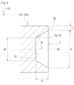
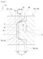
- FIG. FIG. 2 is a schematic cross-sectional view showing the II-II cross section of FIG. 3 is a schematic partial cross-sectional view showing an enlarged first end portion of the first middle core portion, a second end portion of the second middle core portion, and a gap portion in the cross section shown in FIG. 4 is a schematic partial cross-sectional view showing an enlarged view of only the first end portion of the first middle core portion shown in FIG. 3.
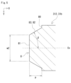
- FIG. 5 is a schematic partial cross-sectional view showing an enlarged view of only the second end portion of the second middle core portion shown in FIG. 3.
- Inductance When the magnetic core is magnetically saturated, the inductance drops. A gap is provided in the magnetic core to suppress magnetic saturation of the magnetic core. Inductance varies with the magnetic permeability of the entire magnetic core. The magnetic permeability of the magnetic core varies depending on the length and area of the gap, that is, the volume of the gap. In order to obtain a predetermined inductance, it is necessary to adjust the volume of the gap portion.
- One object of the present disclosure is to provide a reactor in which the volume of the gap portion can be easily adjusted. Another object of the present disclosure is to provide a converter including the reactor. Furthermore, another object of the present disclosure is to provide a power converter including the above converter.
- the reactor of the present disclosure facilitates adjustment of the volume of the gap. Also, the converter and the power conversion device of the present disclosure include a reactor having stable inductance characteristics.
- a reactor is A coil having a winding portion and a magnetic core having a middle core portion, The winding portion is arranged on the middle core portion, The middle core part is a first middle core portion and a second middle core portion divided in the axial direction of the winding portion; a gap portion provided between the first middle core portion and the second middle core portion; The first middle core portion has a first end facing the second middle core portion, The second middle core portion has a second end facing the first middle core portion, the first end has a recess opening toward the second middle core portion and an annular first surface through which the recess opens; The second end has a convex portion fitted in the concave portion, and an annular second surface facing the first surface with a gap in the axial direction, The recess is formed to become smaller as it moves away from the first surface, the bottom surface of the concave portion faces the top surface of the convex portion with a gap in the axial direction; the inner peripheral surface of the recess includes an inclined surface
- the reactor of the present disclosure it is easy to adjust the volume of the gap portion by the first gap portion and the second gap portion.
- a predetermined inductance is obtained by adjusting the volume of the gap portion to a predetermined volume.
- the middle core portion has a gap portion, the magnetic core is less likely to be magnetically saturated. Therefore, the reactor of the present disclosure has stable inductance characteristics.
- the concave portion formed at the first end of the first middle core portion and the convex portion formed at the second end portion of the second middle core portion are fitted to each other, whereby the middle core portion A first gap portion and a second gap portion are formed in.
- the convex portion is positioned with respect to the concave portion because the inclined surface on the inner peripheral surface of the concave portion has a contact portion in contact with the convex portion. Thereby, the length of the first gap portion and the length of the second gap portion are maintained.
- the first middle core portion and the second middle core portion are connected by fitting the concave portion of the first middle core portion and the convex portion of the second middle core portion.
- the reactor of the present disclosure is also excellent in assembling workability of the magnetic core.
- Each of the first middle core portion and the second middle core portion may be composed of a compact made of a composite material in which soft magnetic powder is dispersed in a resin.
- the composite material compact has a relatively low relative magnetic permeability, it is difficult for magnetic saturation to occur.
- the magnetic saturation of the magnetic core is more likely to be suppressed.
- a maximum length of the first gap portion may be 0.3 mm or more and 3 mm or less.
- a maximum length of the second gap portion may be 0.3 mm or more and 3 mm or less.
- An inclination angle ⁇ of the inclined surface of the recess may be 30° or more and 60° or less.
- the convex portion may be formed so as to become smaller with increasing distance from the second surface.
- the outer peripheral surface of the convex portion includes an inclined surface inclined along the inclined surface of the concave portion; In the contact portion, the inclined surface of the concave portion and the inclined surface of the convex portion may be in surface contact.
- the surface contact between the concave portion and the convex portion improves the positioning accuracy of the convex portion with respect to the concave portion.
- the configuration of (7) above can improve the positioning accuracy of the convex portion with respect to the concave portion.
- the inclination angle ⁇ of the outer peripheral surface of the convex portion is smaller than the inclination angle ⁇ of the inclined surface of the concave portion;
- the inclined surface of the concave portion and the peripheral edge portion of the top surface of the convex portion may be in line contact.
- the line contact between the concave portion and the convex portion increases the non-contact area between the concave portion and the convex portion compared to the case where the concave portion and the convex portion are in surface contact. That is, since the volume of the gap portion is increased, the inductance characteristic is improved.
- Each of a Young's modulus of the first middle core portion and a Young's modulus of the second middle core portion may be 20 GPa or more and 50 GPa or less.
- a Young's modulus of the first middle core portion may be equal to a Young's modulus of the second middle core portion.
- a difference between a Young's modulus of the first middle core portion and a Young's modulus of the second middle core portion may be 5 GPa or more and 30 GPa or less.
- the magnetic core may be composed of a first core and a second core.
- the first core has the first middle core portion
- the second core may have the second middle core portion.
- the configuration of (13) above is excellent in assembling workability of the magnetic core.
- the first core and the second core are connected by fitting the concave portion of the first middle core portion with the convex portion of the second middle core portion.
- the first core and the second core can be easily assembled by fitting the concave portion and the convex portion, and the first core and the second core can be positioned.
- the power conversion device of the present disclosure includes the converter of the present disclosure, it includes a reactor having stable inductance characteristics.
- the second end portion 312 of the second middle core portion 31b has a convex portion 8 and a second surface 80.
- the gap portion 3g is formed by fitting the convex portion 8 into the concave portion 7.
- the coil 2 has windings 20 as shown in FIG.
- the winding portion 20 is a portion where the winding is spirally wound.
- a known winding can be used for the winding.
- the winding is a coated rectangular wire having a conductor wire and an insulating coating covering the conductor wire.
- the conductor wire is a rectangular wire made of copper.
- the insulating coating is made of enamel.
- the number of winding parts 20 in this embodiment is one.
- the number of turns of the wound portion 20 is, for example, 10 turns or more and 60 turns or less, and further 20 turns or more and 50 turns or less.
- the coil 2 is an edgewise coil formed by edgewise winding a covered rectangular wire.
- the shape of the winding part 20 is cylindrical.
- the shape of the winding portion 20 may be a polygonal tubular shape or a cylindrical shape.
- a polygonal cylindrical shape means that the contour shape of the end surface of the wound portion 20 as seen from the axial direction is polygonal.
- a polygonal shape is, for example, a quadrangular shape, a hexagonal shape, or an octagonal shape.
- a square shape includes a rectangular shape.
- a rectangular shape includes a square shape.
- the term “cylindrical” means that the contour shape of the end face is circular.
- the circular shape includes not only a true circular shape but also an elliptical shape.
- the shape of the winding portion 20 is a rectangular tube.
- the coil 2 has a terminal portion 21.
- the terminal portions 21 are portions from which the windings are drawn out from both ends of the winding portion 20 .
- the terminal portion 21 has a first terminal portion 21a and a second terminal portion 21b.
- the first terminal portion 21 a is pulled out from one end of the winding portion 20 to the outer peripheral side of the winding portion 20 .
- the second terminal portion 21 b is pulled out from the other end of the winding portion 20 to the outer peripheral side of the winding portion 20 .
- the insulating coating is peeled off to expose the conductor wire.
- a bus bar (not shown) is connected to the first terminal portion 21a and the second terminal portion 21b.
- the coil 2 is connected to an external device (not shown) via a busbar.
- the external device is, for example, a power source that supplies power to the coil 2 .
- the magnetic core 3 has a middle core portion 31, a side core portion 33, and an end core portion 35, as shown in FIGS.
- the magnetic core 3 is configured in a ⁇ shape as a whole in a plan view.
- a ⁇ -shaped closed magnetic circuit is formed in the magnetic core 3 .
- This closed magnetic path is a closed magnetic path in which the magnetic flux generated by the coil 2 passes from the middle core portion 31 through one end core portion 35 , each side core portion 33 , the other end core portion 35 , and returns to the middle core portion 31 .
- the magnetic core 3 includes a first core 3a and a second core 3b.
- the magnetic core 3 is configured by combining a first core 3a and a second core 3b.
- the first core 3 a and the second core 3 b are combined in the axial direction of the winding portion 20 .
- the first core 3a and the second core 3b will be described later.
- the direction along the axial direction of the winding portion 20 is the X direction.
- the direction in which the middle core portion 31 and the side core portion 33 are arranged in parallel is defined as the Y direction.
- the Y direction is orthogonal to the X direction.
- a direction orthogonal to both the X direction and the Y direction is defined as the Z direction.
- the side where the end portion 21 of the coil 2 is located is the upper side, and the opposite side is the lower side.
- the planar view described above refers to a state in which the reactor 1a is viewed from above, that is, from the Z direction.
- FIG. 2 shows a cross section of the reactor 1a cut along the XY plane perpendicular to the Z direction at the center position of the middle core portion 31 in the Z direction.
- two-dot chain lines indicate the boundary between the middle core portion 31 and the end core portion 35 and the boundary between the side core portion 33 and the end core portion 35 .
- Middle core portion 31 has a portion arranged inside winding portion 20 .
- the number of middle core portions 31 in this embodiment is one.
- the middle core portion 31 is a portion of the magnetic core 3 sandwiched between the first end core portion 35a and the second end core portion 35b.
- the first end core portion 35a and the second end core portion 35b will be described later.
- the middle core portion 31 extends along the X direction.
- the axial direction of the middle core portion 31 coincides with the axial direction of the winding portion 20 .
- both ends of the middle core portion 31 protrude from both end surfaces of the wound portion 20 . This projecting portion is also part of the middle core portion 31 .
- the shape of the middle core portion 31 is not particularly limited as long as it corresponds to the inner shape of the winding portion 20 .
- the shape of the middle core portion 31 is substantially rectangular parallelepiped.
- the corners of the outer peripheral surface of the middle core portion 31 may be rounded along the inner peripheral surface of the wound portion 20 when viewed from the X direction.
- the middle core portion 31 is divided in the X direction and has a first middle core portion 31a and a second middle core portion 31b.
- the end face of the first middle core portion 31a and the end face of the second middle core portion 31b face each other in the X direction.
- the first middle core portion 31a is positioned on one side in the X direction where the first core 3a is arranged.
- One side in the X direction is the left side of the paper surface in FIG.
- the second middle core portion 31b is positioned on the other side in the X direction where the second core 3b is arranged.
- the other side in the X direction is the right side of the paper surface in FIG.
- the lengths of the first middle core portion 31a and the second middle core portion 31b may be appropriately set.
- the length here refers to the length along the X direction.
- the length of the first middle core portion 31a is the distance from the boundary between the first middle core portion 31a and the first end core portion 35a to the farthest point in the X direction.
- the length of the first middle core portion 31a is the length including the recess 7 and is the distance along the X direction from the boundary to the first surface 70 (see also FIG. 3).
- the length of the second middle core portion 31b is the distance from the boundary between the second middle core portion 31b and the second end core portion 35b to the furthest point in the X direction.
- the dimensions in the Y direction and the Z direction of the end surface of the first middle core portion 31 a are dimensions including the first surface 70 .
- the Y-direction dimension of the second middle core portion 31b is the same as the Y-direction dimension of the first middle core portion 31a.
- the Z-direction dimension of the second middle core portion 31b is the same as the Z-direction dimension of the first middle core portion 31a.
- the dimensions in the Y direction and the Z direction of the end surface of the second middle core portion 31b are dimensions including the second surface 80 .
- the middle core portion 31 has a gap portion 3g.
- the gap portion 3g is provided between the first middle core portion 31a and the second middle core portion 31b.
- Gap portion 3 g is positioned inside winding portion 20 . Positioning the gap portion 3g inside the winding portion 20 reduces leakage magnetic flux from the gap portion 3g as compared with the case where the gap portion 3g is positioned outside the winding portion 20 . Therefore, it is possible to reduce the loss caused by the leakage magnetic flux from the gap portion 3g. Details of the gap portion 3g will be described later.
- the first end portion 311 of the first middle core portion 31a has the recess 7 and the first surface .
- the first end portion 311 faces the second middle core portion 31b as shown in FIG.
- the recess 7 opens toward the second middle core portion 31b.
- the first surface 70 is an annular surface in which the recess 7 opens.
- the first surface 70 is annularly provided so as to surround the opening of the recess 7 .
- 3 and 4 show XY cross sections perpendicular to the Z direction. Although not shown, the XZ cross section perpendicular to the Y direction is also the same as in FIGS. 3 and 4, the first surface 70 also exists on the upper and lower sides in the Z direction.
- the upper side in the Z direction is the front side of the plane of FIGS. 3 and 4 .
- the lower side in the Z direction is the back side of the paper surface of FIGS. 3 and 4 .
- the recess 7 has a bottom surface 71 and an inner peripheral surface 72 .
- the bottom surface 71 faces the top surface 81 of the projection 8 when the projection 8 is fitted in the recess 7 as shown in FIG.
- the convex portion 8 will be described later.
- the bottom surface 71 and the top surface 81 are spaced apart in the X direction.
- the bottom surface 71 and the top surface 81 are non-contact.
- the inner peripheral surface 72 connects the first surface 70 and the bottom surface 71 .
- the inner peripheral surface 72 includes an inclined surface 73 .
- An extension surface of the inclined surface 73 intersects the axis Cx along the X direction.
- the inclined surface 73 has a contact portion 75 .
- the contact portion 75 contacts the convex portion 8 .
- the concave portion 7 is formed so as to become smaller with increasing distance from the first surface 70 . That is, the recess 7 has a tapered shape in which the interval of the inner peripheral surface 72 narrows from the opening of the recess 7 toward the bottom surface 71 .
- the shape of the recess 7 is not particularly limited.
- the shape of the recess 7 refers to the shape of the space surrounded by the bottom surface 71 and the inner peripheral surface 72 .
- the shape of the concave portion 7 may be, for example, a polygonal truncated pyramid shape or a truncated cone shape.
- the truncated polygonal pyramid shape means that the cross-sectional shape of the YZ cross section orthogonal to the X direction is polygonal, and the cross-sectional shapes of the XY cross section and the XZ cross section are trapezoidal.
- a polygonal shape is, for example, a quadrangular shape, a hexagonal shape, or an octagonal shape.
- a square shape includes a rectangular shape.
- a rectangular shape includes a square shape.
- the truncated cone shape means that the cross-sectional shape of the YZ cross section is circular, and the cross-sectional shapes of the XY cross section and the XZ cross section are trapezoidal.
- the circular shape includes not only a true circular shape but also an elliptical shape.
- the shape of the concave portion 7 is a truncated quadrangular pyramid.
- the contour shape of the opening of the recess 7 is a rectangular shape similar to the contour shape of the end face of the first middle core portion 31a.
- the shape of the bottom surface 71 is rectangular.
- the bottom surface 71 is a plane perpendicular to the X direction.
- the inner peripheral surface 72 of this embodiment is formed as an inclined surface 73 over the entire length from the first surface 70 to the bottom surface 71 .
- the inclined surface 73 does not have to be provided over the entire length of the inner peripheral surface 72 .
- the inclined surface 73 may be provided in a partial region of the entire length of the inner peripheral surface 72 .
- the inclined surface 73 may be provided only in a part of the inner peripheral surface 72 on the side of the first surface 70 .
- the bottom surface 71 may be formed in a U-shape or a V-shape instead of being flat in the XY cross section or the XZ cross section.
- the bottom surface 71 is located in a direction away from the first surface 70 from the contact portion 75 shown in FIG.
- the position of the bottom surface 71 in the X direction includes the position of the contact portion 75 , and may be at the same position as the contact portion 75 or at a position away from the contact portion 75 .
- the bottom surface 71 and the contact portion 75 are at the same position in the X direction as shown in FIG.
- the bottom surface 71 when the bottom surface 71 is formed in a V shape such that the concave portion 7 has a polygonal pyramid shape or a conical shape, the bottom surface 71 is positioned distally from the first surface 70 relative to the contact portion 75. and When the bottom surface 71 is formed in a U shape, the bottom surface 71 is a curved surface.
- the first surface 70 is formed in an annular shape when viewed from the side where the recess 7 opens.
- the first surface 70 has a shape corresponding to the contour shape of the end face of the first middle core portion 31a.
- the shape of the first surface 70 is a rectangular ring.
- the width of the first surface 70 is, for example, 0.5 mm or more and 5 mm or less, and further 1 mm or more and 2 mm or less.
- the width of the first surface 70 is the distance from the inner peripheral edge of the opening to the outer peripheral edge of the first surface 70 .
- the first surface 70 of this embodiment is a plane perpendicular to the X direction.
- the first surface 70 may be an inclined surface that is inclined with respect to a plane perpendicular to the X direction.
- the second end portion 312 of the second middle core portion 31b has a convex portion 8 and a second surface 80.
- the second end portion 312 faces the first middle core portion 31a as shown in FIG.
- the convex portion 8 protrudes toward the first middle core portion 31a.
- the protrusion 8 is fitted with the recess 7 .
- the second surface 80 is an annular surface facing the first surface 70 .
- the second surface 80 is annularly provided so as to surround the convex portion 8 .
- the first surface 70 and the second surface 80 are spaced apart in the X direction.
- the first surface 70 and the second surface 80 are non-contact.
- FIG. 5 shows an XY section perpendicular to the Z direction.
- the XZ cross section perpendicular to the Y direction is also the same as in FIG. 3 and 5
- the second surface 80 also exists on the upper and lower sides in the Z direction.
- the upper side in the Z direction is the front side of the plane of FIGS. 3 and 5 .
- the lower side in the Z direction is the back side of the paper surface of FIGS. 3 and 5 .
- the protrusion 8 has a top surface 81 and an outer peripheral surface 82 .
- the top surface 81 faces the bottom surface 71 of the recess 7 when the protrusion 8 is fitted in the recess 7 as shown in FIG.
- the outer peripheral surface 82 connects the second surface 80 and the top surface 81 .
- the outer peripheral surface 82 includes an inclined surface 83 .
- An extension surface of the inclined surface 83 intersects the axis Cx along the X direction.
- the shape of the convex portion 8 is not particularly limited as long as the convex portion 8 is in contact with the inclined surface 73 when the convex portion 8 is fitted in the concave portion 7 .
- the convex portion 8 is formed so as to become smaller with distance from the second surface 80 . That is, the convex portion 8 has a tapered shape in which the interval of the outer peripheral surface 82 narrows from the second surface 80 toward the top surface 81 .
- the shape of the convex portion 8 may be, for example, a polygonal truncated pyramid shape or a truncated cone shape.
- the shape of the convex portion 8 is a shape corresponding to the shape of the concave portion 7 .
- the shape of the convex portion 8 is a truncated quadrangular pyramid.
- the shape of the top surface 81 is rectangular.
- the top surface 81 is a plane perpendicular to the X direction.
- the outer peripheral surface 82 of this embodiment is formed as an inclined surface 83 over the entire length from the second surface 80 to the top surface 81 .
- the inclined surface 83 may not be provided over the entire length of the outer peripheral surface 82 .
- the inclined surface 83 may be provided in a partial region of the entire length of the outer peripheral surface 82 .
- the inclined surface 83 may be provided only in a part of the outer peripheral surface 82 on the top surface 81 side.
- the shape of the area of the convex portion 8 on the side opposite to the top surface 81 side is, for example, a polygonal prism shape.
- the top surface 81 may be formed in a U-shape or a V-shape instead of a plane in the XY cross section or the XZ cross section.
- the top surface 81 is located in a direction away from the second surface 80 from the contact portion 75 shown in FIG.
- the position of the top surface 81 in the X direction includes the position of the contact portion 75 , and may be at the same position as the contact portion 75 or at a position away from the contact portion 75 .
- the top surface 81 and the contact portion 75 are at the same position in the X direction.
- the top surface 81 when the top surface 81 is formed in a V shape such that the convex portion 8 has a polygonal pyramid shape or a conical shape, the top surface 81 extends from the second surface 80 to the distal side of the contact portion 75. The place where it is located.
- the top surface 81 is defined as a curved surface.
- the second surface 80 is formed in an annular shape when viewed from the top surface 81 side of the convex portion 8 .
- the second surface 80 has a shape corresponding to the contour shape of the end surface of the second middle core portion 31b.
- the shape of the second surface 80 is a rectangular ring.
- the width of the second surface 80 is, for example, 0.5 mm or more and 5 mm or less, and further 1 mm or more and 2 mm or less.
- the width of the second surface 80 is the distance from the inner peripheral edge of the second surface 80 to the outer peripheral edge.
- the second surface 80 of this embodiment is a plane perpendicular to the X direction.
- the second surface 80 may be an inclined surface that is inclined with respect to a plane perpendicular to the X direction.
- the gap portion 3g is formed by fitting the concave portion 7 and the convex portion 8 as shown in FIG.
- the gap portion 3g has a first gap portion 31g and a second gap portion 32g.
- the first gap portion 31 g is formed between the bottom surface 71 and the top surface 81 .
- the second gap portion 32g is formed between the first surface 70 and the second surface 80. As shown in FIG. In FIG. 3, the second gap portion 32g also exists on the upper and lower sides in the Z direction.
- the second gap portion 32g has an annular shape when viewed from the X direction.
- the size of each of the first gap portion 31g and the second gap portion 32g may be appropriately set so as to obtain a predetermined inductance.
- the maximum length g1 of the first gap portion 31g is, for example, 0.3 mm or more and 3 mm or less.
- a maximum length g1 is the distance along the X direction between the bottom surface 71 and the top surface 81 . Magnetic saturation of the magnetic core 3 is easily suppressed when the maximum length g1 is 0.3 mm or more.
- the maximum length g1 is 3 mm or less, it is easy to suppress excessive decrease in magnetic permeability of the magnetic core 3 . Therefore, it is easy to secure good inductance.
- the maximum length g1 is 3 mm or less, it is easy to suppress leakage magnetic flux from the first gap portion 31g.
- the maximum length g1 may also be 1.5 mm or less. If the maximum length g1 is 1.5 mm or less, it is easier to suppress leakage magnetic flux.
- the maximum length g2 of the second gap portion 32g is, for example, 0.3 mm or more and 3 mm or less.
- a maximum length g2 is the distance along the X direction between the first surface 70 and the second surface 80 .
- Magnetic saturation of the magnetic core 3 can be easily suppressed when the maximum length g2 is 0.3 mm or more.
- the maximum length g2 is 3 mm or less, it is easy to suppress excessive decrease in magnetic permeability of the magnetic core 3 . Therefore, it is easy to secure good inductance.
- the maximum length g2 is 3 mm or less, it is easy to suppress leakage magnetic flux from the second gap portion 32g.
- the maximum length g2 may also be 1.5 mm or less. If the maximum length g2 is 1.5 mm or less, it is easier to suppress leakage magnetic flux.
- the first gap portion 31g and the second gap portion 32g may be air gaps.
- a non-magnetic material such as resin or ceramics may be disposed in the first gap portion 31g and the second gap portion 32g.
- one gap portion 3g may have a region formed of space and a region formed of resin.
- the dimensions of the concave portion 7 and the inclination angle ⁇ of the inclined surface 73, the dimensions of the convex portion 8 and the inclination angle ⁇ of the inclined surface 83 are appropriately determined so that each of the first gap portion 31g and the second gap portion 32g has a predetermined size. You can set it.
- the width a of the opening of the recess 7 may be appropriately set according to the dimension of the end face of the first middle core portion 31a.
- the width a is the maximum dimension of the opening.
- the dimension of the aperture is the dimension in the Y direction or the dimension in the Z direction.
- the width a is, for example, 5 mm or more and 59 mm or less, and further 20 mm or more and 30 mm or less.
- the width w1 of the bottom surface 71 is smaller than the width a of the opening.
- the width w1 is, for example, 4 mm or more and 58 mm or less, and further 19 mm or more and 29 mm or less.
- the width w1 is the maximum dimension of the bottom surface 71 .
- the dimension of the bottom surface 71 is the dimension in the Y direction or the dimension in the Z direction.
- the depth d of the concave portion 7 is, for example, 1 mm or more and 10 mm or less, and further 2 mm or more and 4 mm or less.
- the depth d is the distance along the X direction between the inner peripheral edge of the opening and the bottom surface 71 .
- the thickness t of the wall forming the recess 7 is, for example, 0.5 mm or more and 5 mm or less, and further 1 mm or more and 2 mm or less.
- the thickness t is the distance from the inner peripheral surface 72 to the outer peripheral surface of the first end portion 311 .
- the inclination angle ⁇ of the inclined surface 73 is, for example, 30° or more and 60° or less.
- the inclination angle ⁇ is the smaller angle between the axis Cx and the extension surface of the inclined surface 73 . Since the inclination angle ⁇ is within the above range, it is easy to obtain the first gap portion 31g having a predetermined size.
- the inclination angle ⁇ may be 40° or more and 50° or less.
- the dimensions of the convex portion 8 are the same as those of the concave portion 7 so that the first gap portion 31g and the second gap portion 32g are formed when the concave portion 7 and the convex portion 8 are fitted together as shown in FIG. It may be set as appropriate.
- the width w2 of the top surface 81 is smaller than the width a of the opening of the recess 7 and larger than the width w1 of the bottom surface 71 .
- the width w2 is, for example, 4.5 mm or more and 58.5 mm or less, and further 19.5 mm or more and 29.5 mm or less.
- Width w2 is the maximum dimension of top surface 81 .
- the dimension of the top surface 81 is the dimension in the Y direction or the dimension in the Z direction.
- the height p of the convex portion 8 is, for example, 1 mm or more and 10 mm or less, and further 2 mm or more and 5 mm or less. Height p is the distance along the X direction between the second surface 80 and the top surface 81 .
- the inclination angle ⁇ of the inclined surface 83 is, for example, 30° or more and 60° or less.
- the inclination angle ⁇ is the smaller angle between the axis Cx and the extension surface of the inclined surface 83 . Since the inclination angle ⁇ is within the above range, it is easy to obtain the first gap portion 31g having a predetermined size.
- the inclination angle ⁇ may be 40° or more and 50° or less.
- the inclination angle ⁇ of the inclined surface 83 is the same as the inclination angle ⁇ of the inclined surface 73 . Therefore, the inclined surface 73 and the inclined surface 83 are in surface contact at the contact portion 75 .
- the surface contact between the inclined surface 73 and the inclined surface 83 improves the positioning accuracy of the convex portion 8 with respect to the concave portion 7 .
- the length s of the contact portion 75 along the inclined surface 73 is, for example, 0.5 mm or more and 5 mm or less.
- the length s is hereinafter referred to as the contact length s.
- the contact length s is the length along the direction of inclination of the inclined surfaces 73 and 83 where the inclined surfaces 73 and 83 are in contact with each other.
- the contact length s may be 0.5 mm or more and 3 mm or less, or 0.6 mm or more and 1 mm or less.
- the contact portion 75 of this embodiment exists over the entire circumference of the inner peripheral surface 72 of the concave portion 7 and the outer peripheral surface 82 of the convex portion 8 .
- the length f of the convex portion 8 fitted into the concave portion 7 may be appropriately set so that the first gap portion 31g and the second gap portion 32g are formed.
- the length f will be referred to as the fitting length f.
- the fitting length f is the distance along the X direction from the first surface 70 to the top surface 81 .
- the fitting length f is smaller than the depth d of the concave portion 7 and smaller than the height p of the convex portion 8 .
- the fitting length f is, for example, 0.5 mm or more and 5 mm or less.
- the fitting length f may be 0.5 mm or more and 3 mm or less, or 0.6 mm or more and 1 mm or less.
- the end core portion 35 is a portion arranged outside the winding portion 20 as shown in FIGS. 1 and 2 .
- the number of end core portions 35 is two.
- the two end core portions 35 are spaced apart in the X direction.
- the end core portion 35 has a first end core portion 35a and a second end core portion 35b.
- the first end core portion 35a is located on one side in the X direction.
- the first end core portion 35 a faces one end surface of the winding portion 20 .
- One end of the middle core portion 31 in the X direction, specifically, the end of the first middle core portion 31a is connected to the first end core portion 35a.
- the second end core portion 35b is located on the other side in the X direction.
- the second end core portion 35b faces the other end face of the winding portion 20. As shown in FIG.
- the other end of the middle core portion 31 in the X direction, the end of the second middle core portion 31b is connected to the second end core portion 35b.
- each of the first end core portion 35a and the second end core portion 35b is not particularly limited as long as it forms a predetermined magnetic path.
- the shape of each of the first end core portion 35a and the second end core portion 35b is substantially rectangular parallelepiped.
- the side core portion 33 is a portion arranged outside the winding portion 20 as shown in FIGS. 1 and 2 .
- the number of side core portions 33 is two.
- the two side core portions 33 are spaced apart in the Y direction.
- the two side core portions 33 are arranged in parallel so as to sandwich the middle core portion 31 . That is, the middle core portion 31 is arranged between the two side core portions 33 .
- One side core portion 33 is positioned on one side in the Y direction.
- One side core portion 33 faces one side surface in the Y direction of the outer peripheral surface of the winding portion 20 .
- One side in the Y direction is the upper side of the paper surface in FIG.
- the other side core portion 33 is positioned on the other side in the Y direction.
- the other side core portion 33 faces the side surface on the other side in the Y direction of the outer peripheral surface of the winding portion 20 .
- the other side in the Y direction is the lower side of the paper in FIG.
- Each of the side core portions 33 extends in the X direction.
- the axial direction of each side core portion 33 is parallel to the axial direction of the middle core portion 31 .
- One end of the side core portion 33 in the X direction is connected to the first end core portion 35a.
- the end of the side core portion 33 on the other side in the X direction is connected to the second end core portion 35b.
- Each cross-sectional area of the side core portions 33 may be the same or different.
- the cross-sectional areas of the two side core portions 33 are the same.
- the total cross-sectional area of the two side core portions 33 is the same as the cross-sectional area of the middle core portion 31 .
- the total cross-sectional area of the two side core portions 33 may differ from the cross-sectional area of the middle core portion 31 .
- the cross-sectional area here refers to the area of a cross section orthogonal to the X direction.
- Each of the side core portions 33 should have a length that connects the first end core portion 35a and the second end core portion 35b.
- the shape of the side core portion 33 is not particularly limited. In this embodiment, each side core portion 33 has a substantially rectangular parallelepiped shape.
- the first core 3a has a first middle core portion 31a.
- the second core 3b has a second middle core portion 31b.
- the shape of each of the first core 3a and the second core 3b can be selected from various combinations.
- the magnetic core 3 is an ET type in which an E-shaped first core 3a and a T-shaped second core 3b are combined.
- the first core 3a has a first middle core portion 31a, a first end core portion 35a, and two side core portions 33. As shown in FIG.
- the first middle core portion 31a, the first end core portion 35a, and the two side core portions 33 are integrally molded. Since the first core 3a is an integral molded body, each core portion constituting the first core 3a is made of the same material. That is, the magnetic properties and mechanical properties of the respective core portions forming the first core 3a are substantially the same.
- the first middle core portion 31a extends in the X direction from the middle portion of the first end core portion 35a in the Y direction toward the second middle core portion 31b.
- Each of the side core portions 33 extends in the X direction from both ends of the first end core portion 35a in the Y direction toward the second end core portion 35b.
- the shape of the first core 3a is an E shape when viewed from the Z direction.
- the second core 3b has a second middle core portion 31b and a second end core portion 35b.
- the second middle core portion 31b and the second end core portion 35b are integrally molded. Since the second core 3b is an integral molded body, each core portion constituting the second core 3b is made of the same material. That is, the magnetic properties and mechanical properties of the respective core portions forming the second core 3b are substantially the same.
- the second middle core portion 31b extends in the X direction from the middle portion of the second end core portion 35b in the Y direction toward the first middle core portion 31a.
- the shape of the second core 3b is T-shaped when viewed from the Z direction.
- the first core 3a and the second core 3b have a concave portion 7 formed at a first end portion 311 of the first middle core portion 31a and a convex portion formed at a second end portion 312 of the second middle core portion 31b. 8 are fitted to be connected.
- the magnetic core 3 is composed of two pieces, a first core 3a and a second core 3b. That is, the number of divisions of the magnetic core 3 is two.
- the number of divisions of the magnetic core 3 and the positions at which the magnetic core 3 is divided are not particularly limited.
- the magnetic core 3 may be composed of three or more pieces.
- the first end core portion 35a, the second end core portion 35b, the first middle core portion 31a, the second middle core portion 31b, and the two side core portions 33 are individually configured, and the magnetic core 3 is configured by combining these.
- the number of core pieces to be combined is only two, so the magnetic core 3 can be easily assembled.
- the first core 3a and the second core 3b are made of molded soft magnetic material.
- the shaped bodies are, for example, compacts or composite shaped bodies.
- the powder compact is formed by compression molding raw material powder containing soft magnetic powder.
- the compacted body has a larger content of soft magnetic powder than the compacted body of the composite material. Therefore, the powder compact has higher magnetic properties than the composite material compact. Magnetic properties are, for example, relative magnetic permeability and saturation magnetic flux density.
- the powder compact may contain, for example, at least one of a binder resin and a molding aid.
- the content of the soft magnetic powder in the powder compact is, for example, more than 85% by volume and 99.99% by volume or less when the compact is 100% by volume.
- Composite molded bodies are made by dispersing soft magnetic powder in resin.
- a molded body of composite material is obtained by filling a mold with a fluid material in which soft magnetic powder is dispersed in unsolidified resin and solidifying the resin.
- a method of molding the composite material can utilize, for example, injection molding or cast molding.
- the soft magnetic powder content of the composite material compact can be easily adjusted. Therefore, it is easy to adjust the magnetic properties of the molded body of the composite material.
- the content of the soft magnetic powder in the composite material compact is, for example, 20% by volume or more and 85% by volume or less, further 30% by volume or more and 80% by volume or less, when the composite material compact is 100% by volume.
- the content of the resin in the molded body of the composite material is, for example, 20% by volume or more and 80% by volume or less, and further 20% by volume or more and 70% by volume or less.
- the content of the soft magnetic powder in the compact of the composite material is less than the content of the soft magnetic powder in the compact. Therefore, the relative magnetic permeability of the molded body of the composite material is smaller than that of the compacted body.
- the particles that make up the soft magnetic powder are at least one selected from soft magnetic metal particles, soft magnetic metal particles with an insulating coating on the outer circumference of the soft magnetic metal particles, and soft magnetic non-metal particles.
- a soft magnetic metal is, for example, pure iron or an iron-based alloy.
- the iron-based alloy is, for example, Fe (iron)--Si (silicon) alloy, Fe--Ni (nickel) alloy, or Fe--Si--Al (aluminum) alloy.
- the insulating coating is, for example, phosphate.
- a soft magnetic non-metal is, for example, ferrite.
- the resin of the molded composite material may be either a thermosetting resin or a thermoplastic resin.
- Thermosetting resins are, for example, unsaturated polyester resins, epoxy resins, urethane resins, or silicone resins.
- the thermoplastic resin is, for example, polyphenylene sulfide resin, polytetrafluoroethylene resin, liquid crystal polymer, polyamide resin, polybutylene terephthalate resin, or acrylonitrile-butadiene-styrene resin.
- Polyamide resins are, for example, nylon 6, nylon 66, or nylon 9T.
- the resin of the molded composite material may be, for example, BMC (Bulk molding compound), millable silicone rubber, or millable urethane rubber.
- the BMC is, for example, unsaturated polyester mixed with calcium carbonate or glass fiber.
- the resin of the molded composite material may be a resin having excellent heat resistance.
- resins having excellent heat resistance are polyphenylene sulfide resins and polyamide resins including nylon.
- the molded body of the composite material may contain filler in addition to the soft magnetic powder and resin.
- the filler is, for example, a ceramic filler of alumina or silica.
- the content of the filler is, for example, 0.2% by mass or more and 20% by mass or less, further 0.3% by mass or more and 15% by mass or less, or 0.5% by mass or more and 10% by mass, when the molded article of the composite material is 100% by volume. % by mass or less.
- the content of the soft magnetic powder in the powder compact or composite material compact is considered equivalent to the area ratio of the soft magnetic powder in the cross section of the compact.
- the content of the soft magnetic powder is obtained as follows. A cross section of the compact is observed with a scanning electron microscope (SEM) to obtain an observed image. The magnification of the SEM is, for example, 200 times or more and 500 times or less. The number of acquired observation images is set to 10 or more. The total area of the observation image shall be 0.1 cm 2 or more. One observation image may be acquired for one cross section, or a plurality of observation images may be acquired for one cross section. Image processing is performed on each of the acquired observation images to extract the contours of the particles of the soft magnetic powder. Image processing is, for example, binarization processing. The total area of the particles of the soft magnetic powder is calculated in each observation image, and the area ratio of the particles of the soft magnetic powder in each observation image is obtained. The average value of the area ratios in all observed images is regarded as the content of the soft magnetic powder.
- each of the first core 3a and the second core 3b is a composite material compact.
- the relative magnetic permeability of the compact of composite material is relatively small. Therefore, since the first core 3a and the second core 3b are made of composite material, the magnetic core 3 is less likely to be magnetically saturated.
- each of the Young's modulus of the first core 3a and the Young's modulus of the second core 3b is, for example, 20 GPa or more and 50 GPa or less. That is, each of the Young's modulus of the first middle core portion 31a and the Young's modulus of the second middle core portion 31b is 20 GPa or more and 50 GPa or less.
- the concave portion 7 and the convex portion 8 are excessively formed when the concave portion 7 and the convex portion 8 are fitted. Hard to deform. Since the shapes of the concave portion 7 and the convex portion 8 are easily maintained, it is easy to secure the first gap portion 31g and the second gap portion 32g.
- the Young's modulus of the first core 3a and the Young's modulus of the second core 3b may be equal or different.
- the first core 3a and the second core 3b are made of the same material.
- the same material means that the kind and content of the soft magnetic powder and the kind and content of the resin that constitute the molded body of the composite material are the same.
- the type of soft magnetic powder is a concept that includes the size and shape of particles that constitute the soft magnetic powder.
- the particle size of the soft magnetic powder is, for example, the particle diameter of the particles.
- the shape of the particles of the soft magnetic powder is, for example, spherical or flaky.
- the same material means that the type, size and content of the filler are also the same.
- the Young's modulus of the first core 3a and the Young's modulus of the second core 3b are equal. Since the Young's modulus of the first middle core portion 31a and the Young's modulus of the second middle core portion 31b are equal, deformation of at least one of the concave portion 7 and the convex portion 8 is easily suppressed when the convex portion 8 is fitted into the concave portion 7. . Therefore, a predetermined gap portion 3g is easily ensured by the first gap portion 31g and the second gap portion 32g, so that variations in inductance can be easily reduced.
- the reactor 1a includes a resin molded member 4 as shown in FIGS.
- the resin molded member 4 is indicated by a chain double-dashed line.
- the resin mold member 4 covers at least part of the outer peripheral surface of the magnetic core 3 .
- the resin mold member 4 integrates the combined first core 3a and second core 3b.
- the resin mold member 4 integrates the coil 2 and the magnetic core 3 .
- the resin mold member 4 is filled between the inner peripheral surface of the winding portion 20 and the middle core portion 31 . Therefore, the resin molded member 4 holds the coil 2 positioned with respect to the magnetic core 3 .
- the resin molded member 4 ensures electrical insulation between the coil 2 and the magnetic core 3 .
- the resin forming the resin molded member 4 for example, the same resin as the resin of the above-described molded composite material can be used.
- the resin molded member 4 may cover the outer peripheral surface of the wound portion 20 .
- the resin mold member 4 may be formed such that at least one of the upper and lower surfaces of the wound portion 20 is exposed.
- the resin of the resin molded member 4 passes between the inner peripheral surface of the winding portion 20 and the middle core portion 31 to fill the second gap portion 32g.
- the first gap portion 31 g is not filled with the resin of the resin mold member 4 due to the contact portion 75 between the concave portion 7 and the convex portion 8 . Therefore, the first gap portion 31g is an air gap.
- (Holding member) Reactor 1a may include a holding member (not shown).
- the holding member is arranged between one end surface of the winding portion 20 and the first end core portion 35a and between the other end surface of the winding portion 20 and the second end core portion 35b.
- the holding member determines the relative positions of the coil 2 and the magnetic core 3 .
- the holding member also ensures electrical insulation between the coil 2 and the magnetic core 3 .
- the holding member can be made of, for example, the same resin as the resin of the molded composite material described above.
- the volume of the gap portion 3g can be easily adjusted by the first gap portion 31g and the second gap portion 32g.
- a predetermined inductance is obtained by adjusting the volume of the gap portion 3g to a predetermined volume.
- the middle core portion 31 has the gap portion 3g, the magnetic core 3 is less likely to be magnetically saturated. Therefore, the reactor 1a has stable inductance characteristics.
- a first gap portion 31g and a second gap portion 32g are formed in the middle core portion 31 by fitting the concave portion 7 of the first middle core portion 31a and the convex portion 8 of the second middle core portion 31b.
- the inclined surface 73 of the concave portion 7 has a contact portion 75 in contact with the convex portion 8 , so that the convex portion 8 is positioned with respect to the concave portion 7 . Since the distance between the bottom surface 71 and the top surface 81 and the distance between the first surface 70 and the second surface 80 are maintained, the length g1 of the first gap portion 31g and the length g2 of the second gap portion 32g are maintained.
- the contact portion 75 can prevent the convex portion 8 from being displaced in the Y direction and the Z direction within the concave portion 7, the first middle core portion 31a and the second middle core portion 31b are positioned. Furthermore, in Embodiment 1, the concave portion 7 and the convex portion 8 are in surface contact at the contact portion 75, so that the positioning accuracy of the convex portion 8 with respect to the concave portion 7 is improved.
- the first core 3a and the second core 3b are connected by fitting the concave portion 7 of the first middle core portion 31a and the convex portion 8 of the second middle core portion 31b.
- the first core 3a and the second core 3b can be easily assembled by fitting the concave portion 7 and the convex portion 8, and the first core 3a and the second core 3b can be positioned. Therefore, the magnetic core 3 is excellent also in assembly workability.
- Embodiment 2 The reactor of Embodiment 2 will be described with reference to FIG.
- the reactor of the second embodiment is different from the reactor 1a of the first embodiment in that the concave portion 7 and the convex portion 8 are in line contact at the contact portion 75 .
- the following description will focus on the differences from the first embodiment. Configurations similar to those of the first embodiment are denoted by the same reference numerals, and descriptions thereof are omitted.
- the inclination angle ⁇ of the outer peripheral surface 82 of the convex portion 8 is smaller than the inclination angle ⁇ of the inclined surface 73 of the concave portion 7 .
- the inclined surface 73 and the peripheral edge portion 84 of the top surface 81 are in line contact.
- Peripheral edge portion 84 includes a ridge formed by top surface 81 and outer peripheral surface 82 .
- the ridgeline is in contact with the inclined surface 73 .
- the outer peripheral surface 82 is formed on the inclined surface 83 .
- the convex portion 8 is formed to become smaller with increasing distance from the second surface 80 .
- the convex portion 8 may be formed so as to increase in size with increasing distance from the second surface 80 .
- Such a shape is called a tapered shape.
- the outer peripheral surface 82 may include the inclined surface 83 or may not include the inclined surface 83 .
- the outer peripheral surface 82 is parallel to the axis Cx. That is, the tilt angle ⁇ is zero.
- the inclination angle ⁇ is not particularly limited as long as it is smaller than the inclination angle ⁇ .
- the tilt angle ⁇ is 0° or more and less than the tilt angle ⁇ .
- the inclination angle ⁇ may be smaller than the inclination angle ⁇ by 3° or more, and may be smaller by 5° or more.
- the inclination angle ⁇ is, for example, more than 0° and 45° or less, and further 25° or less.
- the concave portion 7 and the convex portion 8 are in line contact at the contact portion 75, compared to the case where the concave portion 7 and the convex portion 8 are in surface contact as shown in FIG. As a result, the non-contact area between the concave portion 7 and the convex portion 8 increases. Since the volume of the gap portion 3g is increased, an improvement in inductance characteristics can be expected.
- the term "line contact” as used herein includes not only the case where the inclined surface 73 and the peripheral edge portion 84 are in geometrical line contact, but also a range that can be regarded as substantially line contact. If the contact length s shown in FIG. 3 is less than 0.5 mm, and even less than or equal to 0.4 mm, it is considered as line contact.
- the convex portion 8 has the tapered shape, the volume of the gap portion 3g can be increased compared to the tapered shape.
- the reactor of the third embodiment differs from the reactor 1a of the first embodiment in the Young's modulus of the first core 3a and the Young's modulus of the second core 3b. That is, the Young's modulus of the first middle core portion 31a and the Young's modulus of the second middle core portion 31b are different. Except for the difference in Young's modulus, other configurations are the same as those of the reactor 1a of the first embodiment shown in FIGS.
- the magnitude relationship between the Young's modulus of the first core 3a and the Young's modulus of the second core 3b is not particularly limited.
- the Young's modulus of the first core 3a may be higher than that of the second core 3b, or the Young's modulus of the first core 3a may be lower than that of the second core 3b.
- a core with a high Young's modulus is less likely to deform, and a core with a lower Young's modulus is more easily deformed.
- the difference between the Young's modulus of the first core 3a and the second core 3b, that is, the difference between the Young's modulus of the first middle core portion 31a and the second middle core portion 31b is, for example, 5 GPa or more and 30 GPa or less, or even 5 GPa. 20 GPa or less.
- the first method is to adjust the Young's modulus of the composite material compact by changing the particle size or content of the soft magnetic powder that constitutes the composite material compact.
- the average particle size of the soft magnetic powder in the core with high Young's modulus is made smaller than the average particle size of the soft magnetic powder in the core with low Young's modulus.
- the average particle size of the soft magnetic powder in the core with a high Young's modulus and the average particle size of the soft magnetic powder in the core with a low Young's modulus may be appropriately set so that the Young's modulus of each core has a predetermined value.
- the average particle size of the soft magnetic powder in the core having a high Young's modulus is, for example, 20 ⁇ m or more and 100 ⁇ m or less, and further 50 ⁇ m or more and 70 ⁇ m or less.
- the average particle size of the soft magnetic powder in the core with a low Young's modulus is, for example, 80 ⁇ m or more and 200 ⁇ m or less, and further 100 ⁇ m or more and 150 ⁇ m or less.
- the average particle size of the soft magnetic powder in the compact of the composite material is obtained as follows.
- An observed image is obtained by observing a cross section of the molded article with an SEM.
- the magnification of the SEM is, for example, 200 times or more and 500 times or less.
- the number of acquired observation images is set to 10 or more.
- One observation image may be acquired for one cross section, or a plurality of observation images may be acquired for one cross section.
- Image processing is performed on each of the acquired observation images to extract the contours of the particles of the soft magnetic powder.
- Image processing is, for example, binarization processing.
- the particle size of all particles of the soft magnetic powder is measured in each observation image.
- the particle size of each particle is the diameter of a circle having an area equal to that of each particle.
- the average particle size of the particles in all observed images is regarded as the average particle size of the soft magnetic powder.
- the content of the soft magnetic powder in the core with a high Young's modulus is made larger than the content of the soft magnetic powder in the core with a low Young's modulus.
- the content of the soft magnetic powder in the core having a high Young's modulus is, for example, 60% by volume or more and 85% by volume or less, and further 70% by volume or more and 80% by volume or less.
- the content of the soft magnetic powder in the core having a low Young's modulus is, for example, 20% by volume or more and 78% by volume or less, and further 30% by volume or more and 75% by volume or less.
- the second method is to adjust the Young's modulus of the composite material compact by changing the type of soft magnetic powder.
- the higher the Young's modulus of the soft magnetic powder the higher the Young's modulus of the composite material compact.
- the Young's modulus of the composite material compact is increased.
- the Young's modulus of the soft magnetic powder in the core with high Young's modulus is made higher than the Young's modulus of the soft magnetic powder in the core with low Young's modulus.
- the type of soft magnetic powder in the core with a high Young's modulus is, for example, an iron-based alloy powder.
- Specific examples of iron-based alloys with high Young's modulus are amorphous Fe alloys and Fe--Si--Al alloys.
- the type of soft magnetic powder in the core with a low Young's modulus is, for example, pure iron powder.
- the third method is to adjust the Young's modulus of the composite material molding by changing the resin type or resin grade.
- the higher the Young's modulus of the resin the higher the Young's modulus of the molded composite material.
- By selecting a resin having a high Young's modulus the Young's modulus of the molded composite material is increased.
- the Young's modulus of the resin in the core with a high Young's modulus is made higher than the Young's modulus of the resin in the core with a low Young's modulus.
- the type of resin in the core with high Young's modulus and the type of resin in the core with low Young's modulus may be the same or different. When the resin types are the same, a resin with a high Young's modulus grade is selected for the core with a high Young's modulus, and a resin with a low Young's modulus is selected for the core with a low Young's modulus.
- the fourth method is to adjust the Young's modulus of the composite material compact by applying a surface treatment to the soft magnetic powder.
- the surface treatment is, for example, silane coupling treatment.
- the soft magnetic powder in the core with high Young's modulus is subjected to surface treatment.
- the Young's modulus of the first core 3a is greater than that of the second core 3b. That is, the Young's modulus of the first middle core portion 31a is greater than that of the second middle core portion 31b.
- the portion of the convex portion 8 of the second middle core portion 31b having a low Young's modulus that contacts the inclined surface 73 of the concave portion 7 is deformed.
- the inclined surface 83 of the convex portion 8 that is in surface contact with the inclined surface 73 is compressed. As a result, the convex portion 8 is press-fitted into the concave portion 7 .
- the contact portion 75 that contacts the convex portion 8 in the concave portion 7 of the first middle core portion 31a having a low Young's modulus is deformed.
- the contact portion 75 that is in surface contact with the inclined surface 83 of the convex portion 8 is pressed, and the convex portion 8 is pressed into the concave portion 7 .
- the recess 7 is deformed such that the interval between the inner peripheral surfaces 72 is widened. Therefore, the walls forming the concave portion 7 are easily deformed.
- the Young's modulus of the first core 3a is larger than that of the second core 3b as in the present embodiment, it is advantageous in that excessive deformation of the wall of the recess 7 can be suppressed.
- the portion of the protrusion 8 that contacts the recess 7 is deformed when the recess 7 and the protrusion 8 are fitted together. This makes it difficult for the convex portion 8 to be displaced from the concave portion 7 in the Y and Z directions. Therefore, the fitting state between the concave portion 7 and the convex portion 8 is more likely to be maintained. Furthermore, since the convex portion 8 is press-fitted into the concave portion 7, the positioning accuracy of the convex portion 8 with respect to the concave portion 7 is further improved.
- the press-fitting effect improves the fitting strength between the concave portion 7 and the convex portion 8, thereby improving the bonding strength between the first middle core portion 31a and the second middle core portion 31b. Even if stress due to vibration or heat is applied during use of the reactor, the projection 8 is less likely to come off from the recess 7 . The first middle core portion 31a and the second middle core portion 31b are firmly connected.
- the reactor of the fourth embodiment differs from the reactor of the second embodiment in the Young's modulus of the first core 3a and the Young's modulus of the second core 3b. That is, the Young's modulus of the first middle core portion 31a and the Young's modulus of the second middle core portion 31b are different. Except for the difference in Young's modulus, other configurations are the same as those of the reactor of Embodiment 2 shown in FIG. 6, so illustration thereof is omitted.
- the magnitude relationship between the Young's modulus of the first core 3a and the Young's modulus of the second core 3b is not particularly limited.
- the difference between the Young's modulus of the first core 3a and the second core 3b, that is, the difference between the Young's modulus of the first middle core portion 31a and the second middle core portion 31b is, for example, 5 GPa or more and 30 GPa or less, or even 5 GPa. 20 GPa or less.
- the Young's modulus of the first core 3a is smaller than that of the second core 3b. That is, the Young's modulus of the first middle core portion 31a is smaller than that of the second middle core portion 31b.
- the portion of the convex portion 8 that contacts the concave portion 7 is locally deformed. This makes it difficult for the convex portion 8 to be displaced from the concave portion 7 in the Y and Z directions. Therefore, the fitting state between the concave portion 7 and the convex portion 8 is more likely to be maintained.
- the reactor 1b of Modification 1 will be described with reference to FIG.
- the reactor 1b of Modification 1 differs from the reactor 1a of Embodiment 1 in that the magnetic core 3 is of EE type.
- the following description will focus on the differences from the first embodiment. Configurations similar to those of the first embodiment are denoted by the same reference numerals, and descriptions thereof are omitted.
- the magnetic core 3 is configured by combining a first core 3a and a second core 3b in the X direction, as in the first embodiment.
- the shape of the magnetic core 3 is ⁇ when viewed from the Z direction as shown in FIG.
- each of the two side core portions 33 is divided in the X direction.
- the side core portion 33 has a first side core portion 33a and a second side core portion 33b.
- the first side core portion 33a is located on one side in the X direction.
- An end portion of the first side core portion 33a is connected to the first end core portion 35a.
- the second side core portion 33b is located on the other side in the X direction.
- An end portion of the second side core portion 33b is connected to the second end core portion 35b.
- the end surface of the first side core portion 33a and the end surface of the second side core portion 33b are in contact with each other.
- the length of each of the first side core portion 33a and the second side core portion 33b may be appropriately set.
- the length here refers to the length along the X direction.
- the first core 3a has a first middle core portion 31a, a first end core portion 35a, and two first side core portions 33a.
- the first middle core portion 31a, the first end core portion 35a, and the two first side core portions 33a are integrally molded.
- Each of the first side core portions 33a extends in the X direction from both ends of the first end core portion 35a in the Y direction toward the second side core portions 33b.
- the shape of the first core 3a is an E shape when viewed from the Z direction.
- the second core 3b has a second middle core portion 31b, a second end core portion 35b, and two second side core portions 33b.
- the second middle core portion 31b, the second end core portion 35b, and the two second side core portions 33b are integrally formed.
- Each of the second side core portions 33b extends in the X direction from both ends of the second end core portion 35b in the Y direction toward the first side core portions 33a.
- the shape of the second core 3b is an E shape when viewed from the Z direction.
- the configuration of the first end portion 311 of the first middle core portion 31a and the configuration of the second end portion 312 of the second middle core portion 31b are the same as those of the first embodiment shown in FIGS. be. That is, as shown in FIG. 3, the first end portion 311 of the first middle core portion 31a has the recess 7 and the first surface .
- a second end portion 312 of the second middle core portion 31 b has a convex portion 8 and a second surface 80 .
- Embodiments 2 to 4 can be applied to the reactor 1b of Modification 1.
- a reactor 1c of Modification 2 will be described with reference to FIG.
- the reactor 1c of Modification 2 differs from the reactor 1a of Embodiment 1 in that the coil 2 has two winding portions 20 and the magnetic core 3 is UU-shaped.
- the following description will focus on the differences from the first embodiment. Configurations similar to those of the first embodiment are denoted by the same reference numerals, and descriptions thereof are omitted.
- the modified example 2 does not include the resin mold member 4 described in the first embodiment.
- the coil 2 has two turns 20 .
- the two winding parts 20 are arranged in parallel so that their axial directions are parallel to each other.
- Each winding portion 20 has a rectangular tubular shape.
- Each of the windings 20 has the same number of turns.
- the two winding parts 20 are electrically connected in series.
- the two winding portions 20 may be configured by spirally winding separate windings, or may be configured by one continuous winding.
- Each of the two middle core portions 31 extends in the X direction.
- the two middle core portions 31 are arranged in parallel so that their axial directions are parallel to each other.
- Each of the middle core portions 31 has a portion arranged inside each of the two wound portions 20 .
- Each shape of the middle core portion 31 is substantially rectangular parallelepiped.
- Each of the middle core portions 31 is divided in the X direction and has a first middle core portion 31a and a second middle core portion 31b.
- Each of the first middle core portions 31a is positioned on one side in the X direction.
- Each of the second middle core portions 31b is positioned on the other side in the X direction.
- each of the middle core portions 31 has a gap portion 3g.
- the gap portion 3g is provided between the first middle core portion 31a and the second middle core portion 31b.
- Gap portion 3 g is positioned inside winding portion 20 .
- the gap portion 3g has a first gap portion 31g and a second gap portion 32g.
- the end core portion 35 has a first end core portion 35a and a second end core portion 35b.
- the first end core portion 35 a is positioned on one side in the X direction and faces one end surface of each winding portion 20 .
- Each end of the first middle core portion 31a is connected to the first end core portion 35a. That is, the first end core portion 35a connects the ends of the first middle core portion 31a.
- the second end core portion 35b is positioned on the other side in the X direction and faces the other end surface of each winding portion 20 .
- Each end of the second middle core portion 31b is connected to the second end core portion 35b. That is, the second end core portion 35b connects the ends of the second middle core portion 31b.
- Each of the first end core portion 35a and the second end core portion 35b has a substantially rectangular parallelepiped shape.
- the first core 3a has a first middle core portion 31a of each of the two middle core portions 31 and a first end core portion 35a.
- the two first middle core portions 31a and the first end core portion 35a are integrally molded.
- Each of the first middle core portions 31a extends in the X direction from both ends of the first end core portion 35a in the Y direction toward each of the second middle core portions 31b.
- the shape of the first core 3a is U-shaped when viewed from the Z direction.
- the second core 3b has a second middle core portion 31b of each of the two middle core portions 31 and a second end core portion 35b.
- the two second middle core portions 31b and the second end core portion 35b are integrally molded.
- Each of the second middle core portions 31b extends in the X direction from both ends of the second end core portion 35b in the Y direction toward each of the first middle core portions 31a.
- the shape of the second core 3b is U-shaped when viewed from the Z direction.
- the configuration of the first end portion 311 of the first middle core portion 31a and the configuration of the second end portion 312 of the second middle core portion 31b are the same as those of the first embodiment shown in FIGS. be. That is, as shown in FIG. 3, the first end portion 311 of the first middle core portion 31a has the recess 7 and the first surface . A second end portion 312 of the second middle core portion 31 b has a convex portion 8 and a second surface 80 . In this example, the two middle core units 31 have the same configuration.
- the first end portion 311 of the first middle core portion 31a has the convex portion 8 and the second surface 80
- the second end portion of the second middle core portion 31b has the convex portion 8 and the second surface 80.
- a configuration in which the end portion 312 has the recess 7 and the first surface 70 may be employed.
- each of the two middle core portions 31 has a concave portion 7 and a convex portion 8 .
- only one middle core portion 31 may be provided with the concave portion 7 and the convex portion 8, and the other middle core portion 31 may have a configuration in which flat surfaces are in contact with each other.
- Embodiments 2 to 4 can be applied to the reactor 1c of Modification 2.
- Embodiment 5 [Converter/power converter]
- the reactors of Embodiments 1 to 4 and Modifications 1 and 2 can be used for applications that satisfy the following energization conditions.
- the energization conditions are, for example, a maximum DC current of approximately 100 A or more and 1000 A or less, an average voltage of approximately 100 V or more and 1000 V or less, and a working frequency of approximately 5 kHz or more and 100 kHz or less.
- the reactors of Embodiments 1 to 4 and Modifications 1 and 2 are typically used as components of converters mounted in vehicles such as electric vehicles or hybrid vehicles, and components of power converters equipped with these converters. can.
- a vehicle 1200 such as a hybrid vehicle or an electric vehicle is driven by a main battery 1210, a power conversion device 1100 connected to the main battery 1210, and power supplied from the main battery 1210 as shown in FIG. and a motor 1220 that Motor 1220 is typically a three-phase AC motor. Motor 1220 drives wheels 1250 during running, and functions as a generator during regeneration.
- vehicle 1200 includes engine 1300 in addition to motor 1220 .
- FIG. 9 shows an inlet as the charging point of vehicle 1200, it may be provided with a plug.
- a power conversion device 1100 has a converter 1110 connected to a main battery 1210, and an inverter 1120 connected to the converter 1110 for mutual conversion between direct current and alternating current.
- Converter 1110 shown in this example boosts the input voltage of main battery 1210 from approximately 200 V to 300 V to approximately 400 V to 700 V and supplies power to inverter 1120 when vehicle 1200 is running.
- converter 1110 steps down the input voltage output from motor 1220 via inverter 1120 to a DC voltage suitable for main battery 1210 to charge main battery 1210 .
- the input voltage is a DC voltage.
- Inverter 1120 converts the direct current boosted by converter 1110 into a predetermined alternating current and supplies power to motor 1220 when vehicle 1200 is running, and converts the alternating current output from motor 1220 into direct current during regeneration and outputs the direct current to converter 1110. are doing.
- the converter 1110 includes a plurality of switching elements 1111, a drive circuit 1112 that controls the operation of the switching elements 1111, and a reactor 1115, as shown in FIG. 10, and converts the input voltage by repeating ON/OFF. Conversion of the input voltage means stepping up and down in this case.
- a power device such as a field effect transistor or an insulated gate bipolar transistor is used for the switching element 1111 .
- the reactor 1115 has a function of smoothing the change when the current increases or decreases due to the switching operation by using the property of the coil that prevents the change of the current to flow in the circuit.
- the reactor according to any one of Embodiments 1 to 4 and Modifications 1 and 2 is provided. By providing the reactor according to any one of Embodiments 1 to 4 and Modifications 1 and 2, the reactor has stable inductance characteristics.
- vehicle 1200 is connected to power feed device converter 1150 connected to main battery 1210, sub-battery 1230 serving as a power source for auxiliary equipment 1240, and main battery 1210 to supply the high voltage of main battery 1210.
- An accessory power supply converter 1160 for converting to low voltage is provided.
- Converter 1110 typically performs DC-DC conversion, but power supply device converter 1150 and auxiliary power supply converter 1160 perform AC-DC conversion. Some power supply converters 1150 perform DC-DC conversion.
- Reactors of power supply device converter 1150 and auxiliary power supply converter 1160 are provided with the same configuration as the reactors of any one of Embodiments 1 to 4 and Modifications 1 and 2, and are appropriately changed in size, shape, and the like. Available. Further, the reactor of any one of Embodiments 1 to 4 and Modifications 1 and 2 can be used for a converter that converts input power and that only boosts or only steps down.
Landscapes
- Engineering & Computer Science (AREA)
- Power Engineering (AREA)
- Chemical & Material Sciences (AREA)
- Composite Materials (AREA)
- Coils Or Transformers For Communication (AREA)
Priority Applications (2)
| Application Number | Priority Date | Filing Date | Title |
|---|---|---|---|
| CN202280067440.1A CN118056252A (zh) | 2021-10-11 | 2022-10-04 | 电抗器、转换器以及电力转换装置 |
| US18/699,290 US20240428989A1 (en) | 2021-10-11 | 2022-10-04 | Reactor, converter and power conversion device |
Applications Claiming Priority (2)
| Application Number | Priority Date | Filing Date | Title |
|---|---|---|---|
| JP2021166990A JP7584740B2 (ja) | 2021-10-11 | 2021-10-11 | リアクトル、コンバータ、及び電力変換装置 |
| JP2021-166990 | 2021-10-11 |
Publications (1)
| Publication Number | Publication Date |
|---|---|
| WO2023063178A1 true WO2023063178A1 (ja) | 2023-04-20 |
Family
ID=85988608
Family Applications (1)
| Application Number | Title | Priority Date | Filing Date |
|---|---|---|---|
| PCT/JP2022/037180 Ceased WO2023063178A1 (ja) | 2021-10-11 | 2022-10-04 | リアクトル、コンバータ、及び電力変換装置 |
Country Status (4)
| Country | Link |
|---|---|
| US (1) | US20240428989A1 (enExample) |
| JP (1) | JP7584740B2 (enExample) |
| CN (1) | CN118056252A (enExample) |
| WO (1) | WO2023063178A1 (enExample) |
Cited By (1)
| Publication number | Priority date | Publication date | Assignee | Title |
|---|---|---|---|---|
| WO2026116099A1 (ja) * | 2024-11-27 | 2026-06-04 | 株式会社オートネットワーク技術研究所 | リアクトル、コンバータ、および電力変換装置 |
Citations (6)
| Publication number | Priority date | Publication date | Assignee | Title |
|---|---|---|---|---|
| JPH04329608A (ja) * | 1991-04-30 | 1992-11-18 | Hitachi Ferrite Ltd | フェライト磁心 |
| JPH0644120U (ja) * | 1992-06-22 | 1994-06-10 | 株式会社トーキン | 非線形チョークコイル用磁気コア |
| JP2003188032A (ja) * | 2001-12-18 | 2003-07-04 | Denso Corp | 単相全波整流装置用降圧トランス |
| JP2011211104A (ja) * | 2010-03-30 | 2011-10-20 | Toyota Industries Corp | 誘導機器 |
| JP2013089830A (ja) * | 2011-10-20 | 2013-05-13 | Denso Corp | 磁性部品 |
| JP2018182184A (ja) * | 2017-04-19 | 2018-11-15 | 株式会社オートネットワーク技術研究所 | リアクトル |
-
2021
- 2021-10-11 JP JP2021166990A patent/JP7584740B2/ja active Active
-
2022
- 2022-10-04 CN CN202280067440.1A patent/CN118056252A/zh active Pending
- 2022-10-04 US US18/699,290 patent/US20240428989A1/en active Pending
- 2022-10-04 WO PCT/JP2022/037180 patent/WO2023063178A1/ja not_active Ceased
Patent Citations (6)
| Publication number | Priority date | Publication date | Assignee | Title |
|---|---|---|---|---|
| JPH04329608A (ja) * | 1991-04-30 | 1992-11-18 | Hitachi Ferrite Ltd | フェライト磁心 |
| JPH0644120U (ja) * | 1992-06-22 | 1994-06-10 | 株式会社トーキン | 非線形チョークコイル用磁気コア |
| JP2003188032A (ja) * | 2001-12-18 | 2003-07-04 | Denso Corp | 単相全波整流装置用降圧トランス |
| JP2011211104A (ja) * | 2010-03-30 | 2011-10-20 | Toyota Industries Corp | 誘導機器 |
| JP2013089830A (ja) * | 2011-10-20 | 2013-05-13 | Denso Corp | 磁性部品 |
| JP2018182184A (ja) * | 2017-04-19 | 2018-11-15 | 株式会社オートネットワーク技術研究所 | リアクトル |
Cited By (1)
| Publication number | Priority date | Publication date | Assignee | Title |
|---|---|---|---|---|
| WO2026116099A1 (ja) * | 2024-11-27 | 2026-06-04 | 株式会社オートネットワーク技術研究所 | リアクトル、コンバータ、および電力変換装置 |
Also Published As
| Publication number | Publication date |
|---|---|
| JP7584740B2 (ja) | 2024-11-18 |
| CN118056252A (zh) | 2024-05-17 |
| JP2023057448A (ja) | 2023-04-21 |
| US20240428989A1 (en) | 2024-12-26 |
Similar Documents
| Publication | Publication Date | Title |
|---|---|---|
| JP6065609B2 (ja) | リアクトル、コンバータ、及び電力変換装置 | |
| WO2021193783A1 (ja) | リアクトル、コンバータ、及び電力変換装置 | |
| JP7584740B2 (ja) | リアクトル、コンバータ、及び電力変換装置 | |
| JP2013179186A (ja) | リアクトル、リアクトル用部品、コンバータ、及び電力変換装置 | |
| JP2025023053A (ja) | リアクトル、コンバータ、及び電力変換装置 | |
| WO2024247671A1 (ja) | リアクトル、コンバータおよび電力変換装置 | |
| US12573531B2 (en) | Core piece, reactor, converter, and power conversion apparatus | |
| WO2023054072A1 (ja) | リアクトル、コンバータ、及び電力変換装置 | |
| WO2023048104A1 (ja) | リアクトル、コンバータ、及び電力変換装置 | |
| WO2022038982A1 (ja) | リアクトル、コンバータ、及び電力変換装置 | |
| CN115244635B (zh) | 电抗器、转换器及电力转换装置 | |
| US20250378985A1 (en) | Reactor, magnetic core, converter, and power conversion device | |
| JP7630767B2 (ja) | リアクトル、コンバータ、及び電力変換装置 | |
| WO2023054071A1 (ja) | リアクトル、コンバータ、及び電力変換装置 | |
| US20240258025A1 (en) | Reactor, converter, and power converter device | |
| WO2025182594A1 (ja) | リアクトル、コンバータ、および電力変換装置 | |
| WO2024005094A1 (ja) | リアクトル、磁性コア、コンバータ、および電力変換装置 | |
| JP2026048824A (ja) | リアクトル、分割片、コンバータ、及び電力変換装置 |
Legal Events
| Date | Code | Title | Description |
|---|---|---|---|
| 121 | Ep: the epo has been informed by wipo that ep was designated in this application |
Ref document number: 22880874 Country of ref document: EP Kind code of ref document: A1 |
|
| WWE | Wipo information: entry into national phase |
Ref document number: 202280067440.1 Country of ref document: CN |
|
| WWE | Wipo information: entry into national phase |
Ref document number: 18699290 Country of ref document: US |
|
| NENP | Non-entry into the national phase |
Ref country code: DE |
|
| 122 | Ep: pct application non-entry in european phase |
Ref document number: 22880874 Country of ref document: EP Kind code of ref document: A1 |