WO2023062984A1 - Cathéter de guidage d'extension - Google Patents
Cathéter de guidage d'extension Download PDFInfo
- Publication number
- WO2023062984A1 WO2023062984A1 PCT/JP2022/033695 JP2022033695W WO2023062984A1 WO 2023062984 A1 WO2023062984 A1 WO 2023062984A1 JP 2022033695 W JP2022033695 W JP 2022033695W WO 2023062984 A1 WO2023062984 A1 WO 2023062984A1
- Authority
- WO
- WIPO (PCT)
- Prior art keywords
- section
- proximal
- guide catheter
- opening
- tubular body
- Prior art date
Links
- 230000007423 decrease Effects 0.000 claims abstract description 4
- 239000010410 layer Substances 0.000 description 38
- 238000011282 treatment Methods 0.000 description 31
- 230000003014 reinforcing effect Effects 0.000 description 12
- 229920005989 resin Polymers 0.000 description 12
- 239000011347 resin Substances 0.000 description 12
- -1 Polyethylene terephthalate Polymers 0.000 description 9
- 238000005452 bending Methods 0.000 description 8
- 238000012276 Endovascular treatment Methods 0.000 description 7
- 239000000835 fiber Substances 0.000 description 7
- 229910052751 metal Inorganic materials 0.000 description 6
- 239000002184 metal Substances 0.000 description 6
- 210000004204 blood vessel Anatomy 0.000 description 5
- 238000003780 insertion Methods 0.000 description 5
- 230000037431 insertion Effects 0.000 description 5
- 229920005672 polyolefin resin Polymers 0.000 description 5
- 229920005749 polyurethane resin Polymers 0.000 description 5
- 239000010935 stainless steel Substances 0.000 description 5
- 229910001220 stainless steel Inorganic materials 0.000 description 5
- 239000000463 material Substances 0.000 description 4
- 229920006122 polyamide resin Polymers 0.000 description 4
- 244000043261 Hevea brasiliensis Species 0.000 description 3
- RTAQQCXQSZGOHL-UHFFFAOYSA-N Titanium Chemical compound [Ti] RTAQQCXQSZGOHL-UHFFFAOYSA-N 0.000 description 3
- 239000000788 chromium alloy Substances 0.000 description 3
- 210000004351 coronary vessel Anatomy 0.000 description 3
- 229920001477 hydrophilic polymer Polymers 0.000 description 3
- 229920003052 natural elastomer Polymers 0.000 description 3
- 229920001194 natural rubber Polymers 0.000 description 3
- 229920001225 polyester resin Polymers 0.000 description 3
- 239000004645 polyester resin Substances 0.000 description 3
- 229920002050 silicone resin Polymers 0.000 description 3
- 239000010936 titanium Substances 0.000 description 3
- 229910052719 titanium Inorganic materials 0.000 description 3
- JHWNWJKBPDFINM-UHFFFAOYSA-N Laurolactam Chemical compound O=C1CCCCCCCCCCCN1 JHWNWJKBPDFINM-UHFFFAOYSA-N 0.000 description 2
- 229920000299 Nylon 12 Polymers 0.000 description 2
- KDLHZDBZIXYQEI-UHFFFAOYSA-N Palladium Chemical compound [Pd] KDLHZDBZIXYQEI-UHFFFAOYSA-N 0.000 description 2
- 239000004698 Polyethylene Substances 0.000 description 2
- 239000004743 Polypropylene Substances 0.000 description 2
- BZHJMEDXRYGGRV-UHFFFAOYSA-N Vinyl chloride Chemical compound ClC=C BZHJMEDXRYGGRV-UHFFFAOYSA-N 0.000 description 2
- 229910001080 W alloy Inorganic materials 0.000 description 2
- HZEWFHLRYVTOIW-UHFFFAOYSA-N [Ti].[Ni] Chemical compound [Ti].[Ni] HZEWFHLRYVTOIW-UHFFFAOYSA-N 0.000 description 2
- 229910045601 alloy Inorganic materials 0.000 description 2
- 239000000956 alloy Substances 0.000 description 2
- 239000004760 aramid Substances 0.000 description 2
- 229920001577 copolymer Polymers 0.000 description 2
- 238000002594 fluoroscopy Methods 0.000 description 2
- 239000012948 isocyanate Substances 0.000 description 2
- 239000000178 monomer Substances 0.000 description 2
- 229910001000 nickel titanium Inorganic materials 0.000 description 2
- BASFCYQUMIYNBI-UHFFFAOYSA-N platinum Chemical compound [Pt] BASFCYQUMIYNBI-UHFFFAOYSA-N 0.000 description 2
- 229920000573 polyethylene Polymers 0.000 description 2
- 229920001155 polypropylene Polymers 0.000 description 2
- 229920002635 polyurethane Polymers 0.000 description 2
- 239000004814 polyurethane Substances 0.000 description 2
- 239000002356 single layer Substances 0.000 description 2
- 206010002383 Angina Pectoris Diseases 0.000 description 1
- 229920000049 Carbon (fiber) Polymers 0.000 description 1
- 201000000057 Coronary Stenosis Diseases 0.000 description 1
- 206010011089 Coronary artery stenosis Diseases 0.000 description 1
- 239000004812 Fluorinated ethylene propylene Substances 0.000 description 1
- YCKRFDGAMUMZLT-UHFFFAOYSA-N Fluorine atom Chemical compound [F] YCKRFDGAMUMZLT-UHFFFAOYSA-N 0.000 description 1
- WOBHKFSMXKNTIM-UHFFFAOYSA-N Hydroxyethyl methacrylate Chemical compound CC(=C)C(=O)OCCO WOBHKFSMXKNTIM-UHFFFAOYSA-N 0.000 description 1
- 229920002292 Nylon 6 Polymers 0.000 description 1
- 229920001328 Polyvinylidene chloride Polymers 0.000 description 1
- 239000004699 Ultra-high molecular weight polyethylene Substances 0.000 description 1
- 125000001931 aliphatic group Chemical group 0.000 description 1
- 210000000709 aorta Anatomy 0.000 description 1
- 229920006231 aramid fiber Polymers 0.000 description 1
- 229920003235 aromatic polyamide Polymers 0.000 description 1
- 125000003118 aryl group Chemical group 0.000 description 1
- 229910052788 barium Inorganic materials 0.000 description 1
- DSAJWYNOEDNPEQ-UHFFFAOYSA-N barium atom Chemical compound [Ba] DSAJWYNOEDNPEQ-UHFFFAOYSA-N 0.000 description 1
- 230000017531 blood circulation Effects 0.000 description 1
- 239000004917 carbon fiber Substances 0.000 description 1
- 230000000052 comparative effect Effects 0.000 description 1
- 238000012790 confirmation Methods 0.000 description 1
- 238000007887 coronary angioplasty Methods 0.000 description 1
- 238000010586 diagram Methods 0.000 description 1
- 235000013870 dimethyl polysiloxane Nutrition 0.000 description 1
- 239000004205 dimethyl polysiloxane Substances 0.000 description 1
- 229920001971 elastomer Polymers 0.000 description 1
- 239000000806 elastomer Substances 0.000 description 1
- 229910052731 fluorine Inorganic materials 0.000 description 1
- 239000011737 fluorine Substances 0.000 description 1
- PCHJSUWPFVWCPO-UHFFFAOYSA-N gold Chemical compound [Au] PCHJSUWPFVWCPO-UHFFFAOYSA-N 0.000 description 1
- 229910052737 gold Inorganic materials 0.000 description 1
- 239000010931 gold Substances 0.000 description 1
- 230000012447 hatching Effects 0.000 description 1
- PNDPGZBMCMUPRI-UHFFFAOYSA-N iodine Chemical compound II PNDPGZBMCMUPRI-UHFFFAOYSA-N 0.000 description 1
- 229910052741 iridium Inorganic materials 0.000 description 1
- GKOZUEZYRPOHIO-UHFFFAOYSA-N iridium atom Chemical compound [Ir] GKOZUEZYRPOHIO-UHFFFAOYSA-N 0.000 description 1
- 230000001788 irregular Effects 0.000 description 1
- 239000004816 latex Substances 0.000 description 1
- 229920000126 latex Polymers 0.000 description 1
- 208000010125 myocardial infarction Diseases 0.000 description 1
- 208000031225 myocardial ischemia Diseases 0.000 description 1
- 229910052763 palladium Inorganic materials 0.000 description 1
- 229920009441 perflouroethylene propylene Polymers 0.000 description 1
- 230000002093 peripheral effect Effects 0.000 description 1
- 229910052697 platinum Inorganic materials 0.000 description 1
- HWLDNSXPUQTBOD-UHFFFAOYSA-N platinum-iridium alloy Chemical class [Ir].[Pt] HWLDNSXPUQTBOD-UHFFFAOYSA-N 0.000 description 1
- 229920000435 poly(dimethylsiloxane) Polymers 0.000 description 1
- 229920002401 polyacrylamide Polymers 0.000 description 1
- 229920001230 polyarylate Polymers 0.000 description 1
- 229920000139 polyethylene terephthalate Polymers 0.000 description 1
- 239000005020 polyethylene terephthalate Substances 0.000 description 1
- 229920000915 polyvinyl chloride Polymers 0.000 description 1
- 239000004800 polyvinyl chloride Substances 0.000 description 1
- 239000005033 polyvinylidene chloride Substances 0.000 description 1
- 229920000036 polyvinylpyrrolidone Polymers 0.000 description 1
- 235000013855 polyvinylpyrrolidone Nutrition 0.000 description 1
- 239000001267 polyvinylpyrrolidone Substances 0.000 description 1
- 230000001144 postural effect Effects 0.000 description 1
- 230000002787 reinforcement Effects 0.000 description 1
- 239000000126 substance Substances 0.000 description 1
- 229910052715 tantalum Inorganic materials 0.000 description 1
- GUVRBAGPIYLISA-UHFFFAOYSA-N tantalum atom Chemical compound [Ta] GUVRBAGPIYLISA-UHFFFAOYSA-N 0.000 description 1
- WFKWXMTUELFFGS-UHFFFAOYSA-N tungsten Chemical compound [W] WFKWXMTUELFFGS-UHFFFAOYSA-N 0.000 description 1
- 239000010937 tungsten Substances 0.000 description 1
- 229910052721 tungsten Inorganic materials 0.000 description 1
- 229920000785 ultra high molecular weight polyethylene Polymers 0.000 description 1
Images


Classifications
-
- A—HUMAN NECESSITIES
- A61—MEDICAL OR VETERINARY SCIENCE; HYGIENE
- A61M—DEVICES FOR INTRODUCING MEDIA INTO, OR ONTO, THE BODY; DEVICES FOR TRANSDUCING BODY MEDIA OR FOR TAKING MEDIA FROM THE BODY; DEVICES FOR PRODUCING OR ENDING SLEEP OR STUPOR
- A61M25/00—Catheters; Hollow probes
- A61M25/01—Introducing, guiding, advancing, emplacing or holding catheters
- A61M25/06—Body-piercing guide needles or the like
- A61M25/0662—Guide tubes
-
- A—HUMAN NECESSITIES
- A61—MEDICAL OR VETERINARY SCIENCE; HYGIENE
- A61M—DEVICES FOR INTRODUCING MEDIA INTO, OR ONTO, THE BODY; DEVICES FOR TRANSDUCING BODY MEDIA OR FOR TAKING MEDIA FROM THE BODY; DEVICES FOR PRODUCING OR ENDING SLEEP OR STUPOR
- A61M25/00—Catheters; Hollow probes
- A61M25/01—Introducing, guiding, advancing, emplacing or holding catheters
-
- A—HUMAN NECESSITIES
- A61—MEDICAL OR VETERINARY SCIENCE; HYGIENE
- A61M—DEVICES FOR INTRODUCING MEDIA INTO, OR ONTO, THE BODY; DEVICES FOR TRANSDUCING BODY MEDIA OR FOR TAKING MEDIA FROM THE BODY; DEVICES FOR PRODUCING OR ENDING SLEEP OR STUPOR
- A61M25/00—Catheters; Hollow probes
- A61M2025/0004—Catheters; Hollow probes having two or more concentrically arranged tubes for forming a concentric catheter system
Definitions
- the present invention relates to an extension guide catheter for a guide catheter, and more particularly to an extension guide catheter that is used by being inserted into the guide catheter and extending from an opening on the distal side of the guide catheter.
- Percutaneous coronary angioplasty in which endovascular treatment devices such as stents and balloons are used to expand coronary artery stenosis and increase blood flow for ischemic heart diseases such as angina pectoris and myocardial infarction. (PCI) is done.
- PCI ischemic heart diseases
- the endovascular treatment instrument is delivered through the guide catheter, thereby improving the ease of insertion of the endovascular treatment instrument into the peripheral side of the coronary artery.
- the tip of the guide catheter may come off the entrance of the coronary artery.
- an extension guide catheter having a smaller diameter may be inserted within the guide catheter to extend through the distal opening of the guide catheter to improve backup force.
- U.S. Pat. No. 6,200,000 discloses a guide extension guide catheter having a proximal member including an extension portion, a collar member attached to the extension portion, and a distal sheath member attached to the collar member.
- U.S. Patent No. 6,000,000 discloses a guide comprising a push member including a portion having a grooved first surface and an opposite second surface, and a distal shaft having a passageway adjacent the push member.
- An extension catheter is disclosed.
- Patent Document 3 a tubular portion, a first tapered portion located on the proximal side of the tubular portion, and a second tapered portion located on the proximal side of the first tapered portion are provided.
- the angle formed between the first tapered surface of the portion and the axial direction of the cylindrical portion is 90° to 145°, and the angle formed between the second tapered surface of the second tapered portion and the axial direction of the cylindrical portion is 120° to 120°.
- An extension catheter is disclosed that is 175°.
- the extension guide catheter is used by inserting it into the guide catheter.
- a treatment device such as an endovascular treatment instrument
- the extension guide catheter is positioned in a body cavity or a curved portion of the guide catheter.
- a treatment device such as an intravascular treatment instrument
- the present invention has been made in view of the above circumstances, and an object thereof is to provide an extension guide catheter that facilitates the insertion of treatment devices such as instruments for endovascular treatment.
- An extension guide catheter for a guide catheter comprising a tubular body having a lumen extending in the longitudinal direction and having a proximal side opening and a distal side opening; and a linear member extending proximally from a proximal opening of the cylindrical body, wherein the cylindrical body has an upper side to which the linear member is fixed with respect to the radial direction. and an opposite lower side thereof, and the proximal opening includes a first section, a second section that is proximal to the first section, and a second section that is closer to the second section than the second section.
- the extension guide catheter is formed so that the width gradually decreases from the distal side to the proximal side in the third section and the width gradually increases from the distal side to the proximal side in the third section.
- the extension guide catheter of the present invention has the first section, the second section, and the third section formed at the proximal side opening as described above, the proximal end of the cylindrical body can be bent in the body cavity or the guide catheter.
- the cylindrical body When a force is applied to the proximal end of the cylindrical body in the bending direction, the cylindrical body is deformed so that the proximal side opening opens when viewed from below, and the proximal side opening of the cylindrical body is deformed. expands in size.
- the proximal end of the cylindrical body is bent, distortion is unlikely to occur at that part, and the lumen of the cylindrical body is prevented from being crushed or the cross-sectional shape of the lumen is distorted and the cross-sectional area is greatly narrowed. be done. Therefore, it becomes easier to insert the treatment device into the lumen of the tubular body through the proximal opening of the tubular body.
- the width of the proximal opening at the distal end of the third section is 0.3 times or more and 0.9 times or less than the width of the proximal opening at the proximal end of the third section [1]- The extension guide catheter according to any one of [3].
- the longitudinal length of the first section and/or the longitudinal length of the second section is equal to or less than the longitudinal length of the third section [1]-[4]
- the extension guide catheter according to any one of [1] to [5] which satisfies one or both of the following formulas (1) and (2).
- A1 represents the width of the proximal opening at the proximal end of the first section
- A2 represents the width of the proximal opening at the proximal end of the second section
- A3 represents the width of the third Represents the width of the proximal opening at the proximal end of the section
- B1 is the longitudinal length from the proximal end of the first section to the point in the first section where the width of the proximal opening is A2.
- B2 represents the longitudinal length of the second section, and B3 represents the longitudinal length of the third section.
- the extension guide catheter according to any one of [1] to [6], wherein the distal end of the linear member is located on the distal side of the distal end of the proximal opening.
- the tubular body when the proximal end portion of the tubular body is positioned at the curved portion of the body cavity such as a blood vessel or the curved portion of the guide catheter, the tubular body can be seen from below. deformed so that the proximal side opening opens, and the size of the proximal side opening widens.
- the proximal end of the cylindrical body is bent, distortion is unlikely to occur at that part, and the lumen of the cylindrical body is prevented from being crushed or the cross-sectional shape of the lumen is distorted and the cross-sectional area is greatly narrowed. be done. Therefore, it becomes easier to insert the treatment device into the lumen of the tubular body through the proximal opening of the tubular body.
- FIG. 1 illustrates an extension guide catheter according to an embodiment of the present invention, and illustrates an overall view of the extension guide catheter
- FIG. 2 depicts a side view of the proximal end of the tubular body of the extension guide catheter shown in FIG. 1
- FIG. Figure 3 shows a bottom view of the proximal end of the tubular body of the extension guide catheter shown in Figure 2
- Figure 4 shows an enlarged view of the proximal end barrel of the extension guide catheter shown in Figure 3
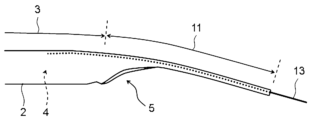
- Fig. 3 shows a side view of the proximal end of the tubular body of the extension guide catheter shown in Fig. 2, with the proximal end of the tubular body being bent
- FIG. 2 depicts a side view of the proximal end of the tubular body of the extension guide catheter shown in FIG. 1
- FIG. Figure 3 shows a bottom view of the proximal end of the tubular body of the extension guide catheter shown in Figure 2
- Figure 4 shows an enlarged view of the proximal end barrel of the extension guide
- FIG. 4 is a diagram showing a state in which an extension guide catheter according to an embodiment of the present invention is inserted into a guide catheter placed in a blood vessel and extended from an opening on the distal side of the guide catheter;
- FIG. 10B shows a side view of the proximal end of the tubular body of the extension guide catheter according to the comparative embodiment.
- Fig. 8 shows a side view of the proximal end of the tubular body of the extension guide catheter shown in Fig. 7 in a state where the proximal end of the tubular body is bent;
- the extension guide catheter of the present invention will be specifically described based on the following embodiments, but the present invention is not limited by the following embodiments, and is suitable within the scope that can conform to the gist of the above and later descriptions.
- hatching, member numbers, etc. may be omitted.
- the specification and other drawings shall be referred to.
- the dimensions of various members in the drawings may differ from the actual dimensions, since priority is given to helping to understand the features of the present invention.
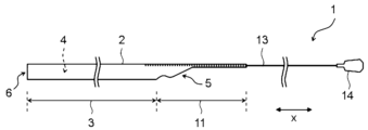
- FIG. 1 is an extension guide catheter according to an embodiment of the present invention, showing an overall view of the extension guide catheter
- FIG. 2 is a view of the proximal end of the tubular body of the extension guide catheter shown in FIG. 3 shows a view from below of the proximal end of the tubular body of the extension guide catheter shown in FIG. 2
- FIG. 4 shows the tubular body of the extension guide catheter shown in FIG. 5 depicts an enlarged view of the tubular body at the proximal end of the tubular body
- FIG. 5 is the proximal end of the tubular body of the extension guide catheter shown in FIG. is bent
- FIG. 6 shows that the extension guide catheter according to the embodiment of the present invention is inserted into the guide catheter placed in the blood vessel, and the opening on the distal side of the guide catheter is opened
- FIG. 10 shows a view showing a state extended from .
- the extension guide catheter is used in combination with the guide catheter. Specifically, it is inserted into the guide catheter and extended from the opening on the distal side of the guide catheter. By using the extension guide catheter, it is possible to stably deliver a treatment device such as an instrument for intravascular treatment to a farther periphery.
- a treatment device such as an instrument for intravascular treatment
- Devices for endovascular treatment include stents and balloons.
- an extension guide catheter 1 includes a tubular body 2 having a lumen 4 extending in the longitudinal direction x, and a tube fixed to the tubular body 2. and a linear member 13 extending proximally from the proximal side opening 5 of the tubular body 2 .
- the extension guide catheter 1 is used by inserting it into the guide catheter 21 previously placed in the body cavity during the operation. Specifically, the extension guide catheter 1 is inserted into the guide catheter 21 from the opening on the proximal side of the guide catheter 21, and the extension guide catheter 1 is extended distally from the opening 22 on the distal side of the guide catheter 21. It can be taken out and used.
- FIG. 6 shows a state in which the extension guide catheter 1 is placed inside the guide catheter 21 placed in the ascending aorta, and the extension guide catheter 1 extends from the opening 22 on the distal side of the guide catheter 21 .
- the extension guide catheter 1 advances or retracts the cylindrical body 2 within the guide catheter 21, or extends distally from the distal opening 22 of the guide catheter 21. can be pulled back into the guide catheter 21.
- a treatment device such as an instrument for intravascular treatment
- the treatment device can reach a more distal end within the body cavity.
- the inner diameter of the guide catheter 21 is larger than the outer diameter of the extension guide catheter 1 to accommodate the extension guide catheter 1 .
- the treatment device enters the guide catheter 21 from the proximal side opening of the guide catheter 21, passes through the guide catheter 21, and further enters the extension guide catheter 1 from the proximal side opening 5 of the extension guide catheter 1 to be the extension guide. By passing it through the inside of the catheter 1, it can be extended distally from the distal side opening 6 of the tubular body 2 of the extension guide catheter 1. As shown in FIG.
- the longitudinal axis direction x is defined as the extension direction of the extension guide catheter 1 , specifically the extension direction of the tubular body 2 and the linear member 13 .
- the extension guide catheter 1 has a proximal side and a distal side as one side and the other side with respect to the longitudinal axis direction x.
- the proximal side refers to the direction toward the hand side of the user, that is, the operator with respect to the extending direction of the extension guide catheter 1
- the distal side is the opposite direction to the proximal side, that is, Point in the direction of the side to be treated.
- the cylindrical body 2 has a radial direction as a direction orthogonal to the longitudinal axis direction x.
- the length of the extension guide catheter 1 in the longitudinal direction x is, for example, preferably 800 mm or more, more preferably 1000 mm or more, still more preferably 1200 mm or more, and preferably 2200 mm or less, more preferably 2000 mm or less, and even more preferably 1800 mm or less.
- the length of the cylindrical body 2 in the longitudinal direction x is, for example, preferably 100 mm or more, more preferably 200 mm or more, still more preferably 250 mm or more, preferably 600 mm or less, more preferably 500 mm or less, and even more preferably 450 mm or less. .
- the diameter of the lumen 4 of the cylindrical body 2 is preferably 1.0 mm or more. 2 mm or more is more preferable, 1.3 mm or more is still more preferable, 2.2 mm or less is preferable, 2.0 mm or less is more preferable, and 1.9 mm or less is even more preferable.
- the outer diameter of the cylindrical body 2 is preferably 1.2 mm or more, more preferably 1.3 mm or more, still more preferably 1.4 mm or more, and preferably 3.5 mm or less, more preferably 3.0 mm or less, and 2.5 mm.
- the thickness of the cylindrical body 2 is preferably 0.01 mm or more, more preferably 0.02 mm or more, still more preferably 0.05 mm or more, and preferably 0.4 mm or less, more preferably 0.3 mm or less, and 0.01 mm or more. 2 mm or less is more preferable.
- the shape of the lumen 4 of the tubular body 2 and the shape of the outer edge of the tubular body 2 are not particularly limited, and may be circular, elliptical, oval, or polygonal. , irregular shapes, and the like.
- the diameter of the lumen 4 of the tubular body 2 and the outer diameter of the tubular body 2 described above mean equivalent circle diameters. . That is, it means the diameter of a circle having the same length as the circumference of the lumen 4 of the tubular body 2 or the circumference of the outer edge of the tubular body 2 .
- the shape of the lumen 4 of the cylindrical body 2 and the shape of the outer edge of the cylindrical body 2 are preferably circular or elliptical. is preferred, 0.90 or more is more preferred, and 0.95 or more is even more preferred.
- the cylindrical body 2 can be made of resin, for example.
- resins include polyamide resins, polyester resins, polyurethane resins, polyolefin resins, fluorine-based resins, vinyl chloride-based resins, silicone resins, and natural rubber.
- Polyamide resins include nylon 12, nylon 12 elastomer, nylon 6, aromatic polyamides, and the like.
- Polyethylene terephthalate etc. are mentioned as a polyester resin.
- polyurethane resins include aliphatic polyurethanes containing aliphatic isocyanates as monomer units, aromatic polyurethanes containing aromatic isocyanates as monomer units, and the like.
- polyolefin resins include polyethylene and polypropylene.
- fluororesin examples include polytetrafluoroethylene, ethylenetetrafluoroethylene, fluorinated ethylenepropylene, and the like.
- vinyl chloride-based resins examples include polyvinyl chloride and polyvinylidene chloride.
- silicone resins include dimethylpolysiloxane, methylphenylpolysiloxane, methylvinylpolysiloxane, and fluoroalkylmethylpolysiloxane. Latex etc. are mentioned as natural rubber.
- the tubular body 2 may be composed of a single layer, or may be composed of multiple layers. Moreover, in the longitudinal direction x, part of the cylindrical body 2 may be composed of a single layer, and the other part may be composed of multiple layers.
- the tubular body 2 preferably has a reinforcing layer.
- the reinforcement layer can increase the rigidity of the cylindrical body 2 .
- the reinforcing layer may be provided on the inner surface of the tubular body 2 , may be provided on the outer surface, or may be provided between the inner and outer surfaces of the tubular body 2 .
- the reinforcing layer can be composed of metal wires, fibers, or the like.
- Materials constituting the metal wire include, for example, stainless steel, titanium, nickel-titanium alloys, cobalt-chromium alloys, and tungsten alloys. Among them, stainless steel is preferable.
- the metal wire may be a single wire or a twisted wire.
- fibers include polyarylate fibers, aramid fibers, ultra-high molecular weight polyethylene fibers, PBO (polyparaphenylenebenzoxazole) fibers, and carbon fibers.
- the fibers may be monofilaments or multifilaments.
- the shape of the reinforcing layer is not particularly limited, it is preferably spiral, mesh, or braided.
- the shape of the reinforcing layer is more preferably braided because the reinforcing layer can effectively increase the rigidity of the cylindrical body 2 .
- the cylindrical body 2 may contain a radiopaque material in order to facilitate confirmation of the position under X-ray fluoroscopy.
- Radiopaque materials include, for example, lead, barium, iodine, tungsten, gold, platinum, iridium, platinum-iridium alloys, stainless steel, titanium, cobalt-chromium alloys, palladium, tantalum, and the like.
- radiopaque markers are preferably provided at the proximal end and the distal end of the tubular body 2, so that the position of the tubular body 2 within the body cavity can be confirmed under X-ray fluoroscopy. can.
- the cylindrical body 2 may have its outer surface coated with a hydrophilic polymer. This facilitates insertion of the cylindrical body 2 into the guide catheter or blood vessel.
- hydrophilic polymers include hydrophilic polymers such as poly-2-hydroxyethyl methacrylate, polyacrylamide, polyvinylpyrrolidone, and maleic anhydride copolymers such as methyl vinyl ether maleic anhydride copolymers.
- the tubular body 2 preferably has an inner layer and an outer layer.
- the inner and outer layers can be composed of the resins described above.
- the inner layer is preferably composed of at least one selected from the group consisting of polyester resins, polyolefin resins, fluororesins, silicone resins, and natural rubbers.
- the inner layer is preferably composed of a fluororesin.
- the outer layer is preferably composed of at least one resin selected from the group consisting of polyamide resins, polyurethane resins, and polyolefin resins, and is composed of at least one resin selected from the group consisting of polyamide resins and polyurethane resins. More preferably, it is made of a polyurethane resin.
- the tubular body 2 preferably has a reinforcing layer in addition to the inner layer and the outer layer.
- the reinforcing layer may be provided on the outer layer, on the inner layer, or between the inner layer and the outer layer. It is preferably provided between outer layers.
- the linear member 13 is an elongated wire and fixed to the proximal end of the cylindrical body 2 .
- the tubular body 2 can be advanced or retracted, thereby causing the tubular body 2 to protrude from the opening on the distal side of the guide catheter or to move the tubular body 2 forward. It can be pulled back into the guide catheter.
- the linear member 13 is preferably made of metal.
- the metal forming the linear member 13 include stainless steel, titanium, nickel-titanium alloys, cobalt-chromium alloys, tungsten alloys, etc. Among them, stainless steel is more preferable.
- the cross-sectional shape of the linear member 13 in the direction perpendicular to the longitudinal axis direction x is not particularly limited. Especially, it is preferable that the cross-sectional shape of the linear member 13 is a square.
- the extension guide catheter 1 is preferably provided with a grasping member 14 at the proximal end of the linear member 13 . By gripping the gripping member 14 with fingers, the operator can easily push in and pull out the extension guide catheter 1 .
- materials for the grip member 14 include resins, and examples of resins include polyolefin resins such as polyethylene and polypropylene.
- the linear member 13 may be fixed to the inner surface of the tubular body 2, may be fixed to the outer surface of the tubular body 2, or may be fixed between the inner and outer surfaces of the tubular body 2. good too.
- the linear member 13 may be fixed to the inner layer of the cylindrical body 2, the outer layer, or between the inner layer and the outer layer.
- the linear member 13 is fixed to one side of the cylindrical body 2 in the radial direction, and the cylindrical body 2 is defined such that the side to which the linear member 13 is fixed is the upper side and the opposite side is the lower side with respect to the radial direction. be done.
- the cylindrical body 2 has an upper side to which the linear member 13 is fixed and a lower side opposite to the upper side with respect to the radial direction.
- the direction extending from the upper side to the lower side is referred to as the vertical direction, and the direction orthogonal thereto is referred to as the width direction.
- the cylindrical body 2 has a proximal opening 5 and a distal opening 6.
- the proximal opening 5 of the tubular body 2 means the opening on the proximal side of the lumen 4 of the tubular body 2
- the distal opening 6 of the tubular body 2 means the inside of the tubular body 2 . It means the distal opening of cavity 4 .
- the proximal side opening 5 of the cylindrical body 2 has a portion inclined with respect to the longitudinal axis direction x.
- the cylindrical body 2 has a cylindrical portion 3 formed in a cylindrical shape and a non-cylindrical proximal extension portion 11 extending proximally from the cylindrical portion 3, and the outer edge of the proximal side opening 5 is It is formed on the proximal extension portion 11 .
- a bore 4 of the tubular body 2 is formed in the tubular portion 3 .
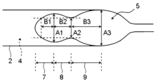
- the proximal opening 5 has a first section 7, a second section 8 proximal to the first section 7, and a third section proximal to the second section 8 with respect to the longitudinal axis direction x.
- a proximal extension portion 11 formed with the outer edge of the proximal side opening 5, specifically, a longitudinal portion in which the first section 7 to the third section 9 of the proximal extension portion 11 are formed
- a portion within the range in the axial direction x and a portion adjacent to the distal side thereof are referred to as a proximal end portion of the tubular body 2 .
- the portion of the proximal extension portion 11 in which the first section 7 to the third section 9 are formed and the portion within 20 mm distally from the proximal end of the tubular portion 3 adjacent thereto are formed into a tubular shape. It can be the proximal end of body 2 .
- the portion of the longitudinal axis direction x where the first section 7 is formed is referred to as the first section 7 of the proximal extension portion 11 .
- the section with respect to the longitudinal axis direction x is defined based on each section.
- the width of the proximal opening 5 gradually increases from the distal side to the proximal side in the first section 7 and increases in the second section 8 .
- the width gradually decreases from the distal side to the proximal side, and the width of the third section 9 gradually increases from the distal side to the proximal side.
- the proximal opening 5 of the tubular body 2 is formed in this way, so that the proximal end portion of the tubular body 2 is bent in a body cavity such as a blood vessel.
- the tubular body 2 is deformed so that the size of the proximal side opening 5 expands when positioned at a bent portion of the guide catheter, and a treatment device such as an endovascular treatment instrument is placed near the tubular body 2. It becomes easy to insert into the lumen 4 of the cylindrical body 2 from the position side opening 5 .
- the extension guide catheter 1 is used by inserting it into the guide catheter and the body cavity.
- the proximal end of the tubular body 2 may be located in a body cavity or a bent portion of the guide catheter.
- the proximal end of the tubular body 2 is bent with the lower side of the tubular body 2 inside along the bent portion of the body cavity or the guide catheter. 4 may be crushed, or the cross-sectional shape of the lumen 4 may be distorted to narrow the cross-sectional area.
- the extension guide catheter 1 has the first section 7, the second section 8, and the third section 9 formed in the proximal side opening 5 as described above, the proximal end of the cylindrical body 2 extends into the body cavity.
- the tubular body 2 opens the proximal side opening 5 when viewed from below. It deforms and the size of the proximal side opening 5 expands.
- the lumen 4 of the cylindrical body 2 may be crushed or the cross-sectional shape of the lumen 4 may be distorted to increase the cross-sectional area. Narrowing can be suppressed. Therefore, it becomes easier to insert the treatment device into the lumen 4 of the tubular body 2 from the proximal opening 5 of the tubular body 2 .
- the distal end of the proximal opening 5 is distorted and tends to bend inward in a distorted shape.
- the lower portion of the lumen 4 of the tubular body 2 is distorted, the cross-sectional area of the lumen 4 is narrowed, and the insertion of the treatment device into the proximal opening 5 of the tubular body 2 is hindered.
- the proximal opening 5 is provided with the first section 7, the second section 8, and the third section 9, when the force in the bending direction is applied to the third section 9 of the proximal extension portion 11, , the force is transmitted to the second section 8, which can be deformed so that the lower portion of the proximal opening 5 opens at the second section 8, as shown in FIG.
- the proximal extension portion 11 can be easily bent from the first section 7 to the second section 8, and at that time, along with the bending, the proximal extension portion 11 can be bent from the second section 8 to the third section 9.
- the lower part of the side opening 5 can be deformed to open.
- proximal extension portion 11 is bent from the first section 7 to the second section 8
- distortion is less likely to occur in this section, and the proximal end portion of the tubular body 2 is bent with a larger curvature.
- the proximal opening 5 is widened from the first section 7 to the second section 8, the lower portion of the proximal opening 5 opens from the second section 8 to the third section 9. By doing so, a large opening is formed on the lower side of the tubular body 2 .
- the treatment device when the treatment device is inserted from the proximal opening 5 of the tubular body 2 , the treatment device is less likely to be caught on the outer edge of the proximal opening 5 of the tubular body 2 , and the treatment device is inserted proximally of the tubular body 2 . Insertion into the side opening 5 is facilitated.
- the width of the proximal side opening 5 is determined based on the projected shape of the outer edge of the proximal side opening 5 when the cylindrical body 2 is viewed from below, and the width It is obtained by measuring the length between both ends of the outer edge of the proximal opening 5 with respect to the direction.
- the outer edge of the proximal opening 5, when viewed from the bottom side of the tubular body 2, may be formed in a straight line shape, may be formed in a curved shape, or may be formed in a combination of these shapes. may be
- the outer edge of the proximal side opening 5 is preferably formed line-symmetrically in the width direction.
- the width of the proximal opening 5 is the length in the width direction between both ends of the outer edge of the proximal opening 5 at the same position in the vertical direction in the vertical cross section of the proximal opening 5 in the longitudinal axis direction x. It can be obtained by measuring. If the proximal side opening 5 is formed in this way, the proximal end portion of the tubular body 2 is greatly distorted when the proximal end portion of the tubular body 2 is positioned in the body cavity or the bent portion of the guide catheter.
- forming symmetrically in the width direction means forming symmetrically with respect to a plane defined by the longitudinal axis direction x and the vertical direction.
- first section 7 of the proximal opening 5 is preferably the distal end of the proximal opening 5 . Therefore, first section 7 is preferably formed including the distal end of proximal opening 5 .
- the proximal opening 5 may also be present on the proximal side of the proximal end of the third section 9, for example, on the proximal side of the third section 9, from the distal side to the proximal side. You may have the 4th section 10 formed so that width may taper toward a side.
- the outer edge of the proximal opening 5 is preferably formed in the lower half portion of the cylindrical body 2 from the distal end of the first section 7 to the proximal end of the second section 8 . This prevents the proximal extension portion 11 from excessively bending from the first section 7 to the second section 8 when the proximal end portion of the cylindrical body 2 is positioned in a body cavity or a bent portion of the guide catheter. can be suppressed. Therefore, when inserting the treatment device through the proximal opening 5 , it is possible to prevent the treatment device from being caught on the outer edge of the proximal opening 5 .
- the outer edge of the proximal opening 5 is preferably formed in the lower half portion of the tubular body 2 also in the third section 9 . Therefore, the outer edge of the proximal opening 5 is preferably formed in the lower half portion of the cylindrical body 2 in the first section 7 to the third section 9 . In this case, the proximal end of the third section 9 preferably coincides with the proximal end of the lower half portion of the tubular body 2 . Moreover, in the fourth section 10 on the proximal side of the third section 9 , the outer edge of the proximal opening 5 is preferably formed in the upper half portion of the tubular body 2 .
- the length in the longitudinal direction x from the distal end of the first section 7 to the proximal end of the second section 8 is 0.3 times or more the width of the proximal side opening 5 at the proximal end of the third section 9 is preferred, 0.6 times or more is more preferred, and 1 time or more is even more preferred.
- the proximal end portion of the cylindrical body 2 is bent, the lower portion of the proximal side opening 5 can be smoothly deformed so as to widen.
- the treatment device moves toward the outer edge of the proximal opening 5 of the tubular body 2, particularly the second section 8 to the third section 9 of the proximal extending portion 11.
- the length of the longitudinal axis direction x from the distal end of the first section 7 to the proximal end of the second section 8 is 15 times or less the width of the proximal opening 5 at the proximal end of the third section 9. is preferred, 12 times or less is more preferred, and 10 times or less is even more preferred.
- the lengths of the first section 7 and the second section 8 in the longitudinal axis direction x of the proximal extension portion 11 are not excessively long, and the proximal end portion of the tubular body 2 is positioned in a body cavity or a guide catheter.
- the force in the bending direction is likely to be applied to the third section 9 of the proximal extension portion 11 . Therefore, the force applied to the third section 9 of the proximal extension portion 11 is transmitted to the second section 8 , and the second section 8 easily deforms so that the lower portion of the proximal side opening 5 opens.
- the length of the first section 7 in the longitudinal direction x and/or the length of the second section 8 in the longitudinal direction x is preferably equal to or less than the length of the third section 9 in the longitudinal direction x. If the proximal side opening 5 is formed in this way, when the proximal extending portion 11 is bent from the first section 7 to the second section 8, distortion is less likely to occur in that portion. Therefore, when inserting the treatment device from the proximal opening 5 of the tubular body 2 , the treatment device is less likely to get caught on the outer edge of the proximal opening 5 of the tubular body 2 .
- both the length in the longitudinal axis direction x of the first section 7 and the length in the longitudinal axis direction x of the second section 8 may be less than or equal to the length in the longitudinal axis direction x of the third section 9 .
- the width of the proximal opening 5 at the distal end of the third section 9 is preferably 0.3 times or more the width of the proximal opening 5 at the proximal end of the third section 9, such as 0.4 times. 0.5 times or more is more preferable. If the proximal side opening 5 is formed in this way, when the treatment device is inserted through the proximal side opening 5 of the tubular body 2, the treatment device is inserted through the second section 8 of the proximal extension portion 11. It becomes difficult to get caught on the protruding part over the third section 9.
- the width of the proximal opening 5 at the distal end of the third section 9 is preferably 0.9 times or less than the width of the proximal opening 5 at the proximal end of the third section 9.
- the length of the third section 9 in the longitudinal direction x is ensured. Therefore, when the proximal end portion of the cylindrical body 2 is positioned in the body cavity or the bent portion of the guide catheter, the force applied to the third section 9 of the proximal extension portion 11 is transmitted to the second section 8, The two sections 8 facilitate deformation so that the lower portion of the proximal opening 5 opens.
- the width of the proximal opening 5 at the distal end of the second section 8 is preferably 0.4 to 1.0 times the width of the proximal opening 5 at the proximal end of the third section 9. , is more preferably 0.5 times or more, and more preferably 0.6 times or more.
- the first section 7, the second section 8 and the third section 9 are preferably formed so as to satisfy one or both of the following formulas (1) and (2).
- A1 to A3 and B1 to B3 mean the length of each part shown in FIG. 4, specifically, A1 represents the width of the proximal opening 5 at the proximal end of the first section 7. , A2 represents the width of the proximal opening 5 at the proximal end of the second section 8, A3 represents the width of the proximal opening 5 at the proximal end of the third section 9, and B1 represents the width of the first represents the length in the longitudinal direction x from the proximal end of the section 7 to the point in the first section 7 where the width of the proximal opening 5 is A2, where B2 is the longitudinal direction x of the second section 8 and B3 represents the length of the third section 9 in the longitudinal direction x.
- the proximal extension portion 11 can be smoothly bent from the first section 7 to the second section 8, and the proximal end portion of the cylindrical body 2 can be enlarged. Easier to bend.
- the first section 7, the second section 8 and the third section 9 are preferably formed so as to satisfy at least one of the above formulas (1) and (2), but more preferably the above formula (1) and Equation (2).
- the outer edge of the proximal side opening 5 extends so that the angle formed by the longitudinal axis direction x is 60° or less in the second section 8 and the third section 9. is preferably 50° or less, and even more preferably 45° or less.
- the angle formed by the outer edge of the proximal side opening 5 with the longitudinal axis direction x in the range of the proximal side 1/2 of the first section 7, preferably in the range of the proximal side 2/3 is preferably 60° or less, more preferably 50° or less, and even more preferably 45° or less.
- the treatment device is less likely to get caught on the outer edge of the proximal opening 5 when the treatment device is inserted through the proximal opening 5 of the tubular body 2 . Become.
- the outer edge of the proximal opening 5 has a portion extending parallel to the longitudinal direction x between the first section 7 and the second section 8 and/or between the second section 8 and the third section 9.
- the proximal opening 5 does not vary in width from distal to proximal between the first section 7 and the second section 8 and/or between the second section 8 and the third section 9. It may have a portion extending to The length of the portion where the proximal side opening 5 extends in the longitudinal direction x with a constant width is the length of the length in the longitudinal direction x from the distal end of the first section 7 to the proximal end of the third section 9 . It is preferably 1/3 or less of the height, more preferably 1/4 or less.
- the outer edge of the proximal opening 5 may also have a portion extending parallel to the longitudinal axis direction x between the third section 9 and the fourth section 10, in which case the proximal opening 5
- the length of the portion extending in the longitudinal direction x with a constant width is 1/3 or less of the length in the longitudinal direction x from the distal end of the first section 7 to the proximal end of the fourth section 10 It is preferably 1/4 or less, more preferably 1/4 or less.
- the linear member 13 is preferably fixed to the tubular body 2 at the proximal extension portion 11 .
- the linear member 13 preferably extends further distally than the distal end of the proximal opening 5 . Therefore, it is preferable that the distal end of the linear member 13 be located on the distal side of the distal end of the proximal opening 5 .
- the linear member 13 is also preferably fixed to the tubular body 2 on the distal side of the distal end of the proximal opening 5 .
- the linear member 13 By fixing the linear member 13 to the cylindrical body 2 in this way, it becomes easy to move the cylindrical body 2 forward by pushing the linear member 13 .
- the lumen 4 of the cylindrical body 2 is less likely to be crushed at the body cavity or the bent portion of the guide catheter.
- the proximal extending portion 11 preferably has a belt-like portion 12 that is positioned proximally relative to the third section 9 or the fourth section 10 and extends parallel to the longitudinal axis direction x.
- the band-shaped portion 12 is formed on the upper portion of the cylindrical body 2 and the linear member 13 is arranged along the band-shaped portion 12 and fixed to the band-shaped portion 12 .
- the length in the longitudinal direction x of the belt-like portion 12 is, for example, preferably 50 mm or longer, more preferably 80 mm or longer, still more preferably 100 mm or longer, preferably 200 mm or shorter, more preferably 180 mm or shorter, and even more preferably 150 mm or shorter.
- the linear member 13 can be stably fixed to the cylindrical body 2 .
- the tubular portion 3 of the tubular body 2 has a resin layer and a reinforcing layer in which metal wires or fibers are arranged in a spiral, mesh, or braid, and the proximal end of the reinforcing layer faces the proximal side. It is preferably within 15 mm distally from the distal end of the opening 5, more preferably within 10 mm, and even more preferably within 8 mm. By providing the reinforcing layer in this manner, the lumen 4 of the tubular body 2 is less likely to be crushed, making it easier to insert a treatment device into the lumen 4 of the tubular body 2 .
- the resin layer of the tubular portion 3 preferably includes the inner layer and the outer layer described above.
- the proximal extension portion 11 of the tubular body 2 preferably has the inner layer and the outer layer described above. In addition, it is preferable that the proximal extension portion 11 is not provided with a reinforcing layer. In addition, the proximal extending portion 11 of the tubular body 2 tends to bend more preferentially than the tubular portion 3 , so that the tubular portion 3 is prevented from being largely distorted or kinked.
- Extension guide catheter 2 Tubular body 3: Tubular portion 4: Lumen 5: Proximal side opening 6: Distal side opening 7: First section 8: Second section 9: Third section 10: Fourth Section 11: Proximal extending portion 12: Band-shaped portion 13: Linear member 14: Grasping member 21: Guide catheter
Landscapes
- Health & Medical Sciences (AREA)
- Life Sciences & Earth Sciences (AREA)
- Biophysics (AREA)
- Pulmonology (AREA)
- Engineering & Computer Science (AREA)
- Anesthesiology (AREA)
- Biomedical Technology (AREA)
- Heart & Thoracic Surgery (AREA)
- Hematology (AREA)
- Animal Behavior & Ethology (AREA)
- General Health & Medical Sciences (AREA)
- Public Health (AREA)
- Veterinary Medicine (AREA)
- Media Introduction/Drainage Providing Device (AREA)
Abstract
L'invention concerne un cathéter de guidage d'extension pour un cathéter de guidage, le cathéter de guidage d'extension ayant un corps tubulaire (2) ayant une lumière (4) s'étendant dans la direction longitudinale du cathéter de guidage, et un élément linéaire (13) s'étendant sur le côté proximal du corps tubulaire (2) : une ouverture côté proximal (5) du corps tubulaire (2) présentant, à partir de son côté distal, une première section (7), une deuxième section (8), et une troisième section (9) ; et l'ouverture côté proximal (5) est formée de telle sorte que, lorsque le corps tubulaire (2) est vu de dessous, la largeur du corps tubulaire augmente progressivement depuis le côté distal vers le côté proximal dans la première section (7), la largeur diminue progressivement depuis le côté distal vers le côté proximal dans la deuxième section (8), et la largeur augmente progressivement depuis le côté distal vers le côté proximal dans la troisième section (9).
Priority Applications (1)
| Application Number | Priority Date | Filing Date | Title |
|---|---|---|---|
| JP2023555012A JPWO2023062984A1 (fr) | 2021-10-14 | 2022-09-08 |
Applications Claiming Priority (2)
| Application Number | Priority Date | Filing Date | Title |
|---|---|---|---|
| JP2021-169116 | 2021-10-14 | ||
| JP2021169116 | 2021-10-14 |
Publications (1)
| Publication Number | Publication Date |
|---|---|
| WO2023062984A1 true WO2023062984A1 (fr) | 2023-04-20 |
Family
ID=85987433
Family Applications (1)
| Application Number | Title | Priority Date | Filing Date |
|---|---|---|---|
| PCT/JP2022/033695 WO2023062984A1 (fr) | 2021-10-14 | 2022-09-08 | Cathéter de guidage d'extension |
Country Status (2)
| Country | Link |
|---|---|
| JP (1) | JPWO2023062984A1 (fr) |
| WO (1) | WO2023062984A1 (fr) |
Citations (3)
| Publication number | Priority date | Publication date | Assignee | Title |
|---|---|---|---|---|
| JP2017533012A (ja) * | 2014-11-04 | 2017-11-09 | オーバスネイチ メディカル、インコーポレイテッド | 累加柔軟性カテーテル支持フレーム |
| JP2017534367A (ja) * | 2014-10-07 | 2017-11-24 | キューエックスメディカル リミテッド ライアビリティ カンパニー | 区分されたカテーテル構造および改善されたカテーテル先端および関連したシステム、方法、およびデバイス |
| JP2018508281A (ja) * | 2015-05-26 | 2018-03-29 | テレフレックス イノベーションズ エス.アー.エール.エル. | ガイドワイヤ固定 |
-
2022
- 2022-09-08 WO PCT/JP2022/033695 patent/WO2023062984A1/fr active Application Filing
- 2022-09-08 JP JP2023555012A patent/JPWO2023062984A1/ja active Pending
Patent Citations (3)
| Publication number | Priority date | Publication date | Assignee | Title |
|---|---|---|---|---|
| JP2017534367A (ja) * | 2014-10-07 | 2017-11-24 | キューエックスメディカル リミテッド ライアビリティ カンパニー | 区分されたカテーテル構造および改善されたカテーテル先端および関連したシステム、方法、およびデバイス |
| JP2017533012A (ja) * | 2014-11-04 | 2017-11-09 | オーバスネイチ メディカル、インコーポレイテッド | 累加柔軟性カテーテル支持フレーム |
| JP2018508281A (ja) * | 2015-05-26 | 2018-03-29 | テレフレックス イノベーションズ エス.アー.エール.エル. | ガイドワイヤ固定 |
Also Published As
| Publication number | Publication date |
|---|---|
| JPWO2023062984A1 (fr) | 2023-04-20 |
Similar Documents
| Publication | Publication Date | Title |
|---|---|---|
| US11712544B2 (en) | Guide extension catheter | |
| EP1712247B1 (fr) | Cathéter | |
| JP5639580B2 (ja) | 医療用ガイドワイヤ | |
| US20220126067A1 (en) | Extension catheter and method for producing same | |
| KR102315805B1 (ko) | 대형 루멘 안내 카테터 | |
| JP4754843B2 (ja) | カテーテル | |
| EP4039315B1 (fr) | Cathéter d'extension de guidage | |
| JP4790349B2 (ja) | カテーテル | |
| JP2006513774A (ja) | 多重編組型外装チューブ | |
| EP1807144A1 (fr) | Gaine a large diametre | |
| JP2006218070A (ja) | カテーテル | |
| WO2023062984A1 (fr) | Cathéter de guidage d'extension | |
| WO2023062982A1 (fr) | Cathéter de guidage d'extension | |
| WO2023062983A1 (fr) | Cathéter de guidage d'extension | |
| WO2023062985A1 (fr) | Cathéter de guidage d'extension | |
| US20220000647A1 (en) | Stent delivery apparatus | |
| JP2023059156A (ja) | 延長ガイドカテーテル | |
| JP7444879B2 (ja) | カテーテル、及びカテーテルの製造方法 | |
| JP7378460B2 (ja) | 医療用管状体搬送装置およびその製造方法 | |
| JP7524080B2 (ja) | 延長カテーテル、及びその製造方法 | |
| JP7498709B2 (ja) | カテーテル | |
| JP2024139235A (ja) | 延長ガイドカテーテル | |
| WO2023189378A1 (fr) | Cathéter | |
| WO2022154118A1 (fr) | Cathéter et ensemble cathéter | |
| JP2024012725A (ja) | カテーテル |
Legal Events
| Date | Code | Title | Description |
|---|---|---|---|
| 121 | Ep: the epo has been informed by wipo that ep was designated in this application |
Ref document number: 22880680 Country of ref document: EP Kind code of ref document: A1 |
|
| WWE | Wipo information: entry into national phase |
Ref document number: 2023555012 Country of ref document: JP |
|
| NENP | Non-entry into the national phase |
Ref country code: DE |
|
| 122 | Ep: pct application non-entry in european phase |
Ref document number: 22880680 Country of ref document: EP Kind code of ref document: A1 |