WO2023062984A1 - Extension guide catheter - Google Patents
Extension guide catheter Download PDFInfo
- Publication number
- WO2023062984A1 WO2023062984A1 PCT/JP2022/033695 JP2022033695W WO2023062984A1 WO 2023062984 A1 WO2023062984 A1 WO 2023062984A1 JP 2022033695 W JP2022033695 W JP 2022033695W WO 2023062984 A1 WO2023062984 A1 WO 2023062984A1
- Authority
- WO
- WIPO (PCT)
- Prior art keywords
- section
- proximal
- guide catheter
- opening
- tubular body
- Prior art date
Links
- 230000007423 decrease Effects 0.000 claims abstract description 4
- 239000010410 layer Substances 0.000 description 38
- 238000011282 treatment Methods 0.000 description 31
- 230000003014 reinforcing effect Effects 0.000 description 12
- 229920005989 resin Polymers 0.000 description 12
- 239000011347 resin Substances 0.000 description 12
- -1 Polyethylene terephthalate Polymers 0.000 description 9
- 238000005452 bending Methods 0.000 description 8
- 238000012276 Endovascular treatment Methods 0.000 description 7
- 239000000835 fiber Substances 0.000 description 7
- 229910052751 metal Inorganic materials 0.000 description 6
- 239000002184 metal Substances 0.000 description 6
- 210000004204 blood vessel Anatomy 0.000 description 5
- 238000003780 insertion Methods 0.000 description 5
- 230000037431 insertion Effects 0.000 description 5
- 229920005672 polyolefin resin Polymers 0.000 description 5
- 229920005749 polyurethane resin Polymers 0.000 description 5
- 239000010935 stainless steel Substances 0.000 description 5
- 229910001220 stainless steel Inorganic materials 0.000 description 5
- 239000000463 material Substances 0.000 description 4
- 229920006122 polyamide resin Polymers 0.000 description 4
- 244000043261 Hevea brasiliensis Species 0.000 description 3
- RTAQQCXQSZGOHL-UHFFFAOYSA-N Titanium Chemical compound [Ti] RTAQQCXQSZGOHL-UHFFFAOYSA-N 0.000 description 3
- 239000000788 chromium alloy Substances 0.000 description 3
- 210000004351 coronary vessel Anatomy 0.000 description 3
- 229920001477 hydrophilic polymer Polymers 0.000 description 3
- 229920003052 natural elastomer Polymers 0.000 description 3
- 229920001194 natural rubber Polymers 0.000 description 3
- 229920001225 polyester resin Polymers 0.000 description 3
- 239000004645 polyester resin Substances 0.000 description 3
- 229920002050 silicone resin Polymers 0.000 description 3
- 239000010936 titanium Substances 0.000 description 3
- 229910052719 titanium Inorganic materials 0.000 description 3
- JHWNWJKBPDFINM-UHFFFAOYSA-N Laurolactam Chemical compound O=C1CCCCCCCCCCCN1 JHWNWJKBPDFINM-UHFFFAOYSA-N 0.000 description 2
- 229920000299 Nylon 12 Polymers 0.000 description 2
- KDLHZDBZIXYQEI-UHFFFAOYSA-N Palladium Chemical compound [Pd] KDLHZDBZIXYQEI-UHFFFAOYSA-N 0.000 description 2
- 239000004698 Polyethylene Substances 0.000 description 2
- 239000004743 Polypropylene Substances 0.000 description 2
- BZHJMEDXRYGGRV-UHFFFAOYSA-N Vinyl chloride Chemical compound ClC=C BZHJMEDXRYGGRV-UHFFFAOYSA-N 0.000 description 2
- 229910001080 W alloy Inorganic materials 0.000 description 2
- HZEWFHLRYVTOIW-UHFFFAOYSA-N [Ti].[Ni] Chemical compound [Ti].[Ni] HZEWFHLRYVTOIW-UHFFFAOYSA-N 0.000 description 2
- 229910045601 alloy Inorganic materials 0.000 description 2
- 239000000956 alloy Substances 0.000 description 2
- 239000004760 aramid Substances 0.000 description 2
- 229920001577 copolymer Polymers 0.000 description 2
- 238000002594 fluoroscopy Methods 0.000 description 2
- 239000012948 isocyanate Substances 0.000 description 2
- 239000000178 monomer Substances 0.000 description 2
- 229910001000 nickel titanium Inorganic materials 0.000 description 2
- BASFCYQUMIYNBI-UHFFFAOYSA-N platinum Chemical compound [Pt] BASFCYQUMIYNBI-UHFFFAOYSA-N 0.000 description 2
- 229920000573 polyethylene Polymers 0.000 description 2
- 229920001155 polypropylene Polymers 0.000 description 2
- 229920002635 polyurethane Polymers 0.000 description 2
- 239000004814 polyurethane Substances 0.000 description 2
- 239000002356 single layer Substances 0.000 description 2
- 206010002383 Angina Pectoris Diseases 0.000 description 1
- 229920000049 Carbon (fiber) Polymers 0.000 description 1
- 201000000057 Coronary Stenosis Diseases 0.000 description 1
- 206010011089 Coronary artery stenosis Diseases 0.000 description 1
- 239000004812 Fluorinated ethylene propylene Substances 0.000 description 1
- YCKRFDGAMUMZLT-UHFFFAOYSA-N Fluorine atom Chemical compound [F] YCKRFDGAMUMZLT-UHFFFAOYSA-N 0.000 description 1
- WOBHKFSMXKNTIM-UHFFFAOYSA-N Hydroxyethyl methacrylate Chemical compound CC(=C)C(=O)OCCO WOBHKFSMXKNTIM-UHFFFAOYSA-N 0.000 description 1
- 229920002292 Nylon 6 Polymers 0.000 description 1
- 229920001328 Polyvinylidene chloride Polymers 0.000 description 1
- 239000004699 Ultra-high molecular weight polyethylene Substances 0.000 description 1
- 125000001931 aliphatic group Chemical group 0.000 description 1
- 210000000709 aorta Anatomy 0.000 description 1
- 229920006231 aramid fiber Polymers 0.000 description 1
- 229920003235 aromatic polyamide Polymers 0.000 description 1
- 125000003118 aryl group Chemical group 0.000 description 1
- 229910052788 barium Inorganic materials 0.000 description 1
- DSAJWYNOEDNPEQ-UHFFFAOYSA-N barium atom Chemical compound [Ba] DSAJWYNOEDNPEQ-UHFFFAOYSA-N 0.000 description 1
- 230000017531 blood circulation Effects 0.000 description 1
- 239000004917 carbon fiber Substances 0.000 description 1
- 230000000052 comparative effect Effects 0.000 description 1
- 238000012790 confirmation Methods 0.000 description 1
- 238000007887 coronary angioplasty Methods 0.000 description 1
- 238000010586 diagram Methods 0.000 description 1
- 235000013870 dimethyl polysiloxane Nutrition 0.000 description 1
- 239000004205 dimethyl polysiloxane Substances 0.000 description 1
- 229920001971 elastomer Polymers 0.000 description 1
- 239000000806 elastomer Substances 0.000 description 1
- 229910052731 fluorine Inorganic materials 0.000 description 1
- 239000011737 fluorine Substances 0.000 description 1
- PCHJSUWPFVWCPO-UHFFFAOYSA-N gold Chemical compound [Au] PCHJSUWPFVWCPO-UHFFFAOYSA-N 0.000 description 1
- 229910052737 gold Inorganic materials 0.000 description 1
- 239000010931 gold Substances 0.000 description 1
- 230000012447 hatching Effects 0.000 description 1
- PNDPGZBMCMUPRI-UHFFFAOYSA-N iodine Chemical compound II PNDPGZBMCMUPRI-UHFFFAOYSA-N 0.000 description 1
- 229910052741 iridium Inorganic materials 0.000 description 1
- GKOZUEZYRPOHIO-UHFFFAOYSA-N iridium atom Chemical compound [Ir] GKOZUEZYRPOHIO-UHFFFAOYSA-N 0.000 description 1
- 230000001788 irregular Effects 0.000 description 1
- 239000004816 latex Substances 0.000 description 1
- 229920000126 latex Polymers 0.000 description 1
- 208000010125 myocardial infarction Diseases 0.000 description 1
- 208000031225 myocardial ischemia Diseases 0.000 description 1
- 229910052763 palladium Inorganic materials 0.000 description 1
- 229920009441 perflouroethylene propylene Polymers 0.000 description 1
- 230000002093 peripheral effect Effects 0.000 description 1
- 229910052697 platinum Inorganic materials 0.000 description 1
- HWLDNSXPUQTBOD-UHFFFAOYSA-N platinum-iridium alloy Chemical class [Ir].[Pt] HWLDNSXPUQTBOD-UHFFFAOYSA-N 0.000 description 1
- 229920000435 poly(dimethylsiloxane) Polymers 0.000 description 1
- 229920002401 polyacrylamide Polymers 0.000 description 1
- 229920001230 polyarylate Polymers 0.000 description 1
- 229920000139 polyethylene terephthalate Polymers 0.000 description 1
- 239000005020 polyethylene terephthalate Substances 0.000 description 1
- 229920000915 polyvinyl chloride Polymers 0.000 description 1
- 239000004800 polyvinyl chloride Substances 0.000 description 1
- 239000005033 polyvinylidene chloride Substances 0.000 description 1
- 229920000036 polyvinylpyrrolidone Polymers 0.000 description 1
- 235000013855 polyvinylpyrrolidone Nutrition 0.000 description 1
- 239000001267 polyvinylpyrrolidone Substances 0.000 description 1
- 230000001144 postural effect Effects 0.000 description 1
- 230000002787 reinforcement Effects 0.000 description 1
- 239000000126 substance Substances 0.000 description 1
- 229910052715 tantalum Inorganic materials 0.000 description 1
- GUVRBAGPIYLISA-UHFFFAOYSA-N tantalum atom Chemical compound [Ta] GUVRBAGPIYLISA-UHFFFAOYSA-N 0.000 description 1
- WFKWXMTUELFFGS-UHFFFAOYSA-N tungsten Chemical compound [W] WFKWXMTUELFFGS-UHFFFAOYSA-N 0.000 description 1
- 239000010937 tungsten Substances 0.000 description 1
- 229910052721 tungsten Inorganic materials 0.000 description 1
- 229920000785 ultra high molecular weight polyethylene Polymers 0.000 description 1
Images


Classifications
-
- A—HUMAN NECESSITIES
- A61—MEDICAL OR VETERINARY SCIENCE; HYGIENE
- A61M—DEVICES FOR INTRODUCING MEDIA INTO, OR ONTO, THE BODY; DEVICES FOR TRANSDUCING BODY MEDIA OR FOR TAKING MEDIA FROM THE BODY; DEVICES FOR PRODUCING OR ENDING SLEEP OR STUPOR
- A61M25/00—Catheters; Hollow probes
- A61M25/01—Introducing, guiding, advancing, emplacing or holding catheters
- A61M25/06—Body-piercing guide needles or the like
- A61M25/0662—Guide tubes
-
- A—HUMAN NECESSITIES
- A61—MEDICAL OR VETERINARY SCIENCE; HYGIENE
- A61M—DEVICES FOR INTRODUCING MEDIA INTO, OR ONTO, THE BODY; DEVICES FOR TRANSDUCING BODY MEDIA OR FOR TAKING MEDIA FROM THE BODY; DEVICES FOR PRODUCING OR ENDING SLEEP OR STUPOR
- A61M25/00—Catheters; Hollow probes
- A61M25/01—Introducing, guiding, advancing, emplacing or holding catheters
-
- A—HUMAN NECESSITIES
- A61—MEDICAL OR VETERINARY SCIENCE; HYGIENE
- A61M—DEVICES FOR INTRODUCING MEDIA INTO, OR ONTO, THE BODY; DEVICES FOR TRANSDUCING BODY MEDIA OR FOR TAKING MEDIA FROM THE BODY; DEVICES FOR PRODUCING OR ENDING SLEEP OR STUPOR
- A61M25/00—Catheters; Hollow probes
- A61M2025/0004—Catheters; Hollow probes having two or more concentrically arranged tubes for forming a concentric catheter system
Landscapes
- Health & Medical Sciences (AREA)
- Life Sciences & Earth Sciences (AREA)
- Biophysics (AREA)
- Pulmonology (AREA)
- Engineering & Computer Science (AREA)
- Anesthesiology (AREA)
- Biomedical Technology (AREA)
- Heart & Thoracic Surgery (AREA)
- Hematology (AREA)
- Animal Behavior & Ethology (AREA)
- General Health & Medical Sciences (AREA)
- Public Health (AREA)
- Veterinary Medicine (AREA)
- Media Introduction/Drainage Providing Device (AREA)
Abstract
Provided is an extension guide catheter for a guide catheter, the extension guide catheter having a tubular body (2) having a lumen (4) extending in the longitudinal direction of the guide catheter, and a linear member (13) extending on the proximal side of the tubular body (2), wherein: a proximal-side opening (5) of the tubular body (2) has, from the distal side thereof, a first section (7), a second section (8), and a third section (9); and the proximal-side opening (5) is formed so that, when the tubular body (2) is viewed from below, the width of the tubular body gradually increases from the distal side toward the proximal side in the first section (7), the width gradually decreases from the distal side toward the proximal side in the second section (8), and the width gradually increases from the distal side toward the proximal side in the third section (9).
Description
本発明は、ガイドカテーテル用の延長ガイドカテーテルに関するものであり、詳細には、ガイドカテーテル内に挿入し、ガイドカテーテルの遠位側の開口から延出させて用いられる延長ガイドカテーテルに関するものである。
The present invention relates to an extension guide catheter for a guide catheter, and more particularly to an extension guide catheter that is used by being inserted into the guide catheter and extending from an opening on the distal side of the guide catheter.
狭心症や心筋梗塞等の虚血性心疾患に対して、ステントやバルーン等の血管内治療用器具を用いて心臓の冠動脈の狭窄部を拡張し、血流を増加させる経皮的冠動脈形成術(PCI)が行われている。この際、筒状のガイドカテーテルの先端を冠動脈の入口に挿入して留置した後、ガイドカテーテル内を通して血管内治療用器具を送達することにより、血管内治療用器具の冠動脈末梢側への挿入性を高めることが一般に行われている。しかしバックアップ力が小さく上記留置が不安定である場合には、ガイドカテーテルの先端が冠動脈の入口から外れてしまうことがある。その場合、ガイドカテーテル内にそれよりも径が小さい延長ガイドカテーテルを挿入して、延長ガイドカテーテルをガイドカテーテルの遠位側の開口から延出させて、バックアップ力を向上させることがある。
Percutaneous coronary angioplasty, in which endovascular treatment devices such as stents and balloons are used to expand coronary artery stenosis and increase blood flow for ischemic heart diseases such as angina pectoris and myocardial infarction. (PCI) is done. At this time, after inserting the tip of a cylindrical guide catheter into the entrance of the coronary artery and indwelling it, the endovascular treatment instrument is delivered through the guide catheter, thereby improving the ease of insertion of the endovascular treatment instrument into the peripheral side of the coronary artery. is commonly practiced. However, if the backup force is small and the placement is unstable, the tip of the guide catheter may come off the entrance of the coronary artery. In that case, an extension guide catheter having a smaller diameter may be inserted within the guide catheter to extend through the distal opening of the guide catheter to improve backup force.
このような延長ガイドカテーテルは種々知られている。例えば特許文献1には、延長部分を含む近位部材と、延長部分に取り付けられているカラー部材と、カラー部材に取り付けられている遠位シース部材とを有するガイド延長ガイドカテーテルが開示されている。特許文献2には、溝が形成されている第1の面とその反対側の第2の面を有する部分を含むプッシュ部材と、プッシュ部材に隣接して通路を有する遠位シャフトとを備えるガイド延長カテーテルが開示されている。特許文献3には、筒状部と、筒状部よりも近位側に位置する第1テーパ部と、第1テーパ部よりも近位側に位置する第2テーパ部を備え、第1テーパ部の第1テーパ面と筒状部の軸方向とのなす角度が90°~145°であり、第2テーパ部の第2テーパ面と筒状部の軸方向とのなす角度が120°~175°である延長カテーテルが開示されている。
Various such extension guide catheters are known. For example, U.S. Pat. No. 6,200,000 discloses a guide extension guide catheter having a proximal member including an extension portion, a collar member attached to the extension portion, and a distal sheath member attached to the collar member. . U.S. Patent No. 6,000,000 discloses a guide comprising a push member including a portion having a grooved first surface and an opposite second surface, and a distal shaft having a passageway adjacent the push member. An extension catheter is disclosed. In Patent Document 3, a tubular portion, a first tapered portion located on the proximal side of the tubular portion, and a second tapered portion located on the proximal side of the first tapered portion are provided. The angle formed between the first tapered surface of the portion and the axial direction of the cylindrical portion is 90° to 145°, and the angle formed between the second tapered surface of the second tapered portion and the axial direction of the cylindrical portion is 120° to 120°. An extension catheter is disclosed that is 175°.
延長ガイドカテーテルはガイドカテーテルに挿入して用いられるが、血管内治療用器具等の処置デバイスをガイドカテーテルから延長ガイドカテーテルを通して送り出すのに当たり、延長ガイドカテーテルが、体腔やガイドカテーテルの屈曲部分に位置する場合がある。この場合、体腔やガイドカテーテルの屈曲部分において、延長ガイドカテーテルに血管内治療用器具等の処置デバイスを挿入しにくくなることが懸念される。本発明は前記事情に鑑みてなされたものであり、その目的は、血管内治療用器具等の処置デバイスを挿入することが容易な延長ガイドカテーテルを提供することにある。
The extension guide catheter is used by inserting it into the guide catheter. When a treatment device such as an endovascular treatment instrument is delivered from the guide catheter through the extension guide catheter, the extension guide catheter is positioned in a body cavity or a curved portion of the guide catheter. Sometimes. In this case, there is a concern that it will be difficult to insert a treatment device such as an intravascular treatment instrument into the extension guide catheter in a body cavity or a curved portion of the guide catheter. SUMMARY OF THE INVENTION The present invention has been made in view of the above circumstances, and an object thereof is to provide an extension guide catheter that facilitates the insertion of treatment devices such as instruments for endovascular treatment.
本発明の延長ガイドカテーテルは次の通りである。
[1]ガイドカテーテル用の延長ガイドカテーテルであって、長手軸方向に延在する内腔を有し、近位側開口と遠位側開口を有する筒状体と、前記筒状体に固定されており、前記筒状体の近位側開口より近位側に延在する線状部材とを有し、前記筒状体は、径方向に対して、前記線状部材が固定されている上側と、その反対側の下側を有し、前記近位側開口は、長手軸方向に対して、第1区間と、第1区間よりも近位側の第2区間と、第2区間よりも近位側の第3区間を有し、筒状体を下側から見て、前記近位側開口は、第1区間において遠位側から近位側に向かって幅が漸増し、第2区間において遠位側から近位側に向かって幅が漸減し、第3区間において遠位側から近位側に向かって幅が漸増するように形成されている延長ガイドカテーテル。 The extension guide catheter of the present invention is as follows.
[1] An extension guide catheter for a guide catheter, comprising a tubular body having a lumen extending in the longitudinal direction and having a proximal side opening and a distal side opening; and a linear member extending proximally from a proximal opening of the cylindrical body, wherein the cylindrical body has an upper side to which the linear member is fixed with respect to the radial direction. and an opposite lower side thereof, and the proximal opening includes a first section, a second section that is proximal to the first section, and a second section that is closer to the second section than the second section. It has a third section on the proximal side, and when the tubular body is viewed from below, the width of the proximal opening gradually increases from the distal side to the proximal side in the first section, and the width increases in the second section. The extension guide catheter is formed so that the width gradually decreases from the distal side to the proximal side in the third section and the width gradually increases from the distal side to the proximal side in the third section.
本発明の延長ガイドカテーテルは、上記のように近位側開口に第1区間と第2区間と第3区間が形成されているため、筒状体の近位端部が体腔やガイドカテーテルの屈曲部分に位置した際に、筒状体の近位端部に曲げ方向の力が加わると、筒状体が、下側から見て近位側開口が開くように変形し、近位側開口の大きさが広がる。また、筒状体の近位端部が屈曲しても、当該部分で歪みが生じにくく、筒状体の内腔が潰れたり、内腔の断面形状が歪んで断面積が大きく狭まることが抑えられる。そのため、処置デバイスを、筒状体の近位側開口から筒状体の内腔内に挿入することが容易になる。
Since the extension guide catheter of the present invention has the first section, the second section, and the third section formed at the proximal side opening as described above, the proximal end of the cylindrical body can be bent in the body cavity or the guide catheter. When a force is applied to the proximal end of the cylindrical body in the bending direction, the cylindrical body is deformed so that the proximal side opening opens when viewed from below, and the proximal side opening of the cylindrical body is deformed. expands in size. In addition, even if the proximal end of the cylindrical body is bent, distortion is unlikely to occur at that part, and the lumen of the cylindrical body is prevented from being crushed or the cross-sectional shape of the lumen is distorted and the cross-sectional area is greatly narrowed. be done. Therefore, it becomes easier to insert the treatment device into the lumen of the tubular body through the proximal opening of the tubular body.
[2]第1区間の遠位端から第2区間の近位端において、近位側開口の外縁は、筒状体の下側半分の部分に形成されている[1]に記載の延長ガイドカテーテル。
[3]第1区間の遠位端から第2区間の近位端までの長手軸方向の長さは、第3区間の近位端における近位側開口の幅の0.3倍以上15倍以下である[1]または[2]に記載の延長ガイドカテーテル。
[4]第3区間の遠位端における近位側開口の幅は、第3区間の近位端における近位側開口の幅の0.3倍以上0.9倍以下である[1]~[3]のいずれかに記載の延長ガイドカテーテル。
[5]第1区間の長手軸方向の長さ、および/または、第2区間の長手軸方向の長さは、第3区間の長手軸方向の長さ以下である[1]~[4]のいずれかに記載の延長ガイドカテーテル。
[6]下記式(1)および式(2)の一方または両方を満たす[1]~[5]のいずれかに記載の延長ガイドカテーテル。
(A1-A2)/B1≧(A3-A2)/B3 ・・・(1)
(A1-A2)/B2≧(A3-A2)/B3 ・・・(2)
[上記式中、A1は、第1区間の近位端における近位側開口の幅を表し、A2は、第2区間の近位端における近位側開口の幅を表し、A3は、第3区間の近位端における近位側開口の幅を表し、B1は、第1区間の近位端から、第1区間において近位側開口の幅がA2となる地点までの、長手軸方向の長さを表し、B2は、第2区間の長手軸方向の長さを表し、B3は、第3区間の長手軸方向の長さを表す。]
[7]線状部材の遠位端は、近位側開口の遠位端より遠位側に位置する[1]~[6]のいずれかに記載の延長ガイドカテーテル。 [2] The extension guide according to [1], wherein from the distal end of the first section to the proximal end of the second section, the outer edge of the proximal opening is formed in the lower half of the cylindrical body. catheter.
[3] The length in the longitudinal direction from the distal end of the first section to the proximal end of the second section is 0.3 to 15 times the width of the proximal opening at the proximal end of the third section The extension guide catheter according to [1] or [2], which is the following.
[4] The width of the proximal opening at the distal end of the third section is 0.3 times or more and 0.9 times or less than the width of the proximal opening at the proximal end of the third section [1]- The extension guide catheter according to any one of [3].
[5] The longitudinal length of the first section and/or the longitudinal length of the second section is equal to or less than the longitudinal length of the third section [1]-[4] An extension guide catheter according to any one of the preceding claims.
[6] The extension guide catheter according to any one of [1] to [5], which satisfies one or both of the following formulas (1) and (2).
(A1-A2)/B1≧(A3-A2)/B3 (1)
(A1-A2)/B2≧(A3-A2)/B3 (2)
[In the above formula, A1 represents the width of the proximal opening at the proximal end of the first section, A2 represents the width of the proximal opening at the proximal end of the second section, and A3 represents the width of the third Represents the width of the proximal opening at the proximal end of the section, where B1 is the longitudinal length from the proximal end of the first section to the point in the first section where the width of the proximal opening is A2. B2 represents the longitudinal length of the second section, and B3 represents the longitudinal length of the third section. ]
[7] The extension guide catheter according to any one of [1] to [6], wherein the distal end of the linear member is located on the distal side of the distal end of the proximal opening.
本発明の実施の形態に係る延長ガイドカテーテルは、筒状体の近位端部が血管等の体腔の屈曲部分やガイドカテーテルの屈曲部分に位置したときに、筒状体が、下側から見て近位側開口が開くように変形し、近位側開口の大きさが広がる。また、筒状体の近位端部が屈曲しても、当該部分で歪みが生じにくく、筒状体の内腔が潰れたり、内腔の断面形状が歪んで断面積が大きく狭まることが抑えられる。そのため、処置デバイスを、筒状体の近位側開口から筒状体の内腔内に挿入することが容易になる。
In the extension guide catheter according to the embodiment of the present invention, when the proximal end portion of the tubular body is positioned at the curved portion of the body cavity such as a blood vessel or the curved portion of the guide catheter, the tubular body can be seen from below. deformed so that the proximal side opening opens, and the size of the proximal side opening widens. In addition, even if the proximal end of the cylindrical body is bent, distortion is unlikely to occur at that part, and the lumen of the cylindrical body is prevented from being crushed or the cross-sectional shape of the lumen is distorted and the cross-sectional area is greatly narrowed. be done. Therefore, it becomes easier to insert the treatment device into the lumen of the tubular body through the proximal opening of the tubular body.
以下、下記実施の形態に基づき本発明の延長ガイドカテーテルを具体的に説明するが、本発明はもとより下記実施の形態によって制限を受けるものではなく、前・後記の趣旨に適合し得る範囲で適当に変更を加えて実施することも勿論可能であり、それらはいずれも本発明の技術的範囲に包含される。なお、各図面において、便宜上、ハッチングや部材符号等を省略する場合もあるが、かかる場合、明細書や他の図面を参照するものとする。また、図面における種々部材の寸法は、本発明の特徴の理解に資することを優先しているため、実際の寸法とは異なる場合がある。
Hereinafter, the extension guide catheter of the present invention will be specifically described based on the following embodiments, but the present invention is not limited by the following embodiments, and is suitable within the scope that can conform to the gist of the above and later descriptions. Of course, it is also possible to implement by adding changes to, and all of them are included in the technical scope of the present invention. In each drawing, for the sake of convenience, hatching, member numbers, etc. may be omitted. In such cases, the specification and other drawings shall be referred to. In addition, the dimensions of various members in the drawings may differ from the actual dimensions, since priority is given to helping to understand the features of the present invention.
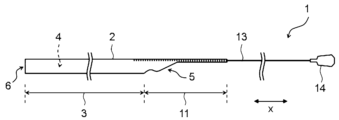
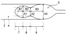
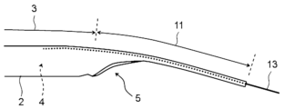
図1~図6を参照して、本発明の実施の形態に係る延長ガイドカテーテルについて説明する。図1は、本発明の実施の形態に係る延長ガイドカテーテルであって、延長ガイドカテーテルの全体図を表し、図2は、図1に示した延長ガイドカテーテルの筒状体の近位端部の側面図を表し、図3は、図2に示した延長ガイドカテーテルの筒状体の近位端部を下側から見た図を表し、図4は、図3に示した延長ガイドカテーテルの筒状体の近位端部の筒状体の拡大図を表し、図5は、図2に示した延長ガイドカテーテルの筒状体の近位端部であって、筒状体の近位端部を屈曲させた状態の側面図を表し、図6は、本発明の実施の形態に係る延長ガイドカテーテルを、血管内に配置されたガイドカテーテル内に挿入して、ガイドカテーテルの遠位側の開口から延出させた状態を示した図を表す。
An extension guide catheter according to an embodiment of the present invention will be described with reference to FIGS. 1 to 6. FIG. FIG. 1 is an extension guide catheter according to an embodiment of the present invention, showing an overall view of the extension guide catheter, and FIG. 2 is a view of the proximal end of the tubular body of the extension guide catheter shown in FIG. 3 shows a view from below of the proximal end of the tubular body of the extension guide catheter shown in FIG. 2, and FIG. 4 shows the tubular body of the extension guide catheter shown in FIG. 5 depicts an enlarged view of the tubular body at the proximal end of the tubular body, FIG. 5 is the proximal end of the tubular body of the extension guide catheter shown in FIG. is bent, and FIG. 6 shows that the extension guide catheter according to the embodiment of the present invention is inserted into the guide catheter placed in the blood vessel, and the opening on the distal side of the guide catheter is opened FIG. 10 shows a view showing a state extended from .
延長ガイドカテーテルは、ガイドカテーテルと組み合わせて用いられるものであり、具体的には、ガイドカテーテル内に挿入し、ガイドカテーテルの遠位側の開口から延出させて用いられるものである。延長ガイドカテーテルを用いることにより、血管内治療用器具等の処置デバイスをより末梢まで安定して送達することができる。血管内治療用器具としては、ステントやバルーン等が挙げられる。
The extension guide catheter is used in combination with the guide catheter. Specifically, it is inserted into the guide catheter and extended from the opening on the distal side of the guide catheter. By using the extension guide catheter, it is possible to stably deliver a treatment device such as an instrument for intravascular treatment to a farther periphery. Devices for endovascular treatment include stents and balloons.
図1および図2に示すように、本発明の実施の形態に係る延長ガイドカテーテル1は、長手軸方向xに延在する内腔4を有する筒状体2と、筒状体2に固定されており、筒状体2の近位側開口5より近位側に延在する線状部材13とを有する。
As shown in FIGS. 1 and 2, an extension guide catheter 1 according to an embodiment of the present invention includes a tubular body 2 having a lumen 4 extending in the longitudinal direction x, and a tube fixed to the tubular body 2. and a linear member 13 extending proximally from the proximal side opening 5 of the tubular body 2 .
延長ガイドカテーテル1は、図6に示すように、施術の際、先に体腔内に配置されているガイドカテーテル21内に挿入して用いられる。具体的には、延長ガイドカテーテル1を、ガイドカテーテル21の近位側の開口からガイドカテーテル21内に挿入し、ガイドカテーテル21の遠位側の開口22から延長ガイドカテーテル1を遠位側に延出させて用いられる。図6では、上行大動脈内に配置されたガイドカテーテル21内に延長ガイドカテーテル1が配置され、ガイドカテーテル21の遠位側の開口22から延長ガイドカテーテル1が延出した状態が示されている。
As shown in FIG. 6, the extension guide catheter 1 is used by inserting it into the guide catheter 21 previously placed in the body cavity during the operation. Specifically, the extension guide catheter 1 is inserted into the guide catheter 21 from the opening on the proximal side of the guide catheter 21, and the extension guide catheter 1 is extended distally from the opening 22 on the distal side of the guide catheter 21. It can be taken out and used. FIG. 6 shows a state in which the extension guide catheter 1 is placed inside the guide catheter 21 placed in the ascending aorta, and the extension guide catheter 1 extends from the opening 22 on the distal side of the guide catheter 21 .
延長ガイドカテーテル1は、線状部材13を押し込んだり引くことにより、ガイドカテーテル21内において筒状体2を前進または後退させたり、ガイドカテーテル21の遠位側の開口22から遠位側に延出させたり、ガイドカテーテル21内に引き戻すことができる。そして、血管内治療用器具等の処置デバイスを、ガイドカテーテル21および延長ガイドカテーテル1を通して送り出すことにより、処置デバイスを体腔内のより末端まで到達させることができる。ガイドカテーテル21の内径は、延長ガイドカテーテル1を受け入れるために、延長ガイドカテーテル1の外径よりも大きい。処置デバイスは、ガイドカテーテル21の近位側の開口からガイドカテーテル21内に入ってガイドカテーテル21内を通し、さらに延長ガイドカテーテル1の近位側開口5から延長ガイドカテーテル1内に入って延長ガイドカテーテル1内を通すことで、延長ガイドカテーテル1の筒状体2の遠位側開口6から遠位側に延出させることができる。
By pushing or pulling the linear member 13, the extension guide catheter 1 advances or retracts the cylindrical body 2 within the guide catheter 21, or extends distally from the distal opening 22 of the guide catheter 21. can be pulled back into the guide catheter 21. By delivering a treatment device such as an instrument for intravascular treatment through the guide catheter 21 and the extension guide catheter 1, the treatment device can reach a more distal end within the body cavity. The inner diameter of the guide catheter 21 is larger than the outer diameter of the extension guide catheter 1 to accommodate the extension guide catheter 1 . The treatment device enters the guide catheter 21 from the proximal side opening of the guide catheter 21, passes through the guide catheter 21, and further enters the extension guide catheter 1 from the proximal side opening 5 of the extension guide catheter 1 to be the extension guide. By passing it through the inside of the catheter 1, it can be extended distally from the distal side opening 6 of the tubular body 2 of the extension guide catheter 1. As shown in FIG.
延長ガイドカテーテル1において、長手軸方向xとは、延長ガイドカテーテル1の延在方向、具体的には筒状体2と線状部材13の延在方向として定められる。延長ガイドカテーテル1は、長手軸方向xに対する一方側と他方側として、近位側と遠位側を有する。延長ガイドカテーテル1において、近位側とは、延長ガイドカテーテル1の延在方向に対して使用者、つまり術者の手元側の方向を指し、遠位側とは近位側の反対方向、すなわち処置対象側の方向を指す。筒状体2は、長手軸方向xに対する直交方向として、径方向を有する。
In the extension guide catheter 1 , the longitudinal axis direction x is defined as the extension direction of the extension guide catheter 1 , specifically the extension direction of the tubular body 2 and the linear member 13 . The extension guide catheter 1 has a proximal side and a distal side as one side and the other side with respect to the longitudinal axis direction x. In the extension guide catheter 1, the proximal side refers to the direction toward the hand side of the user, that is, the operator with respect to the extending direction of the extension guide catheter 1, and the distal side is the opposite direction to the proximal side, that is, Point in the direction of the side to be treated. The cylindrical body 2 has a radial direction as a direction orthogonal to the longitudinal axis direction x.
延長ガイドカテーテル1の長手軸方向xの長さは、例えば、800mm以上が好ましく、1000mm以上がより好ましく、1200mm以上がさらに好ましく、また2200mm以下が好ましく、2000mm以下がより好ましく、1800mm以下がさらに好ましい。筒状体2の長手軸方向xの長さは、例えば、100mm以上が好ましく、200mm以上がより好ましく、250mm以上がさらに好ましく、また600mm以下が好ましく、500mm以下がより好ましく、450mm以下がさらに好ましい。
The length of the extension guide catheter 1 in the longitudinal direction x is, for example, preferably 800 mm or more, more preferably 1000 mm or more, still more preferably 1200 mm or more, and preferably 2200 mm or less, more preferably 2000 mm or less, and even more preferably 1800 mm or less. . The length of the cylindrical body 2 in the longitudinal direction x is, for example, preferably 100 mm or more, more preferably 200 mm or more, still more preferably 250 mm or more, preferably 600 mm or less, more preferably 500 mm or less, and even more preferably 450 mm or less. .
延長ガイドカテーテル1のガイドカテーテル内の挿通性や、延長ガイドカテーテル1内の処置デバイスの挿通性を確保する観点から、筒状体2の内腔4の直径は1.0mm以上が好ましく、1.2mm以上がより好ましく、1.3mm以上がさらに好ましく、また2.2mm以下が好ましく、2.0mm以下がより好ましく、1.9mm以下がさらに好ましい。筒状体2の外径は1.2mm以上が好ましく、1.3mm以上がより好ましく、1.4mm以上がさらに好ましく、また3.5mm以下が好ましく、3.0mm以下がより好ましく、2.5mm以下がさらに好ましい。筒状体2の肉厚は、0.01mm以上が好ましく、0.02mm以上がより好ましく、0.05mm以上がさらに好ましく、また0.4mm以下が好ましく、0.3mm以下がより好ましく、0.2mm以下がさらに好ましい。
From the viewpoint of ensuring the insertability of the extension guide catheter 1 through the guide catheter and the insertability of the treatment device inside the extension guide catheter 1, the diameter of the lumen 4 of the cylindrical body 2 is preferably 1.0 mm or more. 2 mm or more is more preferable, 1.3 mm or more is still more preferable, 2.2 mm or less is preferable, 2.0 mm or less is more preferable, and 1.9 mm or less is even more preferable. The outer diameter of the cylindrical body 2 is preferably 1.2 mm or more, more preferably 1.3 mm or more, still more preferably 1.4 mm or more, and preferably 3.5 mm or less, more preferably 3.0 mm or less, and 2.5 mm. More preferred are: The thickness of the cylindrical body 2 is preferably 0.01 mm or more, more preferably 0.02 mm or more, still more preferably 0.05 mm or more, and preferably 0.4 mm or less, more preferably 0.3 mm or less, and 0.01 mm or more. 2 mm or less is more preferable.
筒状体2の長手軸方向xに対する垂直断面において、筒状体2の内腔4の形状や、筒状体2の外縁の形状は特に限定されず、円形、楕円形、長円形、多角形、不定形等が挙げられる。筒状体2の内腔4の形状や外縁の形状が円形以外の場合、上記に説明した筒状体2の内腔4の直径と筒状体2の外径は、円相当径を意味する。すなわち筒状体2の内腔4の周長または筒状体2の外縁の周長と同じ長さの円周の円の直径を意味する。なお、筒状体2の内腔4の形状と筒状体2の外縁の形状は、円形または楕円形であることが好ましく、楕円形の場合は、短径/長径の比が0.80以上であることが好ましく、0.90以上がより好ましく、0.95以上がさらに好ましい。
In the cross section perpendicular to the longitudinal axis direction x of the tubular body 2, the shape of the lumen 4 of the tubular body 2 and the shape of the outer edge of the tubular body 2 are not particularly limited, and may be circular, elliptical, oval, or polygonal. , irregular shapes, and the like. When the shape of the lumen 4 and the shape of the outer edge of the tubular body 2 are other than circular, the diameter of the lumen 4 of the tubular body 2 and the outer diameter of the tubular body 2 described above mean equivalent circle diameters. . That is, it means the diameter of a circle having the same length as the circumference of the lumen 4 of the tubular body 2 or the circumference of the outer edge of the tubular body 2 . The shape of the lumen 4 of the cylindrical body 2 and the shape of the outer edge of the cylindrical body 2 are preferably circular or elliptical. is preferred, 0.90 or more is more preferred, and 0.95 or more is even more preferred.
筒状体2は、例えば樹脂から構成することができる。樹脂としては、例えば、ポリアミド樹脂、ポリエステル樹脂、ポリウレタン樹脂、ポリオレフィン樹脂、フッ素系樹脂、塩化ビニル系樹脂、シリコーン樹脂、および天然ゴム等が挙げられる。ポリアミド樹脂としては、ナイロン12、ナイロン12エラストマー、ナイロン6、芳香族ポリアミド等が挙げられる。ポリエステル樹脂としては、ポリエチレンテレフタレート等が挙げられる。ポリウレタン樹脂としては、脂肪族イソシアネートをモノマー単位として含む脂肪族ポリウレタン、芳香族イソシアネートをモノマー単位として含む芳香族ポリウレタン等が挙げられる。ポリオレフィン樹脂としては、ポリエチレン、ポリプロピレン等が挙げられる。フッ素系樹脂としては、ポリテトラフルオロエチレン、エチレンテトラフルオロエチレン、フッ素化エチレンプロピレン等が挙げられる。塩化ビニル系樹脂としては、ポリ塩化ビニル、ポリ塩化ビニリデン等が挙げられる。シリコーン樹脂としては、ジメチルポリシロキサン、メチルフェニルポリシロキサン、メチルビニルポリシロキサン、フロロアルキルメチルポリシロキサン等が挙げられる。天然ゴムとしては、ラテックス等が挙げられる。
The cylindrical body 2 can be made of resin, for example. Examples of resins include polyamide resins, polyester resins, polyurethane resins, polyolefin resins, fluorine-based resins, vinyl chloride-based resins, silicone resins, and natural rubber. Polyamide resins include nylon 12, nylon 12 elastomer, nylon 6, aromatic polyamides, and the like. Polyethylene terephthalate etc. are mentioned as a polyester resin. Examples of polyurethane resins include aliphatic polyurethanes containing aliphatic isocyanates as monomer units, aromatic polyurethanes containing aromatic isocyanates as monomer units, and the like. Examples of polyolefin resins include polyethylene and polypropylene. Examples of the fluororesin include polytetrafluoroethylene, ethylenetetrafluoroethylene, fluorinated ethylenepropylene, and the like. Examples of vinyl chloride-based resins include polyvinyl chloride and polyvinylidene chloride. Examples of silicone resins include dimethylpolysiloxane, methylphenylpolysiloxane, methylvinylpolysiloxane, and fluoroalkylmethylpolysiloxane. Latex etc. are mentioned as natural rubber.
筒状体2は、単層から構成されていてもよく、複数層から構成されていてもよい。また、長手軸方向xにおいて、筒状体2の一部が単層から構成されており、他部が複数層から構成されていてもよい。
The tubular body 2 may be composed of a single layer, or may be composed of multiple layers. Moreover, in the longitudinal direction x, part of the cylindrical body 2 may be composed of a single layer, and the other part may be composed of multiple layers.
筒状体2は、補強層を有することが好ましい。補強層により、筒状体2の剛性を高めることができる。補強層は、筒状体2の内側面に設けてもよく、外側面に設けてもよく、筒状体2の内側面と外側面の間に設けてもよい。
The tubular body 2 preferably has a reinforcing layer. The reinforcement layer can increase the rigidity of the cylindrical body 2 . The reinforcing layer may be provided on the inner surface of the tubular body 2 , may be provided on the outer surface, or may be provided between the inner and outer surfaces of the tubular body 2 .
補強層は、金属線や繊維等から構成することができる。金属線を構成する素材としては、例えば、ステンレス鋼、チタン、ニッケルチタン合金、コバルトクロム合金、タングステン合金等が挙げられる。なかでも、ステンレス鋼が好ましい。金属線は、単線であってもよいし、撚線であってもよい。繊維としては、例えば、ポリアリレート繊維、アラミド繊維、超高分子量ポリエチレン繊維、PBO(ポリパラフェニレンベンズオキサゾール)繊維、炭素繊維等が挙げられる。繊維は、モノフィラメントであってもよいし、マルチフィラメントであってもよい。
The reinforcing layer can be composed of metal wires, fibers, or the like. Materials constituting the metal wire include, for example, stainless steel, titanium, nickel-titanium alloys, cobalt-chromium alloys, and tungsten alloys. Among them, stainless steel is preferable. The metal wire may be a single wire or a twisted wire. Examples of fibers include polyarylate fibers, aramid fibers, ultra-high molecular weight polyethylene fibers, PBO (polyparaphenylenebenzoxazole) fibers, and carbon fibers. The fibers may be monofilaments or multifilaments.
補強層の形状は、特に限定されないが、らせん状、網目状、編組状が好ましい。なかでも、補強層によって筒状体2の剛性を効果的に高めることができる点から、補強層の形状は編組状であることがより好ましい。
Although the shape of the reinforcing layer is not particularly limited, it is preferably spiral, mesh, or braided. In particular, the shape of the reinforcing layer is more preferably braided because the reinforcing layer can effectively increase the rigidity of the cylindrical body 2 .
筒状体2は、X線透視下等の位置を確認しやすくするために、放射線不透過物質を含んでいてもよい。放射線不透過物質としては、例えば、鉛、バリウム、ヨウ素、タングステン、金、白金、イリジウム、白金イリジウム合金、ステンレス、チタン、コバルトクロム合金、パラジウム、タンタル等が挙げられる。例えば、筒状体2の近位端部や遠位端部に放射線不透過マーカーが設けられることが好ましく、これにより、X線透視下で体腔内における筒状体2の位置を確認することができる。
The cylindrical body 2 may contain a radiopaque material in order to facilitate confirmation of the position under X-ray fluoroscopy. Radiopaque materials include, for example, lead, barium, iodine, tungsten, gold, platinum, iridium, platinum-iridium alloys, stainless steel, titanium, cobalt-chromium alloys, palladium, tantalum, and the like. For example, radiopaque markers are preferably provided at the proximal end and the distal end of the tubular body 2, so that the position of the tubular body 2 within the body cavity can be confirmed under X-ray fluoroscopy. can.
筒状体2は、外側面が親水性ポリマーによりコーティングされていてもよい。これにより筒状体2のガイドカテーテル内や血管内への挿入を容易にすることができる。親水性ポリマーとして、例えば、ポリ2-ヒドロキシエチルメタアクリレート、ポリアクリルアミド、ポリビニルピロリドン、メチルビニルエーテル無水マレイン酸共重合体等の無水マレイン酸共重合体等の親水性ポリマーが挙げられる。
The cylindrical body 2 may have its outer surface coated with a hydrophilic polymer. This facilitates insertion of the cylindrical body 2 into the guide catheter or blood vessel. Examples of hydrophilic polymers include hydrophilic polymers such as poly-2-hydroxyethyl methacrylate, polyacrylamide, polyvinylpyrrolidone, and maleic anhydride copolymers such as methyl vinyl ether maleic anhydride copolymers.
筒状体2は、内層と外層を有することが好ましい。内層と外層は上記に説明した樹脂から構成することができる。なかでも、内層は、ポリエステル樹脂、ポリオレフィン樹脂、フッ素系樹脂、シリコーン樹脂、および天然ゴムよりなる群から選ばれる少なくとも1種から構成されることが好ましい。特に、耐薬品性、非粘着性、低摩擦性に優れる点から、内層はフッ素系樹脂から構成されることが好ましい。外層は、ポリアミド樹脂、ポリウレタン樹脂、およびポリオレフィン樹脂よりなる群から選ばれる少なくとも1種の樹脂から構成されることが好ましく、ポリアミド樹脂およびポリウレタン樹脂よりなる群から選ばれる少なくとも1種の樹脂から構成されることがより好ましく、ポリウレタン樹脂から構成されることがさらに好ましい。
The tubular body 2 preferably has an inner layer and an outer layer. The inner and outer layers can be composed of the resins described above. Among others, the inner layer is preferably composed of at least one selected from the group consisting of polyester resins, polyolefin resins, fluororesins, silicone resins, and natural rubbers. In particular, from the viewpoint of excellent chemical resistance, non-adhesiveness, and low friction, the inner layer is preferably composed of a fluororesin. The outer layer is preferably composed of at least one resin selected from the group consisting of polyamide resins, polyurethane resins, and polyolefin resins, and is composed of at least one resin selected from the group consisting of polyamide resins and polyurethane resins. More preferably, it is made of a polyurethane resin.
筒状体2は、内層と外層に加えて補強層を有することが好ましい。補強層は、外層に設けてもよく、内層に設けてもよく、内層と外層の間に設けてもよいが、筒状体2の強度を高めることが容易な点から、補強層は内層と外層の間に設けられることが好ましい。
The tubular body 2 preferably has a reinforcing layer in addition to the inner layer and the outer layer. The reinforcing layer may be provided on the outer layer, on the inner layer, or between the inner layer and the outer layer. It is preferably provided between outer layers.
線状部材13は長尺状の線材であり、筒状体2の近位端部に固定される。線状部材13を押し込んだり引くことにより、筒状体2を前進または後退させることができ、これにより、筒状体2をガイドカテーテルの遠位側の開口から突出させたり、筒状体2をガイドカテーテル内に引き戻すことができる。
The linear member 13 is an elongated wire and fixed to the proximal end of the cylindrical body 2 . By pushing or pulling the linear member 13, the tubular body 2 can be advanced or retracted, thereby causing the tubular body 2 to protrude from the opening on the distal side of the guide catheter or to move the tubular body 2 forward. It can be pulled back into the guide catheter.
線状部材13は金属から構成されることが好ましい。線状部材13を構成する金属としては、例えば、ステンレス鋼、チタン、ニッケルチタン合金、コバルトクロム合金、タングステン合金等が挙げられ、なかでもステンレス鋼がより好ましい。線状部材13の長手軸方向xに対する垂直方向の断面形状は特に限定されず、例えば、正方形、長方形、台形等の四角形、四角形以外の多角形、円形、楕円形、長円形等が挙げられる。なかでも、線状部材13の断面形状は四角形であることが好ましい。
The linear member 13 is preferably made of metal. Examples of the metal forming the linear member 13 include stainless steel, titanium, nickel-titanium alloys, cobalt-chromium alloys, tungsten alloys, etc. Among them, stainless steel is more preferable. The cross-sectional shape of the linear member 13 in the direction perpendicular to the longitudinal axis direction x is not particularly limited. Especially, it is preferable that the cross-sectional shape of the linear member 13 is a square.
延長ガイドカテーテル1は、線状部材13の近位端部に把持部材14が設けられることが好ましい。施術者が把持部材14を指で把持することにより、延長ガイドカテーテル1を押し込んだり引く操作を行うことが容易になる。把持部材14を構成する素材として樹脂が挙げられ、樹脂としてポリエチレン、ポリプロピレン等のポリオレフィン樹脂が挙げられる。
The extension guide catheter 1 is preferably provided with a grasping member 14 at the proximal end of the linear member 13 . By gripping the gripping member 14 with fingers, the operator can easily push in and pull out the extension guide catheter 1 . Examples of materials for the grip member 14 include resins, and examples of resins include polyolefin resins such as polyethylene and polypropylene.
線状部材13は、筒状体2の内側面に固定されてもよく、筒状体2の外側面に固定されてもよく、筒状体2の内側面と外側面の間に固定されてもよい。筒状体2が内層と外層を有する場合は、線状部材13は筒状体2の内層に固定されてもよく、外層に固定されてもよく、内層と外層の間に固定されてもよい。線状部材13は、筒状体2の径方向の一方側に固定され、筒状体2は、径方向に対して、線状部材13が固定された側が上側、その反対側が下側と規定される。すなわち、筒状体2は、径方向に対して、線状部材13が固定されている上側と、その反対側の下側を有する。また、径方向のうち、上側から下側に延びる方向を上下方向と称し、それに直交する方向を幅方向と称する。
The linear member 13 may be fixed to the inner surface of the tubular body 2, may be fixed to the outer surface of the tubular body 2, or may be fixed between the inner and outer surfaces of the tubular body 2. good too. When the cylindrical body 2 has an inner layer and an outer layer, the linear member 13 may be fixed to the inner layer of the cylindrical body 2, the outer layer, or between the inner layer and the outer layer. . The linear member 13 is fixed to one side of the cylindrical body 2 in the radial direction, and the cylindrical body 2 is defined such that the side to which the linear member 13 is fixed is the upper side and the opposite side is the lower side with respect to the radial direction. be done. That is, the cylindrical body 2 has an upper side to which the linear member 13 is fixed and a lower side opposite to the upper side with respect to the radial direction. In addition, among the radial directions, the direction extending from the upper side to the lower side is referred to as the vertical direction, and the direction orthogonal thereto is referred to as the width direction.
筒状体2は、近位側開口5と遠位側開口6を有する。筒状体2の近位側開口5とは、筒状体2の内腔4の近位側の開口を意味し、筒状体2の遠位側開口6とは、筒状体2の内腔4の遠位側の開口を意味する。なお、筒状体2の近位側開口5は長手軸方向xに対して傾斜した部分を有する。筒状体2は、筒状に形成された筒状部分3と、筒状部分3から近位側に延びる非筒状の近位延出部分11を有し、近位側開口5の外縁が近位延出部分11に形成される。筒状体2の内腔4は筒状部分3に形成される。
The cylindrical body 2 has a proximal opening 5 and a distal opening 6. The proximal opening 5 of the tubular body 2 means the opening on the proximal side of the lumen 4 of the tubular body 2 , and the distal opening 6 of the tubular body 2 means the inside of the tubular body 2 . It means the distal opening of cavity 4 . The proximal side opening 5 of the cylindrical body 2 has a portion inclined with respect to the longitudinal axis direction x. The cylindrical body 2 has a cylindrical portion 3 formed in a cylindrical shape and a non-cylindrical proximal extension portion 11 extending proximally from the cylindrical portion 3, and the outer edge of the proximal side opening 5 is It is formed on the proximal extension portion 11 . A bore 4 of the tubular body 2 is formed in the tubular portion 3 .
近位側開口5は、長手軸方向xに対して、第1区間7と、第1区間7よりも近位側の第2区間8と、第2区間8よりも近位側の第3区間9を有する。筒状体2において、近位側開口5の外縁が形成された近位延出部分11、具体的には近位延出部分11のうち第1区間7~第3区間9が形成された長手軸方向xの範囲の部分と、その遠位側に隣接する部分を、筒状体2の近位端部と称する。例えば、近位延出部分11のうち第1区間7~第3区間9が形成された部分と、それに隣接する筒状部分3の近位端から遠位側に20mm以内の部分を、筒状体2の近位端部とすることができる。また、近位延出部分11において、第1区間7が形成された長手軸方向xの範囲の部分を、近位延出部分11の第1区間7と称する。近位延出部分11の第1区間7よりも近位側の部分についても、同様に各区間に基づき長手軸方向xに対する部分が規定される。
The proximal opening 5 has a first section 7, a second section 8 proximal to the first section 7, and a third section proximal to the second section 8 with respect to the longitudinal axis direction x. 9. In the tubular body 2, a proximal extension portion 11 formed with the outer edge of the proximal side opening 5, specifically, a longitudinal portion in which the first section 7 to the third section 9 of the proximal extension portion 11 are formed A portion within the range in the axial direction x and a portion adjacent to the distal side thereof are referred to as a proximal end portion of the tubular body 2 . For example, the portion of the proximal extension portion 11 in which the first section 7 to the third section 9 are formed and the portion within 20 mm distally from the proximal end of the tubular portion 3 adjacent thereto are formed into a tubular shape. It can be the proximal end of body 2 . Also, in the proximal extension portion 11 , the portion of the longitudinal axis direction x where the first section 7 is formed is referred to as the first section 7 of the proximal extension portion 11 . Similarly, for the portion of the proximal extension portion 11 that is closer to the proximal side than the first section 7, the section with respect to the longitudinal axis direction x is defined based on each section.
図3に示すように、筒状体2を下側から見て、近位側開口5は、第1区間7において遠位側から近位側に向かって幅が漸増し、第2区間8において遠位側から近位側に向かって幅が漸減し、第3区間9において遠位側から近位側に向かって幅が漸増するように形成されている。本発明の実施の形態に係る延長ガイドカテーテル1は、このように筒状体2の近位側開口5が形成されることにより、筒状体2の近位端部が血管等の体腔の屈曲部分やガイドカテーテルの屈曲部分に位置したときに、近位側開口5の大きさが広がるように筒状体2が変形し、血管内治療用器具等の処置デバイスを、筒状体2の近位側開口5から筒状体2の内腔4内に挿入することが容易になる。
As shown in FIG. 3 , when the tubular body 2 is viewed from below, the width of the proximal opening 5 gradually increases from the distal side to the proximal side in the first section 7 and increases in the second section 8 . The width gradually decreases from the distal side to the proximal side, and the width of the third section 9 gradually increases from the distal side to the proximal side. In the extension guide catheter 1 according to the embodiment of the present invention, the proximal opening 5 of the tubular body 2 is formed in this way, so that the proximal end portion of the tubular body 2 is bent in a body cavity such as a blood vessel. The tubular body 2 is deformed so that the size of the proximal side opening 5 expands when positioned at a bent portion of the guide catheter, and a treatment device such as an endovascular treatment instrument is placed near the tubular body 2. It becomes easy to insert into the lumen 4 of the cylindrical body 2 from the position side opening 5 .
これについて詳しく説明すると、延長ガイドカテーテル1はガイドカテーテルおよび体腔内に挿入して用いられるが、処置デバイスをガイドカテーテルから延長ガイドカテーテル1を通して送り出すのに当たり、延長ガイドカテーテル1を体腔内の所望の位置にセットした際、筒状体2の近位端部が体腔やガイドカテーテルの屈曲部分に位置する場合がある。この場合、体腔やガイドカテーテルの屈曲部分に沿って、筒状体2の近位端部が、筒状体2の下側を内側にして屈曲するが、これにより、筒状体2の内腔4が潰れたり、内腔4の断面形状が歪んで断面積が狭まることが懸念される。しかし、延長ガイドカテーテル1は、上記のように近位側開口5に第1区間7と第2区間8と第3区間9が形成されているため、筒状体2の近位端部が体腔やガイドカテーテルの屈曲部分に位置した際に、筒状体2の近位端部に曲げ方向の力が加わると、筒状体2が、下側から見て近位側開口5が開くように変形し、近位側開口5の大きさが広がる。また、筒状体2の近位端部が屈曲しても、当該部分で歪みが生じにくく、筒状体2の内腔4が潰れたり、内腔4の断面形状が歪んで断面積が大きく狭まることが抑えられる。そのため、処置デバイスを、筒状体2の近位側開口5から筒状体2の内腔4内に挿入することが容易になる。
To explain this in detail, the extension guide catheter 1 is used by inserting it into the guide catheter and the body cavity. , the proximal end of the tubular body 2 may be located in a body cavity or a bent portion of the guide catheter. In this case, the proximal end of the tubular body 2 is bent with the lower side of the tubular body 2 inside along the bent portion of the body cavity or the guide catheter. 4 may be crushed, or the cross-sectional shape of the lumen 4 may be distorted to narrow the cross-sectional area. However, since the extension guide catheter 1 has the first section 7, the second section 8, and the third section 9 formed in the proximal side opening 5 as described above, the proximal end of the cylindrical body 2 extends into the body cavity. or at the bent portion of the guide catheter, when a force in the bending direction is applied to the proximal end of the tubular body 2, the tubular body 2 opens the proximal side opening 5 when viewed from below. It deforms and the size of the proximal side opening 5 expands. In addition, even if the proximal end portion of the cylindrical body 2 is bent, distortion is unlikely to occur in this portion, and the lumen 4 of the cylindrical body 2 may be crushed or the cross-sectional shape of the lumen 4 may be distorted to increase the cross-sectional area. Narrowing can be suppressed. Therefore, it becomes easier to insert the treatment device into the lumen 4 of the tubular body 2 from the proximal opening 5 of the tubular body 2 .
例えば、図7に示すように、近位側開口5の外縁が単に長手軸方向xに対して斜めに延びるように形成される場合は、筒状体2の近位端部が屈曲すると、図8に示すように、近位側開口5の遠位端に歪みが生じ、いびつな形で内側に折れ曲がりやすくなる。その結果、筒状体2の内腔4の下側部分に歪みが生じ、内腔4の断面積が狭まり、筒状体2の近位側開口5に処置デバイスを挿入することに支障を来すおそれがある。これに対して、近位側開口5に第1区間7と第2区間8と第3区間9を設けた場合は、近位延出部分11の第3区間9に曲げ方向の力が加わると、その力が第2区間8に伝わり、図5に示すように、第2区間8で近位側開口5の下側部分が開くように変形することができる。また、近位延出部分11は、第1区間7から第2区間8にかけて容易に屈曲することができるが、その際、当該屈曲に伴い、第2区間8から第3区間に9にかけて近位側開口5の下側部分が開くように変形することができる。さらに、近位延出部分11が第1区間7から第2区間8にかけて屈曲しても、当該部分で歪みが生じることが起こりにくく、筒状体2の近位端部をより大きい曲率で屈曲させることができる。そして、第1区間7から第2区間8にかけて近位側開口5が幅広に形成されているため、第2区間8から第3区間9にかけて近位側開口5の下側部分が開くように変形することにより、筒状体2の下側に大きな開口が形成される。そのため、処置デバイスを筒状体2の近位側開口5から挿入する際に、処置デバイスが筒状体2の近位側開口5の外縁に引っ掛かりにくく、処置デバイスを筒状体2の近位側開口5に挿入することが容易になる。
For example, as shown in FIG. 7, when the outer edge of the proximal side opening 5 is formed to simply extend obliquely with respect to the longitudinal axis direction x, when the proximal end portion of the cylindrical body 2 is bent, As shown in 8, the distal end of the proximal opening 5 is distorted and tends to bend inward in a distorted shape. As a result, the lower portion of the lumen 4 of the tubular body 2 is distorted, the cross-sectional area of the lumen 4 is narrowed, and the insertion of the treatment device into the proximal opening 5 of the tubular body 2 is hindered. There is a risk of On the other hand, when the proximal opening 5 is provided with the first section 7, the second section 8, and the third section 9, when the force in the bending direction is applied to the third section 9 of the proximal extension portion 11, , the force is transmitted to the second section 8, which can be deformed so that the lower portion of the proximal opening 5 opens at the second section 8, as shown in FIG. In addition, the proximal extension portion 11 can be easily bent from the first section 7 to the second section 8, and at that time, along with the bending, the proximal extension portion 11 can be bent from the second section 8 to the third section 9. The lower part of the side opening 5 can be deformed to open. Furthermore, even if the proximal extension portion 11 is bent from the first section 7 to the second section 8, distortion is less likely to occur in this section, and the proximal end portion of the tubular body 2 is bent with a larger curvature. can be made Since the proximal opening 5 is widened from the first section 7 to the second section 8, the lower portion of the proximal opening 5 opens from the second section 8 to the third section 9. By doing so, a large opening is formed on the lower side of the tubular body 2 . Therefore, when the treatment device is inserted from the proximal opening 5 of the tubular body 2 , the treatment device is less likely to be caught on the outer edge of the proximal opening 5 of the tubular body 2 , and the treatment device is inserted proximally of the tubular body 2 . Insertion into the side opening 5 is facilitated.
近位側開口5の幅は、筒状体2を下側から見たときの近位側開口5の外縁の投影形状に基づき定められ、長手軸方向xと上下方向に直交する方向、すなわち幅方向に対する近位側開口5の外縁の両端間の長さを計測することにより求められる。近位側開口5の外縁は、筒状体2の下側から見たときに、直線状に形成されていてもよく、曲線状に形成されていてもよく、これらの組み合わせの形状で形成されていてもよい。
The width of the proximal side opening 5 is determined based on the projected shape of the outer edge of the proximal side opening 5 when the cylindrical body 2 is viewed from below, and the width It is obtained by measuring the length between both ends of the outer edge of the proximal opening 5 with respect to the direction. The outer edge of the proximal opening 5, when viewed from the bottom side of the tubular body 2, may be formed in a straight line shape, may be formed in a curved shape, or may be formed in a combination of these shapes. may be
第1区間7から第3区間9において、近位側開口5の外縁は、幅方向に線対称に形成されていることが好ましい。この場合、近位側開口5の幅は、近位側開口5の長手軸方向xの垂直断面において、上下方向の同じ位置における近位側開口5の外縁の両端間の幅方向の長さを計測することにより求めることができる。このように近位側開口5が形成されていれば、筒状体2の近位端部が体腔やガイドカテーテルの屈曲部分に位置した際に、筒状体2の近位端部が大きな歪みを生じることなくスムーズに屈曲しやすくなる。また筒状体2の近位端部が屈曲した際に、近位側開口5が幅方向の一方側と他方側で略均等に幅方向に広がりやすくなる。なお、幅方向に線対称に形成されるとは、長手軸方向xと上下方向により規定される平面に対して、対称に形成されることを意味する。
From the first section 7 to the third section 9, the outer edge of the proximal side opening 5 is preferably formed line-symmetrically in the width direction. In this case, the width of the proximal opening 5 is the length in the width direction between both ends of the outer edge of the proximal opening 5 at the same position in the vertical direction in the vertical cross section of the proximal opening 5 in the longitudinal axis direction x. It can be obtained by measuring. If the proximal side opening 5 is formed in this way, the proximal end portion of the tubular body 2 is greatly distorted when the proximal end portion of the tubular body 2 is positioned in the body cavity or the bent portion of the guide catheter. It becomes easy to bend smoothly without causing Further, when the proximal end portion of the cylindrical body 2 is bent, the proximal side opening 5 tends to expand substantially evenly in the width direction on one side and the other side in the width direction. In addition, forming symmetrically in the width direction means forming symmetrically with respect to a plane defined by the longitudinal axis direction x and the vertical direction.
近位側開口5は、第1区間7の遠位端が、近位側開口5の遠位端となることが好ましい。従って、第1区間7は、近位側開口5の遠位端を含んで形成されることが好ましい。一方、近位側開口5は、第3区間9の近位端よりも近位側にも存在していてもよく、例えば、第3区間9よりも近位側に、遠位側から近位側に向かって幅が漸減するように形成された第4区間10を有していてもよい。
The distal end of the first section 7 of the proximal opening 5 is preferably the distal end of the proximal opening 5 . Therefore, first section 7 is preferably formed including the distal end of proximal opening 5 . On the other hand, the proximal opening 5 may also be present on the proximal side of the proximal end of the third section 9, for example, on the proximal side of the third section 9, from the distal side to the proximal side. You may have the 4th section 10 formed so that width may taper toward a side.
近位側開口5の外縁は、第1区間7の遠位端から第2区間8の近位端において、筒状体2の下側半分の部分に形成されることが好ましい。これにより、筒状体2の近位端部が体腔やガイドカテーテルの屈曲部分に位置した際に、近位延出部分11が第1区間7から第2区間8にかけて過度に大きく屈曲することを抑えることができる。そのため、処置デバイスを近位側開口5から挿入する際に、処置デバイスが近位側開口5の外縁に引っ掛かることを抑えることができる。また、近位延出部分11の第3区間9に曲げ方向の力が加わりやすくなり、その力が第2区間8に伝わって、第2区間8で近位側開口5の下側部分が開くように変形しやすくなる。あるいは、近位延出部分11の第1区間7から第2区間8にかけての屈曲に伴い、第2区間8から第3区間に9にかけて近位側開口5の下側部分が開くように変形しやすくなる。
The outer edge of the proximal opening 5 is preferably formed in the lower half portion of the cylindrical body 2 from the distal end of the first section 7 to the proximal end of the second section 8 . This prevents the proximal extension portion 11 from excessively bending from the first section 7 to the second section 8 when the proximal end portion of the cylindrical body 2 is positioned in a body cavity or a bent portion of the guide catheter. can be suppressed. Therefore, when inserting the treatment device through the proximal opening 5 , it is possible to prevent the treatment device from being caught on the outer edge of the proximal opening 5 . In addition, force in the bending direction is likely to be applied to the third section 9 of the proximal extension portion 11, the force is transmitted to the second section 8, and the lower portion of the proximal side opening 5 is opened in the second section 8. It becomes easy to transform like this. Alternatively, as the proximal extension portion 11 is bent from the first section 7 to the second section 8, the lower portion of the proximal side opening 5 is deformed from the second section 8 to the third section 9 so that the lower portion opens. easier.
近位側開口5の外縁は、第3区間9においても、筒状体2の下側半分の部分に形成されることが好ましい。従って、近位側開口5の外縁は、第1区間7から第3区間9において、筒状体2の下側半分の部分に形成されることが好ましい。この場合、第3区間9の近位端は、筒状体2の下側半分の部分の近位端に一致することが好ましい。また、第3区間9の近位側の第4区間10では、近位側開口5の外縁は筒状体2の上側半分の部分に形成されることが好ましい。
The outer edge of the proximal opening 5 is preferably formed in the lower half portion of the tubular body 2 also in the third section 9 . Therefore, the outer edge of the proximal opening 5 is preferably formed in the lower half portion of the cylindrical body 2 in the first section 7 to the third section 9 . In this case, the proximal end of the third section 9 preferably coincides with the proximal end of the lower half portion of the tubular body 2 . Moreover, in the fourth section 10 on the proximal side of the third section 9 , the outer edge of the proximal opening 5 is preferably formed in the upper half portion of the tubular body 2 .
第1区間7の遠位端から第2区間8の近位端までの長手軸方向xの長さは、第3区間9の近位端における近位側開口5の幅の0.3倍以上であることが好ましく、0.6倍以上がより好ましく、1倍以上がさらに好ましい。これにより、筒状体2の近位端部が屈曲した際に、近位側開口5の下側部分が広がるようにスムーズに変形しやすくなる。また、近位側開口5の下側部分が開いた際に、処置デバイスが筒状体2の近位側開口5の外縁、特に近位延出部分11の第2区間8から第3区間9にかけての突き出た部分に引っ掛かりにくくなる。一方、第1区間7の遠位端から第2区間8の近位端までの長手軸方向xの長さは、第3区間9の近位端における近位側開口5の幅の15倍以下であることが好ましく、12倍以下がより好ましく、10倍以下がさらに好ましい。これにより、近位延出部分11の第1区間7と第2区間8の長手軸方向xの長さが過剰に長く形成されず、筒状体2の近位端部が体腔やガイドカテーテルの屈曲部分に位置した際に、近位延出部分11の第3区間9に曲げ方向の力がかかりやすくなる。そのため、近位延出部分11の第3区間9に加わった力が第2区間8に伝わって、第2区間8で近位側開口5の下側部分が開くように変形しやすくなる。
The length in the longitudinal direction x from the distal end of the first section 7 to the proximal end of the second section 8 is 0.3 times or more the width of the proximal side opening 5 at the proximal end of the third section 9 is preferred, 0.6 times or more is more preferred, and 1 time or more is even more preferred. As a result, when the proximal end portion of the cylindrical body 2 is bent, the lower portion of the proximal side opening 5 can be smoothly deformed so as to widen. In addition, when the lower portion of the proximal opening 5 is opened, the treatment device moves toward the outer edge of the proximal opening 5 of the tubular body 2, particularly the second section 8 to the third section 9 of the proximal extending portion 11. It becomes difficult to get caught on the protruding part. On the other hand, the length of the longitudinal axis direction x from the distal end of the first section 7 to the proximal end of the second section 8 is 15 times or less the width of the proximal opening 5 at the proximal end of the third section 9. is preferred, 12 times or less is more preferred, and 10 times or less is even more preferred. As a result, the lengths of the first section 7 and the second section 8 in the longitudinal axis direction x of the proximal extension portion 11 are not excessively long, and the proximal end portion of the tubular body 2 is positioned in a body cavity or a guide catheter. When positioned at the bent portion, the force in the bending direction is likely to be applied to the third section 9 of the proximal extension portion 11 . Therefore, the force applied to the third section 9 of the proximal extension portion 11 is transmitted to the second section 8 , and the second section 8 easily deforms so that the lower portion of the proximal side opening 5 opens.
第1区間7の長手軸方向xの長さ、および/または、第2区間8の長手軸方向xの長さは、第3区間9の長手軸方向xの長さ以下であることが好ましい。このように近位側開口5が形成されていれば、近位延出部分11が第1区間7から第2区間8にかけて屈曲した際に、当該部分で歪みが生じにくくなる。そのため、処置デバイスを筒状体2の近位側開口5から挿入する際に、処置デバイスが筒状体2の近位側開口5の外縁に引っ掛かりにくくなる。この場合、第1区間7の長手軸方向xの長さと第2区間8の長手軸方向xの長さは、どちらか一方が第3区間9の長手軸方向xの長さよりも長くなってもよいが、その場合は、第3区間9の長手軸方向xの長さの2.0倍以下であることが好ましく、1.5倍以下がより好ましい。また、第1区間7の長手軸方向xの長さと第2区間8の長手軸方向xの長さの両方が、第3区間9の長手軸方向xの長さ以下となってもよい。
The length of the first section 7 in the longitudinal direction x and/or the length of the second section 8 in the longitudinal direction x is preferably equal to or less than the length of the third section 9 in the longitudinal direction x. If the proximal side opening 5 is formed in this way, when the proximal extending portion 11 is bent from the first section 7 to the second section 8, distortion is less likely to occur in that portion. Therefore, when inserting the treatment device from the proximal opening 5 of the tubular body 2 , the treatment device is less likely to get caught on the outer edge of the proximal opening 5 of the tubular body 2 . In this case, even if one of the length in the longitudinal axis direction x of the first section 7 and the length in the longitudinal axis direction x of the second section 8 is longer than the length in the longitudinal axis direction x of the third section 9 . However, in that case, it is preferably 2.0 times or less, more preferably 1.5 times or less, the length of the third section 9 in the longitudinal direction x. Also, both the length in the longitudinal axis direction x of the first section 7 and the length in the longitudinal axis direction x of the second section 8 may be less than or equal to the length in the longitudinal axis direction x of the third section 9 .
第3区間9の遠位端における近位側開口5の幅は、第3区間9の近位端における近位側開口5の幅の0.3倍以上であることが好ましく、0.4倍以上がより好ましく、0.5倍以上がさらに好ましい。このように近位側開口5が形成されていれば、処置デバイスを筒状体2の近位側開口5から挿入する際に、処置デバイスが、近位延出部分11の第2区間8から第3区間9にかけての突き出た部分に引っ掛かりにくくなる。一方、第3区間9の遠位端における近位側開口5の幅は、第3区間9の近位端における近位側開口5の幅の0.9倍以下であることが好ましく、これにより第3区間9の長手軸方向xの長さが確保される。そのため、筒状体2の近位端部が体腔やガイドカテーテルの屈曲部分に位置した際に、近位延出部分11の第3区間9に加わった力が第2区間8に伝わって、第2区間8で近位側開口5の下側部分が開くように変形しやすくなる。
The width of the proximal opening 5 at the distal end of the third section 9 is preferably 0.3 times or more the width of the proximal opening 5 at the proximal end of the third section 9, such as 0.4 times. 0.5 times or more is more preferable. If the proximal side opening 5 is formed in this way, when the treatment device is inserted through the proximal side opening 5 of the tubular body 2, the treatment device is inserted through the second section 8 of the proximal extension portion 11. It becomes difficult to get caught on the protruding part over the third section 9. - 特許庁On the other hand, the width of the proximal opening 5 at the distal end of the third section 9 is preferably 0.9 times or less than the width of the proximal opening 5 at the proximal end of the third section 9. The length of the third section 9 in the longitudinal direction x is ensured. Therefore, when the proximal end portion of the cylindrical body 2 is positioned in the body cavity or the bent portion of the guide catheter, the force applied to the third section 9 of the proximal extension portion 11 is transmitted to the second section 8, The two sections 8 facilitate deformation so that the lower portion of the proximal opening 5 opens.
第2区間8の遠位端における近位側開口5の幅は、第3区間9の近位端における近位側開口5の幅の0.4倍以上1.0倍以下であることが好ましく、0.5倍以上がより好ましく、0.6倍以上がさらに好ましい。これにより、筒状体2の近位端部に曲げ方向の力が加わった際に、近位側開口5の下側部分に大きな開口ができるように広がり、処置デバイスを筒状体2の近位側開口5から挿入しやすくなる。また、近位延出部分11が第1区間7から第2区間8にかけてスムーズに屈曲しやすくなる。
The width of the proximal opening 5 at the distal end of the second section 8 is preferably 0.4 to 1.0 times the width of the proximal opening 5 at the proximal end of the third section 9. , is more preferably 0.5 times or more, and more preferably 0.6 times or more. As a result, when a force in the bending direction is applied to the proximal end portion of the tubular body 2 , the lower portion of the proximal side opening 5 spreads so as to form a large opening, and the treatment device is positioned near the tubular body 2 . It becomes easy to insert from the postural side opening 5.例文帳に追加In addition, the proximal extension portion 11 can easily bend smoothly from the first section 7 to the second section 8 .
第1区間7、第2区間8および第3区間9は、下記式(1)および式(2)の一方または両方を満たすように形成されていることが好ましい。
(A1-A2)/B1≧(A3-A2)/B3 ・・・(1)
(A1-A2)/B2≧(A3-A2)/B3 ・・・(2) Thefirst section 7, the second section 8 and the third section 9 are preferably formed so as to satisfy one or both of the following formulas (1) and (2).
(A1-A2)/B1≧(A3-A2)/B3 (1)
(A1-A2)/B2≧(A3-A2)/B3 (2)
(A1-A2)/B1≧(A3-A2)/B3 ・・・(1)
(A1-A2)/B2≧(A3-A2)/B3 ・・・(2) The
(A1-A2)/B1≧(A3-A2)/B3 (1)
(A1-A2)/B2≧(A3-A2)/B3 (2)
上記式において、A1~A3およびB1~B3は図4に示す各部の長さを意味し、具体的には、A1は、第1区間7の近位端における近位側開口5の幅を表し、A2は、第2区間8の近位端における近位側開口5の幅を表し、A3は、第3区間9の近位端における近位側開口5の幅を表し、B1は、第1区間7の近位端から、第1区間7において近位側開口5の幅がA2となる地点までの、長手軸方向xの長さを表し、B2は、第2区間8の長手軸方向xの長さを表し、B3は、第3区間9の長手軸方向xの長さを表す。
In the above formula, A1 to A3 and B1 to B3 mean the length of each part shown in FIG. 4, specifically, A1 represents the width of the proximal opening 5 at the proximal end of the first section 7. , A2 represents the width of the proximal opening 5 at the proximal end of the second section 8, A3 represents the width of the proximal opening 5 at the proximal end of the third section 9, and B1 represents the width of the first represents the length in the longitudinal direction x from the proximal end of the section 7 to the point in the first section 7 where the width of the proximal opening 5 is A2, where B2 is the longitudinal direction x of the second section 8 and B3 represents the length of the third section 9 in the longitudinal direction x.
このように近位側開口5が形成されていれば、近位延出部分11が第1区間7から第2区間8にかけてスムーズに屈曲しやすくなり、筒状体2の近位端部を大きく屈曲させやすくなる。第1区間7、第2区間8および第3区間9は、上記式(1)と式(2)の少なくとも一方を満たすように形成されることが好ましいが、より好ましくは、上記式(1)と式(2)の両方を満たすように形成される。
If the proximal side opening 5 is formed in this way, the proximal extension portion 11 can be smoothly bent from the first section 7 to the second section 8, and the proximal end portion of the cylindrical body 2 can be enlarged. Easier to bend. The first section 7, the second section 8 and the third section 9 are preferably formed so as to satisfy at least one of the above formulas (1) and (2), but more preferably the above formula (1) and Equation (2).
筒状体2を下側から見て、近位側開口5の外縁は、第2区間8と第3区間9において、長手軸方向xとのなす角度が60°以下となるように延在していることが好ましく、50°以下がより好ましく、45°以下がさらに好ましい。第1区間7については、第1区間7の近位側1/2の範囲、好ましくは近位側2/3の範囲において、近位側開口5の外縁が、長手軸方向xとのなす角度が60°以下となるように延在していることが好ましく、50°以下がより好ましく、45°以下がさらに好ましい。このように、近位側開口5の外縁が形成されていれば、処置デバイスを筒状体2の近位側開口5から挿入した際に、処置デバイスが近位側開口5の外縁に引っ掛かりにくくなる。
When the cylindrical body 2 is viewed from below, the outer edge of the proximal side opening 5 extends so that the angle formed by the longitudinal axis direction x is 60° or less in the second section 8 and the third section 9. is preferably 50° or less, and even more preferably 45° or less. Regarding the first section 7, the angle formed by the outer edge of the proximal side opening 5 with the longitudinal axis direction x in the range of the proximal side 1/2 of the first section 7, preferably in the range of the proximal side 2/3 is preferably 60° or less, more preferably 50° or less, and even more preferably 45° or less. If the outer edge of the proximal opening 5 is formed in this way, the treatment device is less likely to get caught on the outer edge of the proximal opening 5 when the treatment device is inserted through the proximal opening 5 of the tubular body 2 . Become.
近位側開口5の外縁は、第1区間7と第2区間8の間および/または第2区間8と第3区間9の間に、長手軸方向xに平行に延在する部分を有していてもよい。すなわち、近位側開口5は、第1区間7と第2区間8の間および/または第2区間8と第3区間9の間に、遠位側から近位側に向かって幅が変わらないように延在する部分を有していてもよい。なお、近位側開口5が一定幅で長手軸方向xに延在する部分の長さは、第1区間7の遠位端から第3区間9の近位端までの長手軸方向xの長さの1/3以下であることが好ましく、1/4以下であることがより好ましい。これにより、筒状体2の近位端部が体腔やガイドカテーテルの屈曲部分に位置した際に、当該屈曲部分に沿って筒状体2の近位端部がスムーズに屈曲しやすくなる。近位側開口5の外縁はまた、第3区間9と第4区間10の間に長手軸方向xに平行に延在する部分を有していてもよいが、この場合、近位側開口5が一定幅で長手軸方向xに延在する部分の長さは、第1区間7の遠位端から第4区間10の近位端までの長手軸方向xの長さの1/3以下であることが好ましく、1/4以下であることがより好ましい。
The outer edge of the proximal opening 5 has a portion extending parallel to the longitudinal direction x between the first section 7 and the second section 8 and/or between the second section 8 and the third section 9. may be That is, the proximal opening 5 does not vary in width from distal to proximal between the first section 7 and the second section 8 and/or between the second section 8 and the third section 9. It may have a portion extending to The length of the portion where the proximal side opening 5 extends in the longitudinal direction x with a constant width is the length of the length in the longitudinal direction x from the distal end of the first section 7 to the proximal end of the third section 9 . It is preferably 1/3 or less of the height, more preferably 1/4 or less. As a result, when the proximal end portion of the tubular body 2 is positioned at the bent portion of the body cavity or the guide catheter, the proximal end portion of the tubular body 2 can be smoothly bent along the bent portion. The outer edge of the proximal opening 5 may also have a portion extending parallel to the longitudinal axis direction x between the third section 9 and the fourth section 10, in which case the proximal opening 5 The length of the portion extending in the longitudinal direction x with a constant width is 1/3 or less of the length in the longitudinal direction x from the distal end of the first section 7 to the proximal end of the fourth section 10 It is preferably 1/4 or less, more preferably 1/4 or less.
線状部材13は、近位延出部分11において筒状体2に固定されることが好ましい。線状部材13は、さらに近位側開口5の遠位端より遠位側に延在することが好ましい。従って、線状部材13の遠位端は、近位側開口5の遠位端より遠位側に位置することが好ましい。このように線状部材13が設けられることにより、筒状体2は、筒状部分3から第1区間7、第2区間8および第3区間9にかけてスムーズに屈曲しやすくなる。線状部材13はまた、近位側開口5の遠位端より遠位側で筒状体2に固定されることが好ましい。このように線状部材13が筒状体2に固定されることにより、線状部材13を押し込むことで、筒状体2を前進させやすくなる。また、体腔やガイドカテーテルの屈曲部分において、筒状体2の内腔4が潰れにくくなる。
The linear member 13 is preferably fixed to the tubular body 2 at the proximal extension portion 11 . The linear member 13 preferably extends further distally than the distal end of the proximal opening 5 . Therefore, it is preferable that the distal end of the linear member 13 be located on the distal side of the distal end of the proximal opening 5 . By providing the linear member 13 in this manner, the cylindrical body 2 can be smoothly bent from the cylindrical portion 3 to the first section 7 , the second section 8 and the third section 9 . The linear member 13 is also preferably fixed to the tubular body 2 on the distal side of the distal end of the proximal opening 5 . By fixing the linear member 13 to the cylindrical body 2 in this way, it becomes easy to move the cylindrical body 2 forward by pushing the linear member 13 . In addition, the lumen 4 of the cylindrical body 2 is less likely to be crushed at the body cavity or the bent portion of the guide catheter.
近位延出部分11は、第3区間9または第4区間10よりも近位側に位置し、長手軸方向xに対して平行に延びる帯状部12を有することが好ましい。このように帯状部12が設けられることにより、帯状部12に沿って処置デバイスを筒状体2の近位側開口5から挿入することが容易になる。
The proximal extending portion 11 preferably has a belt-like portion 12 that is positioned proximally relative to the third section 9 or the fourth section 10 and extends parallel to the longitudinal axis direction x. By providing the band-shaped portion 12 in this way, it becomes easy to insert the treatment device from the proximal side opening 5 of the tubular body 2 along the band-shaped portion 12 .
帯状部12は筒状体2の上側部分に形成され、線状部材13は帯状部12に沿って配置され、帯状部12に固定されることが好ましい。帯状部12の長手軸方向xの長さは、例えば、50mm以上が好ましく、80mm以上がより好ましく、100mm以上がさらに好ましく、また200mm以下が好ましく、180mm以下がより好ましく、150mm以下がさらに好ましい。これにより、線状部材13を安定して筒状体2に固定することができる。
It is preferable that the band-shaped portion 12 is formed on the upper portion of the cylindrical body 2 and the linear member 13 is arranged along the band-shaped portion 12 and fixed to the band-shaped portion 12 . The length in the longitudinal direction x of the belt-like portion 12 is, for example, preferably 50 mm or longer, more preferably 80 mm or longer, still more preferably 100 mm or longer, preferably 200 mm or shorter, more preferably 180 mm or shorter, and even more preferably 150 mm or shorter. Thereby, the linear member 13 can be stably fixed to the cylindrical body 2 .
筒状体2の筒状部分3は、樹脂層と、金属線または繊維がらせん状、網目状または編組状に配置された補強層とを有し、補強層の近位端が、近位側開口5の遠位端から遠位側に15mm以内にあることが好ましく、10mm以内がより好ましく、8mm以内がさらに好ましい。このように補強層が設けられることにより、筒状体2の内腔4が潰れにくくなり、筒状体2の内腔4内に処置デバイスを挿通することが容易になる。なお、筒状部分3の樹脂層は、上記に説明した内層と外層を含むことが好ましい。
The tubular portion 3 of the tubular body 2 has a resin layer and a reinforcing layer in which metal wires or fibers are arranged in a spiral, mesh, or braid, and the proximal end of the reinforcing layer faces the proximal side. It is preferably within 15 mm distally from the distal end of the opening 5, more preferably within 10 mm, and even more preferably within 8 mm. By providing the reinforcing layer in this manner, the lumen 4 of the tubular body 2 is less likely to be crushed, making it easier to insert a treatment device into the lumen 4 of the tubular body 2 . The resin layer of the tubular portion 3 preferably includes the inner layer and the outer layer described above.
筒状体2の近位延出部分11は、上記に説明した内層と外層を有することが好ましい。なお、近位延出部分11には補強層が設けられないことが好ましく、これにより、筒状体2の近位端部が血管等の体腔の屈曲部分やガイドカテーテルの屈曲部分に位置したときに、筒状体2の筒状部分3よりも近位延出部分11が優先して屈曲しやすくなり、筒状部分3が大きく歪んだり、筒状部分3にキンクが生じることが抑えられる。
The proximal extension portion 11 of the tubular body 2 preferably has the inner layer and the outer layer described above. In addition, it is preferable that the proximal extension portion 11 is not provided with a reinforcing layer. In addition, the proximal extending portion 11 of the tubular body 2 tends to bend more preferentially than the tubular portion 3 , so that the tubular portion 3 is prevented from being largely distorted or kinked.
本願は、2021年10月14日に出願された日本国特許出願第2021-169116号に基づく優先権の利益を主張するものである。2021年10月14日に出願された日本国特許出願第2021-169116号の明細書の全内容が、本願に参考のため援用される。
This application claims the benefit of priority based on Japanese Patent Application No. 2021-169116 filed on October 14, 2021. The entire contents of the specification of Japanese Patent Application No. 2021-169116 filed on October 14, 2021 are incorporated herein by reference.
1:延長ガイドカテーテル
2:筒状体
3:筒状部分
4:内腔
5:近位側開口
6:遠位側開口
7:第1区間
8:第2区間
9:第3区間
10:第4区間
11:近位延出部分
12:帯状部
13:線状部材
14:把持部材
21:ガイドカテーテル 1: Extension guide catheter 2: Tubular body 3: Tubular portion 4: Lumen 5: Proximal side opening 6: Distal side opening 7: First section 8: Second section 9: Third section 10: Fourth Section 11: Proximal extending portion 12: Band-shaped portion 13: Linear member 14: Grasping member 21: Guide catheter
Claims (7)
- ガイドカテーテル用の延長ガイドカテーテルであって、
長手軸方向に延在する内腔を有し、近位側開口と遠位側開口を有する筒状体と、
前記筒状体に固定されており、前記筒状体の近位側開口より近位側に延在する線状部材とを有し、
前記筒状体は、径方向に対して、前記線状部材が固定されている上側と、その反対側の下側を有し、
前記近位側開口は、前記長手軸方向に対して、第1区間と、前記第1区間よりも近位側の第2区間と、前記第2区間よりも近位側の第3区間を有し、
前記筒状体を下側から見て、前記近位側開口は、前記第1区間において遠位側から近位側に向かって幅が漸増し、前記第2区間において遠位側から近位側に向かって幅が漸減し、前記第3区間において遠位側から近位側に向かって幅が漸増するように形成されている延長ガイドカテーテル。 An extension guide catheter for a guide catheter, comprising:
a tubular body having a longitudinally extending lumen and having a proximal opening and a distal opening;
a linear member fixed to the tubular body and extending proximally from a proximal opening of the tubular body;
The cylindrical body has an upper side to which the linear member is fixed and a lower side opposite to the upper side with respect to the radial direction,
The proximal opening has a first section, a second section proximal to the first section, and a third section proximal to the second section with respect to the longitudinal axis direction. death,
When the cylindrical body is viewed from below, the width of the proximal opening gradually increases from the distal side to the proximal side in the first section, and the width increases from the distal side to the proximal side in the second section. an extension guide catheter formed to gradually decrease in width toward the third section and gradually increase in width from the distal side to the proximal side in the third section. - 前記第1区間の遠位端から前記第2区間の近位端において、前記近位側開口の外縁は、前記筒状体の下側半分の部分に形成されている請求項1に記載の延長ガイドカテーテル。 2. The extension of claim 1, wherein from the distal end of the first section to the proximal end of the second section, the outer edge of the proximal opening is formed in a lower half portion of the tubular body. guide catheter.
- 前記第1区間の遠位端から前記第2区間の近位端までの前記長手軸方向の長さは、前記第3区間の近位端における前記近位側開口の幅の0.3倍以上15倍以下である請求項1に記載の延長ガイドカテーテル。 The longitudinal length from the distal end of the first section to the proximal end of the second section is 0.3 times or more the width of the proximal opening at the proximal end of the third section The extension guide catheter of claim 1, which is 15 times or less.
- 前記第3区間の遠位端における前記近位側開口の幅は、前記第3区間の近位端における前記近位側開口の幅の0.3倍以上0.9倍以下である請求項1に記載の延長ガイドカテーテル。 2. The width of the proximal side opening at the distal end of the third section is 0.3 times or more and 0.9 times or less than the width of the proximal side opening at the proximal end of the third section. An extension guide catheter as described in .
- 前記第1区間の前記長手軸方向の長さ、および/または、前記第2区間の長手軸方向の長さは、前記第3区間の前記長手軸方向の長さ以下である請求項1に記載の延長ガイドカテーテル。 2. The length of the first section in the longitudinal direction and/or the length of the second section in the longitudinal direction is equal to or less than the length of the third section in the longitudinal direction according to claim 1. extension guide catheter.
- 下記式(1)および式(2)の一方または両方を満たす請求項1に記載の延長ガイドカテーテル。
(A1-A2)/B1≧(A3-A2)/B3 ・・・(1)
(A1-A2)/B2≧(A3-A2)/B3 ・・・(2)
[式中、
A1は、前記第1区間の近位端における前記近位側開口の幅を表し、
A2は、前記第2区間の近位端における前記近位側開口の幅を表し、
A3は、前記第3区間の近位端における前記近位側開口の幅を表し、
B1は、前記第1区間の近位端から、前記第1区間において前記近位側開口の幅がA2となる地点までの、前記長手軸方向の長さを表し、
B2は、前記第2区間の前記長手軸方向の長さを表し、
B3は、前記第3区間の前記長手軸方向の長さを表す。] The extension guide catheter according to claim 1, which satisfies one or both of the following formulas (1) and (2).
(A1-A2)/B1≧(A3-A2)/B3 (1)
(A1-A2)/B2≧(A3-A2)/B3 (2)
[In the formula,
A1 represents the width of the proximal opening at the proximal end of the first section;
A2 represents the width of the proximal opening at the proximal end of the second section,
A3 represents the width of the proximal opening at the proximal end of the third section,
B1 represents the length in the longitudinal direction from the proximal end of the first section to a point in the first section where the width of the proximal opening is A2;
B2 represents the length of the second section in the longitudinal direction,
B3 represents the length of the third section in the longitudinal direction. ] - 前記線状部材の遠位端は、前記近位側開口の遠位端より遠位側に位置する請求項1に記載の延長ガイドカテーテル。 The extension guide catheter according to claim 1, wherein the distal end of the linear member is located on the distal side of the distal end of the proximal opening.
Applications Claiming Priority (2)
| Application Number | Priority Date | Filing Date | Title |
|---|---|---|---|
| JP2021-169116 | 2021-10-14 | ||
| JP2021169116 | 2021-10-14 |
Publications (1)
| Publication Number | Publication Date |
|---|---|
| WO2023062984A1 true WO2023062984A1 (en) | 2023-04-20 |
Family
ID=85987433
Family Applications (1)
| Application Number | Title | Priority Date | Filing Date |
|---|---|---|---|
| PCT/JP2022/033695 WO2023062984A1 (en) | 2021-10-14 | 2022-09-08 | Extension guide catheter |
Country Status (1)
| Country | Link |
|---|---|
| WO (1) | WO2023062984A1 (en) |
Citations (3)
| Publication number | Priority date | Publication date | Assignee | Title |
|---|---|---|---|---|
| JP2017533012A (en) * | 2014-11-04 | 2017-11-09 | オーバスネイチ メディカル、インコーポレイテッド | Cumulative flexibility catheter support frame |
| JP2017534367A (en) * | 2014-10-07 | 2017-11-24 | キューエックスメディカル リミテッド ライアビリティ カンパニー | Segmented catheter structure and improved catheter tip and related systems, methods, and devices |
| JP2018508281A (en) * | 2015-05-26 | 2018-03-29 | テレフレックス イノベーションズ エス.アー.エール.エル. | Guide wire fixing |
-
2022
- 2022-09-08 WO PCT/JP2022/033695 patent/WO2023062984A1/en active Application Filing
Patent Citations (3)
| Publication number | Priority date | Publication date | Assignee | Title |
|---|---|---|---|---|
| JP2017534367A (en) * | 2014-10-07 | 2017-11-24 | キューエックスメディカル リミテッド ライアビリティ カンパニー | Segmented catheter structure and improved catheter tip and related systems, methods, and devices |
| JP2017533012A (en) * | 2014-11-04 | 2017-11-09 | オーバスネイチ メディカル、インコーポレイテッド | Cumulative flexibility catheter support frame |
| JP2018508281A (en) * | 2015-05-26 | 2018-03-29 | テレフレックス イノベーションズ エス.アー.エール.エル. | Guide wire fixing |
Similar Documents
| Publication | Publication Date | Title |
|---|---|---|
| US11712544B2 (en) | Guide extension catheter | |
| EP1712247B1 (en) | Catheter | |
| JP5639580B2 (en) | Medical guidewire | |
| US20060095050A1 (en) | Large diameter sheath | |
| KR102315805B1 (en) | Large lumen guide catheter | |
| JP4754843B2 (en) | catheter | |
| JP4790349B2 (en) | catheter | |
| EP4039315B1 (en) | Guide extension catheter | |
| JP2006218070A (en) | Catheter | |
| US20220126067A1 (en) | Extension catheter and method for producing same | |
| WO2023062984A1 (en) | Extension guide catheter | |
| WO2023062982A1 (en) | Extension guide catheter | |
| WO2023062983A1 (en) | Extension guide catheter | |
| WO2023062985A1 (en) | Extension guide catheter | |
| US20220000647A1 (en) | Stent delivery apparatus | |
| JP2023059156A (en) | extension guide catheter | |
| JP7444879B2 (en) | Catheter and catheter manufacturing method | |
| JP7378460B2 (en) | Medical tubular body transport device and its manufacturing method | |
| WO2020162286A1 (en) | Extension catheter and method for producing same | |
| WO2020255737A1 (en) | Catheter | |
| WO2023189378A1 (en) | Catheter | |
| WO2022154118A1 (en) | Catheter and catheter assembly | |
| JP2024012725A (en) | catheter | |
| CN113164273A (en) | Stent delivery device |
Legal Events
| Date | Code | Title | Description |
|---|---|---|---|
| 121 | Ep: the epo has been informed by wipo that ep was designated in this application |
Ref document number: 22880680 Country of ref document: EP Kind code of ref document: A1 |
|
| WWE | Wipo information: entry into national phase |
Ref document number: 2023555012 Country of ref document: JP |