WO2023062907A1 - 操舵制御方法及び操舵装置 - Google Patents
操舵制御方法及び操舵装置 Download PDFInfo
- Publication number
- WO2023062907A1 WO2023062907A1 PCT/JP2022/028497 JP2022028497W WO2023062907A1 WO 2023062907 A1 WO2023062907 A1 WO 2023062907A1 JP 2022028497 W JP2022028497 W JP 2022028497W WO 2023062907 A1 WO2023062907 A1 WO 2023062907A1
- Authority
- WO
- WIPO (PCT)
- Prior art keywords
- steering
- command value
- target
- vehicle
- current
- Prior art date
- Legal status (The legal status is an assumption and is not a legal conclusion. Google has not performed a legal analysis and makes no representation as to the accuracy of the status listed.)
- Ceased
Links
Images



Classifications
-
- B—PERFORMING OPERATIONS; TRANSPORTING
- B62—LAND VEHICLES FOR TRAVELLING OTHERWISE THAN ON RAILS
- B62D—MOTOR VEHICLES; TRAILERS
- B62D15/00—Steering not otherwise provided for
- B62D15/02—Steering position indicators ; Steering position determination; Steering aids
- B62D15/025—Active steering aids, e.g. helping the driver by actively influencing the steering system after environment evaluation
-
- B—PERFORMING OPERATIONS; TRANSPORTING
- B62—LAND VEHICLES FOR TRAVELLING OTHERWISE THAN ON RAILS
- B62D—MOTOR VEHICLES; TRAILERS
- B62D15/00—Steering not otherwise provided for
- B62D15/02—Steering position indicators ; Steering position determination; Steering aids
- B62D15/025—Active steering aids, e.g. helping the driver by actively influencing the steering system after environment evaluation
- B62D15/0265—Automatic obstacle avoidance by steering
-
- B—PERFORMING OPERATIONS; TRANSPORTING
- B62—LAND VEHICLES FOR TRAVELLING OTHERWISE THAN ON RAILS
- B62D—MOTOR VEHICLES; TRAILERS
- B62D5/00—Power-assisted or power-driven steering
- B62D5/04—Power-assisted or power-driven steering electrical, e.g. using an electric servo-motor connected to, or forming part of, the steering gear
-
- B—PERFORMING OPERATIONS; TRANSPORTING
- B62—LAND VEHICLES FOR TRAVELLING OTHERWISE THAN ON RAILS
- B62D—MOTOR VEHICLES; TRAILERS
- B62D5/00—Power-assisted or power-driven steering
- B62D5/04—Power-assisted or power-driven steering electrical, e.g. using an electric servo-motor connected to, or forming part of, the steering gear
- B62D5/0457—Power-assisted or power-driven steering electrical, e.g. using an electric servo-motor connected to, or forming part of, the steering gear characterised by control features of the drive means as such
- B62D5/046—Controlling the motor
- B62D5/0463—Controlling the motor calculating assisting torque from the motor based on driver input
-
- B—PERFORMING OPERATIONS; TRANSPORTING
- B62—LAND VEHICLES FOR TRAVELLING OTHERWISE THAN ON RAILS
- B62D—MOTOR VEHICLES; TRAILERS
- B62D5/00—Power-assisted or power-driven steering
- B62D5/04—Power-assisted or power-driven steering electrical, e.g. using an electric servo-motor connected to, or forming part of, the steering gear
- B62D5/0457—Power-assisted or power-driven steering electrical, e.g. using an electric servo-motor connected to, or forming part of, the steering gear characterised by control features of the drive means as such
- B62D5/046—Controlling the motor
- B62D5/0472—Controlling the motor for damping vibrations
-
- B—PERFORMING OPERATIONS; TRANSPORTING
- B62—LAND VEHICLES FOR TRAVELLING OTHERWISE THAN ON RAILS
- B62D—MOTOR VEHICLES; TRAILERS
- B62D6/00—Arrangements for automatically controlling steering depending on driving conditions sensed and responded to, e.g. control circuits
- B62D6/002—Arrangements for automatically controlling steering depending on driving conditions sensed and responded to, e.g. control circuits computing target steering angles for front or rear wheels
Definitions
- the present invention relates to a steering control method and a steering device.
- Patent Document 1 listed below discloses a steering system that calculates a steering angle command value by multiplying a deviation between a target steering angle and an actual steering angle by a predetermined gain, and drives a steering motor based on the steering angle command value.
- a rudder arrangement is described.
- the target Vibration may occur in the steering motor due to the transient response of the steering command value to changes in state or current state.
- the present invention generates a steering command value according to the deviation between a target state, which is a target state of a vehicle, and a current state, which is an actual current state, and drives a steering motor with the generated steering command value. It is an object of the present invention to suppress the vibration of the steering motor when the steering wheel is turned.
- a steering control method detects a current state of a vehicle, sets a target state that is a target value of the vehicle state, and detects a deviation between the current state and the target state.
- a first steering command value and a second steering command value having a time difference therebetween are calculated as steering command values for driving a steering mechanism for steering the steered wheels of the vehicle.
- a first steering motor that drives the mechanism is driven based on the first steering command value, and a second steering motor that drives the steering mechanism is driven based on the second steering command value.
- the steering command value is generated according to the deviation between the target state, which is the target state of the vehicle, and the current state, which is the actual current state, and the steering motor is operated by the generated steering command value.
- the steering motor is operated by the generated steering command value.
- FIG. 3 is a block diagram of an example of the functional configuration of the motor control unit of the first embodiment;
- FIG. It is a time chart of an example of the 1st steering command value and the 2nd steering command value which are not provided with a time difference. It is a time chart of an example of the 1st steering command value and the 2nd steering command value with which time difference was provided.
- Figure 3B is an enlarged view of Figure 3B;
- 4 is a flowchart of an example of a steering control method according to the first embodiment;
- FIG. 7 is a block diagram of an example of the functional configuration of a motor control unit according to the second embodiment;
- FIG. FIG. 11 is a block diagram of an example of the functional configuration of a motor control unit of a modified example of the second embodiment;
- the present invention generates a steering command value according to the deviation between a target state, which is a target state of a vehicle, and a current state, which is an actual current state, and drives a steering motor with the generated steering command value.
- a target state which is a target state of a vehicle
- a current state which is an actual current state
- drives a steering motor with the generated steering command value Widely applicable to steering systems.
- the steering system of the present invention may be applied to a steer-by-wire system in which the steering wheel and steered wheels are mechanically separable.
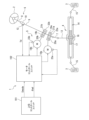
- FIG. 1 is a schematic diagram of an example of the configuration of an electric power steering system 1 to which a steering device according to an embodiment is applied.
- the host control unit 101 sets the control mode of the electric power steering system 1 .
- the host control unit 101 outputs a control mode signal Smode indicating the control mode.
- Smode indicating the control mode.
- the control mode of the electric power steering system 1 includes automatic driving control for autonomously driving the own vehicle based on the surrounding environment of the own vehicle and the driving state of the own vehicle, and automatic parking control for moving the own vehicle from the current position to the target parking position. , emergency avoidance control for avoiding obstacles in the direction of travel, and lane departure prevention control (lane keep control) for preventing the vehicle from departing from the driving lane.
- the control mode is automatic travel control, automatic parking control, emergency avoidance control, or lane departure prevention control
- the host control unit 101 calculates a target steering angle ⁇ ad, which is a target value of the steering angle of the steered wheels 3. and output.
- the host control unit 101 sets a target travel trajectory as a trajectory for the own vehicle to travel based on the surrounding environment of the own vehicle and the travel state of the own vehicle, and travels the own vehicle along the target travel trajectory.
- a steering angle for turning the wheel is calculated as a target steering angle ⁇ ad.
- the lane markings (lane markers) on the left and right of the lane in front of the vehicle are detected, and the target travel trajectory that passes through a predetermined position in the lane width direction with respect to the detected lane markings is calculated and calculated.
- a steering angle for causing the host vehicle to travel along the target travel trajectory is calculated as a target steering angle ⁇ ad.
- the host control unit 101 sets a target travel trajectory for moving the own vehicle to the target parking position based on the relative positional relationship between the current position of the own vehicle and the target parking position.
- a turning angle for driving the own vehicle along the road is calculated as a target turning angle ⁇ ad.
- the host control unit 101 calculates a turning angle for avoiding an obstacle in the traveling direction of the vehicle as a target turning angle ⁇ ad.
- the host control unit 101 calculates the turning angle for preventing the vehicle from departing from the traveling lane as the target turning angle ⁇ ad.
- Selection of the control mode in the host control unit 101 may be made by the driver using a selection switch (not shown) or the like connected to the host control unit 101 .
- a sensor is provided to detect the distance to an obstacle in front of the vehicle, and when an obstacle is detected within a predetermined distance in the vehicle's traveling direction during automatic cruise control, automatic cruise control is automatically switched to emergency avoidance control. may be selected according to the vehicle situation, such as changing to .
- automatic parking control is automatically started according to the vehicle situation. It may be automatically selected according to the situation. In this manner, the control mode selection method in the host control unit 101 can be changed as appropriate.
- the target steering angle ⁇ ad and the control mode signal Smode generated by the host control unit 101 are given to the motor control unit 102 via, for example, an in-vehicle network.
- Steering shaft 6 includes an input shaft 8 connected to steering wheel 2 and an output shaft 9 connected to intermediate shaft 7 .
- the input shaft 8 and the output shaft 9 are connected via a torsion bar 10 so as to be relatively rotatable.
- a torque sensor 12 is arranged near the torsion bar 10 .
- the torque sensor 12 detects the steering torque (actual steering torque) Td applied to the steering wheel 2 based on the amount of relative rotational displacement between the input shaft 8 and the output shaft 9 (that is, the amount of twist of the torsion bar). Detect as the current state, which is the current state.
- the actual steering torque Td is an example of the "current steering torque" described in the claims.
- the actual steering torque Td is obtained by, for example, detecting torque for leftward steering as a positive value and detecting torque for rightward steering as a negative value. It is assumed that the larger is, the larger the magnitude of the actual steering torque Td is.
- the steering mechanism 4 includes a rack and pinion mechanism including a pinion shaft 13 and a rack shaft 14 as a steering shaft.
- the steering wheel 3 is connected to each end of the rack shaft 14 via tie rods 15 and knuckle arms (not shown).
- the pinion shaft 13 is connected to the intermediate shaft 7 .
- the pinion shaft 13 rotates in conjunction with steering of the steering wheel 2 .
- a pinion 16 is connected to the tip of the pinion shaft 13 .
- the rack shaft 14 extends linearly along the lateral direction of the vehicle.
- a rack 17 that meshes with the pinion 16 is formed in the axially intermediate portion of the rack shaft 14 .
- the pinion 16 and rack 17 convert the rotational motion of the pinion shaft 13 into axial linear motion of the rack shaft 14 .
- the steerable wheels 3 can be steered by moving the rack shaft 14 in the axial direction. When the steering wheel 2 is steered (rotated), this rotation is transmitted to the pinion shaft 13 via the steering shaft 6 and intermediate shaft 7 . Rotation of the pinion shaft 13 is converted into axial movement of the rack shaft 14 by the pinion 16 and the rack 17 . As a result, the steerable wheels 3 are steered.
- the steering assist mechanism 5 amplifies the output torque of the first electric motor 18a and the second electric motor 18b for generating a steering assist force (assist torque) and the output torque of the first electric motor 18a and the second electric motor 18b. and a first reduction gear 19a and a second reduction gear 19b for transmitting to the steering mechanism 4.
- the first speed reducer 19a has a worm gear mechanism including a worm gear 20a and a worm wheel 21a that meshes with the worm gear 20a.
- the first speed reducer 19a is accommodated in a gear housing 22a as a transmission mechanism housing.
- the reduction ratio (gear ratio) of the first speed reducer 19a may be represented by N.
- the reduction ratio N is defined as the ratio ⁇ wg/ ⁇ ww of the angular velocity ⁇ wg of the worm gear 20a to the angular velocity ⁇ ww of the worm wheel 21a.
- the second reduction gear 19b has the same configuration as the first reduction gear 19a, and has a worm gear mechanism including a worm gear 20b and a worm wheel 21b meshing with the worm gear 20b in a gear housing 22b.
- the worm gear 20a of the first speed reducer 19a is rotationally driven by the first electric motor 18a. Further, the worm wheel 21a is connected to the output shaft 9 so as to rotate integrally therewith.
- the worm gear 20a is rotationally driven by the first electric motor 18a
- the worm wheel 21a is rotationally driven.
- the motor torque of the first electric motor 18a is applied to the steering shaft 6 to rotate the steering shaft 6 (output shaft 9).
- the worm gear 20b of the second speed reducer 19b is rotationally driven by the second electric motor 18b.
- the worm wheel 21b is connected to the output shaft 9 so as to be able to rotate integrally therewith.
- Rotation of the steering shaft 6 is transmitted to the pinion shaft 13 via the intermediate shaft 7 .
- the rotational motion of the pinion shaft 13 is converted into axial linear motion of the rack shaft 14 .
- the steered wheels 3 are steered by the motor torque of the first electric motor 18a and the second electric motor 18b.
- the steering wheel 2 also rotates as the steering shaft 6 rotates.
- the steering mechanism 4 for steering the steered wheels 3 is driven by the motor torque of the first electric motor 18a and the second electric motor 18b. becomes possible.
- the configuration of the first electric motor 18a and the second electric motor 18b shown in FIG. 1 is an example, and the present invention is not limited to such an example.
- the first electric motor 18a and the second electric motor 18b may be double winding motors in which two sets of windings are wound within the same motor housing to rotate a common rotor.
- a single speed reducer is arranged as the first speed reducer 19a and the second speed reducer 19b.
- FIG. 1 illustrates a column-assist type electric power steering system in which an electric motor is connected to a steering shaft
- the present invention is not limited to a column-assist type electric power steering system.
- the present invention can also be applied to an electric power steering system of a single pinion assist system or a dual pinion assist system in which an electric motor is connected to a pinion shaft, or a rack assist system in which an electric motor is arranged on a rack.
- a second pinion meshing with the rack 17 is added, one of the first electric motor 18a and the second electric motor 18b is connected to the pinion 16, and the other is connected to the second pinion.
- the first electric motor 18a and the second electric motor 18b are provided with rotation angle sensors 23a and 23b for detecting the rotation angles of the rotors of the first electric motor 18a and the second electric motor 18b, respectively.
- the actual steering torque Td detected by the torque sensor 12 and the output signals of the rotation angle sensors 23 a and 23 b are input to the motor control unit 102 .
- the motor control unit 102 controls the first electric motor 18a and the second electric motor 18b based on these input signals and information given from the host control unit 101 on the vehicle side.
- the motor control unit 102 calculates the current actual steering angle of the steerable wheels 3 based on the output signals of the rotation angle sensors 23a and 23b (hereinafter sometimes referred to as "actual steering angle"). is calculated as the current state, which is the current state of the host vehicle.
- the actual steering angle is an example of the "current steering angle” described in the claims.
- the motor control unit 102 also acquires the actual steering torque Td detected by the torque sensor 12 as the current state.
- the motor control unit 102 acquires the target steering angle ⁇ ad given from the host control unit 101 as a target state, which is a target value of the state of the vehicle. Also, a target steering torque, which is a target value of the steering torque, is set.
- the first electric motor 18a and the second electric motor 18b are mechanically connected via the first reduction gear 19a, the output shaft 9, and the second reduction gear 19b.
- the steering angles detected by the motor control unit 102 based on the output signal of the sensor 23b are substantially the same value. Therefore, either one of the rotation angle sensor 23a and the rotation angle sensor 23b may be omitted, and only the other may be provided.
- the motor control unit 102 outputs the total torque required to drive the steering mechanism for steering the steered wheels 3 based on the deviation between the current state and the target state to the first electric motor 18a and the second electric motor. 18b and generated.
- the motor control unit 102 sets the first steering command value i1 and the second steering command value i2 for generating torque to the first electric motor 18a and the second electric motor 18b, based on the deviation between the current state and the target state. It may be calculated by at least one of proportional control (P control), integral control (I control), and differential control (D control).
- the ratio of dividing the entire torque required for driving the steering mechanism to the first steering command value i1 and the second steering command value i2 is, for example, 50:50 (that is, the magnitude of the first steering command value i1 is equal to the magnitude of the second turning command value i2), or one of them may be made larger than the other.
- the motor control unit 102 drives the first electric motor 18a based on the first steering command value i1, and drives the second electric motor 18b based on the second steering command value i2.
- the first electric motor 18a and the second electric motor 18b may vibrate.
- the gains in the P control, I control, and D control are large, the first turning command value i1 and the second turning command value i2 increase when the target state or the current state changes. Vibration occurs in the transient response of the first steering command value i1 and the second steering command value i2 to the change in the state or the current state, and there is a possibility that the first electric motor 18a and the second electric motor 18b vibrate. .
- a small gain is set in order to suppress such vibration, the followability of the current state to the target state will be deteriorated.
- even when a large change occurs in the target state or the current state there is a possibility that the above-described vibration may occur regardless of the magnitude of the gain.
- the motor control unit 102 of the present invention provides a time difference between the first steering command value i1 and the second steering command value i2. That is, the motor control unit 102 generates a first steering command value i1 and a second steering command value i2 with a time difference therebetween. For example, one of the second steering command value i2 and the first steering command value i1 is output after being delayed from the other. In this way, if a time difference is provided between the first steering command value i1 and the second steering command value i2, if no time difference is provided (that is, if the time difference is not provided), It is possible to delay the generation of a part of the torque compared to the case where the entire torque driving the steering mechanism is generated at the same time.
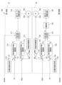
- FIG. 2 is a block diagram of an example of the functional configuration of the motor control unit 102 of the first embodiment.
- the rotation angle calculator 110 calculates the rotor rotation angle ⁇ ma of the first electric motor 18a based on the output signal of the rotation angle sensor 23a.
- a reduction ratio division unit 111 divides the rotor rotation angle ⁇ ma calculated by the rotation angle calculation unit 110 by the reduction ratio N, thereby converting the rotor rotation angle ⁇ ma into the rotation angle (actual steering angle) ⁇ a of the output shaft 9. do.
- the actual turning angle ⁇ a calculated by the reduction ratio dividing section 111 is given to the subtractor 112 .
- the third steering command value calculation unit 113 uses at least one of P control, I control, and D control with respect to the steering angle deviation ⁇ to obtain a third steering command value as a steering command value for driving the steering mechanism 4 . Calculate the value i3.
- the third steering command value calculation section 113 outputs the third steering command value i3 to the command value setting section 117 .
- the target state setting unit 114 sets the target steering torque Te.
- the target state setting section 114 may set the target steering torque Te according to the lateral acceleration generated in the host vehicle.
- the target state setting unit 114 may set the target steering torque Te to a value that increases as the lateral acceleration increases so that the steering torque required for steering increases as the lateral acceleration increases.
- the fourth steering command value calculation unit 116 calculates a fourth steering command value as a steering command value for driving the steering mechanism 4 by at least one of P control, I control, and D control for the steering torque deviation ⁇ T. Compute i4.
- the fourth steering command value calculation section 116 outputs the fourth steering command value i4 to the command value setting section 117 .
- the command value setting unit 117 sets a basic steering command value i0 based on the third steering command value i3 and the fourth steering command value i4.
- the basic steering command value i ⁇ b>0 is a steering command value that causes the electric motor to generate torque sufficient to cover the entire driving force applied to the steering mechanism 4 .
- the command value setting unit 117 may set either the third steering command value i3 or the fourth steering command value i4 to the basic steering command value i0 based on the control mode signal Smode.
- the control mode indicated by the control mode signal Smode is any one of automatic running control, automatic parking control, emergency avoidance control, and lane departure prevention control
- the third steering command value i3 is set to the basic steering command value i0.
- the fourth steering command value i4 may be set to the basic steering command value i0.
- the command value setting unit 117 may set the basic steering command value i0 based on the sum of the third steering command value i3 and the fourth steering command value i4. For example, the command value setting unit 117 may set the average value or weighted sum of the third steering command value i3 and the fourth steering command value i4 as the basic steering command value i0.
- the distribution unit 118 distributes the basic steering command value i0 set by the command value setting unit 117 to a first steering command value i1 and a second steering command value i2 with a time difference therebetween. It outputs to the motor drive circuit 119 and the second motor drive circuit 129 .
- the distribution unit 118 calculates the first steering command value i1 and the second steering command value i2 by distributing the basic steering command value i0 at a predetermined ratio (for example, 50:50). Then, either one of the first steering command value i1 and the second steering command value i2 is output after being delayed by a predetermined time difference D from the other.
- the first motor drive circuit 119 and the second motor drive circuit 129 respectively transfer the motor drive current based on the first steering command value i1 and the motor drive current based on the second steering command value i2 to the first electric motor 18a. It is supplied to the second electric motor 18b to drive the first electric motor 18a and the second electric motor 18b.
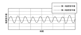
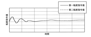
- FIG. 3A is a time chart of an example of the first steering command value i1 and the second steering command value i2 with no time difference
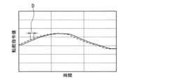
- FIG. FIG. 3C is an enlarged view of FIG. 3B
- FIG. A solid line indicates the first steering command value i1
- a dashed line indicates the second steering command value i2.
- the second steering command value i2 is a command value with the same waveform as the first steering command value i1.
- the waveforms completely overlap (match) because there is no time difference.
- the second steering command value i2 is delayed by the time difference D from the first steering command value i1 because a time difference is provided.
- the first steering command value i1 and the second steering command value i2 when no time difference is provided require time for the vibration to converge.
- the oscillation of the first steering command value i1 and the second steering command value i2 when the time difference is provided converges early.
- the time difference between the first steering command value i1 and the second steering command value i2 is such that the phase difference between the first steering command value i1 and the second steering command value i2 is 0 [deg]. It is preferably larger and less than 90 [deg].
- the reason is as follows. As described above, the convergence of the oscillations of the first steering command value i1 and the second steering command value i2 is caused by viscous resistance, and this viscous resistance is a differential term proportional to speed.
- phase of the signal advances by 90 [deg] due to the differentiation
- phase of one of the first steering command value i1 and the second steering command value i2 is advanced by 90 [deg] from the other phase
- the command value becomes a derivative term of the other command value. Therefore, when the phase difference between the first steering command value i1 and the second steering command value i2 becomes 90 [deg], all the components of the one command value with the phase leading by 90 [deg] Since it becomes a viscous resistance component, the effect of viscous resistance is maximized. Therefore, even if the time difference D is further increased, the effect of the viscous resistance does not increase, and the adverse effect of the control delay increases.
- the phase difference between the first steering command value i1 and the second steering command value i2 is greater than 0 [deg] and less than 90 [deg].
- the time difference D may be set to be less than 1/4 of the vibration period that is considered to occur in the transient response to the change in the first steering command value i1 and the second steering command value i2. For example, it may be set to less than 1/4 of the period of the highest frequency vibration that is considered to occur in transient response to changes in the first steering command value i1 and the second steering command value i2. For example, it is assumed that the highest frequency vibration that is considered to occur in the transient response to changes in the first steering command value i1 and the second steering command value i2 is any one of 20, 30, 50 and 100 [Hz]. In this case, the time difference D between the first steering command value i1 and the second steering command value i2 is any one of 12.5, 18.75, 31.25, and 62.5 [msec]. , may be set to a value that matches the vibration frequency.
- FIG. 4 is a flow chart of an example of the steering control method of the first embodiment.
- the rotation angle sensor 23a, the rotation angle calculator 110, and the reduction ratio divider 111 detect the actual steering angle ⁇ a.
- a torque sensor 12 detects an actual steering torque Td.
- the host control unit 101 sets the target steering angle ⁇ ad.
- the target state setting unit 114 also sets a target steering torque Te.
- step S3 the third steering command value calculator 113 calculates a third steering command value i3 based on the steering angle deviation ⁇ between the target steering angle ⁇ ad and the actual steering angle ⁇ a.
- step S4 the fourth steering command value calculator 116 calculates a fourth steering command value i4 based on the steering torque deviation ⁇ T between the target steering torque Te and the actual steering torque Td.
- step S5 the command value setting unit 117 sets a basic steering command value i0 based on the third steering command value i3 and the fourth steering command value i4.
- step S6 the distributing unit 118 distributes the basic steering command value i0 to the first steering command value i1 and the second steering command value i2 which are mutually provided with a time difference.
- step S7 the first motor drive circuit 119 and the second motor drive circuit 129 drive the first electric motor 18a and the second electric motor 18b based on the first steering command value i1 and the second steering command value i2, respectively. do.
- the motor control unit 102 of the first embodiment calculates a basic steering command value i0 that causes the electric motor to generate a torque that covers the entire driving force to be applied to the steering mechanism 4, and sets the basic steering command values i0 at a time difference from each other. was distributed to the first steering command value i1 and the second steering command value i2 provided with .
- the motor control unit 102 of the second embodiment has two redundant systems for calculating the steering command value, and each system independently calculates the first steering command value i1 and the second steering command value i2. , outputs a first steering command value i1 and a second steering command value i2 with a time difference to the first motor drive circuit 119 and the second motor drive circuit 129, respectively.
- FIG. 5 is a block diagram of an example of the functional configuration of the motor control unit 102 of the second embodiment.
- the first system S1 includes a rotation angle calculation unit 110, a reduction ratio division unit 111, a subtractor 112, a third steering command value calculation unit 113, a target state setting unit 114, a subtractor 115, and a fourth It includes a steering command value calculation unit 116, a command value setting unit 117, a first motor drive circuit 119, a first electric motor 18a, and a rotation angle sensor 23a.
- the second system S2 also has the same configuration as the first system S1, and includes a rotation angle calculator 120, a reduction ratio divider 121, a subtractor 122, a third steering command value calculator 123, and a target state.
- the rudder command value calculation unit 116 and the command value setting unit 117 are the rotation angle calculation unit 110, the reduction ratio division unit 111, the subtractor 112, and the third steering command value calculation unit 113 of the first embodiment, respectively. , the target state setting unit 114 , the subtractor 115 , the fourth steering command value calculation unit 116 , and the command value setting unit 117 .
- the command value setting unit 117 of the second embodiment outputs the first steering command value i1 instead of the basic steering command value i0.
- the command value setting unit 117 sets the first steering command value i1 based on the third steering command value i3 and the fourth steering command value i4. Therefore, the third steering command value calculation unit 113, the fourth steering command value calculation unit 116, and the command value setting unit 117 are configured to calculate the torque that covers the entire driving force applied to the steering mechanism 4.
- the first steering command value i1 corresponding to the torque generated by the electric motor 18a (for example, 50% of the total torque) is calculated.
- the steering command value calculation unit 126 and the command value setting unit 127 are the rotation angle calculation unit 110, the reduction ratio division unit 111, the subtractor 112, and the third steering command value calculation unit of the first system S1, respectively.
- target state setting unit 114 subtractor 115 , fourth turning command value computing unit 116 , and command value setting unit 117 .
- the rotation angle calculator 120 of the second system S2 calculates the rotor rotation angle ⁇ mb of the second electric motor 18b based on the output signal of the rotation angle sensor 23b.
- a reduction ratio dividing unit 121 divides the rotor rotation angle ⁇ mb by the reduction ratio N to convert the rotor rotation angle ⁇ mb into an actual steering angle ⁇ b.
- the command value setting unit 127 sets the second steering command value i2 based on the third steering command value i3 and the fourth steering command value i4.
- the third steering command value i3 and the fourth steering command value i4 used for setting the first steering command value i1 are obtained from the third steering command value calculation section 113 of the first system S1 and the fourth steering command value i4.
- the steering command value calculation unit 116 calculates.
- the third turning command value i3 and the fourth turning command value i4 used for setting the second turning command value i2 are obtained by the third turning command value calculating section 123 of the second system S2 and the fourth turning command value i4.
- the steering command value calculation unit 126 calculates.
- the signals of the target steering angle ⁇ ad and the actual steering torque Td are Since there is a time difference between the time input to the first system S1 and the time input to the second system S2, the first steering command value i1 and the second steering command value i2 with a time difference can be output. .
- the motor control unit 102 may be realized by two electronic control units comprising a control unit of the first system S1 and a control unit of the second system S2. Then, the control unit of the first system S1 receives the signals of the target turning angle ⁇ ad, the control mode signal Smode, and the actual steering torque Td from the host control unit 101 and the torque sensor 12, and the control unit of the second system S2 These signals may be received from the control unit of the first system S1. Accordingly, it is possible to provide a time difference between the time when the signals of the target steering angle ⁇ ad and the actual steering torque Td are input to the first system S1 and the time when they are input to the second system S2. In this case, the target steering angle ⁇ ad, the control mode signal Smode, and the actual steering torque Td, which are input to the control unit of the first system S1, are the same, and only the input time is different.
- FIG. 6 is a block diagram of an example of the functional configuration of the motor control unit 102 of the modified example of the second embodiment.
- a delay section after the command value setting section 117 of the first system S1 or the command value setting section 127 of the second system S2, the time difference between the first steering command value i1 and the second steering command value i2 is determined. may be provided.
- a delay section 130 is provided after the command value setting section 127 to delay the second steering command value i2.
- the delay time by the delay unit 130 may be a fixed value, or may be a variable value according to the vibration frequency of the second steering command value i2 (that is, the rate of change of the second steering command value i2). For example, the higher the frequency (the faster the rate of change), the shorter it may be set.
- Torque sensor 12, rotation angle sensor 23a, and motor control unit 102 detect the current state of the vehicle.
- the motor control unit 102 sets a target state, which is a target value of the state of the vehicle, and drives a steering mechanism 4 that steers the steered wheels 3 of the vehicle based on the deviation between the current state and the target state.
- a first steering command value and a second steering command value having a time difference are calculated as steering command values for the first electric motor 18a that drives the steering mechanism 4.
- the second electric motor 18b that drives the steering mechanism 4 is driven based on the second steering command value.
- the vibration generated by the transient response of the first steering command value and the second steering command value can be attenuated, so that the vibration generated in the first electric motor 18a and the second electric motor 18b can be suppressed. can.
- the current state may be the current steering angle of the host vehicle
- the target state may be the target steering angle set as the target value of the steering angle of the host vehicle.
- the first electric motor 18a and the second electric motor 18b can be driven so that the actual steering angle of the host vehicle becomes the target steering angle.
- a target travel trajectory may be set as the trajectory on which the host vehicle travels, and a steering angle for traveling along the target travel trajectory may be calculated as the target steering angle.
- the first electric motor 18a and the second electric motor 18b can be driven so that the own vehicle travels along the target travel trajectory.
- a target steering angle may be calculated as a steering angle for avoiding obstacles in the traveling direction of the vehicle or as a steering angle for preventing the vehicle from deviating from the travel lane. .
- the first electric motor 18a and the second electric motor 18b can be driven so as to avoid obstacles in the traveling direction of the vehicle or to prevent the vehicle from deviating from the lane.
- the current steering angle, which is the current steering angle of the host vehicle, and the current steering torque, which is the current steering torque of the host vehicle may be detected as the current state.
- the motor control unit 102 sets a target steering angle, which is a target value of the steering angle of the host vehicle, and a target steering torque, which is a target value of the steering torque of the host vehicle, as target states.
- the first steering command value and the second steering command value may be calculated based on either the deviation from the steering angle or the deviation between the current steering torque and the target steering torque.
- the first electric motor 18a and the second electric motor 18b can be driven.
- the current steering angle, which is the current steering angle of the host vehicle, and the current steering torque, which is the current steering torque of the host vehicle, may be detected as the current state.
- a target steering angle, which is the target value of the steering angle of the host vehicle, and a target steering torque, which is the target value of the steering torque of the host vehicle, are set as target states, and the distance between the current steering angle and the target steering angle is calculated.
- a third steering command value is calculated based on the deviation
- a fourth steering command value is calculated based on the deviation between the current steering torque and the target steering torque
- the first steering command value and the second steering command value may be calculated based on the sum of the command values.
- the first electric motor 18a and the second electric motor 18b can be driven so that the deviation between the current steering angle and the target steering angle and the deviation between the current steering torque and the target steering torque are reduced.
- the time difference between the first steer command value and the second steer command value is less than 1/4 of the period of the highest frequency vibration that is considered to occur in the transient response to changes in the steer command value. can be set to Thereby, it is possible to provide a time difference suitable for the vibration frequency of the first steering command value and the second steering command value.
- the motor control unit 102 sets a basic steering command value based on the deviation between the current state and the target state, and divides the basic steering command value into the first steering command value and the second steering command value at a predetermined ratio. It may be distributed to two steering command values. As a result, the first electric motor 18a and the second electric motor 18b can generate torque sufficient to cover the entire driving force applied to the steering mechanism 4.
- the motor control unit 102 calculates the first steering command value based on the deviation between the current state and the target state, and calculates the difference between the current state and the target state separately from the calculation of the first steering command value.
- the second steering command value may be calculated based on the deviation between the two.
- SYMBOLS 1 Electric power steering system, 2... Steering wheel, 3... Steering wheel, 4... Steering mechanism, 5... Steering assistance mechanism, 6... Steering shaft, 7... Intermediate shaft, 8... Input shaft, 9... Output shaft, DESCRIPTION OF SYMBOLS 10... Torsion bar 12... Torque sensor 13... Pinion shaft 14... Rack shaft 15... Tie rod 16... Pinion 17... Rack 18a... First electric motor 18b... Second electric motor 19a...
Landscapes
- Engineering & Computer Science (AREA)
- Chemical & Material Sciences (AREA)
- Combustion & Propulsion (AREA)
- Transportation (AREA)
- Mechanical Engineering (AREA)
- Physics & Mathematics (AREA)
- Mathematical Physics (AREA)
- Steering Control In Accordance With Driving Conditions (AREA)
- Power Steering Mechanism (AREA)
Priority Applications (4)
| Application Number | Priority Date | Filing Date | Title |
|---|---|---|---|
| CN202280068697.9A CN118103278B (zh) | 2021-10-12 | 2022-07-22 | 操舵控制方法及操舵装置 |
| US18/691,478 US12139197B1 (en) | 2021-10-12 | 2022-07-22 | Steering control method and steering device |
| EP22879592.8A EP4417495A4 (en) | 2021-10-12 | 2022-07-22 | STEERING CONTROL METHOD AND STEERING DEVICE |
| JP2023554269A JP7565456B2 (ja) | 2021-10-12 | 2022-07-22 | 操舵制御方法及び操舵装置 |
Applications Claiming Priority (2)
| Application Number | Priority Date | Filing Date | Title |
|---|---|---|---|
| JP2021-167227 | 2021-10-12 | ||
| JP2021167227 | 2021-10-12 |
Publications (1)
| Publication Number | Publication Date |
|---|---|
| WO2023062907A1 true WO2023062907A1 (ja) | 2023-04-20 |
Family
ID=85988248
Family Applications (1)
| Application Number | Title | Priority Date | Filing Date |
|---|---|---|---|
| PCT/JP2022/028497 Ceased WO2023062907A1 (ja) | 2021-10-12 | 2022-07-22 | 操舵制御方法及び操舵装置 |
Country Status (5)
| Country | Link |
|---|---|
| US (1) | US12139197B1 (https=) |
| EP (1) | EP4417495A4 (https=) |
| JP (1) | JP7565456B2 (https=) |
| CN (1) | CN118103278B (https=) |
| WO (1) | WO2023062907A1 (https=) |
Families Citing this family (1)
| Publication number | Priority date | Publication date | Assignee | Title |
|---|---|---|---|---|
| WO2026083481A1 (ja) * | 2024-10-15 | 2026-04-23 | 株式会社ジェイテクト | ステアリングシステム |
Citations (10)
| Publication number | Priority date | Publication date | Assignee | Title |
|---|---|---|---|---|
| JP2015039256A (ja) * | 2013-03-15 | 2015-02-26 | 日本精工株式会社 | モータ制御装置、これを使用した電動パワーステアリング装置及び車両 |
| JP2015163498A (ja) * | 2013-05-15 | 2015-09-10 | 株式会社ジェイテクト | 電動パワーステアリング装置 |
| WO2015141795A1 (ja) * | 2014-03-20 | 2015-09-24 | 日本精工株式会社 | 電動機制御装置、電動パワーステアリング装置および車両 |
| JP2017177943A (ja) | 2016-03-29 | 2017-10-05 | 株式会社Subaru | 自動操舵装置 |
| WO2018051838A1 (ja) * | 2016-09-16 | 2018-03-22 | 日立オートモティブシステムズ株式会社 | 車両制御装置、車両制御方法および電動パワーステアリング装置 |
| WO2018088465A1 (ja) * | 2016-11-11 | 2018-05-17 | 株式会社デンソー | 回転電機制御装置、および、これを用いた電動パワーステアリング装置 |
| JP2018130007A (ja) * | 2016-11-11 | 2018-08-16 | 株式会社デンソー | 回転電機制御装置、および、これを用いた電動パワーステアリング装置 |
| WO2020105620A1 (ja) * | 2018-11-20 | 2020-05-28 | 株式会社ジェイテクト | 操舵装置および操舵装置におけるモータ制御方法 |
| JP2020092583A (ja) * | 2018-12-07 | 2020-06-11 | 株式会社デンソー | ステアリングシステム |
| WO2020230307A1 (ja) * | 2019-05-15 | 2020-11-19 | 日産自動車株式会社 | 操舵制御方法及び操舵制御装置 |
Family Cites Families (7)
| Publication number | Priority date | Publication date | Assignee | Title |
|---|---|---|---|---|
| JP3858485B2 (ja) * | 1998-11-26 | 2006-12-13 | マツダ株式会社 | 車両の制御装置 |
| DE102005052034A1 (de) * | 2005-10-31 | 2007-05-03 | Robert Bosch Gmbh | LKS-System mit modifizierter Regelcharakteristik bei Kurvenfahrt |
| JP5418056B2 (ja) * | 2009-08-14 | 2014-02-19 | 日産自動車株式会社 | 操舵制御装置 |
| US9592850B1 (en) * | 2016-04-22 | 2017-03-14 | Denso Corporation | Steering control apparatus |
| CN110382332B (zh) | 2017-03-09 | 2021-12-24 | 日立安斯泰莫株式会社 | 动力转向装置 |
| JP6958183B2 (ja) | 2017-09-27 | 2021-11-02 | 株式会社ジェイテクト | 車両用制御装置 |
| JP7170971B2 (ja) * | 2019-04-18 | 2022-11-15 | 日本精工株式会社 | 車両用操向システムの制御装置 |
-
2022
- 2022-07-22 US US18/691,478 patent/US12139197B1/en active Active
- 2022-07-22 EP EP22879592.8A patent/EP4417495A4/en active Pending
- 2022-07-22 CN CN202280068697.9A patent/CN118103278B/zh active Active
- 2022-07-22 JP JP2023554269A patent/JP7565456B2/ja active Active
- 2022-07-22 WO PCT/JP2022/028497 patent/WO2023062907A1/ja not_active Ceased
Patent Citations (10)
| Publication number | Priority date | Publication date | Assignee | Title |
|---|---|---|---|---|
| JP2015039256A (ja) * | 2013-03-15 | 2015-02-26 | 日本精工株式会社 | モータ制御装置、これを使用した電動パワーステアリング装置及び車両 |
| JP2015163498A (ja) * | 2013-05-15 | 2015-09-10 | 株式会社ジェイテクト | 電動パワーステアリング装置 |
| WO2015141795A1 (ja) * | 2014-03-20 | 2015-09-24 | 日本精工株式会社 | 電動機制御装置、電動パワーステアリング装置および車両 |
| JP2017177943A (ja) | 2016-03-29 | 2017-10-05 | 株式会社Subaru | 自動操舵装置 |
| WO2018051838A1 (ja) * | 2016-09-16 | 2018-03-22 | 日立オートモティブシステムズ株式会社 | 車両制御装置、車両制御方法および電動パワーステアリング装置 |
| WO2018088465A1 (ja) * | 2016-11-11 | 2018-05-17 | 株式会社デンソー | 回転電機制御装置、および、これを用いた電動パワーステアリング装置 |
| JP2018130007A (ja) * | 2016-11-11 | 2018-08-16 | 株式会社デンソー | 回転電機制御装置、および、これを用いた電動パワーステアリング装置 |
| WO2020105620A1 (ja) * | 2018-11-20 | 2020-05-28 | 株式会社ジェイテクト | 操舵装置および操舵装置におけるモータ制御方法 |
| JP2020092583A (ja) * | 2018-12-07 | 2020-06-11 | 株式会社デンソー | ステアリングシステム |
| WO2020230307A1 (ja) * | 2019-05-15 | 2020-11-19 | 日産自動車株式会社 | 操舵制御方法及び操舵制御装置 |
Non-Patent Citations (1)
| Title |
|---|
| See also references of EP4417495A4 |
Also Published As
| Publication number | Publication date |
|---|---|
| JP7565456B2 (ja) | 2024-10-10 |
| EP4417495A4 (en) | 2025-03-05 |
| US12139197B1 (en) | 2024-11-12 |
| US20240375713A1 (en) | 2024-11-14 |
| CN118103278B (zh) | 2025-04-01 |
| JPWO2023062907A1 (https=) | 2023-04-20 |
| EP4417495A1 (en) | 2024-08-21 |
| CN118103278A (zh) | 2024-05-28 |
Similar Documents
| Publication | Publication Date | Title |
|---|---|---|
| CN100562454C (zh) | 电动转向设备及其控制方法 | |
| EP3632774B1 (en) | Controller for steering system and method for controlling steering system | |
| JP5126357B2 (ja) | 車両の操舵装置 | |
| JP5338983B2 (ja) | 車両走行制御装置 | |
| JP5971512B2 (ja) | 車両用操舵装置 | |
| JP6299164B2 (ja) | 操舵制御装置 | |
| JP7136025B2 (ja) | ステアリング制御装置 | |
| US11091195B2 (en) | Motor control device and motor control method | |
| US11383760B2 (en) | Steering system | |
| WO2020105620A1 (ja) | 操舵装置および操舵装置におけるモータ制御方法 | |
| JP2020168918A (ja) | 操舵装置 | |
| JP2020069862A (ja) | 操舵制御装置 | |
| JP2018103713A (ja) | 車両走行制御装置及び自動運転制御方法 | |
| JP2020069861A (ja) | 操舵制御装置 | |
| JP2019131015A (ja) | 操舵制御装置 | |
| JP2020069863A (ja) | 操舵制御装置 | |
| CN118284551A (zh) | 马达控制装置 | |
| US20220017143A1 (en) | Steering device | |
| JP7565456B2 (ja) | 操舵制御方法及び操舵装置 | |
| JP5831406B2 (ja) | 操舵装置及び操舵制御装置 | |
| US20190039650A1 (en) | Vehicle steering control device | |
| JP2019018772A (ja) | 操舵制御装置、電動パワーステアリング装置 | |
| JP2014136479A (ja) | 電動パワーステアリング装置 | |
| JP2016165953A (ja) | 電動パワーステアリング装置 | |
| JP2015186942A (ja) | 電動パワーステアリング装置、プログラム |
Legal Events
| Date | Code | Title | Description |
|---|---|---|---|
| 121 | Ep: the epo has been informed by wipo that ep was designated in this application |
Ref document number: 22879592 Country of ref document: EP Kind code of ref document: A1 |
|
| WWE | Wipo information: entry into national phase |
Ref document number: 2023554269 Country of ref document: JP |
|
| WWE | Wipo information: entry into national phase |
Ref document number: 18691478 Country of ref document: US |
|
| WWE | Wipo information: entry into national phase |
Ref document number: 202280068697.9 Country of ref document: CN |
|
| WWE | Wipo information: entry into national phase |
Ref document number: 2022879592 Country of ref document: EP |
|
| NENP | Non-entry into the national phase |
Ref country code: DE |
|
| ENP | Entry into the national phase |
Ref document number: 2022879592 Country of ref document: EP Effective date: 20240513 |
|
| WWG | Wipo information: grant in national office |
Ref document number: 202280068697.9 Country of ref document: CN |