WO2020105620A1 - 操舵装置および操舵装置におけるモータ制御方法 - Google Patents
操舵装置および操舵装置におけるモータ制御方法Info
- Publication number
- WO2020105620A1 WO2020105620A1 PCT/JP2019/045224 JP2019045224W WO2020105620A1 WO 2020105620 A1 WO2020105620 A1 WO 2020105620A1 JP 2019045224 W JP2019045224 W JP 2019045224W WO 2020105620 A1 WO2020105620 A1 WO 2020105620A1
- Authority
- WO
- WIPO (PCT)
- Prior art keywords
- control
- gain
- steering angle
- feedback
- steering
- Prior art date
Links
Images

Classifications
-
- B—PERFORMING OPERATIONS; TRANSPORTING
- B62—LAND VEHICLES FOR TRAVELLING OTHERWISE THAN ON RAILS
- B62D—MOTOR VEHICLES; TRAILERS
- B62D5/00—Power-assisted or power-driven steering
- B62D5/04—Power-assisted or power-driven steering electrical, e.g. using an electric servo-motor connected to, or forming part of, the steering gear
- B62D5/0457—Power-assisted or power-driven steering electrical, e.g. using an electric servo-motor connected to, or forming part of, the steering gear characterised by control features of the drive means as such
- B62D5/046—Controlling the motor
- B62D5/0463—Controlling the motor calculating assisting torque from the motor based on driver input
-
- B—PERFORMING OPERATIONS; TRANSPORTING
- B62—LAND VEHICLES FOR TRAVELLING OTHERWISE THAN ON RAILS
- B62D—MOTOR VEHICLES; TRAILERS
- B62D15/00—Steering not otherwise provided for
- B62D15/02—Steering position indicators ; Steering position determination; Steering aids
- B62D15/025—Active steering aids, e.g. helping the driver by actively influencing the steering system after environment evaluation
- B62D15/0265—Automatic obstacle avoidance by steering
-
- B—PERFORMING OPERATIONS; TRANSPORTING
- B62—LAND VEHICLES FOR TRAVELLING OTHERWISE THAN ON RAILS
- B62D—MOTOR VEHICLES; TRAILERS
- B62D15/00—Steering not otherwise provided for
- B62D15/02—Steering position indicators ; Steering position determination; Steering aids
- B62D15/025—Active steering aids, e.g. helping the driver by actively influencing the steering system after environment evaluation
-
- B—PERFORMING OPERATIONS; TRANSPORTING
- B62—LAND VEHICLES FOR TRAVELLING OTHERWISE THAN ON RAILS
- B62D—MOTOR VEHICLES; TRAILERS
- B62D15/00—Steering not otherwise provided for
- B62D15/02—Steering position indicators ; Steering position determination; Steering aids
- B62D15/027—Parking aids, e.g. instruction means
- B62D15/0285—Parking performed automatically
-
- B—PERFORMING OPERATIONS; TRANSPORTING
- B62—LAND VEHICLES FOR TRAVELLING OTHERWISE THAN ON RAILS
- B62D—MOTOR VEHICLES; TRAILERS
- B62D6/00—Arrangements for automatically controlling steering depending on driving conditions sensed and responded to, e.g. control circuits
- B62D6/008—Control of feed-back to the steering input member, e.g. simulating road feel in steer-by-wire applications
-
- B—PERFORMING OPERATIONS; TRANSPORTING
- B62—LAND VEHICLES FOR TRAVELLING OTHERWISE THAN ON RAILS
- B62D—MOTOR VEHICLES; TRAILERS
- B62D6/00—Arrangements for automatically controlling steering depending on driving conditions sensed and responded to, e.g. control circuits
- B62D6/002—Arrangements for automatically controlling steering depending on driving conditions sensed and responded to, e.g. control circuits computing target steering angles for front or rear wheels
Definitions
- One aspect of the present invention relates to a steering device and a motor control method in the steering device.
- the target steering angle (target steering angle or target steering angle) is calculated so that the vehicle automatically travels along the target route set in the travel route, and the actual steering angle is matched with the target steering angle.
- automatic traveling control that feedback-controls a steering actuator (see, for example, Patent Document 1 below).
- the automatic steering that calculates the target steering angle to move the vehicle automatically from the current position to the parking position specified by the driver and feedback-controls the steering actuator so that the actual steering angle matches the target steering angle. Control is known (see, for example, Patent Document 2 below).
- An object of the present invention is to provide a steering device and a motor control method in the steering device that can perform automatic traveling control and automatic parking control, and can suppress the occurrence of vibration during automatic parking control.
- a steering apparatus includes an electric motor that can steer steered wheels connected to a steering wheel, and a control unit that controls the electric motor to change a steering angle of the steered wheels.
- Automatic traveling control for performing feedback control so that the actual steering angle matches the first target steering angle calculated so that the vehicle travels along the target route set in the travel route, and the vehicle from the current position
- An angle feedback control unit capable of executing an automatic parking control for performing feedback control so that the actual steering angle matches the second target steering angle calculated to move to the parking position, and a feedback gain in the automatic parking control.
- a gain setting unit that sets a value smaller than a feedback gain in the automatic traveling control.
- the feedback control is proportional-integral-derivative control
- the feedback gain includes a differential gain of the proportional-integral-derivative control.
- the feedback gain further includes a proportional gain of the proportional-plus-integral-derivative control.
- the feedback gain further includes an integral gain of the proportional-plus-integral-derivative control.
- the angle feedback control unit when detecting a risk of colliding with an obstacle in the vehicle traveling direction, is calculated to move the vehicle in a direction in which the obstacle does not exist. 3 It is also possible to execute an emergency avoidance assistance control that performs feedback control so that the actual steering angle matches the target steering angle, and the gain setting unit uses the feedback gain in the emergency avoidance assistance control as feedback in the automatic traveling control. Set to a value larger than the gain.
- a motor control method for a steering device is a motor control method for a steering device that includes an electric motor that can steer steered wheels connected to a steering wheel, and that can execute automatic traveling control and automatic parking control.
- the automatic travel control is a step of calculating a first target steering angle so that the vehicle travels along a target route set in the travel path, and feedback so that the actual steering angle matches the first target steering angle.
- a step of performing control wherein the automatic parking control calculates a second target steering angle so that the vehicle moves from a current position to a parking position, and a value smaller than a feedback gain in the automatic travel control. Feedback control is performed so that the actual steering angle matches the second target steering angle using the feedback gain set to.
- FIG. 1 is a schematic diagram showing a schematic configuration of an electric power steering system to which a steering device according to an embodiment of the present invention is applied.
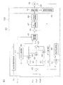
- FIG. 2 is a block diagram for explaining the electrical configuration of the motor control ECU.
- FIG. 1 is a schematic diagram showing a schematic configuration of an electric power steering system to which a steering device according to an embodiment of the present invention is applied.
- the electric power steering system 1 includes a steering wheel 2 as a steering member for steering a vehicle, a steering mechanism 4 that steers the steered wheels 3 in association with the rotation of the steering wheel 2, and a steering of a driver. And a steering assist mechanism 5 for assisting the vehicle.
- the steering wheel 2 and the steering mechanism 4 are mechanically connected via a steering shaft 6 and an intermediate shaft 7. Thereby, the steering wheel 2 and the steered wheels 3 are mechanically connected.
- the steering shaft 6 includes an input shaft 8 connected to the steering wheel 2 and an output shaft 9 connected to the intermediate shaft 7.
- the input shaft 8 and the output shaft 9 are rotatably connected to each other via a torsion bar 10.
- a torque sensor 12 is arranged near the torsion bar 10.
- the torque sensor 12 detects the steering torque T d applied to the steering wheel 2 based on the relative rotational displacement amount of the input shaft 8 and the output shaft 9.
- the torque for steering to the left is detected as a positive value and the torque for steering to the right is a negative value. Is detected, and the larger the absolute value, the larger the steering torque T d .
- the steering mechanism 4 comprises a rack and pinion mechanism including a pinion shaft 13 and a rack shaft 14 as a steering shaft.
- the steered wheels 3 are connected to each end of the rack shaft 14 via a tie rod 15 and a knuckle arm (not shown).
- the pinion shaft 13 is connected to the intermediate shaft 7.
- the pinion shaft 13 is adapted to rotate in association with steering of the steering wheel 2.
- a pinion 16 is connected to the tip of the pinion shaft 13.
- the rack shaft 14 extends linearly in the left-right direction of the vehicle.
- a rack 17 that meshes with the pinion 16 is formed at an axially intermediate portion of the rack shaft 14.
- the pinion 16 and the rack 17 convert the rotation of the pinion shaft 13 into the axial movement of the rack shaft 14.
- the steered wheels 3 can be steered by moving the rack shaft 14 in the axial direction.
- the steering assist mechanism 5 includes an electric motor 18 for generating a steering assist force (assist torque), and a speed reducer 19 for amplifying the output torque of the electric motor 18 and transmitting the amplified output torque to the steering mechanism 4.
- the speed reducer 19 includes a worm gear mechanism including a worm gear 20 and a worm wheel 21 that meshes with the worm gear 20.
- the speed reducer 19 is housed in a gear housing 22 as a transmission mechanism housing.
- the reduction ratio (gear ratio) of the speed reducer 19 may be represented by N.
- the reduction ratio N is defined as the ratio ⁇ wg / ⁇ ww of the angular velocity ⁇ wg of the worm gear 20 to the angular velocity ⁇ ww of the worm wheel 21.
- the worm gear 20 is rotationally driven by the electric motor 18. Further, the worm wheel 21 is integrally rotatably connected to the output shaft 9.
- automatic traveling control means that the actual steering angle matches the target steering angle (hereinafter, referred to as “first target steering angle”) calculated so that the vehicle travels along the target route set in the travel route.
- the feedback control is performed so that the feedback control is performed.
- the automatic travel control for example, in order to maintain traveling at a predetermined position in the lane width direction within the lane, by continuously setting the target travel position as the predetermined position in the lane width direction within the lane, the target route is set.
- the automatic traveling control sets a traveling route from the current position to the destination, performs automatic feedback control to perform the feedback control, and sets a traveling route that overtakes a preceding vehicle whose traveling speed is slower than the own vehicle. , Including automatic overtaking control for performing the above feedback control.
- the automatic travel control sets a target travel route on the travel route (road) and sets the actual steering angle to the target steering angle calculated so that the vehicle travels along the target route. Includes all controls that perform feedback control so that they match.
- the automatic parking control performs feedback control so that the actual steering angle matches the target steering angle (hereinafter, referred to as “second target steering angle”) calculated so that the vehicle moves from the current position to the parking position.
- the target steering angle is the target rotation angle with respect to the output shaft 9.
- the electric power steering system 1 further includes a motor control ECU (control unit) 102.
- the steering torque T d detected by the torque sensor 12 and the output signal of the rotation angle sensor 23 are input to the motor control ECU 102.
- the motor control ECU 102 controls the electric motor 18 based on these input signals and information provided from the vehicle-side host ECU 101.
- the host ECU 101 has a function of generating a first target steering angle ⁇ ad1 for automatically traveling the vehicle along a target route during the lane keeping control and giving the first target steering angle ⁇ ad1 to the motor control ECU 102 and a predetermined parking position for the vehicle during the automatic parking control. It is provided with a function of generating a second target steering angle ⁇ ad2 for moving to the motor control ECU 102. Since the process of generating the first target steering angle ⁇ ad1 and the second target steering angle ⁇ ad2 is well known, detailed description thereof will be omitted here.
- the host ECU 101 has a function of giving a control mode signal S mode indicating a control mode set by the driver to the motor control ECU 102.
- the control modes include a normal control mode performed during normal traveling, a lane keep control mode for performing lane keep control, and an automatic parking control mode for performing automatic parking control.
- the first target steering angle ⁇ ad1 and the second target steering angle ⁇ ad2 and the control mode signal S mode generated by the host ECU 101 are provided to the motor control ECU 102 via, for example, an in-vehicle network.
- FIG. 2 is a block diagram for explaining the electrical configuration of the motor control ECU 102.
- the motor control ECU 102 is a microcomputer 40, a drive circuit (inverter circuit) 31 that is controlled by the microcomputer 40 and supplies electric power to the electric motor 18, and a current flowing through the electric motor 18 (hereinafter referred to as “motor current I”). ) Is detected.
- the microcomputer 40 includes a CPU and a memory (ROM, RAM, non-volatile memory, etc.), and functions as a plurality of functional processing units by executing a predetermined program.
- the plurality of function processing units include a current command value setting unit 41, an angle deviation calculation unit 43, a PID (proportional integral derivative) control unit 44 (angle feedback control unit), a command value switching unit 45, and a current deviation.
- the calculation unit 46, a PI (proportional integration) control unit 47, a PWM control unit 48, a rotation angle calculation unit 49, a reduction ratio division unit 50, and a gain setting unit 51 are included.
- the current command value setting unit 41 calculates the current command value I as for the electric motor 18 in the normal control mode based on the steering torque T d .
- the current command value I as takes a positive value with respect to the positive value of the steering torque T d , and causes the electric motor 18 to generate a steering assist force for leftward steering. Further, the current command value I as takes a negative value with respect to the negative value of the steering torque T d , and causes the electric motor 18 to generate a steering assist force for steering to the right. Then, the current command value I as is set such that the larger the absolute value of the steering torque T d , the larger the absolute value thereof.
- the current command value I as calculated by the current command value setting unit 41 is input to the command value switching unit 45.
- the rotation angle calculation unit 49 calculates the rotor rotation angle ⁇ m of the electric motor 18 based on the output signal of the rotation angle sensor 23.
- the reduction gear ratio division unit 50 divides the rotor rotation angle ⁇ m calculated by the rotation angle calculation unit 49 by the reduction gear ratio N so that the rotor rotation angle ⁇ m becomes the rotation angle (actual steering angle) ⁇ of the output shaft 9. Convert.
- the actual steering angle ⁇ calculated by the reduction ratio division unit 50 is given to the angle deviation calculation unit 43.
- the PID control unit 44 calculates the current command value I ad by performing PID calculation on the angle deviation ⁇ calculated by the angle deviation calculation unit 43.
- the PID control unit 44 includes a proportional processing unit 61, an integral processing unit 62, a differential processing unit 63, a proportional gain multiplication unit 64, an integral gain multiplication unit 65, a differential gain multiplication unit 66, and an addition unit 67. There is.
- the proportional gain multiplication unit 64 multiplies the proportional processing of the angular deviation ⁇ by the proportional processing unit 61 by the proportional gain K P given from the gain setting unit 51.
- the integral gain multiplying unit 65 multiplies the integral processing of the angular deviation ⁇ by the integral processing unit 62 by the integral gain K I given from the gain setting unit 51.
- the differential gain multiplying unit 66 multiplies the differential processing unit 63 by differentiating the angular deviation ⁇ by the differential gain K D given from the gain setting unit 51. Details of the operation of the gain setting unit 51 will be described later.
- the addition unit 67 adds the multiplication results of the proportional gain multiplication unit 64, the integral gain multiplication unit 65, and the differential gain multiplication unit 66 to give a current command to the electric motor 18 in the lane keep control mode or the automatic parking control mode. Calculate the value I ad .
- the current command value I ad calculated by the PID control unit 44 is input to the command value switching unit 45.
- the command value switching unit 45 selects and outputs the current command value I as when the control mode signal S mode is a signal representing the normal control mode, and when the control mode signal S mode is a signal representing another lane keep control mode, or automatically. When it is a signal indicating the parking control mode, the current command value Iad is selected and output.
- the output of the command value switching unit 45 is given to the current deviation calculation unit 46.
- the PI control unit 47 guides the motor current I flowing through the electric motor 18 to the current command value I as or I ad by performing PI calculation (proportional integral calculation) on the current deviation ⁇ I calculated by the current deviation calculation unit 46.
- the PWM control unit 48 generates a PWM control signal having a duty ratio corresponding to the drive command value and supplies it to the drive circuit 31. As a result, electric power corresponding to the drive command value is supplied to the electric motor 18.
- the current command value I as set by the current command value setting unit 41 is output from the command value switching unit 45. Therefore, the assist torque corresponding to the steering torque T d is generated from the electric motor 18.
- the control mode is set to the lane keep control mode
- the first target steering angle ⁇ ad1 is given to the motor control ECU 102 from the host ECU 101.
- the drive circuit 31 is drive-controlled so that the motor current I matches the current command value I ad .
- the electric motor 18 is controlled so that the actual steering angle ⁇ matches the first target steering angle ⁇ ad1 .
- the gain setting unit 51 sets the proportional gain K P , the integral gain K I, and the differential gain K D according to the control mode signal S mode given from the host ECU 101.
- the proportional gain K P , the integral gain K I and the derivative gain K D set when the control mode is the lane keep control mode are respectively the first proportional gain K P1 , the first integral gain K I1 and the first derivative gain K. Let it be D1 .
- the proportional gain K P , the integral gain K I, and the derivative gain K D set when the control mode is the automatic parking control mode are the second proportional gain K P2 , the second integral gain K I2, and the second integral gain K I2 , respectively.
- the second differential gain K D2 is the second differential gain K D2 .
- the second proportional gain K P2 , the second integral gain K I2, and the second derivative gain K D2 are smaller than the first proportional gain K P1 , the first integral gain K I1, and the first derivative gain K D1 , respectively. It is set. The reason for this will be described below. Since the vehicle speed during the lane keep control is usually higher than the vehicle speed during the automatic parking control, higher responsiveness is required for the lane keep control than for the automatic parking control. Therefore, the first proportional gain K P1 , the first integral gain K I1 and the first derivative gain K D1 during the lane keeping control are set to relatively large values.
- the feedback gains K P1 , K I1 , and K D1 of the lane keeping control are set to relatively high values, and then the feedback gains K P2 , K I2 , and K D2 of the automatic parking control are set to the feedback of the lane keeping control. If the gains K P1 , K I1 , and K D1 are set to the same values, the response becomes excessively high with respect to the vehicle speed during automatic parking control, so that vibration occurs in the electric motor 18 during automatic parking control, and the driver It turned out to be a strange feeling.
- the second proportional gain K P2 , the second integral gain K I2, and the second differential gain K D2 are respectively set to the first proportional gain.
- the gain K P1 , the first integral gain K I1, and the first differential gain K D1 are set to values smaller than the values. Thereby, the vibration of the electric motor 18 that occurs during the automatic parking control can be suppressed.
- the responsiveness during the automatic parking control is increased. Although it decreases, the automatic parking control does not require high responsiveness as compared with the lane keep control, so that the automatic parking control is not hindered.
- the second proportional gain K P2 , the second integral gain K I2, and the second differential gain K D2 only the second differential gain K D2 is set to a value smaller than the first differential gain K D1. Good.
- the second proportional gain K P2 , the second integral gain K I2, and the second differential gain K D2 are respectively calculated as It may be set to a value smaller than the first derivative gain K D1 and the first proportional gain K P1 .
- the second differential gain K D2 is set to a value smaller than the first differential gain K D1 to perform automatic parking control.
- the second differential gain K D2 and the second proportional gain K P2 ⁇ are set to values smaller than the first differential gain K D1 and the first proportional gain K P1 , respectively. It is preferable to set. This makes it possible to more effectively suppress the vibration of the electric motor 18 during the automatic parking control, as compared with the case where only the second differential gain K D2 is set to a value smaller than the first differential gain K D1 .
- the second proportional gain K P2 , the second integral gain K I2, and the second derivative gain K D2 are set to values smaller than the first proportional gain K P1 , the first integral gain K I1, and the first derivative gain K D1 , respectively. It is preferable to set. Thereby, the stability of the PID control system can be improved. Therefore, all of the second proportional gain K P2 , the second integral gain K I2, and the second derivative gain K D2 are smaller than the first proportional gain K P1 , the first integral gain K I1, and the first derivative gain K D1 , respectively. Most preferably set.
- the host ECU 101 has a function of generating the first target steering angle ⁇ ad1 for the lane keeping control and the second target steering angle ⁇ ad2 for the automatic parking control and giving the generated second steering angle ⁇ ad2 to the motor control ECU 102. Is equipped with. However, as shown by the chain double-dashed line in FIGS. 1 and 2, the host ECU 101 additionally has a function of generating a third target steering angle ⁇ ad3 for emergency avoidance assistance control and giving it to the motor control ECU 102. You may have it.
- the emergency avoidance support control calculates a target steering angle (third target steering angle) ⁇ ad3 for moving the vehicle in the direction in which no obstacle exists when the risk of collision with an obstacle in the vehicle traveling direction is detected.
- the feedback control is performed so that the actual steering angle matches the third target steering angle ⁇ ad3 .
- an emergency avoidance assistance control mode for emergency avoidance assistance control is added to the above-described normal control mode, lane keep control mode, and automatic parking control mode.
- the control mode is the emergency avoidance support control mode
- the third target steering angle ⁇ ad3 from the host ECU 101 is input to the angle deviation calculation unit 43.
- the gain setting unit 51 sets the proportional gain K P , the integral gain K I, and the derivative gain K D to the third proportional gain K P3 and the third integral gain K I3 , respectively.
- the third differential gain K D3 is larger than the first proportional gain K P1 , the first integral gain K I1, and the first derivative gain K D1 , respectively. Is set to. This is because the emergency avoidance support control is required to have higher responsiveness than the lane keep control.
- the third proportional gain K P3 the third integral gain K I3, and the third differential gain K D3
- only the third differential gain K D3 is set to a value larger than the first differential gain K D1.
- the third differential gain K D3 and the third proportional gain K P3 other than the third integral gain K I3 are respectively the third It may be set to a value larger than the first derivative gain K D1 and the first proportional gain K P1 .
- the present invention can also be applied to EPSs other than the column type EPS.
- the present invention can also be applied to a steer-by-wire system.
- the present invention can be modified in various ways within the scope of the matters described in the claims.
- SYMBOLS 1 Electric power steering apparatus, 3 ... Steering wheels, 4 ... Steering mechanism, 18 ... Electric motor, 40 ... Microcomputer, 41 ... Current command value setting part, 43 ... Angle deviation calculating part, 44 ... PID (proportional integral derivative) ) Control unit 45 ... Command value switching unit, 46 ... Current deviation calculation unit, 47 ... PI (proportional integral) control unit, 48 ... PWM control unit, 49 ... Rotation angle calculation unit, 50 ... Reduction ratio division unit, 51 ... Gain setting unit, 101 ... Upper ECU, 102 ... Motor control ECU
Abstract
操舵装置は、ステアリングホイールに接続された転舵輪を転舵可能な電動モータと、前記電動モータを制御して前記転舵輪の舵角を変更する制御部と、を備え、前記制御部は、走行路内に設定した目標経路に沿って車両が走行するように演算された第1目標舵角に実舵角が一致するようにフィードバック制御を行う自動走行制御と、前記車両が現在位置から駐車位置まで移動するように演算された第2目標舵角に実舵角が一致するようにフィードバック制御を行う自動駐車制御とを実行可能な角度フィードバック制御部と、前記自動駐車制御におけるフィードバックゲインを、前記自動走行制御におけるフィードバックゲインよりも小さな値に設定するゲイン設定部と、を含む。
Description
本発明の一態様は、操舵装置および操舵装置におけるモータ制御方法に関する。
従来から、走行路内に設定した目標経路に沿って車両が自動走行するように目標舵角(目標操舵角または目標転舵角)を演算し、実舵角が目標舵角に一致するようにステアリングアクチュエータをフィードバック制御する自動走行制御が知られている(例えば、下記特許文献1参照)。
また、車両を現在位置から自動検出または運転者によって指定された駐車位置まで移動させるように目標舵角を演算し、実舵角が目標舵角に一致するようにステアリングアクチュエータをフィードバック制御する自動駐車制御が知られている(例えば、下記許文献2参照)。
また、車両を現在位置から自動検出または運転者によって指定された駐車位置まで移動させるように目標舵角を演算し、実舵角が目標舵角に一致するようにステアリングアクチュエータをフィードバック制御する自動駐車制御が知られている(例えば、下記許文献2参照)。
自動駐車制御および自動走行制御を実行する場合、それぞれにおける角度フィードバック制御を同様に実施することが考えられる。しかしながら、自動駐車制御に自動走行制御と同一の角度フィードバック制御を適用すると、自動駐車制御時にステアリングアクチュエータである電動モータに振動が発生し、運転者に違和感を与えることが判明した。
この発明の目的は、自動走行制御および自動駐車制御を行え、かつ自動駐車制御時に振動が発生するのを抑制することができる操舵装置および操舵装置におけるモータ制御方法を提供することである。
この発明による操舵装置は、ステアリングホイールに接続された転舵輪を転舵可能な電動モータと、前記電動モータを制御して前記転舵輪の舵角を変更する制御部とを備え、前記制御部は、走行路内に設定した目標経路に沿って車両が走行するように演算された第1目標舵角に実舵角が一致するようにフィードバック制御を行う自動走行制御と、前記車両が現在位置から駐車位置まで移動するように演算された第2目標舵角に実舵角が一致するようにフィードバック制御を行う自動駐車制御とを実行可能な角度フィードバック制御部と、前記自動駐車制御におけるフィードバックゲインを、前記自動走行制御におけるフィードバックゲインよりも小さな値に設定するゲイン設定部とを含む。
この構成では、自動走行制御および自動駐車制御を行え、かつ自動駐車制御時に振動が発生するのを抑制することができる操舵装置を実現できる。
この発明の一実施形態では、前記フィードバック制御は、比例積分微分制御であり、前記フィードバックゲインは、前記比例積分微分制御の微分ゲインを含む。
この発明の一実施形態では、前記フィードバックゲインは、前記比例積分微分制御の比例ゲインをさらに含む。
この発明の一実施形態では、前記フィードバック制御は、比例積分微分制御であり、前記フィードバックゲインは、前記比例積分微分制御の微分ゲインを含む。
この発明の一実施形態では、前記フィードバックゲインは、前記比例積分微分制御の比例ゲインをさらに含む。
この発明の一実施形態では、前記フィードバックゲインは、前記比例積分微分制御の積分ゲインをさらに含む。
この発明の一実施形態では、前記角度フィードバック制御部は、車両進行方向の障害物と衝突するリスクを検知したときに、前記障害物が存在しない方向に前記車両を移動させるように演算された第3目標舵角に実舵角が一致するようにフィードバック制御を行う緊急回避支援制御をも実行可能であり、前記ゲイン設定部は、前記緊急回避支援制御におけるフィードバックゲインを、前記自動走行制御におけるフィードバックゲインよりも大きな値に設定する。
この発明の一実施形態では、前記角度フィードバック制御部は、車両進行方向の障害物と衝突するリスクを検知したときに、前記障害物が存在しない方向に前記車両を移動させるように演算された第3目標舵角に実舵角が一致するようにフィードバック制御を行う緊急回避支援制御をも実行可能であり、前記ゲイン設定部は、前記緊急回避支援制御におけるフィードバックゲインを、前記自動走行制御におけるフィードバックゲインよりも大きな値に設定する。
この発明による操舵装置におけるモータ制御方法は、ステアリングホイールに接続された転舵輪を転舵可能な電動モータを備え、自動走行制御および自動駐車制御を実行可能な操舵装置におけるモータ制御方法であって、前記自動走行制御は、走行路内に設定した目標経路に沿って車両が走行するように第1目標舵角を演算する工程と、前記第1目標舵角に実舵角が一致するようにフィードバック制御を行う工程とを有し、前記自動駐車制御は、前記車両が現在位置から駐車位置まで移動するように第2目標舵角を演算する工程と、前記自動走行制御におけるフィードバックゲインよりも小さな値に設定されたフィードバックゲインを用いて前記第2目標舵角に実舵角が一致するようにフィードバック制御を行う工程とを有する。
この方法では、自動走行制御および自動駐車制御を行え、かつ自動駐車制御時に振動が発生するのを抑制することができる。
図1は、本発明の一実施形態に係る操舵装置が適用された電動パワーステアリングシステムの概略構成を示す模式図である。
電動パワーステアリングシステム1は、車両を操向するための操舵部材としてのステアリングホイール2と、このステアリングホイール2の回転に連動して転舵輪3を転舵する転舵機構4と、運転者の操舵を補助するための操舵補助機構5とを備えている。ステアリングホイール2と転舵機構4とは、ステアリングシャフト6および中間軸7を介して機械的に連結されている。これにより、ステアリングホイール2と転舵輪3とは、機械的に接続されている。
電動パワーステアリングシステム1は、車両を操向するための操舵部材としてのステアリングホイール2と、このステアリングホイール2の回転に連動して転舵輪3を転舵する転舵機構4と、運転者の操舵を補助するための操舵補助機構5とを備えている。ステアリングホイール2と転舵機構4とは、ステアリングシャフト6および中間軸7を介して機械的に連結されている。これにより、ステアリングホイール2と転舵輪3とは、機械的に接続されている。
ステアリングシャフト6は、ステアリングホイール2に連結された入力軸8と、中間軸7に連結された出力軸9とを含む。入力軸8と出力軸9とは、トーションバー10を介して相対回転可能に連結されている。
トーションバー10の近傍には、トルクセンサ12が配置されている。トルクセンサ12は、入力軸8および出力軸9の相対回転変位量に基づいて、ステアリングホイール2に与えられた操舵トルクTdを検出する。この実施形態では、トルクセンサ12によって検出される操舵トルクTdは、例えば、左方向への操舵のためのトルクが正の値として検出され、右方向への操舵のためのトルクが負の値として検出され、その絶対値が大きいほど操舵トルクTdの大きさが大きくなるものとする。
トーションバー10の近傍には、トルクセンサ12が配置されている。トルクセンサ12は、入力軸8および出力軸9の相対回転変位量に基づいて、ステアリングホイール2に与えられた操舵トルクTdを検出する。この実施形態では、トルクセンサ12によって検出される操舵トルクTdは、例えば、左方向への操舵のためのトルクが正の値として検出され、右方向への操舵のためのトルクが負の値として検出され、その絶対値が大きいほど操舵トルクTdの大きさが大きくなるものとする。
転舵機構4は、ピニオン軸13と、転舵軸としてのラック軸14とを含むラックアンドピニオン機構からなる。ラック軸14の各端部には、タイロッド15およびナックルアーム(図示略)を介して転舵輪3が連結されている。ピニオン軸13は、中間軸7に連結されている。ピニオン軸13は、ステアリングホイール2の操舵に連動して回転するようになっている。ピニオン軸13の先端には、ピニオン16が連結されている。
ラック軸14は、車両の左右方向に沿って直線状に延びている。ラック軸14の軸方向の中間部には、ピニオン16に噛み合うラック17が形成されている。このピニオン16およびラック17によって、ピニオン軸13の回転がラック軸14の軸方向移動に変換される。ラック軸14を軸方向に移動させることによって、転舵輪3を転舵することができる。
ステアリングホイール2が操舵(回転)されると、この回転が、ステアリングシャフト6および中間軸7を介して、ピニオン軸13に伝達される。そして、ピニオン軸13の回転は、ピニオン16およびラック17によって、ラック軸14の軸方向移動に変換される。これにより、転舵輪3が転舵される。
操舵補助機構5は、操舵補助力(アシストトルク)を発生するための電動モータ18と、電動モータ18の出力トルクを増幅して転舵機構4に伝達するための減速機19とを含む。減速機19は、ウォームギヤ20と、このウォームギヤ20と噛み合うウォームホイール21とを含むウォームギヤ機構からなる。
操舵補助機構5は、操舵補助力(アシストトルク)を発生するための電動モータ18と、電動モータ18の出力トルクを増幅して転舵機構4に伝達するための減速機19とを含む。減速機19は、ウォームギヤ20と、このウォームギヤ20と噛み合うウォームホイール21とを含むウォームギヤ機構からなる。
減速機19は、伝達機構ハウジングとしてのギヤハウジング22内に収容されている。以下において、減速機19の減速比(ギヤ比)をNで表す場合がある。減速比Nは、ウォームホイール21の角速度ωwwに対するウォームギヤ20の角速度ωwgの比ωwg/ωwwとして定義される。
ウォームギヤ20は、電動モータ18によって回転駆動される。また、ウォームホイール21は、出力軸9に一体回転可能に連結されている。
ウォームギヤ20は、電動モータ18によって回転駆動される。また、ウォームホイール21は、出力軸9に一体回転可能に連結されている。
電動モータ18によってウォームギヤ20が回転駆動されると、ウォームホイール21が回転駆動され、ステアリングシャフト6にモータトルクが付与されるとともにステアリングシャフト6(出力軸9)が回転する。そして、ステアリングシャフト6の回転は、中間軸7を介してピニオン軸13に伝達される。ピニオン軸13の回転は、ラック軸14の軸方向移動に変換される。これにより、転舵輪3が転舵される。また、ステアリングシャフト6の回転に伴い、ステアリングホイール2も回転する。
つまり、電動モータ18によってウォームギヤ20を回転駆動することによって、電動モータ18による操舵補助や転舵輪3の転舵が可能となる。電動モータ18には、電動モータ18のロータの回転角を検出するための回転角センサ23が設けられている。
以下において、自動走行制御とは、走行路内に設定した目標経路に沿って車両が走行するように演算された目標舵角(以下、「第1目標舵角」という)に実舵角が一致するようにフィードバック制御を行う制御をいう。上記自動走行制御は、例えば、車線内における車線幅方向所定の位置での走行を維持するため、車線内に車線幅方向所定の位置としての目標走行位置を継続的に設定することにより目標経路を設定し、上記フィードバック制御を行うレーンキープ制御や、先行車両の走行軌跡を自車両の目標経路として設定して上記フィードバック制御を行う先行車走行軌跡追従制御を含む。また、上記以外に上記自動走行制御は、現在位置から目的地までの走行経路を設定し、上記フィードバック制御を行う自動運転制御、自車よりも走行速度が遅い先行車両を追い抜く走行経路を設定し、上記フィードバック制御を行う自動追い越し制御などを含む。また、自動走行制御は、上記以外にも走行路(道路)上に目標となる走行経路を設定して、目標経路に沿って車両が走行するように演算された目標舵角に実舵角が一致するようにフィードバック制御を行う制御全般を含む。なお、本実施形態においては自動走行制御として、レーンキープ制御を実施する態様を記載する。また、自動駐車制御は、車両が現在位置から駐車位置まで移動するように演算された目標舵角(以下、「第2目標舵角」という)に実舵角が一致するようにフィードバック制御を行う制御である。この実施形態では、「目標舵角」とは、出力軸9に対する目標回転角である。
以下において、自動走行制御とは、走行路内に設定した目標経路に沿って車両が走行するように演算された目標舵角(以下、「第1目標舵角」という)に実舵角が一致するようにフィードバック制御を行う制御をいう。上記自動走行制御は、例えば、車線内における車線幅方向所定の位置での走行を維持するため、車線内に車線幅方向所定の位置としての目標走行位置を継続的に設定することにより目標経路を設定し、上記フィードバック制御を行うレーンキープ制御や、先行車両の走行軌跡を自車両の目標経路として設定して上記フィードバック制御を行う先行車走行軌跡追従制御を含む。また、上記以外に上記自動走行制御は、現在位置から目的地までの走行経路を設定し、上記フィードバック制御を行う自動運転制御、自車よりも走行速度が遅い先行車両を追い抜く走行経路を設定し、上記フィードバック制御を行う自動追い越し制御などを含む。また、自動走行制御は、上記以外にも走行路(道路)上に目標となる走行経路を設定して、目標経路に沿って車両が走行するように演算された目標舵角に実舵角が一致するようにフィードバック制御を行う制御全般を含む。なお、本実施形態においては自動走行制御として、レーンキープ制御を実施する態様を記載する。また、自動駐車制御は、車両が現在位置から駐車位置まで移動するように演算された目標舵角(以下、「第2目標舵角」という)に実舵角が一致するようにフィードバック制御を行う制御である。この実施形態では、「目標舵角」とは、出力軸9に対する目標回転角である。
電動パワーステアリングシステム1は、さらに、モータ制御用ECU(制御部)102を備えている。トルクセンサ12によって検出される操舵トルクTd、回転角センサ23の出力信号は、モータ制御用ECU102に入力される。モータ制御用ECU102は、これらの入力信号および車両側の上位ECU101から与えられる情報に基づいて、電動モータ18を制御する。
上位ECU101は、レーンキープ制御時に、車両を目標経路に沿って自動走行させるための第1目標舵角θad1を生成してモータ制御用ECU102に与える機能および自動駐車制御時に車両を所定の駐車位置まで移動させるための第2目標舵角θad2を生成してモータ制御用ECU102に与える機能を備えている。このような第1目標舵角θad1および第2目標舵角θad2を生成する処理は、周知であるため、ここでは詳細な説明を省略する。
また、上位ECU101には、運転者によって設定されている制御モードを表す制御モード信号Smodeをモータ制御用ECU102に与える機能を備えている。制御モードには、通常走行時に行われる通常制御モードと、レーンキープ制御を行うためのレーンキープ制御モードと、自動駐車制御を行うための自動駐車制御モードとがある。
上位ECU101によって生成される第1目標舵角θad1および第2目標舵角θad2ならびに制御モード信号Smodeは、例えば車載ネットワークを介して、モータ制御用ECU102に与えられる。
上位ECU101によって生成される第1目標舵角θad1および第2目標舵角θad2ならびに制御モード信号Smodeは、例えば車載ネットワークを介して、モータ制御用ECU102に与えられる。
図2は、モータ制御用ECU102の電気的構成を説明するためのブロック図である。
モータ制御用ECU102は、マイクロコンピュータ40と、マイクロコンピュータ40によって制御され、電動モータ18に電力を供給する駆動回路(インバータ回路)31と、電動モータ18に流れる電流(以下、「モータ電流I」という)を検出するための電流検出回路32とを備えている。
モータ制御用ECU102は、マイクロコンピュータ40と、マイクロコンピュータ40によって制御され、電動モータ18に電力を供給する駆動回路(インバータ回路)31と、電動モータ18に流れる電流(以下、「モータ電流I」という)を検出するための電流検出回路32とを備えている。
マイクロコンピュータ40は、CPUおよびメモリ(ROM、RAM、不揮発性メモリなど)を備えており、所定のプログラムを実行することによって、複数の機能処理部として機能するようになっている。この複数の機能処理部には、電流指令値設定部41と、角度偏差演算部43と、PID(比例積分微分)制御部44(角度フィードバック制御部)と、指令値切替部45と、電流偏差演算部46と、PI(比例積分)制御部47と、PWM制御部48と、回転角演算部49と、減速比除算部50と、ゲイン設定部51とを含む。
電流指令値設定部41は、操舵トルクTdに基づいて、通常制御モード時における電動モータ18に対する電流指令値Iasを演算する。電流指令値Iasは、操舵トルクTdの正の値に対しては正をとり、電動モータ18から左方向操舵のための操舵補助力を発生させる。また、電流指令値Iasは、操舵トルクTdの負の値に対しては負をとり、電動モータ18から右方向操舵のための操舵補助力を発生させる。そして、電流指令値Iasは、操舵トルクTdの絶対値が大きくなるほど、その絶対値が大きくなるように設定される。電流指令値設定部41によって演算される電流指令値Iasは、指令値切替部45に入力される。
回転角演算部49は、回転角センサ23の出力信号に基づいて、電動モータ18のロータ回転角θmを演算する。減速比除算部50は、回転角演算部49によって演算されるロータ回転角θmを減速比Nで除算することにより、ロータ回転角θmを出力軸9の回転角(実舵角)θに換算する。減速比除算部50によって演算される実舵角θは、角度偏差演算部43に与えられる。
角度偏差演算部43は、上位ECU101から出力される第1標舵角θad1または第2目標舵角θad2と、実舵角θとの偏差Δθ(=(θad1-θ)または(θad2-θ))を演算する。
PID制御部44は、角度偏差演算部43によって演算される角度偏差Δθに対してPID演算を行うことにより、電流指令値Iadを演算する。具体的には、PID制御部44は、比例処理部61、積分処理部62、微分処理部63、比例ゲイン乗算部64、積分ゲイン乗算部65、微分ゲイン乗算部66および加算部67を備えている。
PID制御部44は、角度偏差演算部43によって演算される角度偏差Δθに対してPID演算を行うことにより、電流指令値Iadを演算する。具体的には、PID制御部44は、比例処理部61、積分処理部62、微分処理部63、比例ゲイン乗算部64、積分ゲイン乗算部65、微分ゲイン乗算部66および加算部67を備えている。
比例ゲイン乗算部64は、比例処理部61が角度偏差Δθを比例処理したものに、ゲイン設定部51から与えられる比例ゲインKPを乗算する。積分ゲイン乗算部65は、積分処理部62が角度偏差Δθを積分処理したものに、ゲイン設定部51から与えられる積分ゲインKIを乗算する。微分ゲイン乗算部66は、微分処理部63が角度偏差Δθを微分処理したものに、ゲイン設定部51から与えられる微分ゲインKDを乗算する。ゲイン設定部51の動作の詳細については、後述する。
加算部67は、比例ゲイン乗算部64、積分ゲイン乗算部65および微分ゲイン乗算部66の各乗算結果を加算することにより、レーンキープ制御モード時または自動駐車制御モード時における電動モータ18に対する電流指令値Iadを演算する。PID制御部44によって演算される電流指令値Iadは、指令値切替部45に入力される。
指令値切替部45は、制御モード信号Smodeが通常制御モードを表す信号であるときには電流指令値Iasを選択して出力し、それ以外のレーンキープ制御モードを表す信号であるとき、あるいは自動駐車制御モードを表す信号であるときには電流指令値Iadを選択して出力する。指令値切替部45の出力は、電流偏差演算部46に与えられる。
指令値切替部45は、制御モード信号Smodeが通常制御モードを表す信号であるときには電流指令値Iasを選択して出力し、それ以外のレーンキープ制御モードを表す信号であるとき、あるいは自動駐車制御モードを表す信号であるときには電流指令値Iadを選択して出力する。指令値切替部45の出力は、電流偏差演算部46に与えられる。
電流偏差演算部46は、指令値切替部45から出力される電流指令値IasまたはIadと、電流検出回路32によって検出されたモータ電流Iとの偏差ΔI(=(Ias-I)または(Iad-I))を演算する。
PI制御部47は、電流偏差演算部46によって演算された電流偏差ΔIに対するPI演算(比例積分演算)を行うことにより、電動モータ18に流れるモータ電流Iを電流指令値IasまたはIadに導くための駆動指令値を生成する。PWM制御部48は、前記駆動指令値に対応するデューティ比のPWM制御信号を生成して、駆動回路31に供給する。これにより、駆動指令値に対応した電力が電動モータ18に供給されることになる。
PI制御部47は、電流偏差演算部46によって演算された電流偏差ΔIに対するPI演算(比例積分演算)を行うことにより、電動モータ18に流れるモータ電流Iを電流指令値IasまたはIadに導くための駆動指令値を生成する。PWM制御部48は、前記駆動指令値に対応するデューティ比のPWM制御信号を生成して、駆動回路31に供給する。これにより、駆動指令値に対応した電力が電動モータ18に供給されることになる。
上記のような構成において、制御モードが通常制御モードに設定されている場合には、電流指令値設定部41によって設定された電流指令値Iasが指令値切替部45から出力される。したがって、電動モータ18から操舵トルクTdに応じたアシストトルクが発生する。
制御モードがレーンキープ制御モードに設定されている場合には、上位ECU101からモータ制御ECU102に第1目標舵角θad1が与えられる。そして、PID制御部44によって、第1目標舵角θad1と実舵角θとの角度偏差Δθ(=θad1-θ)に対してPID演算が行われる。これにより、レーンキープ制御のための電流指令値Iadが演算される。そして、この電流指令値Iadが指令値切替部45から出力されるので、モータ電流Iが当該電流指令値Iadと一致するように駆動回路31が駆動制御される。これにより、実舵角θが第1目標舵角θad1に一致するように電動モータ18が制御される。
制御モードがレーンキープ制御モードに設定されている場合には、上位ECU101からモータ制御ECU102に第1目標舵角θad1が与えられる。そして、PID制御部44によって、第1目標舵角θad1と実舵角θとの角度偏差Δθ(=θad1-θ)に対してPID演算が行われる。これにより、レーンキープ制御のための電流指令値Iadが演算される。そして、この電流指令値Iadが指令値切替部45から出力されるので、モータ電流Iが当該電流指令値Iadと一致するように駆動回路31が駆動制御される。これにより、実舵角θが第1目標舵角θad1に一致するように電動モータ18が制御される。
制御モードが自動駐車制御モードに設定されている場合には、上位ECU101からモータ制御ECU102に第2目標舵角θad2が与えられる。そして、PID制御部44によって、第2目標舵角θad2と実舵角θとの角度偏差Δθ(=θad2-θ)に対してPID演算が行われる。これにより、自動駐車制御のための電流指令値Iadが演算される。そして、この電流指令値Iadが指令値切替部45から出力されるので、モータ電流Iが当該電流指令値Iadと一致するように駆動回路31が駆動制御される。これにより、実舵角θが第2目標舵角θad2に一致するように電動モータ18が制御される。
以下、ゲイン設定部51の動作について詳しく説明する。
ゲイン設定部51は、上位ECU101から与えられる制御モード信号Smodeに応じて、比例ゲインKP、積分ゲインKIおよび微分ゲインKDを設定する。以下、より具体的に説明する。制御モードがレーンキープ制御モードであるときに設定される比例ゲインKP、積分ゲインKIおよび微分ゲインKDを、それぞれ第1比例ゲインKP1、第1積分ゲインKI1および第1微分ゲインKD1とする。これに対して、制御モードが自動駐車制御モードであるときに設定される比例ゲインKP、積分ゲインKIおよび微分ゲインKDを、それぞれ第2比例ゲインKP2、第2積分ゲインKI2および第2微分ゲインKD2とする。
ゲイン設定部51は、上位ECU101から与えられる制御モード信号Smodeに応じて、比例ゲインKP、積分ゲインKIおよび微分ゲインKDを設定する。以下、より具体的に説明する。制御モードがレーンキープ制御モードであるときに設定される比例ゲインKP、積分ゲインKIおよび微分ゲインKDを、それぞれ第1比例ゲインKP1、第1積分ゲインKI1および第1微分ゲインKD1とする。これに対して、制御モードが自動駐車制御モードであるときに設定される比例ゲインKP、積分ゲインKIおよび微分ゲインKDを、それぞれ第2比例ゲインKP2、第2積分ゲインKI2および第2微分ゲインKD2とする。
なお、第2比例ゲインKP2、第2積分ゲインKI2および第2微分ゲインKD2は、それぞれ第1比例ゲインKP1、第1積分ゲインKI1および第1微分ゲインKD1よりも小さい値に設定されている。以下、この理由について説明する。
レーンキープ制御時の車速は、通常、自動駐車制御時の車速に比べて大きいため、自動駐車制御に比べてレーンキープ制御には高い応答性が要求される。このため、レーンキープ制御時の第1比例ゲインKP1、第1積分ゲインKI1および第1微分ゲインKD1は、比較的大きな値に設定される。このように、レーンキープ制御のフィードバックゲインKP1,KI1,KD1を比較的高い値に設定した上で、自動駐車制御のフィードバックゲインKP2,KI2,KD2を、レーンキープ制御のフィードバックゲインKP1,KI1,KD1と同じ値に設定すると、自動駐車制御時における車速に対して応答性が過剰に高くなることから、自動駐車制御時に電動モータ18に振動が発生し、運転者に違和感を与えることが判明した。
レーンキープ制御時の車速は、通常、自動駐車制御時の車速に比べて大きいため、自動駐車制御に比べてレーンキープ制御には高い応答性が要求される。このため、レーンキープ制御時の第1比例ゲインKP1、第1積分ゲインKI1および第1微分ゲインKD1は、比較的大きな値に設定される。このように、レーンキープ制御のフィードバックゲインKP1,KI1,KD1を比較的高い値に設定した上で、自動駐車制御のフィードバックゲインKP2,KI2,KD2を、レーンキープ制御のフィードバックゲインKP1,KI1,KD1と同じ値に設定すると、自動駐車制御時における車速に対して応答性が過剰に高くなることから、自動駐車制御時に電動モータ18に振動が発生し、運転者に違和感を与えることが判明した。
そこで、この実施形態では、自動駐車制御時に発生する電動モータ18の振動を抑制するために、第2比例ゲインKP2、第2積分ゲインKI2および第2微分ゲインKD2を、それぞれ第1比例ゲインKP1、第1積分ゲインKI1および第1微分ゲインKD1よりも小さい値に設定した。これにより、自動駐車制御時に発生する電動モータ18の振動を抑制することができた。
このように、自動駐車制御のフィードバックゲインKP2,KI2,KD21を、レーンキープ制御のフィードバックゲインKP1,KI1,KD1よりも小さい値に設定すると、自動駐車制御時の応答性が低下するが、レーンキープ制御に比べて自動駐車制御には高い応答性が要求されないので、自動駐車制御に支障をきたさない。
なお、第2比例ゲインKP2、第2積分ゲインKI2および第2微分ゲインKD2のうち、第2微分ゲインKD2のみを、第1微分ゲインKD1よりも小さい値に設定するようにしてもよい。また、第2比例ゲインKP2、第2積分ゲインKI2および第2微分ゲインKD2のうち、第2積分ゲインKI2以外の第2微分ゲインKD2および第2比例ゲインKP2を、それぞれ第1微分ゲインKD1および第1比例ゲインKP1よりも小さい値に設定するようにしてもよい。
なお、第2比例ゲインKP2、第2積分ゲインKI2および第2微分ゲインKD2のうち、第2微分ゲインKD2のみを、第1微分ゲインKD1よりも小さい値に設定するようにしてもよい。また、第2比例ゲインKP2、第2積分ゲインKI2および第2微分ゲインKD2のうち、第2積分ゲインKI2以外の第2微分ゲインKD2および第2比例ゲインKP2を、それぞれ第1微分ゲインKD1および第1比例ゲインKP1よりも小さい値に設定するようにしてもよい。
すなわち、第2比例ゲインKP2、第2積分ゲインKI2および第2微分ゲインKD2のうち、少なくとも第2微分ゲインKD2を第1微分ゲインKD1よりも小さい値とすることによって自動駐車制御時における電動モータ18の振動を抑制することができるが、第2微分ゲインKD2および第2比例ゲインKP2-を、それぞれ第1微分ゲインKD1および第1比例ゲインKP1よりも小さい値に設定することが好ましい。これにより、第2微分ゲインKD2のみを第1微分ゲインKD1よりも小さい値にする場合に比べて、自動駐車制御時における電動モータ18の振動をより効果的に抑制することができる。
さらに、第2比例ゲインKP2、第2積分ゲインKI2および第2微分ゲインKD2を、それぞれ第1比例ゲインKP1、第1積分ゲインKI1および第1微分ゲインKD1よりも小さい値に設定することが好ましい。これにより、PID制御系の安定性を向上させることができる。
したがって、第2比例ゲインKP2、第2積分ゲインKI2および第2微分ゲインKD2の全てを、それぞれ第1比例ゲインKP1、第1積分ゲインKI1および第1微分ゲインKD1よりも小さく設定するのが最も好ましい。次に、第2微分ゲインKD2および第2比例ゲインKP2の2つを、それぞれ第1微分ゲインKD1および第1比例ゲインKP1よりも小さい値に設定することが好ましいが、少なくとも第2微分ゲインKD2のみを第1微分ゲインKD1よりも小さい値とすれば、自動駐車制御時における電動モータ18の振動を抑制する効果を奏することができる。
したがって、第2比例ゲインKP2、第2積分ゲインKI2および第2微分ゲインKD2の全てを、それぞれ第1比例ゲインKP1、第1積分ゲインKI1および第1微分ゲインKD1よりも小さく設定するのが最も好ましい。次に、第2微分ゲインKD2および第2比例ゲインKP2の2つを、それぞれ第1微分ゲインKD1および第1比例ゲインKP1よりも小さい値に設定することが好ましいが、少なくとも第2微分ゲインKD2のみを第1微分ゲインKD1よりも小さい値とすれば、自動駐車制御時における電動モータ18の振動を抑制する効果を奏することができる。
以上、この発明の一実施形態について説明したが、この発明はさらに他の形態で実施することもできる。例えば、前述の実施形態では、上位ECU101は、レーンキープ制御のための第1目標舵角θad1および自動駐車制御のための第2目標舵角θad2を生成してモータ制御用ECU102に与える機能を備えている。しかし、上位ECU101は、図1および図2に二点鎖線で示すように、それに加えて、緊急回避支援制御のための第3目標舵角θad3を生成してモータ制御用ECU102に与える機能を備えていてもよい。
緊急回避支援制御とは、車両進行方向の障害物と衝突するリスクを検知したときに、障害物が存在しない方向に車両を移動させるための目標舵角(第3目標舵角)θad3を演算し、実舵角が第3目標舵角θad3に一致するようにフィードバック制御を行う制御をいう。この場合には、制御モードの種類には、前述の通常制御モード、レーンキープ制御モードおよび自動駐車制御モードに、緊急回避支援制御のための緊急回避支援制御モードが追加される。
制御モードが緊急回避支援制御モードである場合、角度偏差演算部43に、上位ECU101からの第3目標舵角θad3が入力される。そして、ゲイン設定部51は、制御モードが緊急回避支援制御モードであるとき、比例ゲインKP、積分ゲインKIおよび微分ゲインKDを、それぞれ第3比例ゲインKP3、第3積分ゲインKI3および第3微分ゲインKD3に設定する。この場合、第3比例ゲインKP3、第3積分ゲインKI3および第3微分ゲインKD3は、それぞれ第1比例ゲインKP1、第1積分ゲインKI1および第1微分ゲインKD1よりも大きい値に設定される。これは、緊急回避支援制御には、レーンキープ制御に比べて高い応答性が要求されるからである。
なお、第3比例ゲインKP3、第3積分ゲインKI3および第3微分ゲインKD3のうち、第3微分ゲインKD3のみを、第1微分ゲインKD1よりも大きい値に設定するようにしてもよい。また、第3比例ゲインKP3、第3積分ゲインKI3および第3微分ゲインKD3のうち、第3積分ゲインKI3以外の第3微分ゲインKD3および第3比例ゲインKP3を、それぞれ第1微分ゲインKD1および第1比例ゲインKP1よりも大きい値に設定するようにしてもよい。
また、前述の実施形態では、この発明をコラムタイプEPSに適用した場合の例を示したが、この発明は、コラムタイプ以外のEPSにも適用することができる。また、この発明は、ステアバイワイヤシステムにも適用することができる。
その他、この発明は、請求の範囲に記載された事項の範囲で種々の設計変更を施すことが可能である。
その他、この発明は、請求の範囲に記載された事項の範囲で種々の設計変更を施すことが可能である。
本出願は、2018年11月20日出願の日本特許出願(特願2018-217608)に基づくものであり、その内容はここに参照として取り込まれる。
1…電動パワーステアリング装置、3…転舵輪、4…転舵機構、18…電動モータ、40…マイクロコンピュータ、41…電流指令値設定部、43…角度偏差演算部、44…PID(比例積分微分)制御部、45…指令値切替部、46…電流偏差演算部、47…PI(比例積分)制御部、48…PWM制御部、49…回転角演算部、50…減速比除算部、51…ゲイン設定部、101…上位ECU、102…モータ制御用ECU
Claims (6)
- ステアリングホイールに接続された転舵輪を転舵可能な電動モータと、
前記電動モータを制御して前記転舵輪の舵角を変更する制御部と、を備え、
前記制御部は、
走行路内に設定した目標経路に沿って車両が走行するように演算された第1目標舵角に実舵角が一致するようにフィードバック制御を行う自動走行制御と、前記車両が現在位置から駐車位置まで移動するように演算された第2目標舵角に実舵角が一致するようにフィードバック制御を行う自動駐車制御とを実行可能な角度フィードバック制御部と、
前記自動駐車制御におけるフィードバックゲインを、前記自動走行制御におけるフィードバックゲインよりも小さな値に設定するゲイン設定部とを含む、操舵装置。 - 前記フィードバック制御は、比例積分微分制御であり、
前記フィードバックゲインは、前記比例積分微分制御の微分ゲインを含む、請求項1に記載の操舵装置。 - 前記フィードバックゲインは、前記比例積分微分制御の比例ゲインをさらに含む、請求項2に記載の操舵装置。
- 前記フィードバックゲインは、前記比例積分微分制御の積分ゲインをさらに含む、請求項3に記載の操舵装置。
- 前記角度フィードバック制御部は、車両進行方向の障害物と衝突するリスクを検知したときに、前記障害物が存在しない方向に前記車両を移動させるように演算された第3目標舵角に実舵角が一致するようにフィードバック制御を行う緊急回避支援制御をも実行可能であり、
前記ゲイン設定部は、前記緊急回避支援制御におけるフィードバックゲインを、前記自動走行制御におけるフィードバックゲインよりも大きな値に設定する、請求項1~4のいずれか一項に記載の操舵装置。 - ステアリングホイールに接続された転舵輪を転舵可能な電動モータを備え、自動走行制御および自動駐車制御を実行可能な操舵装置におけるモータ制御方法であって、
前記自動走行制御は、
走行路内に設定した目標経路に沿って車両が走行するように第1目標舵角を演算する工程と、
前記第1目標舵角に実舵角が一致するようにフィードバック制御を行う工程と、を有し、
前記自動駐車制御は、
前記車両が現在位置から駐車位置まで移動するように第2目標舵角を演算する工程と、
前記自動走行制御におけるフィードバックゲインよりも小さな値に設定されたフィードバックゲインを用いて前記第2目標舵角に実舵角が一致するようにフィードバック制御を行う工程と、を有する、操舵装置におけるモータ制御方法。
Priority Applications (3)
| Application Number | Priority Date | Filing Date | Title |
|---|---|---|---|
| US17/295,732 US20220009547A1 (en) | 2018-11-20 | 2019-11-19 | Steering device and motor control method for steering device |
| EP19886907.5A EP3885214A4 (en) | 2018-11-20 | 2019-11-19 | STEERING DEVICE AND MOTOR CONTROL METHOD FOR STEERING DEVICE |
| CN201980076204.4A CN113165642A (zh) | 2018-11-20 | 2019-11-19 | 转向操作装置及转向操作装置中的电动机控制方法 |
Applications Claiming Priority (2)
| Application Number | Priority Date | Filing Date | Title |
|---|---|---|---|
| JP2018217608A JP2020082915A (ja) | 2018-11-20 | 2018-11-20 | 操舵装置および操舵装置におけるモータ制御方法 |
| JP2018-217608 | 2018-11-20 |
Publications (1)
| Publication Number | Publication Date |
|---|---|
| WO2020105620A1 true WO2020105620A1 (ja) | 2020-05-28 |
Family
ID=70774022
Family Applications (1)
| Application Number | Title | Priority Date | Filing Date |
|---|---|---|---|
| PCT/JP2019/045224 WO2020105620A1 (ja) | 2018-11-20 | 2019-11-19 | 操舵装置および操舵装置におけるモータ制御方法 |
Country Status (5)
| Country | Link |
|---|---|
| US (1) | US20220009547A1 (ja) |
| EP (1) | EP3885214A4 (ja) |
| JP (1) | JP2020082915A (ja) |
| CN (1) | CN113165642A (ja) |
| WO (1) | WO2020105620A1 (ja) |
Cited By (2)
| Publication number | Priority date | Publication date | Assignee | Title |
|---|---|---|---|---|
| JP2021147030A (ja) * | 2020-03-18 | 2021-09-27 | バイドゥ ユーエスエイ エルエルシーBaidu USA LLC | シナリオに基づく自動運転車両の制御 |
| WO2023062907A1 (ja) * | 2021-10-12 | 2023-04-20 | 日産自動車株式会社 | 操舵制御方法及び操舵装置 |
Families Citing this family (5)
| Publication number | Priority date | Publication date | Assignee | Title |
|---|---|---|---|---|
| EP3875350A1 (en) * | 2020-03-06 | 2021-09-08 | Zenuity AB | Method and arrangement for ensuring road tracking up to a predefined lateral acceleration limit using a pid controller in a vehicle |
| KR20220128153A (ko) * | 2021-03-12 | 2022-09-20 | 현대자동차주식회사 | 차로 유지 제어 장치, 그를 포함한 차량 시스템 및 그 방법 |
| DE102021202482B4 (de) * | 2021-03-15 | 2023-06-29 | Continental Automotive Technologies GmbH | Regelungseinrichtung und Verfahren zur Lenkwinkelregelung eines Fahrzeugs |
| US11932308B1 (en) * | 2021-10-15 | 2024-03-19 | Zoox, Inc. | Four wheel steering angle constraints |
| JP2024033834A (ja) | 2022-08-31 | 2024-03-13 | 株式会社ジェイテクト | 転舵制御装置 |
Citations (9)
| Publication number | Priority date | Publication date | Assignee | Title |
|---|---|---|---|---|
| JPH06219304A (ja) * | 1993-01-27 | 1994-08-09 | Toyota Motor Corp | 四輪操舵車の後輪制御装置 |
| JP2006175940A (ja) | 2004-12-21 | 2006-07-06 | Favess Co Ltd | 電動パワーステアリング装置 |
| JP2008080866A (ja) | 2006-09-26 | 2008-04-10 | Honda Motor Co Ltd | 車両の自動操舵装置 |
| JP2009180678A (ja) * | 2008-01-31 | 2009-08-13 | Toyota Motor Corp | 車両用物体認識装置 |
| DE102009020648A1 (de) * | 2009-05-08 | 2009-12-31 | Daimler Ag | Verfahren und Vorrichtung zur Kollisionsvermeidung für ein Fahrzeug durch Ausweichen vor einem Hindernis |
| JP2011183883A (ja) * | 2010-03-05 | 2011-09-22 | Jtekt Corp | 電動パワーステアリング装置 |
| JP2011230666A (ja) * | 2010-04-28 | 2011-11-17 | Nissan Motor Co Ltd | 狭路走行支援装置、狭路走行支援方法 |
| US20120153885A1 (en) * | 2010-12-20 | 2012-06-21 | Industrial Technology Research Institute | Control system |
| JP2014088138A (ja) * | 2012-10-31 | 2014-05-15 | Showa Corp | 電動パワーステアリング装置 |
Family Cites Families (7)
| Publication number | Priority date | Publication date | Assignee | Title |
|---|---|---|---|---|
| JP2011083883A (ja) * | 2009-10-19 | 2011-04-28 | Yaskawa Electric Corp | ロボット装置 |
| JP2011189792A (ja) * | 2010-03-12 | 2011-09-29 | Jtekt Corp | 車両用操舵装置 |
| JP5780421B2 (ja) * | 2011-06-30 | 2015-09-16 | 株式会社ジェイテクト | 車両用操舵装置 |
| JP5993135B2 (ja) * | 2011-11-29 | 2016-09-14 | Kyb株式会社 | 操舵制御装置 |
| JP6076394B2 (ja) * | 2015-04-01 | 2017-02-08 | 三菱電機株式会社 | 車両用操舵装置および車両操舵制御方法 |
| US10059369B2 (en) * | 2015-06-12 | 2018-08-28 | Nsk Ltd. | Electric power steering apparatus |
| JP6264338B2 (ja) * | 2015-08-07 | 2018-01-24 | トヨタ自動車株式会社 | 車線維持支援装置 |
-
2018
- 2018-11-20 JP JP2018217608A patent/JP2020082915A/ja active Pending
-
2019
- 2019-11-19 CN CN201980076204.4A patent/CN113165642A/zh active Pending
- 2019-11-19 US US17/295,732 patent/US20220009547A1/en active Pending
- 2019-11-19 EP EP19886907.5A patent/EP3885214A4/en not_active Withdrawn
- 2019-11-19 WO PCT/JP2019/045224 patent/WO2020105620A1/ja unknown
Patent Citations (9)
| Publication number | Priority date | Publication date | Assignee | Title |
|---|---|---|---|---|
| JPH06219304A (ja) * | 1993-01-27 | 1994-08-09 | Toyota Motor Corp | 四輪操舵車の後輪制御装置 |
| JP2006175940A (ja) | 2004-12-21 | 2006-07-06 | Favess Co Ltd | 電動パワーステアリング装置 |
| JP2008080866A (ja) | 2006-09-26 | 2008-04-10 | Honda Motor Co Ltd | 車両の自動操舵装置 |
| JP2009180678A (ja) * | 2008-01-31 | 2009-08-13 | Toyota Motor Corp | 車両用物体認識装置 |
| DE102009020648A1 (de) * | 2009-05-08 | 2009-12-31 | Daimler Ag | Verfahren und Vorrichtung zur Kollisionsvermeidung für ein Fahrzeug durch Ausweichen vor einem Hindernis |
| JP2011183883A (ja) * | 2010-03-05 | 2011-09-22 | Jtekt Corp | 電動パワーステアリング装置 |
| JP2011230666A (ja) * | 2010-04-28 | 2011-11-17 | Nissan Motor Co Ltd | 狭路走行支援装置、狭路走行支援方法 |
| US20120153885A1 (en) * | 2010-12-20 | 2012-06-21 | Industrial Technology Research Institute | Control system |
| JP2014088138A (ja) * | 2012-10-31 | 2014-05-15 | Showa Corp | 電動パワーステアリング装置 |
Non-Patent Citations (1)
| Title |
|---|
| See also references of EP3885214A4 |
Cited By (4)
| Publication number | Priority date | Publication date | Assignee | Title |
|---|---|---|---|---|
| JP2021147030A (ja) * | 2020-03-18 | 2021-09-27 | バイドゥ ユーエスエイ エルエルシーBaidu USA LLC | シナリオに基づく自動運転車両の制御 |
| JP7189187B2 (ja) | 2020-03-18 | 2022-12-13 | バイドゥ ユーエスエイ エルエルシー | シナリオに基づく自動運転車両の制御 |
| US11740628B2 (en) | 2020-03-18 | 2023-08-29 | Baidu Usa Llc | Scenario based control of autonomous driving vehicle |
| WO2023062907A1 (ja) * | 2021-10-12 | 2023-04-20 | 日産自動車株式会社 | 操舵制御方法及び操舵装置 |
Also Published As
| Publication number | Publication date |
|---|---|
| CN113165642A (zh) | 2021-07-23 |
| EP3885214A1 (en) | 2021-09-29 |
| EP3885214A4 (en) | 2022-08-10 |
| JP2020082915A (ja) | 2020-06-04 |
| US20220009547A1 (en) | 2022-01-13 |
Similar Documents
| Publication | Publication Date | Title |
|---|---|---|
| WO2020105620A1 (ja) | 操舵装置および操舵装置におけるモータ制御方法 | |
| EP3608203B1 (en) | Motor control apparatus | |
| JP3517863B2 (ja) | 操舵制御装置 | |
| US11383760B2 (en) | Steering system | |
| JP2019098817A (ja) | 車両用操舵装置 | |
| WO2006101005A1 (ja) | 車両の操舵制御装置 | |
| JP2018108750A (ja) | 車両用操舵装置 | |
| US11091195B2 (en) | Motor control device and motor control method | |
| US20160129934A1 (en) | Electric power steering system with motor controller | |
| EP3756976B1 (en) | Motor control apparatus including steering angle calculation apparatus | |
| CN111114623A (zh) | 转向操纵控制装置 | |
| JP4094597B2 (ja) | 操舵装置 | |
| EP3744611B1 (en) | Electric power steering system | |
| JP6828857B2 (ja) | 車両の操舵に用いられるアクチュエータ制御装置 | |
| US20220017143A1 (en) | Steering device | |
| JP2010030391A (ja) | 車両の操舵装置 | |
| JP2015186955A (ja) | 電動パワーステアリング装置、プログラム | |
| KR101172098B1 (ko) | 능동조향장치의 반력저감을 위한 전동식 파워스티어링시스템 | |
| CN111114625A (zh) | 转向操纵控制装置 | |
| WO2023286169A1 (ja) | モータ制御装置 | |
| WO2023079765A1 (ja) | モータ制御装置 | |
| JP2010132221A (ja) | 車両用操舵装置 | |
| JP2023069907A (ja) | モータ制御装置 | |
| JP2019206267A (ja) | 操舵制御装置 | |
| JP2007261344A (ja) | 電動パワーステアリング装置 |
Legal Events
| Date | Code | Title | Description |
|---|---|---|---|
| 121 | Ep: the epo has been informed by wipo that ep was designated in this application |
Ref document number: 19886907 Country of ref document: EP Kind code of ref document: A1 |
|
| NENP | Non-entry into the national phase |
Ref country code: DE |
|
| ENP | Entry into the national phase |
Ref document number: 2019886907 Country of ref document: EP Effective date: 20210621 |