WO2023058228A1 - 遠心送風機、空気調和装置及び冷凍サイクル装置 - Google Patents
遠心送風機、空気調和装置及び冷凍サイクル装置 Download PDFInfo
- Publication number
- WO2023058228A1 WO2023058228A1 PCT/JP2021/037369 JP2021037369W WO2023058228A1 WO 2023058228 A1 WO2023058228 A1 WO 2023058228A1 JP 2021037369 W JP2021037369 W JP 2021037369W WO 2023058228 A1 WO2023058228 A1 WO 2023058228A1
- Authority
- WO
- WIPO (PCT)
- Prior art keywords
- blade
- blades
- impeller
- outer peripheral
- inner peripheral
- Prior art date
- Legal status (The legal status is an assumption and is not a legal conclusion. Google has not performed a legal analysis and makes no representation as to the accuracy of the status listed.)
- Ceased
Links
Images







Classifications
-
- F—MECHANICAL ENGINEERING; LIGHTING; HEATING; WEAPONS; BLASTING
- F04—POSITIVE - DISPLACEMENT MACHINES FOR LIQUIDS; PUMPS FOR LIQUIDS OR ELASTIC FLUIDS
- F04D—NON-POSITIVE-DISPLACEMENT PUMPS
- F04D17/00—Radial-flow pumps, e.g. centrifugal pumps; Helico-centrifugal pumps
- F04D17/08—Centrifugal pumps
-
- F—MECHANICAL ENGINEERING; LIGHTING; HEATING; WEAPONS; BLASTING
- F04—POSITIVE - DISPLACEMENT MACHINES FOR LIQUIDS; PUMPS FOR LIQUIDS OR ELASTIC FLUIDS
- F04D—NON-POSITIVE-DISPLACEMENT PUMPS
- F04D29/00—Details, component parts, or accessories
- F04D29/26—Rotors specially for elastic fluids
- F04D29/28—Rotors specially for elastic fluids for centrifugal or helico-centrifugal pumps for radial-flow or helico-centrifugal pumps
- F04D29/281—Rotors specially for elastic fluids for centrifugal or helico-centrifugal pumps for radial-flow or helico-centrifugal pumps for fans or blowers
-
- F—MECHANICAL ENGINEERING; LIGHTING; HEATING; WEAPONS; BLASTING
- F04—POSITIVE - DISPLACEMENT MACHINES FOR LIQUIDS; PUMPS FOR LIQUIDS OR ELASTIC FLUIDS
- F04D—NON-POSITIVE-DISPLACEMENT PUMPS
- F04D29/00—Details, component parts, or accessories
- F04D29/26—Rotors specially for elastic fluids
- F04D29/28—Rotors specially for elastic fluids for centrifugal or helico-centrifugal pumps for radial-flow or helico-centrifugal pumps
- F04D29/30—Vanes
-
- F—MECHANICAL ENGINEERING; LIGHTING; HEATING; WEAPONS; BLASTING
- F04—POSITIVE - DISPLACEMENT MACHINES FOR LIQUIDS; PUMPS FOR LIQUIDS OR ELASTIC FLUIDS
- F04D—NON-POSITIVE-DISPLACEMENT PUMPS
- F04D29/00—Details, component parts, or accessories
- F04D29/40—Casings; Connections of working fluid
- F04D29/42—Casings; Connections of working fluid for radial or helico-centrifugal pumps
- F04D29/4206—Casings; Connections of working fluid for radial or helico-centrifugal pumps especially adapted for elastic fluid pumps
-
- F—MECHANICAL ENGINEERING; LIGHTING; HEATING; WEAPONS; BLASTING
- F04—POSITIVE - DISPLACEMENT MACHINES FOR LIQUIDS; PUMPS FOR LIQUIDS OR ELASTIC FLUIDS
- F04D—NON-POSITIVE-DISPLACEMENT PUMPS
- F04D29/00—Details, component parts, or accessories
- F04D29/40—Casings; Connections of working fluid
- F04D29/42—Casings; Connections of working fluid for radial or helico-centrifugal pumps
- F04D29/4206—Casings; Connections of working fluid for radial or helico-centrifugal pumps especially adapted for elastic fluid pumps
- F04D29/4226—Fan casings
- F04D29/424—Double entry casings
-
- F—MECHANICAL ENGINEERING; LIGHTING; HEATING; WEAPONS; BLASTING
- F24—HEATING; RANGES; VENTILATING
- F24F—AIR-CONDITIONING; AIR-HUMIDIFICATION; VENTILATION; USE OF AIR CURRENTS FOR SCREENING
- F24F1/00—Room units for air-conditioning, e.g. separate or self-contained units or units receiving primary air from a central station
- F24F1/02—Self-contained room units for air-conditioning, i.e. with all apparatus for treatment installed in a common casing
- F24F1/028—Self-contained room units for air-conditioning, i.e. with all apparatus for treatment installed in a common casing characterised by air supply means, e.g. fan casings, internal dampers or ducts
- F24F1/0287—Self-contained room units for air-conditioning, i.e. with all apparatus for treatment installed in a common casing characterised by air supply means, e.g. fan casings, internal dampers or ducts with vertically arranged fan axis
-
- F—MECHANICAL ENGINEERING; LIGHTING; HEATING; WEAPONS; BLASTING
- F25—REFRIGERATION OR COOLING; COMBINED HEATING AND REFRIGERATION SYSTEMS; HEAT PUMP SYSTEMS; MANUFACTURE OR STORAGE OF ICE; LIQUEFACTION SOLIDIFICATION OF GASES
- F25D—REFRIGERATORS; COLD ROOMS; ICE-BOXES; COOLING OR FREEZING APPARATUS NOT OTHERWISE PROVIDED FOR
- F25D17/00—Arrangements for circulating cooling fluids; Arrangements for circulating gas, e.g. air, within refrigerated spaces
- F25D17/04—Arrangements for circulating cooling fluids; Arrangements for circulating gas, e.g. air, within refrigerated spaces for circulating air, e.g. by convection
- F25D17/06—Arrangements for circulating cooling fluids; Arrangements for circulating gas, e.g. air, within refrigerated spaces for circulating air, e.g. by convection by forced circulation
-
- F—MECHANICAL ENGINEERING; LIGHTING; HEATING; WEAPONS; BLASTING
- F05—INDEXING SCHEMES RELATING TO ENGINES OR PUMPS IN VARIOUS SUBCLASSES OF CLASSES F01-F04
- F05D—INDEXING SCHEME FOR ASPECTS RELATING TO NON-POSITIVE-DISPLACEMENT MACHINES OR ENGINES, GAS-TURBINES OR JET-PROPULSION PLANTS
- F05D2240/00—Components
- F05D2240/20—Rotors
- F05D2240/30—Characteristics of rotor blades, i.e. of any element transforming dynamic fluid energy to or from rotational energy and being attached to a rotor
- F05D2240/303—Characteristics of rotor blades, i.e. of any element transforming dynamic fluid energy to or from rotational energy and being attached to a rotor related to the leading edge of a rotor blade
Definitions
- the present disclosure relates to a centrifugal fan with an impeller, an air conditioner with the centrifugal fan, and a refrigeration cycle device with the centrifugal fan.
- a centrifugal fan has a spiral-shaped scroll casing, and has a scroll casing in which a bell mouth is formed at an air suction port, and an impeller that is installed inside the scroll casing and rotates around its axis.
- An impeller that constitutes the centrifugal fan of Patent Document 1 has a disk-shaped main plate, an annular side plate, and radially arranged blades. The blades that make up this impeller are configured such that the inner diameter increases from the main plate to the side plate, and the blades are forward-facing blades with an exit angle of 100° or more. Equipped with the inducer section of the turbo blade (backward blade).
- the side plate is provided in an annular shape on the outer peripheral side of the impeller to prevent the side plate from becoming stuck in the mold.
- a centrifugal fan having an impeller with such a configuration the airflow blown out in the radial direction of the impeller may turn around the side plate and re-enter the impeller along the inner wall surface of the bell mouth.
- the blade portion located outside the inner peripheral end portion of the bell mouth is composed only of the portion forming the outer peripheral blade portion.
- the airflow blown out from the impeller and along the inner wall surface of the bell mouth collides with the outer wing part where the exit angle is large and the inflow speed of the airflow is high when re-entering the inside of the impeller. , cause noise generated from the centrifugal blower, and cause input deterioration.
- An object of the present invention is to provide a blower, an air conditioner including the centrifugal blower, and a refrigeration cycle apparatus including the centrifugal blower.
- a centrifugal fan includes a main plate that is rotationally driven, an annular side plate that is arranged to face the main plate, one end that is connected to the main plate, and the other end that is connected to the side plate.
- an impeller having a plurality of blades arranged in a circumferential direction around an axis; a peripheral wall formed in a spiral shape; and a bell forming a suction port communicating with a space formed by the main plate and the plurality of blades.
- a side wall having a mouth, and a scroll casing housing the impeller, wherein each of the plurality of blades is formed such that the blade length decreases from the main plate side to the side plate side, and rotates.
- the outer peripheral end located on the outer peripheral side of the inner peripheral end in the radial direction, and the outlet angle formed at an angle of 90 degrees or less including the outer peripheral end and a first blade portion connected to the side plate, and a turbo blade including an inner peripheral end and constituting a rearward blade, when viewed in the axial direction of the rotating shaft, and a second wing portion in which a part of the main plate side of the bell mouth protrudes inward from the bell mouth, and the plurality of blades has a blade outer diameter formed by each outer peripheral end larger than the inner diameter of the bell mouth. It is formed large.
- the air conditioner according to the present disclosure is equipped with the centrifugal blower configured as described above.
- a refrigeration cycle apparatus includes the centrifugal blower configured as described above.
- each of the plurality of blades has a first blade portion forming a blade including an outer peripheral edge and having an exit angle of 90 degrees or less.
- a centrifugal fan can increase the static pressure when the operating range is high pressure loss by reducing the outlet angle to 90 degrees or less, and can increase the air volume by being configured with multiple blades. As a result, when the airflow along the inner wall surface of the bell mouth re-enters the impeller, the centrifugal fan reduces the loss due to collision with the airflow by reducing the exit angle, thereby reducing the noise generated by the airflow. is suppressed, and input deterioration is suppressed.
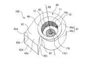
- FIG. 1 is a perspective view schematically showing a centrifugal fan according to Embodiment 1;
- FIG. FIG. 2 is an external view schematically showing the configuration of the centrifugal fan according to Embodiment 1 viewed parallel to the rotation axis;
- FIG. 3 is a schematic cross-sectional view of the centrifugal fan shown in FIG. 2 taken along the line AA.
- 2 is a perspective view of an impeller that constitutes the centrifugal fan according to Embodiment 1.
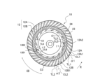
- FIG. 4 is a plan view of the impeller on the other surface side of the main plate of the centrifugal fan according to Embodiment 1.
- FIG. 7 is a cross-sectional view of the impeller shown in FIG. 6 taken along line BB.
- FIG. FIG. 5 is a side view of the impeller shown in FIG. 4;
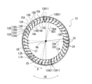
- FIG. 10 is a schematic diagram showing blades in a CC line cross section of the impeller shown in FIG. 9;
- FIG. 10 is a schematic diagram showing the exit angles of the blades in the CC line cross section of the impeller shown in FIG. 9;
- FIG. 10 is a schematic diagram showing blades in a DD cross section of the impeller shown in FIG. 9;
- FIG. 2 is an enlarged view conceptually showing a first example of blades forming the centrifugal fan according to Embodiment 1;
- FIG. 4 is an enlarged view conceptually showing a second example of blades forming the centrifugal fan according to Embodiment 1;
- FIG. 7 is an enlarged view conceptually showing a third example of the blades forming the centrifugal fan according to Embodiment 1;
- FIG. 8 is an enlarged view conceptually showing a fourth example of the blades that constitute the centrifugal fan according to Embodiment 1;
- FIG. 7 is an enlarged view conceptually showing a fifth example of the blades that constitute the centrifugal fan according to Embodiment 1;
- FIG. 11 is an enlarged view conceptually showing a sixth example of the blades forming the centrifugal fan according to Embodiment 1;
- FIG. 3 is a schematic diagram showing the relationship between the impeller and the scroll casing in the AA line cross section of the centrifugal fan shown in FIG. 2;
- FIG. 20 is a schematic diagram showing the relationship between the blades and the bellmouth in the impeller shown in FIG. 19 when viewed parallel to the rotation axis;
- FIG. 3 is a schematic diagram showing the relationship between the impeller and the scroll casing in the AA line cross section of the centrifugal fan shown in FIG. 2;
- FIG. 22 is a schematic diagram showing the relationship between the blades and the bellmouth in the impeller shown in FIG.
- FIG. 3 is a schematic diagram showing the relationship between the impeller and the bellmouth in the AA cross section of the centrifugal fan shown in FIG. 2;
- FIG. 3 is a cross-sectional view of a centrifugal fan according to a comparative example;
- FIG. 6 is a cross-sectional view schematically showing a centrifugal fan according to Embodiment 2;
- FIG. 11 is a perspective view of an air conditioner according to Embodiment 3;
- FIG. 10 is a diagram showing the internal configuration of an air conditioner according to Embodiment 3;
- FIG. 10 is a diagram showing the configuration of a refrigeration cycle apparatus according to Embodiment 4;
- FIG. 1 is a perspective view schematically showing centrifugal fan 100 according to Embodiment 1.
- FIG. 2 is an external view schematically showing the configuration of the centrifugal fan 100 according to Embodiment 1 viewed parallel to the rotation axis RA.
- FIG. 3 is a schematic cross-sectional view of the centrifugal fan 100 shown in FIG. 2 taken along the line AA. A basic structure of the centrifugal fan 100 will be described with reference to FIGS. 1 to 3.
- FIG. 1 is a perspective view schematically showing centrifugal fan 100 according to Embodiment 1.
- FIG. 2 is an external view schematically showing the configuration of the centrifugal fan 100 according to Embodiment 1 viewed parallel to the rotation axis RA.
- FIG. 3 is a schematic cross-sectional view of the centrifugal fan 100 shown in FIG. 2 taken along the line AA. A basic structure of the centrifugal fan 100 will be described with reference to FIGS. 1 to 3.
- the centrifugal fan 100 is a multi-blade centrifugal fan, and has an impeller 10 that generates an airflow and a scroll casing 40 that houses the impeller 10 inside.
- the centrifugal fan 100 is a double suction centrifugal fan in which air is sucked from both sides of the scroll casing 40 in the axial direction of the virtual rotation axis RA of the impeller 10 .
- the scroll casing 40 accommodates the impeller 10 for the centrifugal blower 100 therein and rectifies the air blown out from the impeller 10 .
- the scroll casing 40 has a scroll portion 41 and a discharge portion 42 .
- the scroll portion 41 forms an air passage that converts the dynamic pressure of the airflow generated by the impeller 10 into static pressure.
- the scroll portion 41 includes a side wall 44a formed with a case suction port 45 that covers the impeller 10 from the axial direction of the rotation axis RA of the boss portion 11b that constitutes the impeller 10 and takes in air, and a peripheral wall 44c surrounding the impeller 10 from the radial direction of the rotation axis RA.
- the scroll portion 41 is positioned between the discharge portion 42 and the winding start portion 41a of the peripheral wall 44c to form a curved surface. It has a guiding tongue 43 .
- the radial direction of the rotation axis RA is a direction perpendicular to the axial direction of the rotation axis RA.
- the internal space of the scroll portion 41 defined by the peripheral wall 44c and the side walls 44a is a space in which the air blown out from the impeller 10 flows along the peripheral wall 44c.
- the side walls 44 a are arranged on both sides of the impeller 10 in the axial direction of the rotation axis RA of the impeller 10 .
- a side wall 44 a of the scroll casing 40 is formed with a case suction port 45 so that air can flow between the impeller 10 and the outside of the scroll casing 40 .
- the case suction port 45 is formed in a circular shape, and the impeller 10 is arranged so that the center of the case suction port 45 and the center of the boss portion 11b of the impeller 10 are substantially aligned.
- the shape of the case suction port 45 is not limited to a circular shape, and may be other shapes such as an elliptical shape.
- the scroll casing 40 of the centrifugal fan 100 is a double suction type casing having side walls 44a formed with case suction ports 45 on both sides of the main plate 11 in the axial direction of the rotation axis RA of the boss portion 11b.
- the centrifugal blower 100 has two side walls 44 a in the scroll casing 40 .
- the two side walls 44a are formed to face each other via the peripheral wall 44c. More specifically, as shown in FIG. 3, the scroll casing 40 has a first side wall 44a1 and a second side wall 44a2 as side walls 44a.
- a first suction port 45a is formed in the first side wall 44a1.
- the first suction port 45a faces the plate surface of the main plate 11 on which the first side plate 13a, which will be described later, is arranged.
- a second suction port 45b is formed in the second side wall 44a2.
- the second suction port 45b faces the plate surface of the main plate 11 on which the second side plate 13b, which will be described later, is arranged.
- the case suction port 45 described above is a general term for the first suction port 45a and the second suction port 45b.
- a case suction port 45 provided in the side wall 44 a is formed by a bell mouth 46 . That is, the bellmouth 46 forms a case suction port 45 that communicates with the space formed by the main plate 11 and the plurality of blades 12 .
- the bellmouth 46 rectifies the gas sucked into the impeller 10 and causes it to flow into the suction port 10e of the impeller 10 .
- the bell mouth 46 is formed such that the opening diameter gradually decreases from the outside to the inside of the scroll casing 40 . Due to this configuration of the side wall 44 a , the air in the vicinity of the case suction port 45 smoothly flows along the bellmouth 46 and efficiently flows into the impeller 10 from the case suction port 45 .
- the peripheral wall 44c is a wall that guides the airflow generated by the impeller 10 along the curved wall surface to the discharge port 42a.
- the peripheral wall 44 c is a wall provided between the side walls 44 a facing each other, and forms a curved surface along the rotation direction R of the impeller 10 .
- the peripheral wall 44c is arranged parallel to the axial direction of the rotation axis RA of the impeller 10 and covers the impeller 10, for example. Note that the peripheral wall 44c may be inclined with respect to the axial direction of the rotation axis RA of the impeller 10, and is not limited to a configuration arranged parallel to the axial direction of the rotation axis RA.
- the peripheral wall 44c forms an inner peripheral surface that covers the impeller 10 from the radial direction of the boss portion 11b and faces a plurality of blades 12 described later.
- the peripheral wall 44 c faces the air blowing side of the blades 12 of the impeller 10 .
- the peripheral wall 44c is located at the boundary between the discharge portion 42 and the scroll portion 41 on the side away from the tongue portion 43 from the winding start portion 41a located at the boundary between the peripheral wall 44c and the tongue portion 43. It is provided along the rotation direction R of the impeller 10 to the winding end portion 41b.
- the winding start portion 41a is an upstream end portion of the peripheral wall 44c forming a curved surface in the flow direction of the gas that flows along the peripheral wall 44c in the internal space of the scroll casing 40 as the impeller 10 rotates.
- the winding end portion 41b is a downstream end portion of the peripheral wall 44c forming a curved surface in the flow direction of gas flowing along the peripheral wall 44c in the internal space of the scroll casing 40 as the impeller 10 rotates.
- the peripheral wall 44c is formed in a spiral shape.
- the spiral shape includes, for example, a logarithmic spiral, an Archimedean spiral, or a shape based on an involute curve.
- the inner peripheral surface of the peripheral wall 44c forms a curved surface that smoothly curves along the circumferential direction of the impeller 10 from the winding start portion 41a that is the beginning of the spiral winding to the winding end portion 41b that is the end of the spiral winding. .
- the air sent out from the impeller 10 smoothly flows in the direction of the discharge portion 42 through the gap between the impeller 10 and the peripheral wall 44c. Therefore, in the scroll casing 40 , the static pressure of air efficiently rises from the tongue portion 43 toward the discharge portion 42 .
- the discharge part 42 forms a discharge port 42a through which the airflow generated by the impeller 10 and passed through the scroll part 41 is discharged.
- the discharge part 42 is composed of a hollow tube having a rectangular cross section perpendicular to the direction in which air flows along the peripheral wall 44c.
- the cross-sectional shape of the discharge part 42 is not limited to a rectangle.
- the discharge portion 42 forms a flow path that guides the air sent out from the impeller 10 and flowing through the gap between the peripheral wall 44 c and the impeller 10 so as to be discharged to the outside of the scroll casing 40 .
- the discharge part 42 has an extension plate 42b, a diffuser plate 42c, a first side plate portion 42d, and a second side plate portion 42e.
- the extension plate 42b is formed integrally with the peripheral wall 44c so as to smoothly continue to the winding end portion 41b on the downstream side of the peripheral wall 44c.
- the diffuser plate 42c is formed integrally with the tongue portion 43 of the scroll casing 40 and faces the extension plate 42b.
- the diffuser plate 42c is formed at a predetermined angle with respect to the extension plate 42b so that the cross-sectional area of the flow path gradually expands along the direction in which the air in the discharge portion 42 flows.
- the first side plate portion 42d is formed integrally with the first side wall 44a1 of the scroll casing 40
- the second side plate portion 42e is formed integrally with the second side wall 44a2 on the opposite side of the scroll casing 40.
- the first side plate portion 42d and the second side plate portion 42e are formed between the extension plate 42b and the diffuser plate 42c. In this way, in the discharge part 42, a channel having a rectangular cross section is formed by the extension plate 42b, the diffuser plate 42c, the first side plate portion 42d, and the second side plate portion 42e.
- a tongue portion 43 is formed between the diffuser plate 42c of the discharge portion 42 and the winding start portion 41a of the peripheral wall 44c.
- the tongue portion 43 is formed with a predetermined radius of curvature, and the peripheral wall 44c is smoothly connected to the diffuser plate 42c via the tongue portion 43 .
- the tongue portion 43 suppresses the inflow of air from the winding end to the winding start of the spiral flow path.
- the tongue portion 43 is provided in the upstream portion of the ventilation passage, and divides the air flow in the rotation direction R of the impeller 10 and the air flow in the discharge direction from the downstream portion of the ventilation passage toward the discharge port 42a. have a role. Further, the static pressure of the air flowing into the discharge portion 42 increases while passing through the scroll casing 40 and becomes higher than that inside the scroll casing 40 . Therefore, the tongue portion 43 has a function of partitioning such a pressure difference.
- FIG. 4 is a perspective view of impeller 10 forming centrifugal fan 100 according to the first embodiment.
- FIG. 5 is a perspective view of the opposite side of the impeller 10 shown in FIG. 6 is a plan view of impeller 10 on one side of main plate 11 of centrifugal fan 100 according to Embodiment 1.
- FIG. 7 is a plan view of impeller 10 on the other side of main plate 11 of centrifugal fan 100 according to Embodiment 1.
- FIG. FIG. 8 is a cross-sectional view of the impeller 10 shown in FIG. 6 taken along line BB. Note that FIG. 6 omits the detailed configuration of the main plate 11 around the boss portion 11b.
- the impeller 10 will be described with reference to FIGS. 4 to 8.
- FIG. 6 omits the detailed configuration of the main plate 11 around the boss portion 11b. The impeller 10 will be described with reference to FIGS. 4 to 8.
- FIG. 6 omits the detailed configuration of the main plate 11 around the boss portion 11b.
- the impeller 10 is a centrifugal fan.
- the impeller 10 is connected to a motor (not shown) having a drive shaft.
- the impeller 10 is rotationally driven by a motor, and the centrifugal force generated by the rotation forces the air radially outward.
- the impeller 10 is rotated in a rotation direction R indicated by an arrow by a motor or the like.
- the impeller 10 includes a disk-shaped main plate 11, an annular side plate 13, and a plurality of blades 12 radially arranged around the rotation axis RA on the peripheral edge of the main plate 11. , has
- the main plate 11 may have a plate shape, and may have a shape other than a disk shape, such as a polygonal shape.
- the thickness of the main plate 11 may be formed so that the thickness of the wall increases toward the center in the radial direction about the rotation axis RA, as shown in FIG. It may be formed to have a constant thickness in the radial direction.
- the main plate 11 is not limited to being composed of a single plate-like member, and may be composed of a plurality of plate-like members that are integrally fixed.
- a boss portion 11b At the center of the main plate 11, there is provided a boss portion 11b to which the drive shaft of the motor is connected.
- a shaft hole 11b1 into which a drive shaft of a motor is inserted is formed in the boss portion 11b.
- the boss portion 11b is formed in a cylindrical shape, but the shape of the boss portion 11b is not limited to a cylindrical shape.
- the boss portion 11b may be formed in a columnar shape, for example, may be formed in a polygonal columnar shape.
- the main plate 11 is rotationally driven by a motor via the boss portion 11b.
- the impeller 10 has an annular side plate 13 attached to the ends of the plurality of blades 12 opposite to the main plate 11 in the axial direction of the rotation axis RA of the boss portion 11b.
- the side plate 13 is provided on the outer peripheral side surface 10 a of the impeller 10 and arranged to face the main plate 11 in the impeller 10 .
- the side plate 13 is provided outside the blade 12 in the radial direction about the rotation axis RA.
- the side plate 13 forms a gas suction port 10 e in the impeller 10 .
- the side plate 13 includes an annular first side plate 13a arranged to face the main plate 11, and a side plate 13a arranged to face the main plate 11 on the side opposite to the side on which the first side plate 13a is arranged with respect to the main plate 11. and an annular second side plate 13b.
- the side plate 13 is a general term for the first side plate 13a and the second side plate 13b, and the impeller 10 has the first side plate 13a on one side with respect to the main plate 11 in the axial direction of the rotation axis RA, and the side plate 13a on the other side. side has a second side plate 13b.
- the plurality of blades 12 have one end connected to the main plate 11 and the other end connected to the side plate 13, and are arranged in the circumferential direction CD about the virtual rotation axis RA of the main plate 11. It is Each of the blades 12 is arranged between the main plate 11 and the side plate 13 .
- the plurality of blades 12 are provided on both sides of the main plate 11 in the axial direction of the rotation axis RA of the boss portion 11b.
- Each blade 12 is arranged in the circumferential direction CD at a constant interval from each other in the peripheral portion of the main plate 11 .
- FIG. 9 is a side view of the impeller 10 shown in FIG.
- the impeller 10, as shown in FIGS. 4 and 9, has a first blower section 112a and a second blower section 112b.
- the first air blowing section 112 a and the second air blowing section 112 b are composed of a plurality of blades 12 and side plates 13 . More specifically, the first air blower 112a is composed of an annular first side plate 13a and a plurality of blades 12 arranged between the main plate 11 and the first side plate 13a.
- the second air blower 112b is composed of an annular second side plate 13b and a plurality of blades 12 arranged between the main plate 11 and the second side plate 13b.
- the first air blower 112 a is arranged on one surface side of the main plate 11
- the second air blower 112 b is arranged on the other surface side of the main plate 11 . That is, the plurality of blades 12 are provided on both sides of the main plate 11 in the axial direction of the rotation axis RA, and the first blower portion 112a and the second blower portion 112b are provided back-to-back through the main plate 11. ing. 4 and 9, the first air blower 112a is arranged above the main plate 11, and the second air blower 112b is arranged below the main plate 11. As shown in FIG.
- the first blower portion 112a and the second blower portion 112b only need to be provided back-to-back with the main plate 11 interposed therebetween.
- the second air blower 112b may be arranged on the upper side.
- the blades 12 collectively refer to the blades 12 forming the first blowing section 112a and the blades 12 forming the second blowing section 112b.
- the impeller 10 has a cylindrical shape with a plurality of blades 12 arranged on a main plate 11. As shown in FIG. The impeller 10 is provided on the side plate 13 side opposite to the main plate 11 in the axial direction of the rotation axis RA of the boss portion 11b, for allowing gas to flow into the space surrounded by the main plate 11 and the plurality of blades 12. A suction port 10e is formed.
- the impeller 10 has blades 12 and side plates 13 arranged on both sides of the plate surface forming the main plate 11, and suction ports 10e of the impeller 10 are formed on both sides of the plate surface forming the main plate 11.
- the impeller 10 is driven to rotate about the rotation axis RA by being driven by a motor (not shown). As the impeller 10 rotates, gas outside the centrifugal blower 100 passes through the case suction port 45 formed in the scroll casing 40 shown in FIG. is sucked into the space surrounded by the blades 12 of the As the impeller 10 rotates, the air sucked into the space surrounded by the main plate 11 and the plurality of blades 12 passes through the space between the blades 12 and the adjacent blades 12, and the diameter of the impeller 10 increases. direction outward.
- FIG. 10 is a schematic diagram showing blades 12 in a CC line cross section of impeller 10 shown in FIG.
- FIG. 11 is a schematic diagram showing the exit angles of the blades 12 in the CC line cross section of the impeller 10 shown in FIG.
- FIG. 12 is a schematic diagram showing blades 12 in a DD cross section of impeller 10 shown in FIG.
- An intermediate position MP of the impeller 10 shown in FIG. 9 indicates an intermediate position in the axial direction of the rotation axis RA among the plurality of blades 12 forming the first air blowing section 112a.
- An intermediate position MP of the impeller 10 shown in FIG. 9 indicates an intermediate position in the axial direction of the rotation axis RA in the plurality of blades 12 that constitute the second air blowing section 112b.
- the area from the intermediate position MP in the axial direction of the rotation axis RA to the main plate 11 is defined as the main plate side blade area 122a, which is the first area of the impeller 10.
- the region from the intermediate position MP in the axial direction of the rotating shaft RA to the end portion on the side plate 13 side is the side plate side blade region which is the second region of the impeller 10. 122b.
- each of the plurality of blades 12 has a first region positioned closer to the main plate 11 than the intermediate position MP in the axial direction of the rotation axis RA, and a second region positioned closer to the side plate 13 than the first region. have.
- the CC line cross section shown in FIG. 10 is the cross section of the plurality of blades 12 on the main plate 11 side of the impeller 10, that is, in the main plate side blade region 122a, which is the first region, as shown in FIG.
- the cross section of the blades 12 on the main plate 11 side is the first plane 71 perpendicular to the rotation axis RA, and is the first cross section of the impeller 10 obtained by cutting the portion of the impeller 10 closer to the main plate 11 .
- the portion of the impeller 10 near the main plate 11 is, for example, a portion closer to the main plate 11 than the intermediate position of the main plate-side blade region 122a in the axial direction of the rotation axis RA, or a portion of the blade in the axial direction of the rotation axis RA. This is the portion where the end of 12 on the side of the main plate 11 is located.
- the DD cross section shown in FIG. 12 is the cross section of the plurality of blades 12 on the side plate 13 side of the impeller 10, that is, in the side plate side blade region 122b, which is the second region, as shown in FIG.
- the cross section of the blades 12 on the side plate 13 side is a second plane 72 perpendicular to the rotation axis RA, and is the second cross section of the impeller 10 obtained by cutting a portion of the impeller 10 near the side plate 13 .
- the portion of the impeller 10 near the side plate 13 is, for example, a portion closer to the side plate 13 than the intermediate position of the side plate-side blade region 122b in the axial direction of the rotation axis RA, or a portion of the blade in the axial direction of the rotation axis RA.
- 12 is a portion where the end portion on the side plate 13 side of 12 is located.
- the basic configuration of the blades 12 in the second air blowing section 112b is the same as the basic configuration of the blades 12 in the first air blowing section 112a. That is, in the plurality of blades 12 forming the second air blower 112b, the region from the intermediate position MP in the axial direction of the rotation axis RA to the main plate 11 is defined as the main plate side blade region 122a, which is the first region of the impeller 10. In addition, in the plurality of blades 12 constituting the second air blowing section 112b, the region from the intermediate position MP in the axial direction of the rotation axis RA to the end on the second side plate 13b side is the side plate side that is the second region of the impeller 10 Let it be the blade region 122b.
- the basic configuration of the first blowing section 112a and the basic configuration of the second blowing section 112b are the same, but the configuration of the impeller 10 is limited to this configuration. Instead, the first air blower 112a and the second air blower 112b may have different configurations.
- the configuration of the blades 12 described below may have both the first blower section 112a and the second blower section 112b, or may have either one.
- the plurality of blades 12 has a plurality of first blades 12A and a plurality of second blades 12B.
- the plurality of blades 12 alternately arrange the first blades 12A and one or more second blades 12B.
- the impeller 10 has two second blades 12B arranged between the first blade 12A and the first blade 12A arranged next to it in the rotation direction R.
- the number of the second blades 12B arranged between the first blade 12A and the first blade 12A arranged next to it in the rotation direction R is not limited to two, and is one or three or more. may be That is, at least one second blade 12B of the plurality of second blades 12B is arranged between two first blades 12A adjacent to each other in the circumferential direction CD among the plurality of first blades 12A.
- the first blade 12A has an inner peripheral end 14A and an outer peripheral end 15A in a first cross section of the impeller 10 cut by a first plane 71 perpendicular to the rotation axis RA.
- the inner peripheral end 14A is located on the side of the rotation axis RA in the radial direction centered on the rotation axis RA, and the outer peripheral end 15A is located on the outer peripheral side of the inner peripheral end 14A in the radial direction.
- the inner peripheral end 14A is arranged forward of the outer peripheral end 15A in the rotational direction R of the impeller 10 .
- the inner peripheral end 14A becomes the front edge 14A1 of the first blade 12A
- the outer peripheral end 15A becomes the rear edge 15A1 of the first blade 12A.
- 14 first blades 12A are arranged in the impeller 10, but the number of the first blades 12A is not limited to 14, and may be less than 14. Well, it can be more than 14 sheets.
- the second blade 12B has an inner peripheral end 14B and an outer peripheral end 15B in the first cross section of the impeller 10 cut by the first plane 71 perpendicular to the rotation axis RA.
- the inner peripheral end 14B is located on the side of the rotation axis RA in the radial direction centered on the rotation axis RA, and the outer peripheral end 15B is located on the outer peripheral side of the inner peripheral end 14B in the radial direction.
- the inner peripheral end 14B is arranged forward of the outer peripheral end 15B in the rotational direction R of the impeller 10 .
- the inner peripheral end 14B is the leading edge 14B1 of the second blade 12B
- the outer peripheral end 15B is the trailing edge 15B1 of the second blade 12B.
- 28 second blades 12B are arranged in the impeller 10, but the number of the second blades 12B is not limited to 28, and may be less than 28. Well, it can be more than 28 sheets.
- the relationship between the first blade 12A and the second blade 12B will be explained.
- the blade length of the first blade 12A increases to the blade length of the second blade 12B. are formed to be equal in length.
- the blade length of the first blade 12A is longer than the blade length of the second blade 12B. and is longer as it approaches the main plate 11.
- the blade length of the first blade 12A is longer than the blade length of the second blade 12B in at least part of the direction along the rotation axis RA.
- the blade length used here is the length of the first blade 12A in the radial direction of the impeller 10 and the length of the second blade 12B in the radial direction of the impeller 10.
- wing 12A be ID1.
- the diameter of a circle C3 centered on the rotation axis RA and passing through the outer peripheral ends 15A of the plurality of first blades 12A, that is, the outer diameter of the first blades 12A, is defined as an outer diameter OD1.
- the ratio between the inner diameter of the first blade 12A and the outer diameter of the first blade 12A is 0.7 or less. That is, the plurality of first blades 12A has an inner diameter ID1 formed by the inner peripheral end 14A of each of the plurality of first blades 12A and an outer diameter OD1 formed by the outer peripheral end 15A of each of the plurality of first blades 12A. is 0.7 or less.
- the blade length of the blades in a cross section perpendicular to the rotation axis is shorter than the width dimension of the blades in the direction of the rotation axis.
- the maximum blade length of the first blade 12A that is, the blade length at the end portion of the first blade 12A near the main plate 11 is the width dimension W (see FIG. 9) of the first blade 12A in the direction of the rotation axis. is shorter than
- the diameter of a circle C2 passing through the inner peripheral ends 14B of the plurality of second blades 12B around the rotation axis RA is set to an inner diameter ID2 larger than the inner diameter ID1.
- the blade length L2a of the second blade 12B in the first section is shorter than the blade length L1a of the first blade 12A in the same section (blade length L2a ⁇ blade length L1a).
- the ratio of the inner diameter of the second blade 12B to the outer diameter of the second blade 12B is 0.7 or less. That is, the plurality of second blades 12B has an inner diameter ID2 formed by the inner peripheral end 14B of each of the plurality of second blades 12B and an outer diameter OD2 formed by the outer peripheral end 15B of each of the plurality of second blades 12B. is 0.7 or less.
- inner diameter ID3 is larger than the inner diameter ID1 of the first section (inner diameter ID3>inner diameter ID1).
- the diameter of a circle C8 centered on the rotation axis RA and passing through the outer peripheral end 15A of the first blade 12A is defined as an outer diameter OD3.
- the diameter of a circle C7 centered on the rotation axis RA and passing through the inner peripheral end 14B of the second blade 12B is defined as an inner diameter ID4.
- the diameter of a circle C8 centered on the rotation axis RA and passing through the outer peripheral end 15B of the second blade 12B is defined as an outer diameter OD4.
- the ratio between the inner diameter ID1 of the first blade 12A and the outer diameter OD1 of the first blade 12A is 0.7 or less.
- the ratio of the blade inner diameter of the blades 12 to the blade outer diameter of the blades 12 is 0.7 or less.
- the blade inner diameters of the plurality of blades 12 are formed by the inner peripheral ends of the plurality of blades 12 . That is, the blade inner diameters of the plurality of blades 12 are formed by the front edges 14A1 of the plurality of blades 12. As shown in FIG. Further, the blade outer diameters of the plurality of blades 12 are configured by the outer peripheral ends of the plurality of blades 12 . That is, the blade outer diameters of the plurality of blades 12 are defined by the trailing edges 15A1 and 15B1 of the plurality of blades 12 .
- the first blade 12A has a relationship of blade length L1a>blade length L1b in comparison between the first cross section shown in FIG. 10 and the second cross section shown in FIG. That is, each of the plurality of blades 12 has a portion in which the blade length in the first region is longer than the blade length in the second region. More specifically, the first blade 12A has a portion formed so that the blade length becomes shorter from the main plate 11 side toward the side plate 13 side in the axial direction of the rotation axis RA.
- the second blade 12B has a relationship of blade length L2a>blade length L2b in comparison between the first cross section shown in FIG. 10 and the second cross section shown in FIG. That is, the second blade 12B has a portion formed so that the blade length becomes shorter from the main plate 11 side toward the side plate 13 side in the axial direction of the rotation axis RA. That is, each of the plurality of blades 12 is formed so that the blade length becomes shorter from the side of the main plate 11 toward the side of the side plate 13 .
- Each of the plurality of blades 12 has a shape in which the size of the blade length changes continuously from the side of the main plate 11 to the side of the side plate 13 .
- the shape of the plurality of blades 12 is not limited to this shape, and the plurality of blades 12 may have a portion with a constant blade length between the main plate 11 and the side plate 13 . That is, the plurality of blades 12 may have a portion that has a constant inner diameter ID and is not inclined with respect to the rotation axis RA.
- the front edges of the first blade 12A and the second blade 12B are inclined such that the blade inner diameter increases from the main plate 11 side toward the side plate 13 side. That is, the plurality of blades 12 are formed such that the inner diameter of the blades increases from the main plate 11 side toward the side plate 13 side, and the inner peripheral end 14A constituting the front edge 14A1 is inclined away from the rotation axis RA. It has an inclined portion 141A. Similarly, the plurality of blades 12 are formed such that the inner diameter of the blades increases from the side of the main plate 11 toward the side of the side plate 13, and the inner peripheral end 14B forming the leading edge 14B1 is separated from the rotation axis RA. It has an inclined portion 141B.
- the first blade 12A includes a first outer peripheral side blade portion 12A1 including an outer peripheral end 15A, and an inner peripheral end 14A. and a configured first inner circumferential side wing portion 12A2.
- the first outer peripheral blade portion 12A1 configures the outer peripheral side of the first blade 12A
- the first inner peripheral blade portion 12A2 configures the inner peripheral side of the first blade 12A. That is, in the radial direction of the impeller 10, the first blade 12A is composed of a first inner peripheral blade portion 12A2 and a first outer peripheral blade portion 12A1 in order from the rotation axis RA toward the outer peripheral side.
- the first inner peripheral blade portion 12A2 and the first outer peripheral blade portion 12A1 are integrally formed.
- the first inner peripheral blade portion 12A2 constitutes the leading edge 14A1 of the first blade 12A
- the first outer peripheral blade portion 12A1 constitutes the trailing edge 15A1 of the first blade 12A.
- the first inner peripheral blade portion 12A2 extends from the inner peripheral end 14A forming the leading edge 14A1 toward the outer peripheral side.
- the region forming the first outer peripheral blade portion 12A1 of the first blade 12A is defined as a first outer peripheral region 12A11, and the region forming the first inner peripheral blade portion 12A2 of the first blade 12A. is defined as the first inner peripheral side area 12A21.
- the first blade 12A has a portion in which the first inner peripheral region 12A21 is larger than the first outer peripheral region 12A11 in the radial direction of the impeller 10 .
- the impeller 10 in the radial direction of the impeller 10, in the main plate side blade region 122a that is the first region and the side plate side blade region 122b that is the second region shown in FIG. It has a portion having a relationship with the inner circumference side region 12A21.
- the ratio of the first inner peripheral side blade portion 12A2 occupied by It has a portion larger than the proportion occupied by one outer peripheral side wing portion 12A1.
- the second blade 12B includes a second outer peripheral side blade portion 12B1 including an outer peripheral end 15B and an inner peripheral end 14B, and includes a turbo blade constituting a trailing blade. and a second inner circumferential side blade portion 12B2 configured as a facing blade.
- the second outer peripheral blade portion 12B1 constitutes the outer peripheral side of the second blade 12B
- the second inner peripheral blade portion 12B2 constitutes the inner peripheral side of the second blade 12B. That is, in the radial direction of the impeller 10, the second blade 12B is composed of a second inner peripheral blade portion 12B2 and a second outer peripheral blade portion 12B1 in this order from the rotation axis RA toward the outer peripheral side.
- the second inner peripheral blade portion 12B2 and the second outer peripheral blade portion 12B1 are integrally formed.
- the second inner peripheral blade portion 12B2 forms the leading edge 14B1 of the second blade 12B
- the second outer peripheral blade portion 12B1 forms the trailing edge 15B1 of the second blade 12B.
- the second inner peripheral blade portion 12B2 extends from the inner peripheral end 14B forming the leading edge 14B1 toward the outer peripheral side.
- the region forming the second outer peripheral blade portion 12B1 of the second blade 12B is defined as a second outer peripheral region 12B11, and the region forming the second inner peripheral blade portion 12B2 of the second blade 12B. is defined as a second inner circumference side region 12B21.
- the second blade 12B has a portion in which the second inner peripheral region 12B21 is larger than the second outer peripheral region 12B11 in the radial direction of the impeller 10 .
- the impeller 10 in the radial direction of the impeller 10, in the main plate side blade region 122a that is the first region and the side plate side blade region 122b that is the second region shown in FIG. It comprises a portion having a relationship of the side region 12B21.
- the ratio of the second inner peripheral side blade portion 12B2 occupied is the second. It has a portion larger than the ratio of the second outer peripheral side wing portion 12B1.
- the region of the inner peripheral blade portion is larger than the region of the outer peripheral blade portion.
- the ratio of the inner peripheral blade portion is larger than the ratio of the outer peripheral blade portion. It has a portion having a relation of peripheral side area ⁇ peripheral side area.
- each of the plurality of blades 12 has a portion in the first region and the second region in which the ratio of the inner peripheral blade portion in the radial direction is larger than the ratio of the outer peripheral blade portion.
- the relationship of the occupation ratios of the outer peripheral blade portion and the inner peripheral blade portion in the radial direction of the rotation axis RA is established in all regions of the main plate side blade region 122a that is the first region and the side plate side blade region 122b that is the second region. You may
- the ratio of the inner peripheral blade portion in the radial direction of the impeller 10 is larger than the ratio of the outer peripheral blade portion in all of the main plate side blade region 122a and the side plate side blade region 122b. is not limited to In each of the plurality of blades 12, in the first region and the second region, the ratio of the inner peripheral blade portion in the radial direction is equal to or smaller than the ratio of the outer peripheral blade portion. good.
- the impeller 10 has a first blade portion 23 and a second blade portion 24 .
- the first wing portion 23 is composed of a first outer peripheral wing portion 12A1 or a second outer peripheral wing portion 12B1.
- the first wing portion 23 connects with the side plate 13 .
- the first blade portion 23 includes the outer peripheral end 15A or the outer peripheral end 15B, and constitutes the blade 12 having an outlet angle ⁇ 1 and an outlet angle ⁇ 2, which will be described later, of 90 degrees or less.
- the first blade portion 23 constitutes a turbo blade serving as a trailing blade when the exit angle ⁇ 1 and the exit angle ⁇ 2 are less than 90 degrees.
- the first blade portion 23 is configured as a radial blade linearly extending in the radial direction of the impeller 10 when the outlet angle ⁇ 1 and the outlet angle ⁇ 2 are 90 degrees. That is, the first outer peripheral blade portion 12A1 is configured by a turbo blade portion or a radial blade portion. Similarly, the second outer peripheral blade portion 12B1 is composed of a turbo blade portion or a radial blade portion.
- the second wing portion 24 is composed of the first inner circumferential side wing portion 12A2 or the second inner circumferential side wing portion 12B2. That is, the second blade portion 24 is a portion of the impeller 10 that includes turbo blades.
- the second blade portion 24 includes a turbo blade that includes the inner peripheral end 14A or the inner peripheral end 14B and constitutes a rearward blade, and when viewed in the axial direction of the rotation axis RA, the blade 12 in the axial direction of the rotation axis RA , on the main plate 11 side protrudes inward from the bell mouth 46 .
- the first wing portion 23 and the second wing portion 24 are bent so as to include at least one arc-shaped portion when viewed in the axial direction of the rotation axis RA.
- the first wing portion 23 and the second wing portion 24 are formed such that the radius of curvature of the first wing portion 23 is smaller than the radius of curvature of the second wing portion 24 .
- the shape of the second wing portion 24 is not limited to the bent shape as described above.
- the first wing portion 23 is bent so as to include at least one or more circular arc-shaped portions when viewed in the axial direction of the rotation axis RA, and the second wing portion 24 extends along the rotation axis RA. It may be formed in a straight line when viewed in the axial direction.
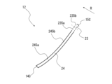
- FIG. 13 is an enlarged view conceptually showing a first example of the blades 12 that constitute the centrifugal fan 100 according to the first embodiment.
- the blade 12 of the first example will be explained using FIG. 13 .
- the blade 12 may be either the first blade 12A or the second blade 12B, and is a generic term for the first blade 12A and the second blade 12B.
- the inner peripheral end 14C is a general term for the inner peripheral end 14A of the first blade 12A and the inner peripheral end 14B of the second blade 12B.
- the outer peripheral end 15C is a general term for the outer peripheral end 15A of the first blade 12A and the outer peripheral end 15B of the second blade 12B.
- the exit angle ⁇ is a general term for exit angles ⁇ 1 and ⁇ 2, which will be described later.
- the blade 12 has a first wing portion 23 and a second wing portion 24 .
- the first blade portion 23 has a portion forming a turbo blade that becomes a trailing blade when the exit angle ⁇ is less than 90 degrees.
- the first blade portion 23 has a portion configured as a radial blade extending linearly in the radial direction of the impeller 10 when the exit angle ⁇ is 90 degrees.
- the first wing portion 23 has an outer peripheral first arc portion 231 .
- the outer peripheral first arcuate portion 231 is a portion formed in an arcuate shape when viewed in the axial direction of the rotation axis RA.
- the first arcuate portion 231 on the outer peripheral side has a convex shape in the counter-rotational direction, which is the opposite direction to the rotation direction R of the blades 12, and is open in the rotation direction R. is formed in The second wing portion 24 is formed in a straight line when viewed in the axial direction of the rotation axis RA.
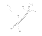
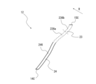
- FIG. 14 is an enlarged view conceptually showing a second example of the blades 12 that constitute the centrifugal fan 100 according to the first embodiment.
- the blade 12 of the second example will be explained with reference to FIG. 14 .
- Parts having the same configuration as in FIG. 13 are denoted by the same reference numerals, and descriptions thereof are omitted.
- the first wing portion 23 has an outer peripheral first arc portion 232 .
- the outer peripheral first arcuate portion 232 is a portion formed in an arcuate shape when viewed in the axial direction of the rotating shaft RA.
- the outer peripheral first arc portion 232 When viewed in the axial direction of the rotation axis RA, the outer peripheral first arc portion 232 has a convex shape in the counter-rotational direction opposite to the rotation direction R of the blades 12, and is open in the rotation direction R. is formed in
- the second wing portion 24 has an inner peripheral first arc portion 242 .
- the inner circumference side first arc portion 242 is a portion formed in an arc shape when viewed in the axial direction of the rotation axis RA.
- the inner peripheral first circular arc portion 242 has a convex shape in the counter-rotational direction opposite to the rotational direction R of the blades 12 when viewed in the axial direction of the rotation axis RA, and is open in the rotational direction R. formed into a shape.
- the radius of curvature of the first arcuate portion 232 on the outer peripheral side be the radius of curvature r.
- a radius of curvature R is the radius of curvature of the first arc portion 242 on the inner peripheral side.
- the blade 12 of the second example is formed so as to satisfy the relational expression of curvature radius r>curvature radius R. That is, the blade 12 of the second example is formed such that the radius of curvature of the first arcuate portion 232 on the outer peripheral side is larger than the radius of curvature of the first arcuate portion 242 on the inner peripheral side.
- FIG. 15 is an enlarged view conceptually showing a third example of the blades 12 that constitute the centrifugal fan 100 according to the first embodiment.
- a blade 12 of a third example will be described with reference to FIG. 15 .
- Parts having the same configuration as in FIG. 13 are denoted by the same reference numerals, and descriptions thereof are omitted.
- the first wing portion 23 has an outer peripheral first arc portion 233 .
- the outer peripheral first arcuate portion 233 is a portion formed in an arcuate shape when viewed in the axial direction of the rotating shaft RA.
- the outer peripheral first arc portion 233 When viewed in the axial direction of the rotation axis RA, the outer peripheral first arc portion 233 has a convex shape in the counter-rotational direction, which is the direction opposite to the rotation direction R of the blades 12, and a shape that opens in the rotation direction R. is formed in
- the second wing portion 24 has an inner peripheral first circular arc portion 243a and an inner peripheral second circular arc portion 243b.
- the first inner arc portion 243a is located on the side of the rotation axis RA, that is, on the inner circumference side of the impeller 10 with respect to the second inner arc portion 243b.
- the second inner arc portion 243b is located on the side plate 13 side, that is, on the outer circumference side of the impeller 10 with respect to the first inner arc portion 243a.
- the first inner arc portion 243a and the second inner arc portion 243b are arcuate portions when viewed in the axial direction of the rotation axis RA.
- the inner peripheral first circular arc portion 243a and the inner peripheral second circular arc portion 243b are convex in the counter-rotational direction, which is the direction opposite to the rotational direction R of the blades 12 when viewed in the axial direction of the rotation axis RA. , and is formed in a shape that is open in the rotation direction R.
- the radius of curvature of the first arcuate portion 233 on the outer peripheral side be the radius of curvature r.
- the radius of curvature of the inner peripheral side first circular arc portion 243a is defined as a radius of curvature R1.
- the curvature radius of the inner peripheral side second circular arc portion 243b is defined as a curvature radius R2.
- the blade 12 of the third example is formed to satisfy the relational expression of curvature radius r>curvature radius R2>curvature radius R1.
- the blade 12 of the third example is formed so that the radius of curvature of the first arcuate portion 233 on the outer circumference side is larger than the radius of curvature of the second arcuate portion 243b on the inner circumference side.
- the radius of curvature of the portion 243b is formed to be larger than the radius of curvature of the first inner arc portion 243a.
- the blade 12 of the third example is formed so that the radius of curvature of the arcuate portion increases from the inner peripheral side to the outer peripheral side.
- FIG. 16 is an enlarged view conceptually showing a fourth example of the blades 12 that constitute the centrifugal fan 100 according to the first embodiment.
- a blade 12 of a fourth example will be described with reference to FIG. 16 .
- Parts having the same configuration as in FIG. 13 are denoted by the same reference numerals, and descriptions thereof are omitted.
- the first wing portion 23 has a first outer arc portion 234a and a second outer arc portion 234b.
- the outer peripheral first circular arc portion 234a is located on the rotation axis RA side, that is, the inner peripheral side of the impeller 10 with respect to the outer peripheral second circular arc portion 234b.
- the second outer arc portion 234b is positioned on the side plate 13 side, that is, on the outer circumference side of the impeller 10 with respect to the first outer arc portion 234a.
- the first outer arc portion 234a and the second outer arc portion 234b are arc-shaped portions when viewed in the axial direction of the rotation axis RA.
- the outer peripheral first arc portion 234a When viewed in the axial direction of the rotation axis RA, the outer peripheral first arc portion 234a has a convex shape in the counter-rotational direction opposite to the rotation direction R of the blades 12, and is open in the rotation direction R.
- the outer circumferential second arc portion 234b has a convex shape in the rotation direction R of the blades 12 when viewed in the axial direction of the rotation axis RA, and is convex in the counter-rotational direction opposite to the rotation direction R of the blades 12. It has an open shape.
- the second wing portion 24 has an inner peripheral first arc portion 244 .
- the inner peripheral first arcuate portion 244 is a portion formed in an arcuate shape when viewed in the axial direction of the rotation axis RA.
- the inner peripheral side first circular arc portion 244 has a convex shape in the counter-rotational direction, which is the direction opposite to the rotational direction R of the blades 12 when viewed in the axial direction of the rotation axis RA, and is open in the rotational direction R. formed into a shape.
- the radius of curvature of the first arcuate portion 234a on the outer peripheral side be the radius of curvature r1.
- the radius of curvature of the second arc portion 234b on the outer peripheral side be a radius of curvature r2.
- a radius of curvature R is the radius of curvature of the first arcuate portion 244 on the inner peripheral side.
- the blade 12 of the fourth example is formed so as to satisfy the relational expression of curvature radius R>curvature radius r1>curvature radius r2.
- the blade 12 of the fourth example is formed to satisfy the relational expression of curvature radius r1>curvature radius R>curvature radius r2.
- the blade 12 of the fourth example is formed such that the radius of curvature of the first arcuate portion 234a on the outer peripheral side is larger than the radius of curvature of the second arcuate portion 234b on the outer peripheral side. Further, the blade 12 of the fourth example is formed such that the radius of curvature of the first inner arc portion 244 is larger than the radius of curvature of the second outer arc portion 234b. The blade 12 of the fourth example is formed so that the radius of curvature of the arc-shaped portion on the outermost side is the smallest when the curvature radii of the arc-shaped portions are compared.
- FIG. 17 is an enlarged view conceptually showing a fifth example of the blades 12 forming the centrifugal fan 100 according to the first embodiment.
- the blade 12 of the fifth example will be explained with reference to FIG. 17 . Parts having the same configuration as in FIG. 13 are denoted by the same reference numerals, and descriptions thereof are omitted.
- the first wing portion 23 has a first outer arc portion 235a and a second outer arc portion 235b.
- the first outer arc portion 235a is located on the inner circumference side of the impeller 10 with respect to the second outer arc portion 235b.
- the second outer arc portion 235b is located on the side plate 13 side, that is, on the outer circumference side of the impeller 10 with respect to the first outer arc portion 235a.
- the first outer arc portion 235a and the second outer arc portion 235b are arc-shaped portions when viewed in the axial direction of the rotation axis RA.
- the outer peripheral first arc portion 235a When viewed in the axial direction of the rotation axis RA, the outer peripheral first arc portion 235a has a convex shape in the counter-rotational direction, which is the direction opposite to the rotation direction R of the blade 12, and is open in the rotation direction R. is formed in The outer circumference-side second circular arc portion 235b has a convex shape in the rotation direction R of the blade 12 when viewed in the axial direction of the rotation axis RA, and is convex in the opposite rotation direction to the rotation direction R of the blade 12. It has an open shape.
- the second wing portion 24 has an inner peripheral first circular arc portion 245a and an inner peripheral second circular arc portion 245b.
- the inner peripheral first circular arc portion 245a is located on the rotation axis RA side, that is, the inner peripheral side of the impeller 10 with respect to the inner peripheral second circular arc portion 245b.
- the second inner arc portion 245b is positioned on the side plate 13 side, that is, on the outer circumference side of the impeller 10 with respect to the first inner arc portion 245a.
- the first inner arc portion 245a and the second inner arc portion 245b are arcuate portions when viewed in the axial direction of the rotation axis RA.
- the inner peripheral first circular arc portion 245a and the inner peripheral second circular arc portion 245b are convex in the counter-rotational direction opposite to the rotational direction R of the blades 12 when viewed in the axial direction of the rotation axis RA. , and is formed in a shape that is open in the rotation direction R.
- the radius of curvature of the first arc portion 235a on the outer peripheral side is defined as radius of curvature r1.
- the radius of curvature of the second arc portion 235b on the outer peripheral side be a radius of curvature r2.
- the curvature radius of the inner peripheral side first circular arc portion 245a is defined as a curvature radius R1.
- the radius of curvature of the second arcuate portion 245b on the inner peripheral side be a radius of curvature R2.
- the blade 12 of the fifth example is formed to satisfy the relational expression of curvature radius R2>curvature radius r1>curvature radius R1>curvature radius r2.
- the blade 12 of the fifth example is formed to satisfy the relational expression of curvature radius r1>curvature radius R2>curvature radius R1>curvature radius r2.
- the curvature radius of the outer circumference side first arc portion 235a, the curvature radius of the inner circumference side first arc portion 245a, or the curvature radius of the inner circumference side second arc portion 245b is the outer circumference side. It is formed so as to be larger than the radius of curvature of the second arc portion 235b. Further, in the blade 12 of the fifth example, the radius of curvature of the outer first arc portion 235a or the radius of curvature of the second inner arc portion 245b is larger than the radius of curvature of the first inner arc portion 245a. designed to grow.
- the blade 12 of the fifth example is formed so that the radius of curvature of the arc-shaped portion on the outermost side is the smallest when the curvature radii of the arc-shaped portions are compared.
- the innermost arc is formed. It is formed so that the radius of curvature of the curved portion is the smallest.
- FIG. 18 is an enlarged view conceptually showing a sixth example of the blades 12 that constitute the centrifugal fan 100 according to the first embodiment.
- the blade 12 of the sixth example will be described with reference to FIG. 18 . Parts having the same configuration as in FIG. 13 are denoted by the same reference numerals, and descriptions thereof are omitted.
- the first wing portion 23 has a first outer arc portion 236a and a second outer arc portion 236b.
- the first outer arc portion 236a is located on the inner circumference side of the impeller 10 with respect to the second outer arc portion 236b on the rotation axis RA side.
- the second outer arc portion 236b is positioned on the side plate 13 side, that is, on the outer circumference side of the impeller 10 with respect to the first outer arc portion 236a.
- the first outer arc portion 236a and the second outer arc portion 236b are arc-shaped portions when viewed in the axial direction of the rotation axis RA.
- the first outer arc portion 236a and the second outer arc portion 236b are convex in the counter-rotational direction, which is the opposite direction to the rotation direction R of the blades 12, when viewed in the axial direction of the rotation axis RA. , is formed in a shape that is open in the direction of rotation R.
- the second wing portion 24 has an inner peripheral first arc portion 246 .
- the inner peripheral first arcuate portion 246 is a portion formed in an arcuate shape when viewed in the axial direction of the rotation axis RA.
- the inner peripheral first circular arc portion 246 has a convex shape in the counter-rotational direction, which is the direction opposite to the rotational direction R of the blades 12 when viewed in the axial direction of the rotation axis RA, and is open in the rotational direction R. formed into a shape.
- the radius of curvature of the first arc portion 236a on the outer peripheral side is defined as radius of curvature r1.
- the radius of curvature of the second circular arc portion 236b on the outer peripheral side be a radius of curvature r2.
- a radius of curvature R is the radius of curvature of the first arcuate portion 246 on the inner peripheral side.
- the blade 12 of the sixth example is formed so as to satisfy the relational expression of curvature radius R>curvature radius r1>curvature radius r2.
- the blade 12 of the sixth example is formed to satisfy the relational expression of curvature radius r2>curvature radius R>curvature radius r1.
- the blade 12 of the sixth example is formed such that the radius of curvature of the first inner arc portion 246 is larger than the radius of curvature of the first outer arc portion 236a.
- a portion of the first blade portion 23 is bent so as to include at least one arc-shaped portion when viewed in the axial direction of the rotation axis RA.
- the arc-shaped portion of the first wing portion 23 is connected to the inner peripheral end of the side plate 13 and formed integrally with the side plate 13 .
- a portion of the second wing portion 24 is bent so as to include at least one arc-shaped portion when viewed in the axial direction of the rotation axis RA. It is
- the exit angle of the first outer peripheral blade portion 12A1 of the first blade 12A in the first cross section is defined as the exit angle ⁇ 1. That is, in the first cross section, the exit angle of the first blade portion 23 forming the first outer circumference side blade portion 12A1 is assumed to be the exit angle ⁇ 1.
- the exit angle ⁇ 1 is defined as the angle formed between the tangent line TL1 of the circle and the center line CL1 of the first blade portion 23 at the outer peripheral end 15A at the intersection of the arc of the circle C3 centered on the rotation axis RA and the outer peripheral end 15A. do.
- This exit angle ⁇ 1 is formed at an angle of 90 degrees or less.
- the exit angle ⁇ 1 is an angle on the counter-rotational direction side with respect to the center line CL1 of the first blade portion 23 in the circumferential direction CD.
- the exit angle of the second outer peripheral blade portion 12B1 of the second blade 12B in the same cross section is assumed to be the exit angle ⁇ 2. That is, in the first cross section, the exit angle of the first blade portion 23 forming the second outer circumference side blade portion 12B1 is assumed to be the exit angle ⁇ 2.
- the exit angle ⁇ 2 is defined as the angle formed by the tangent line TL2 of the circle and the center line CL2 of the first blade 23 at the outer peripheral end 15B at the intersection of the arc of the circle C3 centered on the rotation axis RA and the outer peripheral end 15B. do.
- the exit angle ⁇ 2 is formed at an angle of 90 degrees or less.
- the exit angle ⁇ 2 is an angle on the counter-rotational direction side with respect to the center line CL2 of the first blade portion 23 in the circumferential direction CD.
- the plurality of blades 12 are not limited to a configuration in which the outlet angle ⁇ 2 of the second outer peripheral blade portion 12B1 and the outlet angle ⁇ 1 of the first outer peripheral blade portion 12A1 are equal.
- the plurality of blades 12 may be formed with an exit angle ⁇ 2 and an exit angle ⁇ 1 of 90 degrees or less, respectively, and may be formed with an exit angle ⁇ 2 and an exit angle ⁇ 1 different from each other.
- the first blade portion 23 constituting the first outer peripheral blade portion 12A1 and the second outer peripheral blade portion 12B1 is formed in an arc shape so as to be convex in the direction opposite to the rotation direction R when viewed parallel to the rotation axis RA. ing.
- the impeller 10 has the same outlet angle ⁇ 1 of the first outer peripheral blade portion 12A1 and the outlet angle ⁇ 2 of the second outer peripheral blade portion 12B1 in the second cross section shown in FIG. That is, each of the plurality of blades 12 has a first blade portion 23 formed from the main plate 11 to the side plate 13 with an exit angle of 90 degrees or less.
- the exit angle of the first inner circumferential side blade portion 12A2 of the first blade 12A in the first cross section is defined as the exit angle ⁇ 1.
- the exit angle ⁇ 1 is the angle formed by the tangent line TL3 of the circle and the center line CL3 of the first inner wing 12A2 at the intersection of the arc of the circle C4 centered on the rotation axis RA and the first inner wing 12A2. defined as This exit angle ⁇ 1 is an angle smaller than 90 degrees.
- the outlet angle ⁇ 1 is an angle on the counter-rotational direction side with respect to the center line CL3 of the second blade portion 24 in the circumferential direction CD.
- the exit angle of the second inner peripheral blade portion 12B2 of the second blade 12B in the same cross section is defined as the exit angle ⁇ 2.
- the outlet angle ⁇ 2 is the angle formed by the tangent line TL4 of the circle and the center line CL4 of the second inner blade portion 12B2 at the intersection of the arc of the circle C4 centered on the rotation axis RA and the second inner blade portion 12B2. defined as Exit angle ⁇ 2 is an angle smaller than 90 degrees.
- the exit angle ⁇ 2 is an angle on the counter-rotational direction side with respect to the center line CL3 of the second blade portion 24 in the circumferential direction CD.
- the impeller 10 also has an outlet angle ⁇ 1 and an outlet angle ⁇ 2 smaller than 90 degrees in the second cross section.
- the inlet angle of the first inner peripheral blade portion 12A2 of the first blade 12A in the first cross section is ⁇ 1.
- the entrance angle ⁇ 1 is the angle formed between the tangent line TL5 of the circle and the center line CL5 of the first inner blade portion 12A2 at the intersection of the arc of the circle C1 centered on the rotation axis RA and the first inner blade portion 12A2. defined as That is, the portion of the blade 12 forming the inlet angle ⁇ 1 is the second blade portion 24 .
- This entrance angle ⁇ 1 is an angle smaller than 90 degrees.
- the entrance angle ⁇ 1 is an angle on the counter-rotational direction side with respect to the center line CL5 of the second blade portion 24 in the circumferential direction CD.
- the inlet angle ⁇ 2 be the inlet angle of the second inner peripheral blade portion 12B2 of the second blade 12B in the same cross section.
- the inlet angle ⁇ 2 is the angle formed by the tangent line TL6 of the circle and the center line CL6 of the second inner blade portion 12B2 at the intersection of the arc of the circle C2 centered on the rotation axis RA and the second inner blade portion 12B2. defined as That is, the portion of the blade 12 forming the inlet angle ⁇ 2 is the second blade portion 24 .
- the entrance angle ⁇ 2 is an angle smaller than 90 degrees.
- the inlet angle ⁇ 2 is an angle on the counter-rotational direction side with respect to the center line CL6 of the second blade portion 24 in the circumferential direction CD.
- the impeller 10 also has an inlet angle ⁇ 1 and an inlet angle ⁇ 2 smaller than 90 degrees in the second cross section.
- the blade interval in the inner peripheral blade portion constituted by the first inner peripheral blade portion 12A2 and the second inner peripheral blade portion 12B2 widens from the inner peripheral side to the outer peripheral side.
- the gap between the blades of the inner peripheral blade portion widens from the inner peripheral side to the outer peripheral side.
- the interval between the outer peripheral wing portions formed by the first outer peripheral wing portion 12A1 and the second outer peripheral wing portion 12B1 is wider than the interval between the inner peripheral wing portions and spreads from the inner peripheral side to the outer peripheral side. .
- FIG. 19 is a schematic diagram showing the relationship between the impeller 10 and the scroll casing 40 in the AA line cross section of the centrifugal fan 100 shown in FIG.
- FIG. 20 is a schematic diagram showing the relationship between the blades 12 and the bell mouth 46 of the impeller 10 shown in FIG. 19 when viewed parallel to the rotation axis RA. Note that FIG. 20 shows the blade 12 on the side plate 13 side.
- the blade outer diameter OD formed by the outer peripheral ends of the plurality of blades 12 is larger than the inner diameter BI of the bellmouth 46 forming the scroll casing 40 .
- the blade outer diameter OD of the plurality of blades 12 is equal to the outer diameter OD1 and outer diameter OD2 of the first blade 12A and the outer diameter OD3 and outer diameter OD4 of the second blade 12B shown in FIGS.
- the impeller 10 has a portion where the first inner peripheral side area 12A21 is larger than the first outer peripheral side area 12A11 in the radial direction with respect to the rotation axis RA. That is, in the impeller 10 and the first blades 12A, the ratio of the first inner peripheral blade portion 12A2 in the radial direction with respect to the rotation axis RA is larger than the ratio of the first outer peripheral blade portion 12A1. ⁇ A portion having a relationship with the first inner circumferential side wing portion 12A2 is provided.
- the relationship between the occupation ratios of the first outer peripheral blade portion 12A1 and the first inner peripheral blade portion 12A2 in the radial direction of the rotation axis RA is the main plate side blade region 122a that is the first region and the side plate side blade region 122b that is the second region. may hold in all regions of
- the impeller 10 and the first blades 12A are not limited to those in which the ratio of the first inner peripheral blade portion 12A2 to the first outer blade portion 12A1 in the radial direction with respect to the rotation axis RA is larger than the ratio of the first outer peripheral blade portion 12A1. do not have.
- the ratio of the first inner peripheral blade portion 12A2 to the first outer peripheral blade portion 12A1 is equal to the ratio of the first outer peripheral blade portion 12A1. It may be formed so as to be smaller than the ratio it occupies.
- the impeller 10 has a portion where the second inner peripheral region 12B21 is larger than the second outer peripheral region 12B11 in the radial direction with respect to the rotation axis RA. That is, in the impeller 10 and the second blades 12B, the ratio of the second inner peripheral blade portion 12B2 in the radial direction with respect to the rotation axis RA is larger than the ratio of the second outer peripheral blade portion 12B1. ⁇ A portion having a relationship with the second inner circumferential side wing portion 12B2 is provided.
- the relationship of occupation ratios of the second outer peripheral blade portion 12B1 and the second inner peripheral blade portion 12B2 in the radial direction of the rotation axis RA is the main plate side blade region 122a as the first region and the side plate side blade region 122b as the second region. may hold in all regions of
- the impeller 10 and the second blades 12B are not limited to those in which the second inner peripheral blade portion 12B2 occupies a larger ratio than the second outer peripheral blade portion 12B1 in the radial direction with respect to the rotation axis RA. do not have.
- the ratio of the second inner peripheral blade portion 12B2 in the radial direction with respect to the rotation axis RA is equal to the ratio of the second outer peripheral blade portion 12B1. It may be formed smaller than the ratio it occupies.
- FIG. 21 is a schematic diagram showing the relationship between the impeller 10 and the scroll casing 40 in the AA cross section of the centrifugal fan 100 shown in FIG.
- FIG. 22 is a schematic diagram showing the relationship between the blades 12 and the bellmouth 46 of the impeller 10 shown in FIG. 21 when viewed parallel to the rotation axis RA.
- a hollow arrow L shown in FIG. 21 indicates the direction when the impeller 10 is viewed parallel to the rotation axis RA.
- the inner circumference of the plurality of first blades 12A around the rotation axis RA A circle passing through the edge 14A is defined as a circle C1a.
- the diameter of the circle C1a, that is, the inner diameter of the first blade 12A at the connection position between the first blade 12A and the main plate 11 is defined as the inner diameter ID1a.
- a circle C2a is a circle passing through the inner peripheral ends 14B of the plurality of second blades 12B centered on the rotation axis RA at the connection position between the second blades 12B and the main plate 11 when viewed parallel to the rotation axis RA. defined as The diameter of the circle C2a, that is, the inner diameter of the second blade 12B at the connection position between the first blade 12A and the main plate 11 is defined as an inner diameter ID2a.
- the inner diameter ID2a is larger than the inner diameter ID1a (inner diameter ID2a>inner diameter ID1a).
- the diameter of a circle C3a passing through the outer peripheral ends 15A of the plurality of first blades 12A and the outer peripheral ends 15B of the plurality of second blades 12B around the rotation axis RA that is, the diameter of a plurality of Let the outer diameter of the blade 12 be the blade outer diameter OD.
- a circle C7a is a circle passing through the inner peripheral ends 14A of the plurality of first blades 12A around the rotation axis RA at the connection position between the first blades 12A and the side plate 13 when viewed parallel to the rotation axis RA. defined as The diameter of the circle C7a, that is, the inner diameter of the first blade 12A at the connection position between the first blade 12A and the side plate 13 is defined as an inner diameter ID3a.
- a circle centered on the rotation axis RA and passing through the inner peripheral ends 14B of the plurality of second blades 12B is a circle C7a. becomes.
- the diameter of the circle C7a, that is, the inner diameter of the second blade 12B at the connection position between the second blade 12B and the side plate 13 is defined as an inner diameter ID4a.
- the position of the inner diameter BI of the bellmouth 46 is the inner diameter ID1a on the main plate 11 side of the first blade 12A and the inner diameter ID3a on the side plate 13 side of the first blade 12A. It is located in the region of the first inner peripheral side wing portion 12A2 and the second inner peripheral side wing portion 12B2 between. More specifically, the inner diameter BI of the bell mouth 46 is larger than the inner diameter ID1a of the first blade 12A on the main plate 11 side and smaller than the inner diameter ID3a on the side plate 13 side.
- the inner diameter BI of the bellmouth 46 is formed larger than the blade inner diameters of the plurality of blades 12 on the main plate 11 side and smaller than the blade inner diameters on the side plate 13 side.
- the inner peripheral edge portion 46a forming the inner diameter BI of the bell mouth 46 is divided between the first inner peripheral side wing portion 12A2 and the second inner peripheral side wing portion 12A2 between the circle C1a and the circle C7a when viewed parallel to the rotation axis RA. It is located in the region of the peripheral wing portion 12B2.
- the position of the inner diameter BI of the bell mouth 46 when viewed parallel to the rotation axis RA is the inner diameter ID2a of the second blade 12B on the main plate 11 side and the inner diameter ID2a on the side plate 13 side of the second blade 12B. It is positioned in the region of the first inner peripheral side wing portion 12A2 and the second inner peripheral side wing portion 12B2 between ID4a. More specifically, the inner diameter BI of the bellmouth 46 is larger than the inner diameter ID2a of the second blade 12B on the main plate 11 side and smaller than the inner diameter ID4a of the side plate 13 side.
- the inner diameter BI of the bellmouth 46 is formed larger than the blade inner diameters of the plurality of blades 12 on the main plate 11 side and smaller than the blade inner diameters on the side plate 13 side. More specifically, the inner diameter BI of the bell mouth 46 is larger than the inner diameter of the blade formed by the inner peripheral ends of the plurality of blades 12 in the first region, and the inner diameter of each of the plurality of blades 12 in the second region. It is formed smaller than the inner diameter of the blade defined by the end.
- the inner peripheral edge portion 46a forming the inner diameter BI of the bell mouth 46 is formed between the first inner peripheral wing portion 12A2 and the second inner peripheral wing portion 12A2 between the circle C2a and the circle C7a when viewed parallel to the rotation axis RA. Located in the area of 12B2.
- the radial lengths of the first outer peripheral blade portion 12A1 and the second outer peripheral blade portion 12B1 are defined as a distance SL.
- the closest distance between the plurality of blades 12 of the impeller 10 and the peripheral wall 44c of the scroll casing 40 is defined as a distance MS.
- distance MS is greater than twice the distance SL (distance MS>distance SL ⁇ 2). 21 the distance MS is the closest distance to the peripheral wall 44c of the scroll casing 40, not necessarily the AA line cross section. not represented above.
- FIG. 23 is a schematic diagram showing the relationship between the impeller 10 and the bellmouth 46 in the AA cross section of the centrifugal fan 100 shown in FIG.
- the blade 12 has an inner blade portion 22 protruding inwardly from the inner peripheral side end portion 46b of the bellmouth 46 in the radial direction about the rotation axis RA.
- the inner vane portion 22 is a portion of the plurality of vanes 12 that is located in the forming region of the inner diameter BI of the bell mouth 46 .
- Each of the plurality of blades 12 is formed such that the blade length in the first region on the main plate 11 side is longer than the blade length in the second region on the side plate 13 side. Further, the plurality of blades 12 have a portion in which the ratio of the second blade portion 24 in the radial direction to the blade length of the blades 12 in the radial direction is larger than the ratio of the first blade portion 23 in the radial direction.
- the first area is the main plate side blade area 122a
- the second area is the side plate side blade area 122b.
- a portion of the blades 12 outside the outer diameter BO of the inner peripheral end 46 b of the bell mouth 46 in the radial direction is defined as the outer peripheral blade portion 26 .
- Each of the plurality of blades 12 includes an outer peripheral blade portion 26 that constitutes a portion located on the outer peripheral side of an inner peripheral end portion 46 b that is an inner peripheral end portion of the bell mouth 46 in the radial direction.
- the ratio of the second blade portion 24 to the length of the blade 12 in the radial direction is higher than the ratio of the first blade portion 23. It is formed large (proportion of second wing portion 24>proportion of first wing portion 23). That is, in the centrifugal fan 100, the length of the blades 12 in the radial direction is such that the ratio of the outer second blade portion 24a outside the outer diameter of the inner peripheral end portion 46b of the bell mouth 46 is equal to the outer first blade portion. It is formed so as to be larger than the ratio occupied by 23a.
- the first wing portion 23 shown in FIG. 23 is a general term for the first outer wing portion 12A1 and the second outer wing portion 12B1, and the second wing portion 24 is the first inner wing portion 12A2 and the second inner wing portion. 12B2 generic name.
- the outer first wing portion 23a shown in FIG. 23 includes the first outer wing portion 12A1 and the second outer wing portion 12A1 which are located on the outer peripheral side of the inner peripheral end portion 46b of the bell mouth 46 when viewed parallel to the rotation axis RA. It is a generic term for the side wing portion 12B1.
- the outer second wing portion 24a includes a first inner wing portion 12A2 and a second inner wing portion 12A2 that are located on the outer peripheral side of the inner peripheral end portion 46b of the bell mouth 46 when viewed parallel to the rotation axis RA. 12B2 generic name.
- centrifugal blower 100 The operation of the centrifugal blower will be described with reference to FIG.
- the centrifugal fan 100 when the motor 50 is driven, the plurality of blades 12 rotate around the rotation axis RA via the motor shaft 51 and the main plate 11 .
- the centrifugal blower 100 the air outside the scroll casing 40 is sucked into the impeller 10 through the case suction port 45, and is blown out from the impeller 10 into the scroll casing 40 by the pressurizing action of the impeller 10. be.
- the air blown out from the impeller 10 into the scroll casing 40 is decelerated in the enlarged air passage formed by the peripheral wall 44c of the scroll casing 40, recovers the static pressure, and is blown out from the discharge port 42a shown in FIG. be done.
- FIG. 24 is a cross-sectional view of a centrifugal fan 100L according to a comparative example.
- the portion of the blades 12 located outside the inner peripheral side end portion 46b of the bell mouth 46 indicated by the range WS is only the portion forming the first blade portion 23. Therefore, the airflow AR blown out from the impeller 10L and flowing along the inner wall surface of the bell mouth 46 has a large exit angle when re-entering the inside of the impeller 10L, and the first blade where the inflow velocity of the airflow increases. It collides with the part of part 23 . Therefore, the airflow AR that collides with the first blade portion 23 causes noise generated from the centrifugal fan 100L and deteriorates the input.
- each of the plurality of blades 12 includes the outer peripheral end 15A or the outer peripheral end 15B and the outlet angle ⁇ 1 or the outlet angle ⁇ 2 is formed at an angle of 90 degrees or less. It has one wing 23 .
- the centrifugal fan 100 can increase the static pressure when the operating range is high pressure loss by reducing the outlet angle to 90 degrees or less, and can increase the air volume by being configured with multiple blades. As a result, when the airflow along the inner wall surface of the bell mouth 46 flows into the impeller 10 again, the centrifugal blower 100 reduces the loss due to the collision with the airflow by reducing the exit angle. The noise caused by is suppressed, and the deterioration of the input is suppressed.
- first wing portion 23 and the second wing portion 24 are bent so as to include at least one arc-shaped portion when viewed in the axial direction of the rotation axis RA.
- the curvature radius of the portion 23 is formed to be smaller than the curvature radius of the second wing portion 24 . If there is only one arc-shaped portion in the wing portion including the first wing portion 23 and the second wing portion 24, there is a possibility that the airflow flowing into the wing portion will separate from the wing portion. be.
- the centrifugal fan 100 having the above configuration allows the inflow airflow to flow along the blade surfaces without separating from the blade portions, thereby increasing the blowing efficiency.
- the centrifugal fan 100 has a plurality of circular arc-shaped portions in the blade portion combining the first blade portion 23 and the second blade portion 24, so that the inflow airflow is not separated from the blade portion. , can be made to follow the blade surface, so the air blowing efficiency can be improved.
- the first blade portion 23 is bent so as to include at least one arc-shaped portion when viewed in the axial direction of the rotation axis RA, and the second blade portion 24 may be formed in a straight line when viewed in the axial direction of the rotation axis RA.
- the centrifugal fan 100 can be manufactured easily by forming the second blade portion 24 in a straight line, and the manufacturing cost can be reduced.
- the centrifugal fan 100 having the above configuration can simplify manufacturing and reduce manufacturing costs, and allows the incoming airflow to flow along the blade surface without separating from the blade portion. Therefore, the efficiency of blowing air can be improved.
- centrifugal fan 100 having the above configuration has a higher blowing efficiency than the centrifugal fan 100 having a plurality of arc-shaped portions in the blade portion combining the first blade portion 23 and the second blade portion 24. A nearly equivalent effect can be obtained with respect to
- the outer peripheral blade portion 26 of the centrifugal fan 100 is formed so that the ratio of the second blade portion 24 in the radial direction is larger than the ratio of the first blade portion 23 .
- the centrifugal fan 100 having this configuration can increase the static pressure when the operating range has a low pressure loss, and can increase the air volume by being configured with multiple blades. Therefore, in the centrifugal fan 100 having this configuration, the airflow AR re-entering the impeller 10 along the inner wall surface of the bell mouth 46 collides with the second blade portion 24 where the inflow velocity of the airflow becomes small. As a result, in the centrifugal fan 100, when the airflow along the inner wall surface of the bell mouth 46 re-enters the impeller 10, the noise caused by the airflow is suppressed, and the deterioration of the input is suppressed.
- each of the plurality of blades 12 has a shape in which the size of the blade length changes continuously from the main plate 11 side to the side plate 13 side.
- the centrifugal fan 100 can reduce the pressure loss during air intake because the blade length varies according to the state of air intake.
- each of the plurality of blades 12 has a portion with a constant blade length between the main plate 11 and the side plate 13 .
- the centrifugal blower 100 has the above configuration, so that a part of the blade length does not change between the main plate 11 and the side plate 13, and the blade length does not change as a parting surface of the mold. , the blade length can be made longer compared to a centrifugal fan that does not have the above configuration.
- centrifugal fan 100 having the above configuration can increase the air volume compared to a centrifugal fan that does not have the above configuration.
- FIG. 25 is a cross-sectional view schematically showing centrifugal fan 100 according to the second embodiment. Parts having the same configuration as the centrifugal blower 100, etc., shown in FIGS. Centrifugal fan 100 according to the second embodiment shows another embodiment specifying the relationship between impeller 10 and scroll casing 40 of centrifugal fan 100 according to the first embodiment.
- the ratio of the second blade portion 24 to the length of the blade 12 in the radial direction is higher than the ratio of the first blade portion 23. It is formed small (proportion of first wing portion 23>proportion of second wing portion 24).
- the ratio of the outer second blade portion 24a outside the outer diameter of the inner peripheral end portion 46b of the bell mouth 46 is It is formed so as to be smaller than the proportion occupied by the outer first wing portion 23a.
- the ratio of the outer first blade portion 23a outside the outer diameter of the inner peripheral end portion 46b of the bell mouth 46 in the length of the blades 12 in the radial direction is equal to the outer second blade portion. It is formed so as to be larger than the ratio occupied by 24a.
- the ratio of the second blade portion 24 in the radial direction is smaller than the ratio of the first blade portion 23 .
- the centrifugal fan 100 according to Embodiment 2 has this configuration, so that the adjustment of the outlet angle ⁇ 1 or the outlet angle ⁇ 2 of the blades 12 does not depend on the inlet angle of the blades 12, so that the operating range can be widened.
- the centrifugal fan 100 according to the second embodiment has the same configuration as the centrifugal fan 100 according to the first embodiment, so that the static pressure can be increased when the operating range is high pressure loss, and the centrifugal fan 100 is configured with multiple blades. It is possible to increase the air volume by As a result, when the airflow along the inner wall surface of the bell mouth 46 flows into the impeller 10 again, the centrifugal blower 100 reduces the loss due to the collision with the airflow by reducing the exit angle. The noise caused by is suppressed, and the deterioration of the input is suppressed.
- the centrifugal fan 100 provided with the double-suction impeller 10 in which the plurality of blades 12 are formed on both main plates 11 is taken as an example.
- the centrifugal blower 100 of Embodiments 1 and 2 is not limited to the centrifugal blower 100 provided with the double suction impeller 10 .
- a centrifugal blower 100 according to Embodiments 1 and 2 includes an impeller 10 having a plurality of blades 12 formed only on one side of a main plate 11 and a scroll casing having a case suction port 45 formed only on one side of the main plate 11. 40 can also be applied to a single suction type centrifugal fan 100 .
- Embodiment 3 is a perspective view of an air conditioner 140 according to Embodiment 3.
- FIG. FIG. 27 is a diagram showing the internal configuration of an air conditioner 140 according to Embodiment 3. As shown in FIG. Regarding the centrifugal fan 100 used in the air conditioner 140 according to Embodiment 3, parts having the same configuration as the centrifugal fan 100 and the like shown in FIGS. omitted. Further, in FIG. 27, the upper surface portion 16a is omitted in order to show the internal configuration of the air conditioner 140. As shown in FIG.
- the air conditioner 140 according to Embodiment 3 includes the centrifugal fan 100 according to Embodiment 1 or 2, and the heat exchanger 15 arranged at a position facing the outlet 42a of the centrifugal fan 100. Prepare. Note that the number of centrifugal fans 100 used in the air conditioner 140 may not be singular, but may be plural. Moreover, the air conditioner 140 according to Embodiment 3 includes a case 16 installed in the ceiling space of the room to be air-conditioned.
- the case 16 as shown in FIG. 26, is formed in a rectangular parallelepiped shape including an upper surface portion 16a, a lower surface portion 16b and a side surface portion 16c.
- the shape of the case 16 is not limited to a rectangular parallelepiped shape. There may be.
- the case 16 has, as one of the side portions 16c, a side portion 16c in which the case outlet 17 is formed.
- the shape of the case discharge port 17 is formed in a rectangular shape as shown in FIG.
- the shape of the case outlet 17 is not limited to a rectangular shape, and may be, for example, a circular shape, an oval shape, or other shapes.
- the case 16 has a side portion 16c formed with a case suction port 18 on the side opposite to the side where the case discharge port 17 is formed.
- the shape of the case inlet 18 is formed in a rectangular shape as shown in FIG.
- the shape of the case inlet 18 is not limited to a rectangular shape, and may be, for example, a circular shape, an oval shape, or other shapes.
- a filter for removing dust in the air may be arranged at the case inlet 18 .
- a centrifugal blower 100 and a heat exchanger 15 are accommodated inside the case 16 .
- a centrifugal fan 100 includes an impeller 10 , a scroll casing 40 having a bell mouth 46 formed thereon, and a motor 50 .
- the motor 50 is supported by a motor support 9a fixed to the upper surface portion 16a of the case 16. As shown in FIG. Motor 50 has a motor shaft 51 .
- the motor shaft 51 is arranged to extend parallel to the surface of the side surface portion 16c on which the case inlet 18 is formed and the surface on which the case outlet 17 is formed.
- the air conditioner 140 has two impellers 10 attached to a motor shaft 51, as shown in FIG.
- the impeller 10 of the centrifugal blower 100 forms a flow of air that is sucked into the case 16 from the case inlet 18 and blown out from the case outlet 17 into the air-conditioned space.
- the number of impellers 10 arranged in the case 16 is not limited to two, and may be one or three or more.
- the centrifugal blower 100 is attached to a partition plate 19, and the internal space of the case 16 consists of a space S11 on the suction side of the scroll casing 40 and a space S12 on the blowing side of the scroll casing 40. , are separated by a partition plate 19 .
- the heat exchanger 15 is arranged at a position facing the discharge port 42 a of the centrifugal blower 100 , and is arranged in the case 16 on the airflow path of the air discharged by the centrifugal blower 100 .
- the heat exchanger 15 adjusts the temperature of the air sucked into the case 16 through the case inlet 18 and blown out through the case outlet 17 into the air-conditioned space.
- the heat exchanger 15 may have a known structure.
- the case suction port 18 may be formed at a position perpendicular to the axial direction of the rotation axis RA of the centrifugal fan 100.
- the case suction port 18 may be formed in the lower surface portion 16b.
- the air in the air-conditioned space is sucked into the case 16 through the case suction port 18 .
- Air sucked into the case 16 is guided by the bell mouth 46 and sucked into the impeller 10 .
- the air sucked into the impeller 10 is blown out radially outward of the impeller 10 .
- the air blown out from the impeller 10 passes through the inside of the scroll casing 40 , is blown out from the discharge port 42 a of the scroll casing 40 , and is supplied to the heat exchanger 15 .
- the air supplied to the heat exchanger 15 passes through the heat exchanger 15, heat is exchanged with the refrigerant flowing inside the heat exchanger 15, and the temperature and humidity are adjusted.
- the air that has passed through the heat exchanger 15 is blown out from the case outlet 17 into the air-conditioned space.
- An air conditioner 140 according to Embodiment 3 includes the centrifugal fan 100 according to Embodiment 1 or Embodiment 2. Therefore, the air conditioner 140 can obtain the same effect as the centrifugal fan 100 according to the first or second embodiment.
- FIG. 28 is a diagram showing the configuration of a refrigeration cycle device 150 according to Embodiment 4. As shown in FIG. Centrifugal fan 100 is used for indoor fan 158 of refrigeration cycle apparatus 150 according to the fourth embodiment.
- the refrigerating cycle device 150 will be described as being used for air conditioning, but the refrigerating cycle device 150 is not limited to being used for air conditioning.
- the refrigerating cycle device 150 is used, for example, for refrigeration or air conditioning applications such as refrigerators, freezers, vending machines, air conditioners, refrigeration systems, and water heaters.
- the refrigeration cycle device 150 according to Embodiment 4 heats or cools the room by transferring heat between the outside air and the indoor air via the refrigerant, thereby performing air conditioning.
- a refrigeration cycle device 150 according to Embodiment 4 has an outdoor unit 200 and an indoor unit 300 .
- an outdoor unit 200 and an indoor unit 300 are pipe-connected by refrigerant pipes 160 and 170 to form a refrigerant circuit in which refrigerant circulates.
- the refrigerant pipe 160 is a gas pipe through which a vapor-phase refrigerant flows
- the refrigerant pipe 170 is a liquid pipe through which a liquid-phase refrigerant flows.
- a gas-liquid two-phase refrigerant may flow through the refrigerant pipe 170 .
- the compressor 151, the flow switching device 152, the outdoor heat exchanger 153, the expansion valve 154, and the indoor heat exchanger 155 are connected in order via refrigerant pipes.
- the outdoor unit 200 has a compressor 151 , a channel switching device 152 , an outdoor heat exchanger 153 and an expansion valve 154 .
- the compressor 151 compresses and discharges the sucked refrigerant.
- the channel switching device 152 is, for example, a four-way valve, and is a device that switches the direction of the coolant channel.
- the refrigeration cycle device 150 can realize heating operation or cooling operation by switching the refrigerant flow using the flow path switching device 152 based on instructions from a control device (not shown).
- the outdoor heat exchanger 153 exchanges heat between the refrigerant and the outdoor air.
- the outdoor heat exchanger 153 functions as an evaporator during heating operation, and performs heat exchange between the low-pressure refrigerant flowing from the refrigerant pipe 170 and the outdoor air to evaporate the refrigerant.
- the outdoor heat exchanger 153 functions as a condenser during the cooling operation, and performs heat exchange between the refrigerant that has been compressed by the compressor 151 flowing in from the flow path switching device 152 and the outdoor air, thereby releasing the refrigerant. Condense and liquefy.
- the outdoor heat exchanger 153 is provided with an outdoor fan 157 in order to increase the efficiency of heat exchange between the refrigerant and the outdoor air.
- the outdoor blower 157 may be equipped with an inverter device to change the operating frequency of the fan motor to change the rotational speed of the fan.
- the expansion valve 154 is a throttle device (flow rate control means), functions as an expansion valve by adjusting the flow rate of the refrigerant flowing through the expansion valve 154, and adjusts the pressure of the refrigerant by changing the degree of opening. For example, if the expansion valve 154 is an electronic expansion valve or the like, the degree of opening is adjusted based on instructions from a control device (not shown).
- the indoor unit 300 has an indoor heat exchanger 155 that exchanges heat between the refrigerant and indoor air, and an indoor fan 158 that adjusts the flow of the air with which the indoor heat exchanger 155 exchanges heat.
- the indoor heat exchanger 155 functions as a condenser, performs heat exchange between the refrigerant flowing from the refrigerant pipe 160 and the indoor air, condenses and liquefies the refrigerant, and sends the refrigerant to the refrigerant pipe 170 side. let it flow.
- the indoor heat exchanger 155 functions as an evaporator during cooling operation, and performs heat exchange between the refrigerant that has been brought to a low pressure state by the expansion valve 154 and indoor air, causing the refrigerant to take heat from the air and evaporate. to vaporize it and flow out to the refrigerant pipe 160 side.
- Indoor fan 158 is provided so as to face indoor heat exchanger 155 .
- the centrifugal fan 100 according to Embodiment 1 or the centrifugal fan 100 according to Embodiment 2 is applied to the indoor fan 158 .
- the operating speed of the indoor fan 158 is determined by user settings.
- An inverter device may be attached to the indoor fan 158, and the rotational speed of the impeller 10 (see FIG. 1) may be changed by changing the operating frequency of the fan motor (not shown).
- the refrigerant that has flowed out of the outdoor heat exchanger 153 is expanded and decompressed by the expansion valve 154 to become a low-temperature, low-pressure gas-liquid two-phase refrigerant.
- This gas-liquid two-phase refrigerant flows into the indoor heat exchanger 155 of the indoor unit 300, evaporates by heat exchange with the indoor air blown by the indoor fan 158, and becomes a low-temperature, low-pressure gas refrigerant in the indoor heat exchanger. It flows out from 155.
- the indoor air that has been cooled by absorbing heat by the refrigerant becomes conditioned air, and is blown out from the outlet of the indoor unit 300 into the air-conditioned space.
- the gas refrigerant that has flowed out of the indoor heat exchanger 155 is sucked into the compressor 151 via the flow switching device 152 and compressed again. The above operations are repeated.
- the heating operation will be described as an example of the operation of the refrigeration cycle device 150.
- the high-temperature and high-pressure gas refrigerant compressed and discharged by the compressor 151 flows into the indoor heat exchanger 155 of the indoor unit 300 via the flow switching device 152 .
- the gas refrigerant that has flowed into the indoor heat exchanger 155 is condensed by heat exchange with the indoor air blown by the indoor fan 158 , becomes a low-temperature refrigerant, and flows out of the indoor heat exchanger 155 .
- the indoor air heated by receiving heat from the gas refrigerant becomes conditioned air, and is blown out from the outlet of the indoor unit 300 into the air-conditioned space.
- the refrigerant flowing out of the indoor heat exchanger 155 is expanded and decompressed by the expansion valve 154 to become a low-temperature, low-pressure gas-liquid two-phase refrigerant.
- This gas-liquid two-phase refrigerant flows into the outdoor heat exchanger 153 of the outdoor unit 200, evaporates by heat exchange with the outside air blown by the outdoor fan 157, and becomes a low-temperature, low-pressure gas refrigerant in the outdoor heat exchanger 153. flow out from The gas refrigerant that has flowed out of the outdoor heat exchanger 153 is sucked into the compressor 151 via the flow switching device 152 and compressed again. The above operations are repeated.
- the refrigeration cycle apparatus 150 according to Embodiment 4 includes the centrifugal blower 100 according to Embodiment 1 or 2, the same effects as those of the centrifugal blower 100 according to Embodiment 1 or 2 are obtained. be able to.
- Embodiments 1 to 4 can be implemented in combination with each other.
- the configurations shown in the above embodiments are examples, and can be combined with another known technique, and part of the configuration can be omitted or changed without departing from the scope of the invention. is also possible.
Landscapes
- Engineering & Computer Science (AREA)
- Mechanical Engineering (AREA)
- General Engineering & Computer Science (AREA)
- Chemical & Material Sciences (AREA)
- Combustion & Propulsion (AREA)
- Physics & Mathematics (AREA)
- Thermal Sciences (AREA)
- Structures Of Non-Positive Displacement Pumps (AREA)
Priority Applications (6)
| Application Number | Priority Date | Filing Date | Title |
|---|---|---|---|
| JP2023552660A JPWO2023058228A1 (https=) | 2021-10-08 | 2021-10-08 | |
| EP21959969.3A EP4414559A4 (en) | 2021-10-08 | 2021-10-08 | CENTRIFUGAL BLOWER, AIR CONDITIONING DEVICE AND REFRIGERATION CYCLE DEVICE |
| PCT/JP2021/037369 WO2023058228A1 (ja) | 2021-10-08 | 2021-10-08 | 遠心送風機、空気調和装置及び冷凍サイクル装置 |
| CN202180102954.1A CN118043561A (zh) | 2021-10-08 | 2021-10-08 | 离心送风机、空调装置以及制冷循环装置 |
| US18/681,157 US20240280109A1 (en) | 2021-10-08 | 2021-10-08 | Centrifugal air-sending device, air-conditioning apparatus, and refrigeration cycle apparatus |
| TW111129703A TWI844909B (zh) | 2021-10-08 | 2022-08-08 | 離心送風機、空氣調和裝置及冷凍循環裝置 |
Applications Claiming Priority (1)
| Application Number | Priority Date | Filing Date | Title |
|---|---|---|---|
| PCT/JP2021/037369 WO2023058228A1 (ja) | 2021-10-08 | 2021-10-08 | 遠心送風機、空気調和装置及び冷凍サイクル装置 |
Publications (1)
| Publication Number | Publication Date |
|---|---|
| WO2023058228A1 true WO2023058228A1 (ja) | 2023-04-13 |
Family
ID=85804071
Family Applications (1)
| Application Number | Title | Priority Date | Filing Date |
|---|---|---|---|
| PCT/JP2021/037369 Ceased WO2023058228A1 (ja) | 2021-10-08 | 2021-10-08 | 遠心送風機、空気調和装置及び冷凍サイクル装置 |
Country Status (6)
| Country | Link |
|---|---|
| US (1) | US20240280109A1 (https=) |
| EP (1) | EP4414559A4 (https=) |
| JP (1) | JPWO2023058228A1 (https=) |
| CN (1) | CN118043561A (https=) |
| TW (1) | TWI844909B (https=) |
| WO (1) | WO2023058228A1 (https=) |
Cited By (1)
| Publication number | Priority date | Publication date | Assignee | Title |
|---|---|---|---|---|
| WO2025039606A1 (zh) * | 2023-08-21 | 2025-02-27 | 海信空调有限公司 | 空调器 |
Families Citing this family (1)
| Publication number | Priority date | Publication date | Assignee | Title |
|---|---|---|---|---|
| CN223482923U (zh) * | 2024-11-01 | 2025-10-28 | 上海聚皓英智能科技有限公司 | 一种新型无风叶风扇 |
Citations (4)
| Publication number | Priority date | Publication date | Assignee | Title |
|---|---|---|---|---|
| JP2000240590A (ja) | 1999-02-23 | 2000-09-05 | Hitachi Ltd | 多翼前向ファン |
| JP2007247594A (ja) * | 2006-03-17 | 2007-09-27 | Teral Kyokuto Inc | 後ろ向き羽根車を有する遠心送風機 |
| WO2020090005A1 (ja) * | 2018-10-30 | 2020-05-07 | 三菱電機株式会社 | ターボファン、送風装置、空気調和装置及び冷凍サイクル装置 |
| WO2020217367A1 (ja) * | 2019-04-25 | 2020-10-29 | 三菱電機株式会社 | 羽根車、多翼送風機、及び空気調和装置 |
Family Cites Families (10)
| Publication number | Priority date | Publication date | Assignee | Title |
|---|---|---|---|---|
| DE3275000D1 (en) * | 1981-08-07 | 1987-02-12 | Holset Engineering Co | Impeller for centrifugal compressor |
| DE3520218A1 (de) * | 1984-06-08 | 1985-12-12 | Hitachi, Ltd., Tokio/Tokyo | Laufrad fuer ein radialgeblaese |
| JP4761323B2 (ja) * | 2009-09-09 | 2011-08-31 | シャープ株式会社 | 遠心ファン、成型用金型および流体送り装置 |
| JP5879363B2 (ja) * | 2011-11-28 | 2016-03-08 | 日立アプライアンス株式会社 | 多翼ファン及びこれを備えた空気調和機 |
| KR101493267B1 (ko) * | 2012-09-19 | 2015-03-02 | 한라비스테온공조 주식회사 | 차량용 공조장치의 송풍팬 |
| WO2017060987A1 (ja) * | 2015-10-07 | 2017-04-13 | 三菱電機株式会社 | 送風機、および、それを備えた空気調和装置 |
| DE102016218983A1 (de) * | 2016-09-30 | 2018-04-05 | Tlt-Turbo Gmbh | Schaufeln mit in Strömungsrichtung S-förmigem Verlauf für Laufräder radialer Bauart |
| WO2019082392A1 (ja) * | 2017-10-27 | 2019-05-02 | 三菱電機株式会社 | 遠心送風機、送風装置、空気調和装置及び冷凍サイクル装置 |
| CN108825552B (zh) * | 2018-07-17 | 2023-10-03 | 珠海格力电器股份有限公司 | 空气处理设备、风机及其离心风叶 |
| EP3904696B1 (en) * | 2018-12-27 | 2023-04-26 | Mitsubishi Electric Corporation | Centrifugal blower, blower device, air conditioner, and refrigeration cycle device |
-
2021
- 2021-10-08 CN CN202180102954.1A patent/CN118043561A/zh not_active Withdrawn
- 2021-10-08 EP EP21959969.3A patent/EP4414559A4/en not_active Withdrawn
- 2021-10-08 WO PCT/JP2021/037369 patent/WO2023058228A1/ja not_active Ceased
- 2021-10-08 US US18/681,157 patent/US20240280109A1/en not_active Abandoned
- 2021-10-08 JP JP2023552660A patent/JPWO2023058228A1/ja not_active Ceased
-
2022
- 2022-08-08 TW TW111129703A patent/TWI844909B/zh active
Patent Citations (4)
| Publication number | Priority date | Publication date | Assignee | Title |
|---|---|---|---|---|
| JP2000240590A (ja) | 1999-02-23 | 2000-09-05 | Hitachi Ltd | 多翼前向ファン |
| JP2007247594A (ja) * | 2006-03-17 | 2007-09-27 | Teral Kyokuto Inc | 後ろ向き羽根車を有する遠心送風機 |
| WO2020090005A1 (ja) * | 2018-10-30 | 2020-05-07 | 三菱電機株式会社 | ターボファン、送風装置、空気調和装置及び冷凍サイクル装置 |
| WO2020217367A1 (ja) * | 2019-04-25 | 2020-10-29 | 三菱電機株式会社 | 羽根車、多翼送風機、及び空気調和装置 |
Cited By (1)
| Publication number | Priority date | Publication date | Assignee | Title |
|---|---|---|---|---|
| WO2025039606A1 (zh) * | 2023-08-21 | 2025-02-27 | 海信空调有限公司 | 空调器 |
Also Published As
| Publication number | Publication date |
|---|---|
| TWI844909B (zh) | 2024-06-11 |
| TW202316034A (zh) | 2023-04-16 |
| US20240280109A1 (en) | 2024-08-22 |
| EP4414559A4 (en) | 2024-11-20 |
| CN118043561A (zh) | 2024-05-14 |
| JPWO2023058228A1 (https=) | 2023-04-13 |
| EP4414559A1 (en) | 2024-08-14 |
Similar Documents
| Publication | Publication Date | Title |
|---|---|---|
| CN111279085B (zh) | 离心送风机、送风装置、空调装置以及制冷循环装置 | |
| TWI676741B (zh) | 離心式送風機、送風裝置、空調裝置以及冷凍循環裝置 | |
| JP7031061B2 (ja) | 遠心送風機、送風装置、空気調和装置及び冷凍サイクル装置 | |
| CN111247345B (zh) | 离心送风机、送风装置、空气调节装置以及制冷循环装置 | |
| JP6952905B2 (ja) | 遠心送風機、送風装置、空気調和装置及び冷凍サイクル装置 | |
| US20210388847A1 (en) | Centrifugal fan, air-sending device, air-conditioning apparatus, and refrigeration cycle apparatus | |
| AU2019450775B2 (en) | Centrifugal fan, air-conditioning apparatus, and refrigeration cycle apparatus | |
| US11885339B2 (en) | Turbo fan, air sending device, air-conditioning device, and refrigeration cycle device | |
| TWI844909B (zh) | 離心送風機、空氣調和裝置及冷凍循環裝置 | |
| JP7471319B2 (ja) | 多翼送風機、及び空気調和装置 | |
| JP7130061B2 (ja) | 遠心送風機、送風装置、空気調和装置及び冷凍サイクル装置 | |
| JP7301236B2 (ja) | 遠心送風機のスクロールケーシング、このスクロールケーシングを備えた遠心送風機、空気調和装置及び冷凍サイクル装置 | |
| WO2022085143A1 (ja) | 遠心送風機及び空気調和装置 | |
| JP7258099B2 (ja) | 空気調和装置及び冷凍サイクル装置 | |
| JP7378505B2 (ja) | 遠心送風機及びそれを備えた空気調和機 | |
| HK40069680A (en) | Centrifugal blower, blowing device, air conditioner, and refrigeration cycle device | |
| WO2024214327A1 (ja) | 遠心送風機、空気調和機及び冷凍サイクル装置 | |
| HK40043118A (en) | Centrifugal blower, blower device, air conditioning device, and refrigeration cycle device | |
| HK40043118B (en) | Centrifugal blower, blower device, air conditioning device, and refrigeration cycle device | |
| HK40025188B (en) | Centrifugal blower, blowing device, air conditioner, and refrigeration cycle device | |
| HK40025188A (en) | Centrifugal blower, blowing device, air conditioner, and refrigeration cycle device |
Legal Events
| Date | Code | Title | Description |
|---|---|---|---|
| 121 | Ep: the epo has been informed by wipo that ep was designated in this application |
Ref document number: 21959969 Country of ref document: EP Kind code of ref document: A1 |
|
| WWE | Wipo information: entry into national phase |
Ref document number: 2023552660 Country of ref document: JP |
|
| WWE | Wipo information: entry into national phase |
Ref document number: 18681157 Country of ref document: US |
|
| WWE | Wipo information: entry into national phase |
Ref document number: 202180102954.1 Country of ref document: CN |
|
| WWE | Wipo information: entry into national phase |
Ref document number: 202427027664 Country of ref document: IN |
|
| WWE | Wipo information: entry into national phase |
Ref document number: 2021959969 Country of ref document: EP |
|
| NENP | Non-entry into the national phase |
Ref country code: DE |
|
| ENP | Entry into the national phase |
Ref document number: 2021959969 Country of ref document: EP Effective date: 20240508 |
|
| WWW | Wipo information: withdrawn in national office |
Ref document number: 2021959969 Country of ref document: EP |