WO2023054584A1 - 成形システム、成形品取出機、金型装置及び中空成形品を製造する方法 - Google Patents
成形システム、成形品取出機、金型装置及び中空成形品を製造する方法 Download PDFInfo
- Publication number
- WO2023054584A1 WO2023054584A1 PCT/JP2022/036438 JP2022036438W WO2023054584A1 WO 2023054584 A1 WO2023054584 A1 WO 2023054584A1 JP 2022036438 W JP2022036438 W JP 2022036438W WO 2023054584 A1 WO2023054584 A1 WO 2023054584A1
- Authority
- WO
- WIPO (PCT)
- Prior art keywords
- molded product
- hollow molded
- mold
- bottom wall
- suction
- Prior art date
- Legal status (The legal status is an assumption and is not a legal conclusion. Google has not performed a legal analysis and makes no representation as to the accuracy of the status listed.)
- Ceased
Links
Images


Classifications
-
- B—PERFORMING OPERATIONS; TRANSPORTING
- B29—WORKING OF PLASTICS; WORKING OF SUBSTANCES IN A PLASTIC STATE IN GENERAL
- B29C—SHAPING OR JOINING OF PLASTICS; SHAPING OF MATERIAL IN A PLASTIC STATE, NOT OTHERWISE PROVIDED FOR; AFTER-TREATMENT OF THE SHAPED PRODUCTS, e.g. REPAIRING
- B29C49/00—Blow-moulding, i.e. blowing a preform or parison to a desired shape within a mould; Apparatus therefor
- B29C49/42—Component parts, details or accessories; Auxiliary operations
- B29C49/70—Removing or ejecting blown articles from the mould
-
- B—PERFORMING OPERATIONS; TRANSPORTING
- B29—WORKING OF PLASTICS; WORKING OF SUBSTANCES IN A PLASTIC STATE IN GENERAL
- B29C—SHAPING OR JOINING OF PLASTICS; SHAPING OF MATERIAL IN A PLASTIC STATE, NOT OTHERWISE PROVIDED FOR; AFTER-TREATMENT OF THE SHAPED PRODUCTS, e.g. REPAIRING
- B29C45/00—Injection moulding, i.e. forcing the required volume of moulding material through a nozzle into a closed mould; Apparatus therefor
- B29C45/17—Component parts, details or accessories; Auxiliary operations
- B29C45/72—Heating or cooling
- B29C45/73—Heating or cooling of the mould
-
- B—PERFORMING OPERATIONS; TRANSPORTING
- B29—WORKING OF PLASTICS; WORKING OF SUBSTANCES IN A PLASTIC STATE IN GENERAL
- B29C—SHAPING OR JOINING OF PLASTICS; SHAPING OF MATERIAL IN A PLASTIC STATE, NOT OTHERWISE PROVIDED FOR; AFTER-TREATMENT OF THE SHAPED PRODUCTS, e.g. REPAIRING
- B29C49/00—Blow-moulding, i.e. blowing a preform or parison to a desired shape within a mould; Apparatus therefor
- B29C49/42—Component parts, details or accessories; Auxiliary operations
- B29C49/4205—Handling means, e.g. transfer, loading or discharging means
- B29C49/42069—Means explicitly adapted for transporting blown article
-
- B—PERFORMING OPERATIONS; TRANSPORTING
- B29—WORKING OF PLASTICS; WORKING OF SUBSTANCES IN A PLASTIC STATE IN GENERAL
- B29C—SHAPING OR JOINING OF PLASTICS; SHAPING OF MATERIAL IN A PLASTIC STATE, NOT OTHERWISE PROVIDED FOR; AFTER-TREATMENT OF THE SHAPED PRODUCTS, e.g. REPAIRING
- B29C49/00—Blow-moulding, i.e. blowing a preform or parison to a desired shape within a mould; Apparatus therefor
- B29C49/42—Component parts, details or accessories; Auxiliary operations
- B29C49/4205—Handling means, e.g. transfer, loading or discharging means
- B29C49/42073—Grippers
- B29C49/42079—Grippers using vacuum for gripping
-
- B—PERFORMING OPERATIONS; TRANSPORTING
- B29—WORKING OF PLASTICS; WORKING OF SUBSTANCES IN A PLASTIC STATE IN GENERAL
- B29C—SHAPING OR JOINING OF PLASTICS; SHAPING OF MATERIAL IN A PLASTIC STATE, NOT OTHERWISE PROVIDED FOR; AFTER-TREATMENT OF THE SHAPED PRODUCTS, e.g. REPAIRING
- B29C49/00—Blow-moulding, i.e. blowing a preform or parison to a desired shape within a mould; Apparatus therefor
- B29C49/42—Component parts, details or accessories; Auxiliary operations
- B29C49/4205—Handling means, e.g. transfer, loading or discharging means
- B29C49/42073—Grippers
- B29C49/42085—Grippers holding inside the neck
-
- B—PERFORMING OPERATIONS; TRANSPORTING
- B29—WORKING OF PLASTICS; WORKING OF SUBSTANCES IN A PLASTIC STATE IN GENERAL
- B29C—SHAPING OR JOINING OF PLASTICS; SHAPING OF MATERIAL IN A PLASTIC STATE, NOT OTHERWISE PROVIDED FOR; AFTER-TREATMENT OF THE SHAPED PRODUCTS, e.g. REPAIRING
- B29C49/00—Blow-moulding, i.e. blowing a preform or parison to a desired shape within a mould; Apparatus therefor
- B29C49/02—Combined blow-moulding and manufacture of the preform or the parison
- B29C2049/023—Combined blow-moulding and manufacture of the preform or the parison using inherent heat of the preform, i.e. 1 step blow moulding
-
- B—PERFORMING OPERATIONS; TRANSPORTING
- B29—WORKING OF PLASTICS; WORKING OF SUBSTANCES IN A PLASTIC STATE IN GENERAL
- B29C—SHAPING OR JOINING OF PLASTICS; SHAPING OF MATERIAL IN A PLASTIC STATE, NOT OTHERWISE PROVIDED FOR; AFTER-TREATMENT OF THE SHAPED PRODUCTS, e.g. REPAIRING
- B29C49/00—Blow-moulding, i.e. blowing a preform or parison to a desired shape within a mould; Apparatus therefor
- B29C49/42—Component parts, details or accessories; Auxiliary operations
- B29C49/48—Moulds
- B29C49/4802—Moulds with means for locally compressing part(s) of the parison in the main blowing cavity
- B29C2049/4807—Moulds with means for locally compressing part(s) of the parison in the main blowing cavity by movable mould parts in the mould halves
-
- B—PERFORMING OPERATIONS; TRANSPORTING
- B29—WORKING OF PLASTICS; WORKING OF SUBSTANCES IN A PLASTIC STATE IN GENERAL
- B29C—SHAPING OR JOINING OF PLASTICS; SHAPING OF MATERIAL IN A PLASTIC STATE, NOT OTHERWISE PROVIDED FOR; AFTER-TREATMENT OF THE SHAPED PRODUCTS, e.g. REPAIRING
- B29C49/00—Blow-moulding, i.e. blowing a preform or parison to a desired shape within a mould; Apparatus therefor
- B29C49/42—Component parts, details or accessories; Auxiliary operations
- B29C49/48—Moulds
- B29C2049/4879—Moulds characterised by mould configurations
- B29C2049/4884—Mould halves are made of one piece
-
- B—PERFORMING OPERATIONS; TRANSPORTING
- B29—WORKING OF PLASTICS; WORKING OF SUBSTANCES IN A PLASTIC STATE IN GENERAL
- B29C—SHAPING OR JOINING OF PLASTICS; SHAPING OF MATERIAL IN A PLASTIC STATE, NOT OTHERWISE PROVIDED FOR; AFTER-TREATMENT OF THE SHAPED PRODUCTS, e.g. REPAIRING
- B29C49/00—Blow-moulding, i.e. blowing a preform or parison to a desired shape within a mould; Apparatus therefor
- B29C49/42—Component parts, details or accessories; Auxiliary operations
- B29C49/48—Moulds
- B29C2049/4879—Moulds characterised by mould configurations
- B29C2049/4892—Mould halves consisting of an independent main and bottom part
-
- B—PERFORMING OPERATIONS; TRANSPORTING
- B29—WORKING OF PLASTICS; WORKING OF SUBSTANCES IN A PLASTIC STATE IN GENERAL
- B29C—SHAPING OR JOINING OF PLASTICS; SHAPING OF MATERIAL IN A PLASTIC STATE, NOT OTHERWISE PROVIDED FOR; AFTER-TREATMENT OF THE SHAPED PRODUCTS, e.g. REPAIRING
- B29C49/00—Blow-moulding, i.e. blowing a preform or parison to a desired shape within a mould; Apparatus therefor
- B29C49/42—Component parts, details or accessories; Auxiliary operations
- B29C49/70—Removing or ejecting blown articles from the mould
- B29C2049/701—Ejecting means
- B29C2049/702—Air pressure
-
- B—PERFORMING OPERATIONS; TRANSPORTING
- B29—WORKING OF PLASTICS; WORKING OF SUBSTANCES IN A PLASTIC STATE IN GENERAL
- B29C—SHAPING OR JOINING OF PLASTICS; SHAPING OF MATERIAL IN A PLASTIC STATE, NOT OTHERWISE PROVIDED FOR; AFTER-TREATMENT OF THE SHAPED PRODUCTS, e.g. REPAIRING
- B29C49/00—Blow-moulding, i.e. blowing a preform or parison to a desired shape within a mould; Apparatus therefor
- B29C49/02—Combined blow-moulding and manufacture of the preform or the parison
- B29C49/06—Injection blow-moulding
- B29C49/061—Injection blow-moulding with parison holding means displaceable between injection and blow stations
- B29C49/062—Injection blow-moulding with parison holding means displaceable between injection and blow stations following an arcuate path, e.g. rotary or oscillating-type
- B29C49/063—Injection blow-moulding with parison holding means displaceable between injection and blow stations following an arcuate path, e.g. rotary or oscillating-type with the parison axis held in the plane of rotation
-
- B—PERFORMING OPERATIONS; TRANSPORTING
- B29—WORKING OF PLASTICS; WORKING OF SUBSTANCES IN A PLASTIC STATE IN GENERAL
- B29C—SHAPING OR JOINING OF PLASTICS; SHAPING OF MATERIAL IN A PLASTIC STATE, NOT OTHERWISE PROVIDED FOR; AFTER-TREATMENT OF THE SHAPED PRODUCTS, e.g. REPAIRING
- B29C49/00—Blow-moulding, i.e. blowing a preform or parison to a desired shape within a mould; Apparatus therefor
- B29C49/28—Blow-moulding apparatus
-
- B—PERFORMING OPERATIONS; TRANSPORTING
- B29—WORKING OF PLASTICS; WORKING OF SUBSTANCES IN A PLASTIC STATE IN GENERAL
- B29C—SHAPING OR JOINING OF PLASTICS; SHAPING OF MATERIAL IN A PLASTIC STATE, NOT OTHERWISE PROVIDED FOR; AFTER-TREATMENT OF THE SHAPED PRODUCTS, e.g. REPAIRING
- B29C49/00—Blow-moulding, i.e. blowing a preform or parison to a desired shape within a mould; Apparatus therefor
- B29C49/42—Component parts, details or accessories; Auxiliary operations
- B29C49/48—Moulds
- B29C49/54—Moulds for undercut articles
- B29C49/541—Moulds for undercut articles having a recessed undersurface
-
- B—PERFORMING OPERATIONS; TRANSPORTING
- B29—WORKING OF PLASTICS; WORKING OF SUBSTANCES IN A PLASTIC STATE IN GENERAL
- B29K—INDEXING SCHEME ASSOCIATED WITH SUBCLASSES B29B, B29C OR B29D, RELATING TO MOULDING MATERIALS OR TO MATERIALS FOR MOULDS, REINFORCEMENTS, FILLERS OR PREFORMED PARTS, e.g. INSERTS
- B29K2995/00—Properties of moulding materials, reinforcements, fillers, preformed parts or moulds
- B29K2995/0037—Other properties
- B29K2995/0059—Degradable
- B29K2995/006—Bio-degradable, e.g. bioabsorbable, bioresorbable or bioerodible
-
- B—PERFORMING OPERATIONS; TRANSPORTING
- B29—WORKING OF PLASTICS; WORKING OF SUBSTANCES IN A PLASTIC STATE IN GENERAL
- B29L—INDEXING SCHEME ASSOCIATED WITH SUBCLASS B29C, RELATING TO PARTICULAR ARTICLES
- B29L2031/00—Other particular articles
- B29L2031/712—Containers; Packaging elements or accessories, Packages
- B29L2031/7158—Bottles
Definitions
- the present invention relates to a molding system, a molded product take-out machine, a mold device, a molding machine, and a method for manufacturing a hollow molded product.
- blow molding is widely used for molding hollow resin containers such as PET bottles.
- a hollow preform (parison) is placed in a blow mold and then a blow pin is placed in the preform.
- the preform is formed into a shape corresponding to the cavity of the blow mold.
- the molded product is removed from the blow mold by opening the blow mold and using the molded product removal machine.
- there is a method of dropping the molded product from the blow mold for example, Patent Document 1
- a method of taking out a molded product from a blow mold while supporting the screw portion of the cap is adopted (for example, Patent Document 2).
- each molded product can be taken out individually, so damage to the molded product can be avoided.
- An object of the present invention is to provide a molding system that can carry out a molded product from a blow mold without touching the opening or the inner surface of the hollow molded product, even if the molded product does not have a part protruding from the blow mold. That's what it is.
- Another object of the present invention is to provide a molded article take-out machine suitable for use in a molding system.
- Another object of the present invention is to provide a mold device suitable for use in a molding system.
- Another object of the present invention is to provide a method of manufacturing a hollow molded product using a molding system.
- a molding system according to the present invention includes a molding machine 110 and a molded article take-out machine 120 .
- the molding machine 110 comprises a mold device 114 in which hollow molded articles are blow molded into cavities (221, 241, 251).
- the molded article take-out machine 110 sucks the hollow molded article molded in the mold device 114 by the suction unit 10 and carries it out from the mold device.
- the suction section 10 includes an insert section 12, a contact section 13, and a recess 14 provided between the insert section 12 and the contact section 13 and a suction port 12b.
- the insert portion 12 is inserted into the hollow molded product through the opening 21 that serves as a blow pin extraction port of the hollow molded product.
- the contact portion 13 is spaced apart from the insert portion 12 and contacts a portion of the outer peripheral surface 22 of the hollow molded product 20 which is a predetermined distance from the opening 21 serving as the blow pin extraction port.
- the concave portion 14 is provided between the insert portion 12 and the contact portion 13, and the opening portion 21 serves as a blow pin extraction port of the hollow molded product when the contact portion 13 is in contact with the outer peripheral surface 22 of the hollow molded product.
- the suction port 12b is provided in the insert portion 12 and sucks the air inside the internal space 24 and the closed space 26. As shown in FIG.
- the insert 12 is inserted from the blow pin outlet (opening 21) in the hollow molded product molded in the mold device 114, and the surrounding atmosphere is sucked from the suction port 12b of the insert.
- the mold device is opened, the hollow molded product 20 moves to the base end side of the insert portion 12 due to the airflow flowing from the opening 21 of the hollow molded product 20 which is the blow pin outlet.
- the opening 21 of the hollow molded product which is the blow pin extracting port, is accommodated in the concave portion 14 .
- the outer peripheral surface 22 of the hollow molded product a predetermined distance away from the opening 21 serving as the blow pin extraction port abuts against the contact portion 13 , and a series of closed spaces 26 are formed between the recess 14 and the internal space 24 of the hollow molded product 20 . Configured. Even in this state, since the ambient atmosphere continues to be sucked from the suction port 12b of the insert portion 12, the outer peripheral surface 22 of the hollow molded product is pressed against the contact portion 13, and the outer peripheral surface 22 of the hollow molded product is pressed against the contact portion. 13 can provide reliable support.
- the insert portion 12 can be inserted into the opening or the inner surface of the hollow molded product. can be carried out from the mold device 114 without being touched.
- a more specific suction portion 10 includes a connecting portion 11 that connects the insert portion 12 and the contact portion 13 and forms a recess between the insert portion and the contact portion.
- An additional suction port 13c for sucking the outer peripheral surface 22 of the hollow molded product is provided on the contact surface 13b of the contact portion 13 with the hollow molded product.
- an air flow path 13d is formed inside the insert portion 12, the connecting portion 11, and the contact portion 13, that communicates with the suction port 12b and the additional suction port 13c.
- the suction port 12b of the insert portion 12 and the additional suction port 13c can also be used as jet ports for jetting pressurized gas.
- the insert part 12 When adopting a configuration in which the insert part 12 has an ejection port for ejecting pressurized gas, the insert part 12 is inserted from the opening 21 in the hollow molded product molded in the mold device, and the ejection port 12b of the insert part is inserted.
- the pressurized gas is ejected from the hollow molded product 20
- the hollow molded product 20 is pressed against the mold device. In this state, when the mold device other than the mold portion corresponding to the bottom of the hollow molded product 20 facing the tip of the insert portion 12 is set to the split open state, the bottom of the hollow molded product 20 is placed in the mold corresponding to the bottom. It is held against the mold part.
- the contact portion 13 is advanced, and when the contact portion 13 is advanced to the position where it contacts the outer peripheral surface 22 of the hollow molded product, the suction port 12b of the insert portion 12 starts sucking the ambient atmosphere.
- the outer peripheral surface 22 of the hollow molded product 20 is pressed against the contact portion 13 , and the outer peripheral surface 22 of the hollow molded product 20 is supported by the contact portion 13 . Therefore, the outer peripheral surface 22 of the hollow molded product can be brought into contact with the contact surface 13b of the contact portion 13 reliably.
- the contact portion 13 may have an elastic body 13e on the contact surface with the hollow molded product.
- the shape of the contact surface of the contact portion 13 is deformed so as to match the outer peripheral surface of the molded product. increases. As a result, the outer peripheral surface of the molded product can be more reliably supported by the contact portion.
- the mold device 114 used in the molding system of the present invention includes a first mold member 252 that forms part of the cavity 251 and is provided adjacent to the first mold member 252 to form part of the cavity 251.
- a second mold member 253 is provided, and a cavity constituting surface 251Aa of the first mold member 252 and a cavity constituting surface 251Ab of the second mold member are arranged differently from the closed state, and the mold is molded in the cavity. It is also possible to configure such that the hollow molded product is sucked and held while being in contact with the cavity forming surface 251Aa of the first mold member.
- the hollow molded article is held by suction on the mold apparatus, so that the hollow molded article is held by the mold apparatus even when the mold apparatus is in the split-open state in order to carry out the molded article. . Therefore, the molded product can be easily carried out.
- the first mold member 252 has a first bottom wall surface portion 251Aa of the bottom wall surface 251A of the cavity 251 as a cavity forming surface.
- the second mold member has a second bottom wall surface portion 251Ab of the bottom wall surface 251A of the cavity 251 as a surface constituting the cavity.
- the first bottom wall surface portion 251Aa of the first mold member 252 and the second bottom wall surface portion 251Ab of the second mold member 253 constitute the bottom wall surface 251A of the cavity 251 in the closed state.
- the mold device 114 can be configured to adsorb and hold the hollow molded product against the first bottom wall surface portion 251Aa of the first mold member 252 .
- the specific mold device 114 is designed to form a recess 254 between the second bottom wall surface portion 251Ab of the second mold member 253 and the outer surface of the hollow molded product after the hollow molded product is molded. , the second mold member 253 is moved. By reducing the pressure inside the recess 254 , the mold device 114 can be brought into a suction holding state in which the hollow molded product is held by suction on the first bottom wall surface portion 251 ⁇ /b>Aa of the first mold member 252 .
- the hollow molded product can be configured to be in a non-adsorption holding state in which the first bottom wall surface portion 251Aa of the first mold member 252 is not held by suction.
- the suction holding state is obtained by making the inside of the recess 254 a suction state
- the non-sucking holding state is obtained by making the inside of the recess 254 a non-suction state or a pressurized state.
- the suction holding state can be realized by providing a suction port 255a that is exposed in the recess 254 and sucks the atmosphere in the recess 254.
- the hollow molded product is held by suction while being in contact with the first bottom wall surface portion 252Aa of the first mold member 252, which is the forming surface of the cavity 251.
- the hollow molded product is held by suction on the mold device, so that the molded product is held by the mold device even when the mold device is in the split-open state in order to carry out the molded product. Therefore, the outer peripheral surface of the hollow molded product can be reliably brought into contact with the contact portion 13, and the hollow molded product can be carried out more easily.
- the mold device 114 may also include a plurality of mold members 205 that form wall surfaces other than the bottom wall surface 251A of the cavity 251.
- the suction state may be maintained for a predetermined period, or the plurality of mold members 205 may be separated from the hollow molded product 20.
- the second mold member 253 may be moved so as to move the hollow molded product 20 away from the first bottom wall surface portion 251Aa.
- the second mold member 253 is provided movably in the direction of pressing the hollow molded product molded in the cavity. By doing so, the hollow molded product 20 can be reliably brought into contact with the contact portion 13 of the suction portion 10 .
- the second mold member 253 may be exposed in the recess 254 without moving, and may be provided with an ejection port 255 a for ejecting pressurized gas into the recess 254 .
- the present invention comprises a molding machine having a mold device 114 in which a hollow molded product is blow-molded in a cavity (221, 241, 251), and a suction unit 10 that sucks the hollow molded product 20 molded in the mold device. It can also be grasped as a method of manufacturing a hollow molded product by blow molding using a molded product take-out machine 120 that carries out from a mold device by blow molding. In this method, first, as the mold apparatus 114, a first mold member 252 having a first bottom wall surface portion 251Aa of the bottom wall surface 251A of the cavity 251 and a first mold member 252 are provided adjacent to the first mold member 252 to form the cavity.
- the first bottom wall surface portion 251Aa of the first mold member 252 and the second bottom wall surface portion 251Ab of the second mold member 253 form the bottom wall surface of the cavity when in the closed state.
- the hollow molded product 20 is held by suction against the first bottom wall surface portion 251Aa of the first mold member 252 .
- FIG. 1 is a perspective view schematically showing an example of a molding system according to an embodiment of the invention
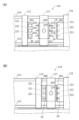
- FIG. (A) is a side view schematically showing a mold opening state of a mold device provided in a molding system according to an embodiment of the present invention
- (B) is a metal mold provided in the molding system according to an embodiment of the present invention.
- FIG. 4 is a side view schematically showing a clamping state of the mold device
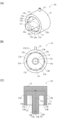
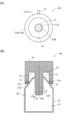
- 1(A) is a perspective view schematically showing an example of a suction portion of a molded article take-out machine provided in a molding system according to an embodiment of the present invention
- FIG. 1(B) is a front view schematically showing the suction portion; and (C) is a cross-sectional view schematically showing the adsorption portion.
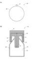
- (A) is a front view schematically showing a state in which the suction part shown in FIG. 3 holds a molded product
- (B) is a cross-sectional view schematically showing the suction part.
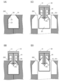
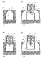
- (A) to (D) are diagrams schematically showing an example of a process in which the suction unit shown in FIG. 3 holds a molded product.
- A) is a front view schematically showing another example of the suction section of the molded article take-out machine provided in the molding system according to one embodiment of the present invention, and (B) is a cross section schematically showing the suction section.
- FIG. 4A to 4D are diagrams schematically showing another example of the process in which the suction part shown in FIG. 3 holds the hollow molded product
- FIG. 4A to 4D are diagrams schematically showing another example of the process in which the suction part shown in FIG. 3 holds the hollow molded product
- the present invention is applied to a molding system having a molding machine equipped with a mold device for performing injection molding of a preform and blow molding of a molded product in parallel, and a so-called traverse type molded product take-out device. Concrete.
- FIG. 1 is a schematic perspective view of a molding system according to this embodiment.
- 2(A) and 2(B) are side views schematically showing a mold device provided in the molding system.
- FIG. 2A corresponds to the mold open state
- FIG. 2B corresponds to the mold closed state.
- description of the support frame and the intermediate mold shown in FIGS. 2(A) and 2(B) is omitted.
- the molding system 100 includes a molding machine 110 and a molded article take-out machine 120 that unloads a molded article molded by the molding machine 110 .
- the mold device 114 provided in the molding machine 110 includes a cavity 211 functioning as an injection mold and a cavity 221 functioning as a blow mold.
- a bottomed parison, which is the preform 19 is injection molded in a cavity 211 functioning as an injection mold.
- the preform 19 is moved to a cavity 221 functioning as a blow mold, and a desired hollow molded product corresponding to the blow mold is blow-molded in the cavity 221 .
- the molding machine 110 has a known structure (for example, Japanese Unexamined Patent Application Publication No. 2018-167453), and is arranged with a stationary platen 111 and a movable platen 112 facing each other.
- the movable platen 112 is slidably supported by tie bars 113 arranged horizontally from the four corners of the fixed platen 111 .
- the movable platen 112 is driven by the mold clamping device 115 so as to move along the tie bars 113, and by this driving, a fixed mold 201 mounted on the fixed platen 111 and a movable mold 202 mounted on the movable platen 112 are provided. Mold clamping and mold opening of the mold device 114 are performed.
- the molded product takeout machine 120 includes a mount 121 , a traversing frame 122 , a first traveling body 123 , a drawing frame 124 , a second traveling body 125 , a head 126 and an elevating arm 127 .
- the traverse frame 122 extends in a direction in which the molded product produced by the molding machine 110 is carried out of the molding machine.
- the molded product take-out machine 120 is attached to the molding machine 110 by fixing the base end of the traverse frame 122 to the mounting base 121 installed on the stationary platen 111 .
- the first traveling body 123 is supported by the traverse frame 122 and moves forward and backward along the traverse frame 122 using a servomotor as a drive source.
- the drawing frame 124 has a base end fixed to the first traveling body 123 and is arranged to extend in the opening/closing direction of the mold device 114 .
- the second traveling body 125 is supported by the pull-out frame 124 and advances and retreats along the pull-out frame 124 using a servomotor as a drive source.
- Head 126 is supported by the lower end of lift arm 127 .
- the elevating arm 127 is arranged so as to extend in the vertical direction, and moves up and down in the vertical direction using a servomotor provided in the second traveling body 125 as a drive source. As the lift arm 127 moves vertically, the head 126 moves vertically.
- the head 126 includes one or more suction units 10 (described in detail below) arranged at positions corresponding to the molded product forming positions of the movable mold
- the mold device 114 provided in the molding machine 110 of this embodiment includes a fixed mold 201, a movable mold 202, and an intermediate mold 203.
- the intermediate mold 203 has a rectangular parallelepiped shape with two main surfaces 231 and 232 arranged to face the fixed mold 201 and the movable mold 202, respectively.
- the intermediate mold 203 is supported by a support frame 117 provided between the stationary platen 111 and the movable platen 112 .
- the support frame 117 is provided on the tie bars 113 so as to be movable in the movement direction of the movable platen 112 (the direction in which the tie bars 113 extend).
- the support frame 117 is driven independently of the movable platen 112 by a driving device (not shown).
- the intermediate mold 203 has a rotating shaft 235 arranged horizontally at an intermediate position in the vertical direction, perpendicular to the moving direction of the movable platen 112 , and the rotating shaft 235 is rotatably supported by the support frame 117 . It is By rotating the rotary shaft 235 using the servomotor of the support frame 117 as a drive source, one main surface 231 of the intermediate mold 203 faces the fixed mold 201 and the other main surface 232 is movable. A state in which one main surface 231 faces the movable mold 202 and a state in which the other main surface 232 faces the fixed mold 201 are realized.
- the surface of the stationary mold 201 facing the intermediate mold 203 has a plurality of elongated injection molding cavities having hemispherical bottoms. 211 is provided.
- a fixed mold 201 having a cavity 211 for injection molding functions as an injection mold as described later. For example, when an arrangement of two rows in the horizontal direction and three rows in the vertical direction is adopted, the fixed mold 201 is provided with a total of six injection molding cavities 211 .
- a rod 233 also serving as a blow pin is provided at a position corresponding to the injection molding cavity 211 when facing the fixed mold 201 .
- rods 234 also used as pro-pins are provided at positions corresponding to the injection molding cavities 211 in a state facing the fixed mold 201. It is
- blow molding cavities 221 are provided at each position.
- the movable mold 202 is provided with six blow molding cavities 221 .
- the inner surface of the blow molding cavity 221 has a shape corresponding to the outer surface of the above-described hollow molded article, and the movable mold 202 having the blow molding cavity 221 functions as a blow mold as described later.
- the injection molding cavity of the fixed mold 201 is closed.
- a rod 233 combined with a pro-pin on the main surface 231 of the intermediate mold 203 is inserted into the mold 211, and the rod 233 combined with a pro-pin and the cavity 211 for injection molding correspond to the shape of the preform (bottomed parison) described above.
- a preform cavity is constructed.
- a preform 19 is molded by injecting heat-melted resin into this preform cavity from an injection device 116 connected to a stationary platen 111 .
- the preform 19 is released from the injection molding cavity 211 while being held by the rod 233 that also serves as a pin (in a state that the rod 233 that also serves as a pin is covered). It is carried out (see FIG. 2(A)). Then, when the intermediate mold 203 is driven to rotate 180 degrees, the pro-pin and rod 234 holding the preform 19 is arranged in a state of facing each of the blow molding cavities 221 of the movable mold 202 .
- the preform is placed on the other main surface 232 of the intermediate mold 203 in the cavity 221 for blow molding of the movable mold 202 .
- a pro-pin combined rod 234 holding 19 is inserted.
- the rod 234 also used as a pro-pin is holding the preform 19 .
- the pro-pin combined rod 234 functions as a blow pin, and by blowing air (pressurized gas) from the pro-pin combined rod 234 into the preform 19, the outer surface corresponding to the shape of the cavity 221 is formed.
- a hollow molded product 20 having a shape is blow-molded. Also, at this time, the molded product is separated from the rod 234 also used as a pin by blowing air.
- the hollow molded product 20 blow-molded in the cavity 221 is indicated by a broken line for explanation.
- the injection molding of the preform 19 on the side of the fixed mold 201 of the intermediate mold 203 and the Blow molding of the desired hollow molded product 20 on the side of the movable mold 202 of the mold 203 is performed in parallel.
- the mold device 114 when the mold device 114 is in the mold open state, the fixed mold 201 and the movable mold 202 are separated, and the intermediate mold 203 is separated from the fixed mold 201 and the movable mold 202.
- a support frame 117 is arranged.
- the preform 19 is held by the pro-pin combined rod 233 on the main surface of the intermediate mold 203 on the fixed mold 201 side, and the intermediate mold 203 on the movable mold 202 side is held.
- the preform 19 held by the pro-pin combined rod 234 on the main surface is separated from the pro-pin combined use rod 234 as a result of the blow molding.
- the head 126 of the above molded product take-out machine 120 is placed in the space between the movable mold 202 and the intermediate mold 203. is inserted, and the hollow molded product 20 held in the cavity 221 of the movable mold 202 is carried out.
- the intermediate mold 203 is rotated 180 degrees, and the mold device 114 is brought into a clamping state, and injection molding of the preform 19 and blowing of the hollow molded product 20 are performed. molding will be performed again.
- FIG. 3(A) is a perspective view schematically showing an example of the suction part 10 provided in the head 126 of the molded product unloader 120 according to one embodiment of the present invention.
- FIG. 3B is a front view schematically showing the adsorption section 10.
- FIG. 3C is a cross-sectional view schematically showing the adsorption section 10.
- FIG. 4(A) is a front view schematically showing a state in which the suction part 10 shown in FIGS. 3(A) to 3(C) holds the hollow molded product 20.
- FIG. FIG. 3B is a cross-sectional view schematically showing a state in which the suction part 10 holds the hollow molded product 20.
- FIG. 3B is a cross-sectional view schematically showing a state in which the suction part 10 holds the hollow molded product 20.
- the hollow molded article 20 of the present embodiment is a bottomed cylindrical beverage container, and the opening (21) serving as a drinking mouth, the main body 23 made of a cylinder of the same diameter, and the opening 21 are smoothly arranged. and a shoulder 22 that connects to the . Since the opening 21 is configured to be sealed by heat sealing, the hollow molded product 20 does not have a flange portion (cap threaded portion) that is used for holding the molded product by the conventional molded product take-out machine described above. do not have.
- the opening 21 is formed during the injection molding of the above-described bottomed parison, which is the preform 19 , as a thick-walled portion whose entire periphery is thicker than the wall thickness of other portions of the hollow molded article 20 .
- each of the plurality of suction portions 10 provided in the head 126 of the molded product unloader 120 includes a cylindrical base plate 11, an insert portion 12 and a contact portion 13. has a structure in which is formed.
- the insert portion 12 has a cylindrical shape concentric with the center line of the base plate 11 and extending along the imaginary center line of the base plate 11 .
- the cross-sectional diameter of the insert portion 12 is smaller than the diameter of the opening 21 of the hollow molded product 20 to be conveyed.
- the opening 21 is an outlet for a blow pin that is inserted into the hollow molded product 20 in order to blow mold the hollow molded product 20 in the blow mold. inserted.
- the insert part 12 has a plurality of suction ports 12b for sucking the surrounding atmosphere at its tip.
- the insert portion 12 has one suction port 12b at the center of the tip 12a and four suction ports 12b opening at equal intervals on the outer peripheral surface near the tip 12a.
- Each suction port 12b is connected to an air flow path 12c arranged inside the insert portion 12, and the other end of the air flow path 12c is connected to a pipe connection portion 15 projecting from the outer peripheral surface of the base plate 11.
- a vacuum pump or a vacuum generator (ejector) is connected to the pipe connection portion 15 via an on-off valve or the like.
- the on/off of the suction at the plurality of suction ports 12b is switched.
- the non-suction state includes pressure increase.
- the contact portion 13 has a cylindrical shape extending along the imaginary center line of the base plate 11 so as to be concentric with the imaginary center line of the base plate 11. there is The axial length of the contact portion 13 is smaller than the axial length of the insert portion 12 .
- the outer diameter of the base plate 11 and the outer diameter of the contact portion 13 are the same, and the outer peripheral surface of the base plate 11 and the outer peripheral surface of the contact portion 13 form a series of outer peripheral surfaces. Configure.
- annular recess 14 is provided between the insert portion 12 and the contact portion 13 .
- the annular recess 14 accommodates the opening 21 of the hollow molded product 20 to be carried out.
- the annular contact surface 13b of the cylindrical contact portion 13 is positioned at a predetermined distance from the opening 21 of the hollow molded product 20. It abuts continuously on the outer peripheral surface of the distant hollow molded product 20 .
- the contact portion 13 contacts the outer peripheral surface formed by the shoulder portion 22 .
- the annular recess 14 constitutes a closed space 26 that communicates with the internal space 24 of the hollow molded product 20 .
- the closed space 26 does not need to be a completely sealed closed space, and may be any space in which the inside of the hollow molded product 20 can be decompressed by suction through the suction port 12b of the insert portion 12.
- FIG. That is, if the inside of the hollow molded product 20 can be decompressed by suction through the suction port 12b of the insert portion 12, for example, a gap is formed between the outer peripheral surface of the hollow molded product 20 and the contact surface 13b of the contact portion 13.
- a configuration in which a through hole, an opening, or the like exists in the cylindrical surface forming the contact surface 13b of the contact portion 13 may be employed.
- an inclined surface aligned with the shoulder portion 22 of the hollow molded product 20 constitutes the contact surface 13b.
- the contact surface 13b which is an inclined surface, is provided with a predetermined width at the inner peripheral edge of the contact portion 13. As shown in FIG. As a result, the contact area of the contact surface 13b formed by the outer peripheral surfaces of the contact portion 13 and the shoulder portion 22 and the inclined surface can be increased, and the closed space 26 can be easily configured.
- the contact portion 13 has an additional suction port 13c for sucking the outer peripheral surface of the hollow molded product 20 on the inclined surface that is the contact surface 13b with the hollow molded product 20.
- additional suction ports 13c are arranged at regular intervals on the inclined surface that is the contact surface 13b.
- Each suction port 13c is connected to an air flow path 13d arranged inside the contact portion 13, and the other end of the air flow path 13d is connected to the air flow path 12c. Therefore, the ON/OFF state of suction at the additional suction port 13c of the contact portion 13 (suction state and non-suction state) is switched in synchronism with the ON/OFF state of suction at the suction port 12b of the insert portion 12. .
- FIGS. 5A to 5D are diagrams schematically showing the process of holding the hollow molded product 20 by the suction part 10 described above.
- FIG. 5(A) shows that the preform 19 [FIG. 2(A)] is formed into a shape corresponding to the cavity 221 of the movable mold 202, which is a blow mold, by blowing air, and then the blowing air is ejected.
- FIG. 4 is a diagram showing a state in which a rod 233 or 234 is pulled out from an opening 21 of a hollow molded product 20, which is a blow pin extraction port;
- the movable mold 202 is divided into two along a vertical plane including the virtual center line of the main body 23 of the hollow molded product 20 . Further, when the movable mold 202 is in the split-open state, the hollow molded product 20 can be carried out in the vertical direction or in the direction in which the imaginary center line of the main body 23 extends without interfering with the movable mold 202 . In addition, in the cavity 221 of the movable mold 202 in the split mold closed state, at a position corresponding to the opening 21 of the hollow molded product 20, a concave portion matching the above-described thick portion constituting the opening 21 is provided.
- the preform 19 when the preform 19 is placed in the cavity 221 of the movable mold 202, the entire preform 19 is accommodated in the movable mold 202, and the preform 19 (and the hollow molded product 20) is outside the movable mold 202. It has a configuration that does not have a portion that protrudes into the body.
- the suction part 10 is arranged in a state in which the opening 21 and the insert part 12 face each other, and as shown in FIG.
- the insert portion 12 is inserted into the .
- the hollow molded product 20 is arranged so that the imaginary center line of the main body 23 is horizontal, so the insert portion 12 is inserted into the hollow molded product 20 by moving in the horizontal direction. be.
- the tip 12a of the insert portion 12 is arranged in the vicinity of the switching portion between the shoulder portion 22 and the body portion 23 in the direction in which the virtual center line of the hollow molded product 20 extends.
- the length of the insert portion 12 in the imaginary centerline direction is designed so as to be in a state where
- the plurality of suction ports 12b of the insert portion 12 and the plurality of additional suction ports 13c of the contact portion 13 are switched from the non-suction state to the suction state.
- the surrounding atmosphere is sucked through the plurality of suction ports 12 b of the insert portion 12 , and an air current flowing from the outside to the inside of the hollow molded product 20 through the openings 21 is generated.
- the movable mold 202 is in the split open state. Due to the opening of the split mold, the hollow molded product 20 moves to the base end side of the insert portion 12 (to the base plate 11 side) due to the air current flowing from the opening 21 . Due to the movement of the hollow molded product 20, the opening 21 of the hollow molded product 20 is accommodated in the recess 14, and the shoulder 22 of the hollow molded product 20 comes into contact with the contact portion 13, as shown in FIG. 5(D). It abuts on the inclined surface that is the contact surface 13b. As a result, the recess 14 and the internal space of the hollow molded product 20 form a series of hollow spaces.
- the airflow caused by the suction by the suction port 13c of the contact portion 13 promotes the movement of the opening 21 to the concave portion 14, and the suction by the suction port 13c causes the shoulder 22 to hit.
- the state of contact with the contact surface 13b is maintained. Even in this state, since the ambient atmosphere continues to be sucked from the suction port 12b of the insert portion 12, the shoulder portion 22 of the hollow molded product 20 is pressed against the contact surface 13b. is reliably supported by the contact portion 13 .
- the hollow molded product 20 can be unloaded from the movable mold 202 by moving the sucking part 10 holding the hollow molded product 20 in this manner vertically upward by the molded product take-out device 120 .
- the molding system 100 molded article take-out machine 120
- the adsorption unit 10 of the present embodiment even if the hollow molded article 20 does not have a portion protruding from the movable mold 202, the hollow molded article
- the hollow molded product 20 can be carried out from the movable mold 202 without touching the opening 21 or the inner surface of the hollow molded product 20 . Therefore, even for hollow molded products that have been made thinner and lighter, or that have been changed to biodegradable resin, it is possible to remove the hollow molded product from the blow mold while avoiding damage to the hollow molded product and contamination of the opening. can be carried out.
- the contact surface 13b forming the inclined surface has the additional suction port 13c, but it is not essential to have the additional suction port 13c.
- the surrounding atmosphere is continuously sucked through the plurality of suction ports 12b, so that the shoulder 22 of the hollow molded product 20 is hit. It is pressed against the contact surface 13 b forming the inclined surface of the contact portion 13 . Therefore, the shoulder portion 22 of the hollow molded product 20 is supported by the contact portion 13 even in a configuration without the additional suction port 13c.
- the suction port 12b and the suction port 13c are synchronously turned on and off at the same time. It is also possible to employ a configuration in which a vacuum system for switching on and off of suction at 13c is provided independently.
- a configuration has been described in which a vacuum system that applies a suction force to the suction port 12b and the additional suction port 13c is connected to the pipe connection portion 15.
- an ejector is provided on the base plate 11 and the ejector It is also possible to employ a configuration in which the inside of the air flow path 12c connected to the intake port of the ejector is decompressed by supplying pressurized gas using a compressor or the like.
- FIG. 6A is a front view schematically showing the adsorption section 40.
- FIG. FIG. 6B is a cross-sectional view schematically showing the adsorption section 40.
- FIG. 6(A) and 6(B) differ only in the configuration of the suction portion 10 and the contact portion 13 described with reference to FIGS. 3(A) to 3(C). Since other configurations are the same, the same elements are denoted by the same reference numerals as in FIGS. 3(A) to 3(C).
- the suction unit 40 is used in the molding system 100 in place of the suction unit 10 described above.
- the suction section 40 differs from the suction section 10 described above in that an elastic body 13e is provided at a predetermined length from the tip 13a of the contact section 13 having a contact surface that contacts the hollow molded article 20.
- the material of the elastic body 13e is not particularly limited, for example, rubber materials such as silicone rubber, nitrile rubber, and urethane rubber can be used.
- the elastic body 13e since the elastic body 13e constitutes the entire tip 13a of the contact section 13, the contact surface 13b formed by the inclined surface provided in the adsorption section 10, the additional suction port 13c, and the air flow path are provided. 13d is also different.
- the shape of the elastic body 13e that serves as the contact surface is aligned with the outer peripheral surface of the shoulder portion 22. transform.
- the contact area between the shoulder portion 22 of the hollow molded product 20 and the elastic body 13e that forms the contact surface of the contact portion 13 increases, so that the shoulder portion 22 of the hollow molded product 20 is made more elastic by the contact portion 13. can definitely support.
- the surface shape of the elastic body 13e can adopt any other shape such as a curved surface.
- the contact surface 13b made of the inclined surface, the additional suction port 13c, and the air flow path 13d are not provided. It is also possible to provide an abutment surface 13b formed of an inclined surface, an additional suction port 13c, and an air flow path 13d.
- only the tip portion of the contact portion 13 is made of an elastic material, but the entire contact portion 13 and the suction portion 40 may be made of an elastic material.
- FIGS. 7(A) to 7(D) another procedure for holding the hollow molded product 20 by the suction part 10 described above will be described.
- the suction port 12b of the insert portion 12 of the adsorption unit 10 must function as a jet port for jetting the pressurized gas. Therefore, in this example, a vacuum system that applies a suction force to the suction port 12b and a gas supply system that supplies pressurized gas to the suction port 12b are switchably connected to the pipe connection portion 15 of the adsorption unit 10. .
- Such a configuration can be realized, for example, by using a vacuum pump for the vacuum system, using a compressor for the gas supply system, and connecting each system and the pipe connection part 15 via a three-way valve or the like. .
- a simpler configuration an ejector and a compressor are used, and the state in which the vacuum port of the ejector is connected to the pipe connection portion 15 and the state in which the output port of the compressor is connected to the pipe connection portion 15 are controlled by the solenoid valve.
- FIG. 7A shows that after the preform is formed into a shape corresponding to the cavity 241 of the movable mold 204 by blown air, the blow pin (above-mentioned blow pin combined rod 233 or 234) ejecting the blown air is ejected from the blow pin outlet. It is a figure which shows the state extracted from the opening part 21 of the hollow molded product 20 which is.
- the movable mold 204 is used in the molding system 100 in place of the movable mold 202 described above.
- the movable mold 204 differs from the movable mold 202 described above in that the mold portion 242 corresponding to the bottom of the hollow molded product 20 moves when the mold is split open. Not configured. Similar to the movable mold 202, the movable mold 204 other than the mold part 242 is divided into two along the vertical plane including the virtual center line of the main body 23 of the hollow molded product 20, so that the split mold can be opened and closed. ing. As with the movable mold 202, when the split mold is open, the hollow molded product 20 can be carried out in the vertical direction or in the direction along which the imaginary center line of the main body 23 extends without interfering with the movable mold 204. .
- the suction part 10 is arranged in a state where the opening 21 and the insert part 12 face each other, and as shown in FIG.
- the insert portion 12 is inserted into the .
- the state is switched to a state in which the pressurized gas is jetted from the suction port 12b of the insert portion 12 and the additional suction port 13c of the contact portion 13.
- FIG. That is, when the suction port 13 c is switched to the injection port, the hollow molded product 20 is pressed against the movable mold 204 .
- the suction portion 10 is moved in the direction of the hollow molded product 20, so that the contact formed by the inclined surface is changed.
- the surface 13 b may be brought closer to the shoulder portion 22 , and the contact surface 13 b formed of an inclined surface may be brought into contact with the shoulder portion 22 .
- the hollow molded product 20 can be unloaded from the movable mold 204 by moving the sucking part 10 holding the hollow molded product 20 in this manner vertically upward by the molded product take-out device 120 . According to this procedure, as in the procedure described above, even if the hollow molded product 20 does not have a portion protruding from the movable mold 204, the movable mold 204 can be removed without touching the opening 21 or the inner surface of the hollow molded product 20. The hollow molded product 20 can be carried out from the . Therefore, even if the molded product is made thinner and lighter, or the material is changed to biodegradable resin, the molded product should be carried out from the blow mold in a state where damage to the molded product and contamination of the opening are avoided. can be done.
- the additional suction port 13c can also be used as a jet port for jetting pressurized gas. Therefore, for example, when the taken-out hollow molded product 20 is removed from the molded product take-out machine 120, the pressurized gas is ejected from the suction port 13c, which is the ejection port of the contact portion 13, so that the hollow molded product 20 can be removed more reliably. can also be removed.
- the suction port 12b in the insert portion 12 also serves as a jet port for jetting pressurized gas, but the insert portion 12 is provided independently of the suction port 12b. It is also possible to employ a configuration that includes a spout. Similarly, in the contact portion 13, the suction port 13c is configured to serve as an ejection port for ejecting the pressurized gas. is also possible.
- the contact portion 13 has both the suction port and the ejection port, and it is possible to employ a configuration that does not include either or both of them.
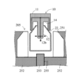
- FIGS. 8(A) to 8(D) still another procedure for holding the hollow molded product 20 by the suction part 10 described above will be described with reference to FIGS. 8(A) to 8(D).
- a mold device for blow-molding the molded product holds the hollow molded product 20 in the split open state.
- FIG. 8A shows that after the preform is formed into a shape corresponding to the cavity 251 of the movable mold 205 by blowing air, the blow pin (above-mentioned blow pin combined rod 233 or 234) ejecting the blow air is ejected from the blow pin outlet. It is a figure which shows the state extracted from the opening part 21 of the hollow molded product 20 which is.
- the movable mold 205 is used in the molding system 100 in place of the movable mold 202 described above.
- a movable mold 205 that constitutes a part of the mold apparatus 114 is a mold on the bottom side of the hollow molded product 20, similar to the movable mold 204 described above.
- the parts are not divided by a vertical plane including the imaginary centerline of the body portion 23 of the hollow molded product 20 .
- the mold portion on the bottom side of the hollow molded product 20 is composed of a plurality of mold members 252 and 253 .
- a first mold member 252 forming a cavity portion contacting the periphery of the bottom of the hollow molded product 20 and a second mold member 253 forming a cavity portion contacting the central portion of the bottom of the hollow molded product 20 It is configured.
- the second mold member 253 is a cylindrical member concentric with the imaginary center line of the body portion 23 of the hollow molded product 20, and is configured to be axially advanced and retractable by a drive source such as a hydraulic cylinder (not shown).
- the movable mold 205 other than the first mold member 252 and the second mold member 253 is divided into two along the vertical plane including the virtual center line of the body portion 23 of the hollow molded product 20, similarly to the movable mold 202.
- the hollow molded product 20 can be carried out in the vertical direction or in the direction along which the imaginary center line of the main body 23 extends without interfering with the movable mold 204. .
- the first mold member 252 has a first bottom wall surface portion 251Aa of the bottom wall surface 251A of the cavity 251 as a surface constituting the cavity. 252, and has a second bottom wall surface portion 251Ab of the bottom wall surface 251A of the cavity 251 as a component surface of the cavity.
- the first bottom wall surface portion 251Aa of the first mold member 252 and the second bottom wall surface portion 251Ab of the second mold member 253 constitute the bottom wall surface 251A of the cavity 251 in the closed state.
- the second mold member 253 is moved away from the hollow molded product 20, so that the first mold member 252 faces the cavity 251.
- the surface forming the cavity of the second mold member 253 is arranged differently from the split mold closed state (closed mold state).
- a recess 254 having the first mold member 252 as a wall surface is formed. That is, after the hollow molded product is molded, the second mold member 253 is moved so as to form a recess 254 between the second bottom wall portion 251Ab of the second mold member 253 and the outer surface of the hollow molded product. Moving.
- the suction port 255a is connected to an air channel 255 provided inside the first mold member 252, and the other end of the air channel 255 is connected to a vacuum pump or a vacuum generator via an on-off valve or the like. be.
- the suction port 255a is switched between ON and OFF (suction state and non-suction state).
- the suction port 255a also functions as an ejection port for ejecting pressurized gas. Therefore, the other end of the air flow path 255 is switchably connected to a vacuum system that applies a suction force to the suction port 255a and a gas supply system that supplies pressurized gas to the suction port 255a.
- the suction port 255a When the suction port 255a is exposed in the recess 254 by the movement of the second mold member 253, the suction port 255a is switched to the suction state. As a result, the hollow molded product 20 is sucked and held with the peripheral portion of the bottom surface in contact with the first mold member 252 . That is, the mold apparatus 114 can be brought into a suction holding state in which the hollow molded product is held by suction on the first bottom wall surface portion 251Aa of the first mold member 252 by reducing the pressure inside the recess 254 .
- the hollow molded product is held by suction on the mold device, so that the molded product is held by the mold device even when the mold device is in the split-open state in order to carry out the molded product. Therefore, the outer peripheral surface of the hollow molded product can be reliably brought into contact with the contact portion 13, and the hollow molded product can be carried out more easily. Therefore, the suction unit 10 is arranged with the opening 21 and the insert 12 facing each other, and the insert 12 is inserted into the hollow molded product 20 through the opening 21 as shown in FIG. 8(B).
- the suction port 12b of the insert portion 12 and the suction port 13c of the contact portion 13 are switched to the suction state.
- the surrounding atmosphere is sucked through the suction port 12 b of the insert portion 12 , and an air current flowing from the outside to the inside of the hollow molded product 20 through the opening 21 is generated.
- the inside of the recess 254 is brought into a non-depressurized state so that the hollow molded product is not held by suction on the first bottom wall surface portion 251Aa of the first mold member 252.
- the suction port 255a exposed in the recess 254 is switched to a state in which the pressurized gas is ejected.
- the bottom portion of the hollow molded product 20 is released from being held by suction, and the pressurized gas ejected from the suction port 255 a and the airflow flowing in from the opening 21 cause the hollow molded product 20 to move away from the insert portion 12 . Move proximally. Due to the movement of the hollow molded product 20, as shown in FIG. It abuts on the abutment surface 13b which is an inclined surface. As a result, the shoulder portion 22 of the hollow molded product 20 is reliably supported by the contact portion 13 as in the case shown in FIG. 5(D).
- the suction unit 10 is moved in the direction of the hollow molded product 20.
- the contact surface 13b may be brought closer to the shoulder portion 22, and the contact surface 13b may be brought into contact with the outer peripheral surface forming the shoulder portion 22. As shown in FIG.
- the hollow molded product 20 can be unloaded from the movable mold 204 by moving the sucking part 10 holding the hollow molded product 20 in this manner vertically upward by the molded product take-out device 120 . According to this procedure, as in the procedure described above, even if the hollow molded product 20 does not have a portion protruding from the movable mold 204, the movable mold 204 can be removed without touching the opening 21 or the inner surface of the hollow molded product 20. The hollow molded product 20 can be carried out from the . Therefore, even for hollow molded products that have been made thinner and lighter, or that have been changed to biodegradable resin, the molded product can be removed from the blow mold while avoiding damage to the molded product and contamination of the opening. be able to.
- the suction port 255a is configured to serve as a jet port for jetting the pressurized gas. Configurations can also be employed.
- a second mold member 253 presses the hollow molded article 20 as shown in FIG. You may provide so that it can move in the direction which carries out. Further, it is not essential to provide a configuration for assisting the removal of the sucked and held hollow molded product 20, and it is also possible to adopt a configuration that simply switches the suction port 255a to the non-suction state.
- the insert part 12 may be inserted into the hollow molded product 20 after the split mold is opened.
- the second mold member 253 is driven. Just do it. Also, it is not essential to provide the suction port 255a.
- the suction force may be used to attract and hold the molded product.
- the part of the molded product to be held by suction is not limited to the bottom part, and other parts may be held by suction.
- the number, shape, and arrangement positions of the suction ports and the number, shape, and arrangement positions of the ejection ports in the suction section described above are merely examples, and can be changed as appropriate.
- the numbers, shapes, and arrangement positions of the recesses and projections in the mold apparatus described above are merely examples, and can be changed as appropriate.
- the physical shape and material of each element described above can be arbitrarily changed within the scope of the effects of the present invention.
- a molded product that does not have a part protruding from the blow mold can be carried out from the blow mold without touching the opening or the inner surface. It is useful as a take-out machine, a molded product take-out method, a mold device, a molding machine, and a drive method for the mold device.
- Reference Signs List 10 40 suction portion 11 base plate 12 insert portion 12b suction port (jet port) 12c air flow path 13 contact portion 13b inclined surface (contact surface with molded product) 13c suction port (spout) 13d air flow path 13e elastic body 14 concave portion 15 pipe connecting portion 20 hollow molded product 21 opening (blow pin outlet) 22 shoulder (peripheral surface) 23 Body Part 100 Molding System 110 Molding Machine 114 Mold Device 120 Molded Product Extractor 202, 204, 205 Movable mold (blow mold) 221, 241, 251 blow molding cavity 252 first mold member 253 second mold member 254 recess 255a suction port (jet port)
Landscapes
- Engineering & Computer Science (AREA)
- Manufacturing & Machinery (AREA)
- Mechanical Engineering (AREA)
- Moulds For Moulding Plastics Or The Like (AREA)
- Blow-Moulding Or Thermoforming Of Plastics Or The Like (AREA)
Priority Applications (4)
| Application Number | Priority Date | Filing Date | Title |
|---|---|---|---|
| EP22876448.6A EP4410514A4 (en) | 2021-09-29 | 2022-09-29 | MOLDING SYSTEM, MOLDED ARTICLE EXTRACTION MACHINE, MOLDING DEVICE AND METHOD FOR MANUFACTURING A HOLLOW MOLDED ARTICLE |
| CN202280065519.0A CN118043190A (zh) | 2021-09-29 | 2022-09-29 | 成形系统、成形件取出机、模具装置以及制造中空成形件的方法 |
| JP2023551846A JPWO2023054584A1 (enExample) | 2021-09-29 | 2022-09-29 | |
| US18/695,217 US20240399644A1 (en) | 2021-09-29 | 2022-09-29 | Molding system, apparatus for taking out molded product, mold equipment, and method for manufacturing hollow molded product |
Applications Claiming Priority (2)
| Application Number | Priority Date | Filing Date | Title |
|---|---|---|---|
| JP2021159205 | 2021-09-29 | ||
| JP2021-159205 | 2021-09-29 |
Publications (1)
| Publication Number | Publication Date |
|---|---|
| WO2023054584A1 true WO2023054584A1 (ja) | 2023-04-06 |
Family
ID=85782886
Family Applications (1)
| Application Number | Title | Priority Date | Filing Date |
|---|---|---|---|
| PCT/JP2022/036438 Ceased WO2023054584A1 (ja) | 2021-09-29 | 2022-09-29 | 成形システム、成形品取出機、金型装置及び中空成形品を製造する方法 |
Country Status (5)
| Country | Link |
|---|---|
| US (1) | US20240399644A1 (enExample) |
| EP (1) | EP4410514A4 (enExample) |
| JP (1) | JPWO2023054584A1 (enExample) |
| CN (1) | CN118043190A (enExample) |
| WO (1) | WO2023054584A1 (enExample) |
Citations (5)
| Publication number | Priority date | Publication date | Assignee | Title |
|---|---|---|---|---|
| JP2006035672A (ja) | 2004-07-28 | 2006-02-09 | Sumitomo Heavy Ind Ltd | 吹込成形方法 |
| JP2006315266A (ja) * | 2005-05-12 | 2006-11-24 | Toppan Printing Co Ltd | 二軸延伸ブロー成形方法 |
| JP2007069241A (ja) | 2005-09-07 | 2007-03-22 | Toyo Seikan Kaisha Ltd | ロータリー式ブロー成形装置及びロータリー式ブロー成形方法 |
| JP2018161858A (ja) * | 2017-03-27 | 2018-10-18 | 株式会社吉野工業所 | 容器製造方法 |
| JP2018167453A (ja) | 2017-03-29 | 2018-11-01 | 住友重機械工業株式会社 | 射出成形機 |
Family Cites Families (3)
| Publication number | Priority date | Publication date | Assignee | Title |
|---|---|---|---|---|
| US3851030A (en) * | 1971-12-23 | 1974-11-26 | E Valvi | Method for the production of composite containers |
| BE795708A (fr) * | 1972-02-24 | 1973-08-21 | Franc De Comp | Moules et procede pour le soufflage de corps creux en matiere plastique |
| US12397486B2 (en) * | 2019-04-08 | 2025-08-26 | Nissei Asb Machine Co., Ltd. | Cooling mold, and apparatus and method for manufacturing resin molded article |
-
2022
- 2022-09-29 CN CN202280065519.0A patent/CN118043190A/zh active Pending
- 2022-09-29 EP EP22876448.6A patent/EP4410514A4/en active Pending
- 2022-09-29 WO PCT/JP2022/036438 patent/WO2023054584A1/ja not_active Ceased
- 2022-09-29 JP JP2023551846A patent/JPWO2023054584A1/ja active Pending
- 2022-09-29 US US18/695,217 patent/US20240399644A1/en active Pending
Patent Citations (5)
| Publication number | Priority date | Publication date | Assignee | Title |
|---|---|---|---|---|
| JP2006035672A (ja) | 2004-07-28 | 2006-02-09 | Sumitomo Heavy Ind Ltd | 吹込成形方法 |
| JP2006315266A (ja) * | 2005-05-12 | 2006-11-24 | Toppan Printing Co Ltd | 二軸延伸ブロー成形方法 |
| JP2007069241A (ja) | 2005-09-07 | 2007-03-22 | Toyo Seikan Kaisha Ltd | ロータリー式ブロー成形装置及びロータリー式ブロー成形方法 |
| JP2018161858A (ja) * | 2017-03-27 | 2018-10-18 | 株式会社吉野工業所 | 容器製造方法 |
| JP2018167453A (ja) | 2017-03-29 | 2018-11-01 | 住友重機械工業株式会社 | 射出成形機 |
Non-Patent Citations (1)
| Title |
|---|
| See also references of EP4410514A4 |
Also Published As
| Publication number | Publication date |
|---|---|
| US20240399644A1 (en) | 2024-12-05 |
| CN118043190A (zh) | 2024-05-14 |
| EP4410514A1 (en) | 2024-08-07 |
| JPWO2023054584A1 (enExample) | 2023-04-06 |
| EP4410514A4 (en) | 2025-09-24 |
Similar Documents
| Publication | Publication Date | Title |
|---|---|---|
| TWI232161B (en) | Platen mounted post mold cooling apparatus and method | |
| JP2509803B2 (ja) | 成形品の搬送装置 | |
| JP6124920B2 (ja) | 成形装置のシールシステム | |
| EP1029789A2 (en) | Contact lens transfer and material removal system | |
| JPH0316710A (ja) | 成形品の成形装置 | |
| JP2003201129A (ja) | 吹込成形ヘッド機構 | |
| WO2016147531A1 (ja) | ブロー成形装置 | |
| JP4308773B2 (ja) | 取り出し装置用吸引スリーブ延長部 | |
| US20170305060A1 (en) | Blow molding machine with molds moved mechanically and without the aid of electrical, hydraulic or pneumatic devices | |
| WO2023054584A1 (ja) | 成形システム、成形品取出機、金型装置及び中空成形品を製造する方法 | |
| KR101164446B1 (ko) | 사출성형기용 프리폼 취출 냉각장치 | |
| JP2016168801A (ja) | ブロー成形装置 | |
| JP2003206141A (ja) | 搬出機構 | |
| JP2003201131A (ja) | 搬出機構 | |
| JPWO2023054584A5 (enExample) | ||
| JP2003201133A (ja) | I.s.成形機用のデッドプレート組立体 | |
| KR102225042B1 (ko) | 사출 금형장치 | |
| US20070248713A1 (en) | Vertical alternation type bottle blower | |
| JP4209304B2 (ja) | 広口容器のラベルインモールド成形方法およびラベル吸着保持用の疑似コア | |
| WO2008011702A1 (en) | Pneumatic structure | |
| EP1839841A1 (en) | Vertical alternation blow moulding apparatus | |
| CN219947225U (zh) | 一种阀门装置及吹塑系统 | |
| KR100393320B1 (ko) | 라벨필름의 인몰드성형방법 및 그 장치 | |
| ITMI982470A1 (it) | Dispositivo e metodo di raffreddamento ed estrazione di corpi cavistampati ad iniezione | |
| EP1948416A1 (en) | System and method for transferring and cooling molded hollow plastic articles |
Legal Events
| Date | Code | Title | Description |
|---|---|---|---|
| 121 | Ep: the epo has been informed by wipo that ep was designated in this application |
Ref document number: 22876448 Country of ref document: EP Kind code of ref document: A1 |
|
| WWE | Wipo information: entry into national phase |
Ref document number: 2023551846 Country of ref document: JP |
|
| WWE | Wipo information: entry into national phase |
Ref document number: 18695217 Country of ref document: US |
|
| WWE | Wipo information: entry into national phase |
Ref document number: 202280065519.0 Country of ref document: CN |
|
| NENP | Non-entry into the national phase |
Ref country code: DE |
|
| ENP | Entry into the national phase |
Ref document number: 2022876448 Country of ref document: EP Effective date: 20240429 |