WO2023054445A1 - 電池パック及び電気機器 - Google Patents
電池パック及び電気機器 Download PDFInfo
- Publication number
- WO2023054445A1 WO2023054445A1 PCT/JP2022/036104 JP2022036104W WO2023054445A1 WO 2023054445 A1 WO2023054445 A1 WO 2023054445A1 JP 2022036104 W JP2022036104 W JP 2022036104W WO 2023054445 A1 WO2023054445 A1 WO 2023054445A1
- Authority
- WO
- WIPO (PCT)
- Prior art keywords
- battery pack
- main body
- control unit
- information
- output
- Prior art date
- Legal status (The legal status is an assumption and is not a legal conclusion. Google has not performed a legal analysis and makes no representation as to the accuracy of the status listed.)
- Ceased
Links
Images











Classifications
-
- H—ELECTRICITY
- H01—ELECTRIC ELEMENTS
- H01M—PROCESSES OR MEANS, e.g. BATTERIES, FOR THE DIRECT CONVERSION OF CHEMICAL ENERGY INTO ELECTRICAL ENERGY
- H01M10/00—Secondary cells; Manufacture thereof
- H01M10/42—Methods or arrangements for servicing or maintenance of secondary cells or secondary half-cells
- H01M10/425—Structural combination with electronic components, e.g. electronic circuits integrated to the outside of the casing
-
- H—ELECTRICITY
- H01—ELECTRIC ELEMENTS
- H01M—PROCESSES OR MEANS, e.g. BATTERIES, FOR THE DIRECT CONVERSION OF CHEMICAL ENERGY INTO ELECTRICAL ENERGY
- H01M10/00—Secondary cells; Manufacture thereof
- H01M10/42—Methods or arrangements for servicing or maintenance of secondary cells or secondary half-cells
- H01M10/48—Accumulators combined with arrangements for measuring, testing or indicating the condition of cells, e.g. the level or density of the electrolyte
-
- B—PERFORMING OPERATIONS; TRANSPORTING
- B25—HAND TOOLS; PORTABLE POWER-DRIVEN TOOLS; MANIPULATORS
- B25F—COMBINATION OR MULTI-PURPOSE TOOLS NOT OTHERWISE PROVIDED FOR; DETAILS OR COMPONENTS OF PORTABLE POWER-DRIVEN TOOLS NOT PARTICULARLY RELATED TO THE OPERATIONS PERFORMED AND NOT OTHERWISE PROVIDED FOR
- B25F5/00—Details or components of portable power-driven tools not particularly related to the operations performed and not otherwise provided for
-
- B—PERFORMING OPERATIONS; TRANSPORTING
- B25—HAND TOOLS; PORTABLE POWER-DRIVEN TOOLS; MANIPULATORS
- B25F—COMBINATION OR MULTI-PURPOSE TOOLS NOT OTHERWISE PROVIDED FOR; DETAILS OR COMPONENTS OF PORTABLE POWER-DRIVEN TOOLS NOT PARTICULARLY RELATED TO THE OPERATIONS PERFORMED AND NOT OTHERWISE PROVIDED FOR
- B25F5/00—Details or components of portable power-driven tools not particularly related to the operations performed and not otherwise provided for
- B25F5/02—Construction of casings, bodies or handles
-
- H—ELECTRICITY
- H01—ELECTRIC ELEMENTS
- H01M—PROCESSES OR MEANS, e.g. BATTERIES, FOR THE DIRECT CONVERSION OF CHEMICAL ENERGY INTO ELECTRICAL ENERGY
- H01M10/00—Secondary cells; Manufacture thereof
- H01M10/42—Methods or arrangements for servicing or maintenance of secondary cells or secondary half-cells
- H01M10/48—Accumulators combined with arrangements for measuring, testing or indicating the condition of cells, e.g. the level or density of the electrolyte
- H01M10/482—Accumulators combined with arrangements for measuring, testing or indicating the condition of cells, e.g. the level or density of the electrolyte for several batteries or cells simultaneously or sequentially
-
- H—ELECTRICITY
- H01—ELECTRIC ELEMENTS
- H01M—PROCESSES OR MEANS, e.g. BATTERIES, FOR THE DIRECT CONVERSION OF CHEMICAL ENERGY INTO ELECTRICAL ENERGY
- H01M50/00—Constructional details or processes of manufacture of the non-active parts of electrochemical cells other than fuel cells, e.g. hybrid cells
- H01M50/20—Mountings; Secondary casings or frames; Racks, modules or packs; Suspension devices; Shock absorbers; Transport or carrying devices; Holders
- H01M50/204—Racks, modules or packs for multiple batteries or multiple cells
-
- H—ELECTRICITY
- H01—ELECTRIC ELEMENTS
- H01M—PROCESSES OR MEANS, e.g. BATTERIES, FOR THE DIRECT CONVERSION OF CHEMICAL ENERGY INTO ELECTRICAL ENERGY
- H01M50/00—Constructional details or processes of manufacture of the non-active parts of electrochemical cells other than fuel cells, e.g. hybrid cells
- H01M50/20—Mountings; Secondary casings or frames; Racks, modules or packs; Suspension devices; Shock absorbers; Transport or carrying devices; Holders
- H01M50/204—Racks, modules or packs for multiple batteries or multiple cells
- H01M50/207—Racks, modules or packs for multiple batteries or multiple cells characterised by their shape
- H01M50/213—Racks, modules or packs for multiple batteries or multiple cells characterised by their shape adapted for cells having curved cross-section, e.g. round or elliptic
-
- H—ELECTRICITY
- H01—ELECTRIC ELEMENTS
- H01M—PROCESSES OR MEANS, e.g. BATTERIES, FOR THE DIRECT CONVERSION OF CHEMICAL ENERGY INTO ELECTRICAL ENERGY
- H01M50/00—Constructional details or processes of manufacture of the non-active parts of electrochemical cells other than fuel cells, e.g. hybrid cells
- H01M50/20—Mountings; Secondary casings or frames; Racks, modules or packs; Suspension devices; Shock absorbers; Transport or carrying devices; Holders
- H01M50/247—Mountings; Secondary casings or frames; Racks, modules or packs; Suspension devices; Shock absorbers; Transport or carrying devices; Holders specially adapted for portable devices, e.g. mobile phones, computers, hand tools or pacemakers
-
- H—ELECTRICITY
- H01—ELECTRIC ELEMENTS
- H01M—PROCESSES OR MEANS, e.g. BATTERIES, FOR THE DIRECT CONVERSION OF CHEMICAL ENERGY INTO ELECTRICAL ENERGY
- H01M50/00—Constructional details or processes of manufacture of the non-active parts of electrochemical cells other than fuel cells, e.g. hybrid cells
- H01M50/20—Mountings; Secondary casings or frames; Racks, modules or packs; Suspension devices; Shock absorbers; Transport or carrying devices; Holders
- H01M50/284—Mountings; Secondary casings or frames; Racks, modules or packs; Suspension devices; Shock absorbers; Transport or carrying devices; Holders with incorporated circuit boards, e.g. printed circuit boards [PCB]
-
- H—ELECTRICITY
- H01—ELECTRIC ELEMENTS
- H01M—PROCESSES OR MEANS, e.g. BATTERIES, FOR THE DIRECT CONVERSION OF CHEMICAL ENERGY INTO ELECTRICAL ENERGY
- H01M50/00—Constructional details or processes of manufacture of the non-active parts of electrochemical cells other than fuel cells, e.g. hybrid cells
- H01M50/20—Mountings; Secondary casings or frames; Racks, modules or packs; Suspension devices; Shock absorbers; Transport or carrying devices; Holders
- H01M50/296—Mountings; Secondary casings or frames; Racks, modules or packs; Suspension devices; Shock absorbers; Transport or carrying devices; Holders characterised by terminals of battery packs
-
- B—PERFORMING OPERATIONS; TRANSPORTING
- B25—HAND TOOLS; PORTABLE POWER-DRIVEN TOOLS; MANIPULATORS
- B25B—TOOLS OR BENCH DEVICES NOT OTHERWISE PROVIDED FOR, FOR FASTENING, CONNECTING, DISENGAGING, OR HOLDING
- B25B21/00—Portable power-driven screw or nut setting or loosening tools; Attachments for drilling apparatus serving the same purpose
- B25B21/02—Portable power-driven screw or nut setting or loosening tools; Attachments for drilling apparatus serving the same purpose with means for imparting impact to screwdriver blade or nut socket
-
- H—ELECTRICITY
- H01—ELECTRIC ELEMENTS
- H01M—PROCESSES OR MEANS, e.g. BATTERIES, FOR THE DIRECT CONVERSION OF CHEMICAL ENERGY INTO ELECTRICAL ENERGY
- H01M2220/00—Batteries for particular applications
- H01M2220/30—Batteries in portable systems, e.g. mobile phone, laptop
-
- Y—GENERAL TAGGING OF NEW TECHNOLOGICAL DEVELOPMENTS; GENERAL TAGGING OF CROSS-SECTIONAL TECHNOLOGIES SPANNING OVER SEVERAL SECTIONS OF THE IPC; TECHNICAL SUBJECTS COVERED BY FORMER USPC CROSS-REFERENCE ART COLLECTIONS [XRACs] AND DIGESTS
- Y02—TECHNOLOGIES OR APPLICATIONS FOR MITIGATION OR ADAPTATION AGAINST CLIMATE CHANGE
- Y02E—REDUCTION OF GREENHOUSE GAS [GHG] EMISSIONS, RELATED TO ENERGY GENERATION, TRANSMISSION OR DISTRIBUTION
- Y02E60/00—Enabling technologies; Technologies with a potential or indirect contribution to GHG emissions mitigation
- Y02E60/10—Energy storage using batteries
Definitions
- the present invention relates to battery packs and electrical equipment.
- Patent Literature 1 discloses an adapter that is mounted between a battery pack and an electric device main body and that includes an inclination sensor, a control section, and a signal output terminal.
- the controller of the adapter when the tilt sensor detects that the tilt detected by the tilt sensor is greater than a predetermined value, the controller of the adapter outputs a stop signal from the signal output terminal to the electric device main body, and the battery pack is stopped. is configured to cut off the power supply from the main body of the electrical equipment.
- Patent Document 2 describes a configuration in which a sensor is provided in a battery pack to suppress an increase in the size of an electrical device.
- a battery pack is provided with an acceleration sensor and a control section, the control section on the battery pack side detects the impact by the impact tool main body, and the control section turns off a switching element provided on the battery pack side.
- an impact tool configured to cut off power supply from a battery pack to an impact tool body.
- the impact tool of Patent Document 2 cuts off the power supply inside the battery pack based on the decision of the battery pack. Therefore, when connected to an impact tool that generates a large impact force, the impact can be detected, but if it is connected to an impact tool that generates a small impact force, the impact cannot be detected. Conceivable. In order to increase versatility, it is considered useful to perform control according to device information output from an electrical device main body such as an impact tool to be connected. In addition, since the battery pack is used by being connected to various electrical equipment main bodies, convenience can be improved by providing a sensor capable of detecting information other than impact detection.
- the present invention has been made in view of the above background. It is to provide an electric device using it. Another object of the present invention is to provide a battery pack with improved convenience and an electric device using the same. Another object of the present invention is to provide a battery pack with various sensors and send sensor information from the battery pack to the electrical equipment main body so that the control unit of the electrical equipment main body can perform control using the sensor information. The purpose of the present invention is to provide a battery pack and an electric device using the battery pack.
- the battery pack has a sensor section configured to collect and output physical information caused by external factors of the battery pack, and a battery pack control section connected to the sensor section.
- the battery pack control unit is configured to output the physical information input from the sensor unit to the electrical equipment main body, or generate battery pack information related to the physical information and output it to the electrical equipment main body. bottom. Also, it is configured to execute control according to physical information input from the sensor unit.
- the physical information caused by external factors includes information on the position, orientation, or acceleration of the battery pack.
- the battery pack control section is configured to be able to communicate with the device side control section of the electrical device main body.
- the battery pack has a plurality of metal connection terminals that enable electrical connection with the electrical equipment main body, and some of the connection terminals are used for wired connection with the electrical equipment main body.
- communication by The battery pack control section is configured to be able to change operating conditions of the electrical device main body according to physical information detected by the sensor section.
- the battery pack control unit is configured to be able to change the operating conditions of the electric device main body according to the connected electric device main body.
- An electrical device has been realized that includes an electrical device main body having such a battery pack, a battery pack mounting section to which the battery pack can be mounted, and a load section driven by the battery pack.
- a battery pack attachable to an electrical device main body having a device-side control unit is configured to collect and output physical information caused by external factors of the battery pack.
- the device includes a sensor section and a battery pack side control section connected to the sensor section and receiving device information output from the device side control section.
- the battery pack-side control unit transmits a signal for controlling the electrical device main unit to the electrical device main unit, and the device-side control unit outputs the sensor unit output signal.
- the output signal of the sensor unit is configured to be transmitted to the electrical equipment main body.
- the electrical device main body has a device-side control section, and the device-side control section stores information regarding the mounting direction of the battery pack with respect to the battery pack mounting section, and physical information output from the battery pack. information or battery pack information to control the load unit.
- the device-side control section prohibits driving the load section when the physical information or the battery pack information does not match the mounting direction information.
- the information on the mounting direction of the battery pack with respect to the electrical equipment includes the permitted operation range based on the mounting direction of the battery pack when the main body of the electrical equipment is placed normally. If the pack information is out of the allowable range of operation, the drive of the load section is prohibited.
- the electrical equipment main body includes an output unit capable of outputting light or sound and capable of rotating, and an equipment-side control unit that controls rotation of the output unit.
- the information or battery pack information includes information about sounds generated around the electric device main body, and the device side control unit is configured to change the output direction or output value of the light or sound of the output unit based on the information about the sounds. be done.
- the electric device is operated by a user and includes an adjustment unit that adjusts the output of the output unit, and the device-side control unit controls the output unit in a first mode based on information about sound, and the operation of the adjustment unit. and a second mode of controlling the output based on the second mode.
- the battery pack and electric equipment which enable control according to the equipment information output from the connected electric equipment main body can be provided, suppressing the enlargement of an electric equipment. Also, it is possible to provide a battery pack with improved convenience and an electric device using the same. Further, according to the present invention, the battery pack is provided with various sensors, and sensor information is sent from the battery pack to the electrical equipment main body so that the control section of the electrical equipment main body can perform control using the sensor information. It is possible to provide a battery pack and an electric device using the same.
- FIG. 2 is a perspective view of a main body portion of an electric device main body 201 and a battery pack 1 according to an embodiment of the present invention
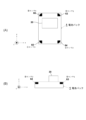
- FIG. 2 is a view of the battery pack 1 of FIG. 1, where (A) is a vertical cross-sectional view and (B) is a cross-sectional view taken along line AA.
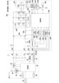
- 2 is a circuit diagram of a battery pack 1 and an electric device body 201 shown in FIG. 1.
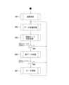
- FIG. FIG. 2 is a schematic diagram showing an example of installing sound sensors 63 to 66 in the battery pack of FIG. 1; 4 is a state transition diagram showing operation procedures of the battery pack 1 and the electric device main body 201 according to the embodiment.
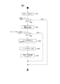
- FIG. FIG. 6 is a state transition diagram for explaining a detailed procedure in step 105 of FIG.
- FIG. 5; 5 is a flow chart showing a schematic control procedure in a sensor output mode of the controller 50 of the battery pack 1 according to the embodiment;
- FIG. 8 is a flowchart showing a detailed procedure of data reception processing 120 of FIG. 7;
- FIG. 8 is a flowchart showing a detailed procedure of sensor processing 140 of FIG. 7;
- FIG. FIG. 8 is a flowchart showing a detailed procedure of data transmission processing 150 of FIG. 7;
- FIG. FIG. 3 is a block diagram showing the overall configuration of an electrical equipment main body 301 according to a second embodiment of the present invention;
- FIG. 12 is a top view for explaining the operation of the electrical equipment main body 301 of FIG. 11;
- FIG. 11 is a block diagram showing the circuit configuration of an electrical equipment main body 301 according to a second embodiment; 10 is a flow chart showing a schematic control procedure in the control unit 350 of the electrical equipment main body 301 according to the second embodiment;
- FIG. 15 is a flowchart showing a detailed procedure of activation processing 501 in FIG. 14;
- FIG. 15 is a flow chart showing a detailed procedure of data reception processing 502 in FIG. 14;
- 15 is a flowchart showing a detailed procedure of control mode switching processing 503 of FIG. 14;
- FIG. 18 is a flowchart showing a detailed procedure of communication standby processing 546 of FIG. 17;
- FIG. FIG. 15 is a flow chart showing a detailed procedure of sound data processing 505 in FIG. 14;
- FIG. 15 is a flowchart showing a detailed procedure of motor control 507 in FIG. 14;
- FIG. FIG. 12 is a top view for explaining a change in irradiation angle of the electrical equipment main body 301 of FIG. 11;
- FIG. 10 is a diagram for explaining a method of controlling an electric device 401 according to the third embodiment using the battery pack 1 of the present invention (No. 1);
- FIG. 10 is a diagram for explaining a method of controlling an electric device 401 according to the third embodiment using the battery pack 1 of the present invention (No. 2);
- FIG. 11 is a diagram for explaining a method of controlling an electric device 401 according to a third embodiment using the battery pack 1 of the present invention (No. 3);
- FIG. 11 is a diagram for explaining a method of controlling an electric device 601 according to the fourth embodiment using the battery pack 1 of the present invention (No. 1);
- FIG. 12 is a diagram for explaining a method of controlling an electric device 601 according to the fourth embodiment using the battery pack 1 of the present invention (No. 2);
- FIG. 12 is a diagram for explaining a method of controlling an electric device 601 according to the fourth embodiment using the battery pack 1 of the present invention (No. 3);
- FIG. 12 is a flow chart showing the control procedure of the control unit 650 of the electrical equipment main body 601 according to the fourth embodiment;
- FIG. 10A is a perspective view showing the appearance of an electric device main body (radio) 801 according to a fifth embodiment of the present invention, where (A) is a perspective view seen from the front upper side, and (B) is a perspective view seen from the rear lower side. It is a diagram.
- FIG. 30 is a block diagram showing the circuit configuration of an electric device main body 801 and a battery pack 1 shown in FIG. 29;
- FIG. 30 is a flow chart showing the operation of a control unit 850 of the electrical equipment main body 801 shown in FIG. 29.
- FIG. FIG. 32 is a flow chart showing a detailed procedure of volume control in step 905 of FIG. 31;
- FIG. 1 is a perspective view of a battery pack 1 and a main body of an electrical device 201 (hereinafter sometimes referred to as an electrical device main body 201) according to an embodiment of the present invention.
- An example of an impact tool is shown as the electrical equipment main body 201 .
- the main body of the electric device 201 uses the detachable battery pack 1 as a power source, and performs the tightening work by driving the tip tool 209 using the rotational driving force of the motor.
- a main body of the electric device 201 has a housing 202 which is an outer frame forming an outer shape.
- the housing 202 includes a body portion 202a that accommodates a motor and a power transmission mechanism (not shown), a handle portion 202b that extends downward from the body portion 202a, and a battery pack mounting portion 202c that is formed below the handle portion 202b. .
- a trigger-like trigger switch 206 (see FIG. 3, which will be described later for reference numerals) is provided on a portion of the handle portion 202b, and a trigger lever 206a of the trigger switch 206 protrudes.
- a normal/reverse switching lever 207 is provided above the trigger switch 206 for switching the rotation direction of the motor.
- An anvil (not visible in the drawing) as an output shaft is provided on the front side of the housing 202, and a tip tool holding portion 208 for mounting a tip tool 209 is provided at the tip of the anvil.
- a plus driver bit is attached as the tip tool 209 .
- the battery pack mounting portion 202c has rail portions 211a and 211b including grooves and rails extending in parallel in the front-rear direction on both left and right inner wall portions, and a terminal portion (body-side terminal portion) 215 is provided between them.
- the terminal portion 215 is manufactured by integrally molding a non-conductive material such as synthetic resin, and has a plurality of metal terminals such as a positive input terminal 232, a first signal terminal 234, a second signal terminal 236, and a negative input terminal 237 attached thereto. , a third signal terminal 238 and a fourth signal terminal 235 .
- the terminal part 215 is manufactured by casting a plurality of metal terminals (232, 234 to 238) by molding synthetic resin, and has a vertical surface 215a that serves as an abutting surface in the mounting direction (front-rear direction) and a horizontal surface 215b. is formed as
- the terminal portion 215 is fixed so as to be sandwiched between the opening portions (not visible in the drawing) of the left and right split type battery pack mounting portion 202c.
- a horizontal surface 215b of the terminal portion 215 is a surface that is close to and faces the upper surface 13 on the battery pack 1 side when the battery pack 1 is attached.
- a curved portion 212 that abuts on the raised portion 15 of the battery pack 1 is formed on the front side of the horizontal surface 215 b , and a projecting portion 214 is formed near the left-right center of the curved portion 212 .
- the battery pack 1 is detachable from the main body of the corresponding electric device 201, and accommodates a plurality of battery cells in a case made of synthetic resin.
- rail grooves 18a and 18b (not visible in FIG. 1) for mounting on the main body of the electric device 201 and rail grooves 18a and 18b (not visible in FIG. 1) for realizing electrical connection with the main body of the electric device 201 are provided.
- a latch mechanism (latch portion) for maintaining or releasing the attached state between the slot portion 20, a group of connection terminals (described later in FIG. 3) arranged inside the slot portion 20, and the main body portion of the electric device 201. is provided.
- the latch mechanism includes latch buttons 16a and 16b and locking claws 17a and 17b (not visible in FIG. 1) that move in conjunction with the latch buttons 16a and 16b.
- Two rail grooves 18a and 18b are formed on the side surface of the upper case (first case) 10. As shown in FIG. The rail grooves 18a and 18b are formed so that their longitudinal direction is parallel to the mounting direction of the battery pack 1 .
- the battery pack 1 accommodates a plurality of battery cells therein and can output a DC rated voltage (for example, 18 V).
- the voltage of the battery pack 1 and the type of battery cells used are arbitrary. It should be noted that the output voltage of the battery pack 1 may be configured to switch between low and high voltages. After removing the battery pack 1 from the main body of the electrical device 201, it can be charged using an external charger (not shown).
- FIGS. 2A and 2B are diagrams showing a battery pack 1 according to an embodiment of the present invention, where (A) is a top view and (B) is a cross-sectional view taken along the line AA.
- the battery pack 1 has a synthetic resin housing composed of an upper case 10 and a lower case 2 .
- the upper case 10 and the lower case 2 are manufactured by integral molding of polycarbonate.
- a flat lower stage surface 11 is formed on the rear side of the upper case 10, and an upper stage surface 13 formed higher than the lower stage surface 11 is formed near the center.
- the lower step surface 11 and the upper step surface 13 are formed in a stepped shape, and the connecting portion between them is a stepped portion 12 which is a vertical surface.
- a slot portion arrangement area (slot portion) 20 is formed on the rear side portion of the upper step surface 13 from the stepped portion 12 .
- a plurality of (here, eight) notched slots 21 to 28 are formed on the upper surface parallel to the mounting direction (front-rear direction) and the vertical rear surface (stepped portion 12).
- the slots 21 to 28 are notched portions having a predetermined length in the battery pack mounting direction (front-rear direction) and a predetermined width in a direction crossing the battery pack mounting direction (horizontal direction).
- a positive electrode terminal (C+ terminal) used for charging the battery cell is provided in the inner space of the slot 21 , and a positive electrode terminal 32 for discharging (see FIG. 3 for the reference numeral) is accommodated in the slot 22 .
- the slots 23 are spare terminal insertion openings, and terminals are not provided in this embodiment.
- a first signal terminal 34 (T terminal) is accommodated in the slot 24 .
- the T terminal is used to output a signal that serves as identification information of the battery pack 1 to the electrical equipment main body 201 or an external charging device (not shown).
- the slot 25 is provided with a fourth signal terminal (V terminal) 35, which is used to input a control signal from an external charging device (not shown).
- the fourth signal terminal 35 does not have to be used when it is attached to a device other than the external charging device.
- a second signal terminal (LS terminal) 36 is accommodated in the slot 26, and temperature information of the battery is output by a temperature sensing element (not shown) provided in contact with the battery cells contained in the battery pack 1. Together, it communicates with the main body of the electrical device 201 .
- a negative terminal 37 is accommodated in the slot 27 .
- a third signal terminal (LD terminal) 38 is accommodated in the slot 28, and an over-discharge protection signal (abnormal stop signal) by a main body output control circuit 52 (described later in FIG. 3) for battery protection is transmitted to the connected equipment ( It is output to the electrical equipment main body 201 or an external charging device (not shown).
- a protruding portion 15 is formed on the front side of the upper stage surface 13 so as to protrude.
- the protruding portion 15 has an outer shape protruding upward from the upper stage surface 13, and a depression-like stopper portion 15a is formed in the vicinity of the center thereof.
- the stopper portion 15a serves as an abutting surface for the protrusion 214 (see FIG. 1) when the battery pack 1 is attached to the battery pack attachment portion 202c.
- a plurality of terminals (apparatus-side terminals) provided on the main body of the electrical device 201 and a plurality of connection terminals provided on the battery pack 1 (refer to FIG. 4 to be described later) are connected. ) come into contact with each other and become conductive.
- a plurality of slits 13a serving as cooling air outlets are provided inside the stopper portion 15a.
- Latch buttons 16a and 16b are provided on both left and right side surfaces of the front portions of the rail grooves 18a and 18b.
- the latch buttons 16a, 16 are biased by springs so as to be slidable in the lateral direction with respect to the upper case 10 (the springs are not visible in the figure).
- the latching claws 17a and 17b protrude in the left-right direction at the bottom (inside) of the rail grooves 18a and 18b (see FIG. 1) due to the action of the spring, and engage the rails of the main body of the electrical device 201 shown in FIG. Battery pack 1 is prevented from falling off by engaging recesses formed in portions 211a and 211b (see FIG. 1).
- the engaging claws 17a and 17b fixed in conjunction with the latch buttons 16a and 16b move inward. Then, the protruding state of the locking claws 17a and 17b from the rail grooves 18a and 18b is eliminated. After the protruding state is eliminated, the battery pack 1 can be removed from the main body of the electric device 201 by sliding the battery pack 1 in the extending direction of the rail grooves 18a and 18b.
- a display portion 80 is provided on the front slope of the raised portion 15 .
- the display unit 80 is provided with four display windows 81 to 84 , and a push button type switch button 85 is provided on the left side of the display window 81 .
- the switch button 85 is an operation unit operated by the user. LEDs (light-emitting diodes) are arranged inside the display windows 81 to 84 and light up appropriately.
- the switch button 85 is pushed by the user, the remaining battery level is displayed on the display windows 81 to 84 according to the remaining battery level of the battery pack 1 . Further, by pressing the switch button 85 for a long time, it functions as a button for instructing another operation to the control unit of the battery pack 1 .
- FIG. 2B is a cross-sectional view taken along line AA of FIG.
- the lower case (second case) 2 has a substantially rectangular parallelepiped shape with an open upper surface, and the internal space formed by the upper case 10 and the lower case 2 accommodates ten cylindrical battery cells 41 . be done.
- Ten battery cells 41 are fixed by separators 42 in a state in which five cells are stacked vertically in two stages.
- the type, size, and number of the battery cells 41 are arbitrary.
- lithium-ion battery cells called 18650 size which have a diameter of 18 mm and a length of 65 mm and can be charged and discharged multiple times, are used, and five cells are connected in series.
- the sets are connected in parallel to output a DC rated voltage of 18V.
- Vertically adjacent battery cells 41 are partitioned by flat upper and lower partition walls 44, and front and rear adjacent battery cells 41 are partitioned by flat front and rear partition walls 43 so that they are adjacent to each other. Battery cells 41 are not in contact.
- a circuit board 45 is fixed on the upper side of the separator 42 .
- a plurality of metal connection terminals (only the LD terminals 38 are visible here) are fixed (for example, soldered) to the circuit board 45 .
- a circuit pattern (not shown) is formed on the circuit board 45 to electrically connect the positive electrode side output and the negative electrode side output of the battery cell 41 to the connection terminal group.
- Various electronic elements such as a battery protection IC, a microcomputer, a storage memory, a PTC thermistor, a resistor, a capacitor, a fuse, and a light emitting diode are mounted on the circuit board 45 .
- four sound sensors 63 to 66 are mounted on the circuit board 45 in this embodiment.
- the sound sensors 63 to 66 are one of sensors (first sensors) for collecting sounds (sonic waves) arriving from the outside of the battery pack 1 .
- the sound sensors 63-66 correspond to the "sensor section" of the present invention.
- FIG. 3 is a circuit diagram of the battery pack 1 and the electrical equipment body 201.
- the battery pack 1 is provided with sensing sensors 61 to 69 such as acceleration sensors, and based on the signals from the sensors, the control unit 50 transmits the physical information input from the sensors 61 to 69 to the electric device main body side. is output as it is, or the physical information is processed and output so that it can be easily used on the electrical device 201 side.
- the battery pack 1 is electrically connected to the electrical equipment main body 201 via a plurality of connection terminals (32, 34, 36-38, etc.).
- the positive terminal 32 and the negative terminal 37 are power supply terminals connected to the positive and negative terminals of the battery cell 41 (battery cell set), and are connected to the positive input terminal 232 and the negative input terminal 237 of the electrical device main body 201 .
- a positive electrode side output of the battery cell 41 (battery cell set) is connected to the positive electrode terminal 32
- a negative electrode side output is connected to the negative electrode terminal 37 .
- the battery pack 1 is provided with a positive terminal for charging (so-called C+ terminal) as a terminal for electric power, but it is not illustrated here.
- the battery pack 1 is provided with at least one or more sensors 61 to 69 for sensing, either internally or externally.
- the conventional battery pack 1 is provided with a sensor for measuring voltage supplied from the battery cell 41, a sensor for measuring current, and a sensor for measuring temperature.
- the sensors 61 to 69 do not detect internal factors (battery cells 41) of the battery pack 1, but detect physical, optical, electrical, and magnetic factors caused by external factors of the battery pack 1. provided to detect any of the conditions. Examples of the sensors 61 to 69 include an acceleration sensor, a distance sensor (ranging sensor), an optical sensor, a human sensor, a position sensor, a sound sensor, an image sensor, and an illuminance sensor.
- any number of these sensors 61 to 69 may be provided in the battery pack 1, and one or a plurality of them may be provided. Further, like the second sensor 62, it may be attached to the outside of the battery pack 1 instead of being provided inside the case. In that case, it is preferable to provide a connector for connection at a position accessible from the outside of the battery pack 1 in order to perform electrical wiring between the sensor 62 and the control unit 50 .
- Each of the sensors 61 to 69 is intended to sense physical information, and is arranged at a position where the purpose can be achieved and which can be housed in the battery pack 1 or can be attached.
- the control unit 50 performs charge/discharge management of the battery cells, and also controls transmission of physical information acquired by the sensors 61 to 69 to the electrical equipment main body 201 side.
- the controller 50 corresponds to the "battery pack side controller" of the present invention.
- the control power supply circuit 51 converts the power of the battery cell 41 into a low voltage of 3.3 V or 5 V and outputs the low voltage to the control unit 50 .
- the control unit 50 is mounted on the circuit board 45 (see FIG. 2) and includes a microcomputer, a ROM for storing processing programs and control data, a RAM for temporarily storing data, a timer, and the like. be done.
- Outputs input from the sensors 61 to 69 are A/D converted by the microcomputer of the control unit 50, and sampling, noise removal processing, and other necessary processing are performed.
- a wireless communication circuit 55 is connected to the controller 50 .
- the wireless communication circuit 55 is a circuit for close proximity wireless communication such as Bluetooth (registered trademark).
- the radio communication circuit 55 is provided with an antenna 56 to enable communication within a distance of several tens of meters.
- the control unit 50 on the battery pack 1 side is configured to be able to communicate with the control unit 50 on the electrical device main body 201 side, and three signal terminals are used here.
- One is a second signal terminal (LS terminal) 36,236.
- the LS terminals 36 and 236 are communication terminals for transmitting the output of a thermistor (temperature sensing element) (not shown) provided for measuring the temperature of the battery cell 41. Also used as a communication terminal for receiving.
- the first signal terminals (T terminals) 34 and 234 transmit a signal that serves as identification information of the battery pack 1 to the electrical equipment main body 201 .
- the wired communication circuit 53 is a circuit for performing two-way wired communication with the battery communication circuit 260 of the electrical equipment main body 201 using signal terminals such as the LS terminals 36 and 236 and the T terminals 34 and 234 which are conventionally used.
- the third signal terminals (LD terminals) 38 and 238 are communication terminals for outputting an abnormal stop signal for protecting the battery cell 41 by the control unit 50 via the main body output control circuit 52. be.
- the electric device main body 201 is controlled by the control section 250 .
- the controller 250 corresponds to the "apparatus-side controller" of the present invention.
- a control power supply circuit 255 is provided to operate the control unit 250 .
- the control power supply circuit 255 is a power supply for generating a constant low voltage (for example, 3.3 V or 5 V) from direct current supplied to the positive input terminal 232 and the negative input terminal 237 . If the electrical equipment main body 201 is an impact tool as shown in FIG. 1, the battery pack 1 is attached to the main body of the electrical equipment 201, and when the trigger switch 206 is first pulled, the ON signal of the trigger switch 206 is controlled. Since it is input to the power supply circuit 255, the control unit 250 is activated.
- the self-holding circuit 259 continuously outputs a signal for keeping the control power supply circuit 255 in the ON state.
- the control signal input circuit 261 is a circuit that determines a signal transmitted from the battery pack 1 side via the third signal terminal (LD terminal) 238 and transmits the signal to the control section 250 .
- the battery communication circuit 260 is a circuit for performing two-way communication with the control section 50 of the battery pack 1 using the second signal terminal (LS terminal) 236 and the first signal terminal (T terminal) 234 .
- the control unit 250 includes a microcomputer for outputting drive signals based on processing programs and data, a ROM for storing processing programs and control data, a RAM for temporarily storing data, a timer, and the like.
- the motor 204 is a three-phase brushless DC motor driven by an inverter circuit 252 .
- the motor 204 is of a so-called inner rotor type, and includes a rotor 204a including a plurality of sets (two sets in this embodiment) of permanent magnets (magnets) including N and S poles, and a star. It has a stator 204b consisting of three-phase stator windings U, V, W that are connected.
- the control unit 250 receives the detection signals and controls the direction of current flow to the stator windings U, V, and W. and time are calculated, and the motor 204 is controlled to rotate at a predetermined number of revolutions.
- the inverter circuit 252 is composed of six switching elements (Q1 to Q6) such as FETs connected in a three-phase bridge configuration. Each gate of switching elements Q1-Q6 is connected to inverter control circuit 251, and each drain or source of switching elements Q1-Q6 is connected to star-connected stator windings U, V, W. FIG. As described above, the microcomputer included in the control unit 250 changes the DC power input to the inverter circuit 252 into three phases (U phase, V phase and W-phase) supplied to the stator 204b as voltages Vu, Vv, and Vw.
- the PWM signal is supplied to either one of the positive power supply side switching elements Q1 to Q3 or the negative power supply side switching elements Q4 to Q6 of the inverter circuit 252, and the switching elements Q1 to Q3 or the switching elements Q4 to Q6 are switched at high speed. Controls the power supplied to each stator winding U, V, W from DC by In this embodiment, since the PWM signal is supplied to the switching elements Q4 to Q6 on the negative power supply side, the power supplied to each stator winding U, V, W is adjusted by controlling the pulse width of the PWM signal. can be used to control the rotation speed of the motor 204 .
- a current value supplied to the motor 204 is measured by a current detection circuit 256 using a shunt resistor 253 and fed back to the control section 250 .
- the voltage value applied to the inverter circuit 252 is input to the control unit 50 by measuring the voltage across the capacitor 254 for smoothing by the voltage detection circuit 257 .
- the illumination LED 269 is a light-emitting device that illuminates the area where the tip tool is to be operated.
- the microcomputer of the control unit 250 detects that the operator has operated an illumination button (not shown) provided on the electrical equipment main body 201, and follows the instruction.
- the controller 250 turns on or off the illumination LED 269 .
- control unit 250 lights the mode display LED 268 or the illumination LED 269 in a predetermined lighting manner (blinking, display color change, etc.) according to a communication signal from the microcomputer (control unit 50) of the battery pack 1, thereby performing the work. It is possible to inform the person that the electrical equipment main body 201 is in a specific state.
- the operation mode switch 267 is a switch for setting the tightening strength of the impact tool or the like, the tightening mode, and the like. The operation mode set by the operation mode switch 267 is displayed by the corresponding mode display LED 268 which operation mode is selected.
- FIG. 4 is a schematic diagram showing an example of installing the sound sensors 63 to 66 in the battery pack 1.
- Sensors 63 to 66 for detecting sounds are for collecting sounds (sound waves) arriving from the outside of battery pack 1, and detect the magnitude of compressional waves propagating in air (medium).
- An electrodynamic, electrostatic, or piezoelectric microphone can be used as the sensors 63 to 66, and an electrostatic (capacitor) microphone is used here.
- the directions of the X-axis, Y-axis, and Z-axis are shown on the left side of the battery pack 1 .
- the X-axis, Y-axis, and Z-axis are positive in the direction indicated by the arrows.
- the four sensors 63-66 are used to detect the volume of sound detected by the four sensors 63-66.
- the reason why the four sensors 63 to 66 are provided in four directions is to detect from which direction the sound comes mainly in the horizontal plane (the plane passing through the X axis and the Y axis).
- Communication between the main body of the electrical device 201 and the battery pack 1 is performed by a wired communication circuit via signal connection terminals 34, 36, 38, etc., but any communication means may be used. and the battery pack 1 may be configured to communicate with each other.
- the control unit 250 can perform control according to the output signal of the sensor without adding a new sensor to the electrical equipment main body 201 side. rice field. Control of the electrical equipment main body 201 according to the output signals of the sensors 61 to 69 is performed by increasing/decreasing or stopping the output of the electrical equipment main body 201 by the control section 250 on the electrical equipment main body 201 side.
- the control configuration on the side of the electrical equipment main body 201 which is performed using various sensor signals of the battery pack 1, is as shown in (1) and (2) below.
- a sensor signal is received from the controller 50 of the battery pack 1 , and the body-side controller 250 controls the electrical device body 201 .
- (2) Sensor signal processing is performed by the control unit 50 of the battery pack 1, and the control unit 50 of the battery pack 1 controls the main body of the electric device 201 based on the result.
- control is performed on the electrical equipment main body 201 side by adopting the procedure (1).
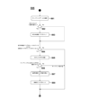
- FIG. 5 is a state transition diagram showing operation procedures of the battery pack 1 and the electrical equipment body 201 according to this embodiment.
- the transition diagram of FIG. 5 starts when the battery pack 1 is attached to the electrical equipment body 201 (step 101).
- the controller 50 of the battery pack 1 is activated (step 102).
- the control section 250 of the electrical equipment main body 201 is activated (step 282). Note that in a device (for example, an impact tool) that does not have a dedicated power switch in the electrical device main body 201, the control unit 250 is activated when the trigger switch 206 is first pulled.
- the controller 250 of the electrical equipment main body 201 transmits "equipment main body information" to the controller 50 of the battery pack 1 (step 283). That is, the battery pack 1 communicates with the main body of the electrical device 201 .
- the battery pack 1 communicates with the main body of the electrical device 201 .
- “sensor signal parameter output” is performed, and a “sensor output stop request” from the electrical device main body 201 or connection with the electrical device main body 201 is released ( By making a transition from a state in which communication is possible to a state in which communication is not possible, the "parameter output of the sensor signal” is stopped.
- the control unit 250 of the electrical equipment main body 201 transmits "equipment main body information" through the second signal terminal 36 and the second signal terminal 236 (step 283).
- the "equipment main body information” includes the model name of the electric equipment main body, information on the electric equipment main body necessary for utilizing sensor information, parameters necessary for controlling the electric equipment main body, and the like.
- the control section 50 of the battery pack 1 that has received the "equipment main body information” transmits the information of the mounted sensor among the sensors 61 to 69 to the control section 250 of the electric equipment main body 201 (step 104).
- the control unit 250 of the electric device main body 201 determines whether or not the attached battery pack 1 is compatible with the sensor control in the electric device main body 201 (step 284).
- step 285 the processing after step 285 is executed, and if the sensor control is not compatible, the subsequent steps are skipped, and the control unit 250 does not use the sensor information from the battery pack 1. Then, control of the electric equipment main body 201 is performed in the same manner as in the conventional art.
- the controller 250 of the electric device main body 201 determines that the operation mode currently set by the user 90 is a “sensor control mode” in which one or more of the sensors 61 to 69 mounted on the battery pack 1 are used. (step 285).
- the system stands by and does not execute the processing from step 286 onwards.
- the "sensor control mode” of step 285 is performed by the user 90 operating the "operation mode switch 267" provided on the electrical equipment body 201 (step 286).
- the operation mode switch may also be used as a switch (operation mode switch 267 in FIG. 3) for setting tightening strength, tightening mode, etc., or an operation panel on which various operation switches are arranged on the main body of the electric device 201.
- a new switch provided above may be used, and when the user 90 presses this change switch, the control unit 250 of the electrical equipment main body 201 transitions to the "sensor control mode" (step 288).
- the switch may be moved to the sensor control mode by performing a special operation such as pressing the switch for a long time.
- the control unit 250 of the electrical device body 201 that has shifted to the “sensor control mode” sends a sensor output request via the wired communication circuit 53, the second communication terminals 36 and 236, and the battery communication circuit 260. Then, an "information request signal (sensor output request signal)" is transmitted to the controller 50 of the battery pack 1 (step 290). Upon receiving the "information request signal (sensor output request signal)", the control unit 50 of the battery pack 1 switches to the "sensor output mode" (step 104). In the sensor output mode, the control unit 50 collects physical information using the mounted sensor among the sensors 61 to 69 and the target sensor whose output transmission is requested (step 106). .
- the battery pack 1 shown in FIG. 4 has sound sensors 63-66.
- control unit 50 of the battery pack 1 that has collected the physical information transmits the physical information together with the "battery pack information" to the control unit 250 of the electrical equipment body 201 (step 108).
- the physical information is transmitted to the control unit 250 via the wired communication circuit 53, the second communication terminals 36, 236, and the battery communication circuit 260.
- Acquisition timing and transmission timing of the physical information collected using the sensors 61-69 are then performed continuously or intermittently (for example, every clock time).
- the control unit 50 of the battery pack 1 continues to transmit the physical information collected using the sensors 61 to 69 to the electrical device main body 201 side, so the control unit 250 of the electrical device main body 201 Based on the transmitted physical information, control of the main body side of the electric device 201, in particular, rotation control of the motor 204, lighting, extinguishing, and illuminance control of the mode display LED 268 and the lighting LED 268 (see FIG. 3 for both). (step 293).
- Boxed steps 106 , 108 , and 293 of step 105 are executed when the battery pack 1 is removed from the main body of the electric device 201 or when the user 90 turns the operation mode switch 267 provided on the main body of the electric device 201 .
- the operation mode of the electrical equipment body 201 is continued until it is returned from the "sensor output mode” to the "normal mode".
- the control section 250 of the electrical equipment body 201 transmits an "information request stop signal (sensor output stop request signal)" to the control section 50 of the battery pack 1. (Step 295).
- An “information request stop signal (sensor output stop request signal)” is sent from the control unit 250 by wire through the battery communication circuit 260 , the second signal terminals 236 and 36 , and the wire communication circuit 53 .
- the control section 250 of the electrical equipment main body 201 returns to the "normal mode" in which the sensor output on the battery pack 1 side is not used.
- the control shown in FIG. 5 is terminated by turning off the power switch of the electrical device main body 201 or removing the battery pack 1 from the main body of the electrical device 201 (step 114).
- the controller 50 of the battery pack 1 collects physical information using information from the sensors 61-69.
- position information of the battery pack 1, inclination information of the battery pack 1, acceleration information of the battery pack 1, and the like can be considered.
- the control unit 50 stores the physical information, calculates the information of the battery pack 1 based on the physical information, and transmits the information to the control unit 250 of the electrical equipment body 201 (steps 107 to 109). .
- the control unit 250 of the electrical equipment body 201 controls the output of the load unit such as the motor 204 according to the received physical information and battery pack information (steps 291 and 292). This step 292 continues until the sensor output mode is canceled at step 294 in FIG.
- the control unit 250 of the electric device main body 201 terminates the sensor output mode (step 293), and transmits a control mode stop signal to the control unit 50 of the battery pack 1 (step 294).
- the control unit 50 of the battery pack 1 stops the control mode and shifts to the normal operation mode.
- FIG. 7 is a flow chart showing a schematic control procedure in the sensor output mode of the controller 50 of the battery pack 1 shown in FIG.
- the control unit 50 of the battery pack 1 mainly performs control in a loop of data reception processing 120 , sensor processing 140 and data transmission processing 150 .
- These loop controls are performed by pressing the operation mode switch 267 of the electrical equipment body 201 again and transmitting an "information request stop signal (sensor output stop request signal)" from the electrical equipment body 201 (step 295 in FIG. 5). can continue until
- FIG. 8 is a flow chart showing the detailed procedure of the data reception process 120 of FIG.
- the control unit 50 of the battery pack 1 determines whether or not communication data has been received from the outside (the control unit 250 of the electrical equipment body 201) (step 121). If there is reception, the control unit 50 performs reception processing of communication data (confirmation of command) (step 122).
- a command is prepared at the beginning of the communication data sent from the control unit 250 of the electrical equipment main body 201, and the control unit 50 of the battery pack 1 and the control unit 250 of the electrical equipment main body 201 communicate with this command type.
- Identify content For example, the data breakdown of communication data includes a command indicating a sensor output request at the beginning, followed by notification time (time interval for repeated transmission.
- sensor code output A designation code indicating any one of the sensors 61 to 69
- check data checksum
- the sensor code assigns binary bits in order to a plurality of sensors, assigns 1 to those that are used, and 0 to those that are not used. As an example, if the first and third sensors of the four sensors are used, the binary representation would be "0101".
- the control unit 50 determines whether or not the content of the command is "sensor output request" (step 123). If YES here, it is determined whether or not the checksum of the received data matches the checksum recreated by the control unit 50 (step 124).
- the code and notification time are extracted and updated and stored as sensor data in the control unit 50 of the battery pack 1 (step 125).
- the sensor code is used for power control of the sensor, and the notification time is used for transmitting the "parameter output of the sensor signal" in the "data transmission process” at regular intervals (step 126).
- the control unit 50 of the battery pack 1 transmits a response signal to the "sensor output request" signal to the electrical equipment body 201 (step 127).
- step 123 if the content of the command is "sensor output stop request processing” (step 128), the sensor code is cleared (step 129). As a result, the power supply for driving the sensors 61 to 69 of the battery pack 1 is turned off, and the transmission of the "parameter output of the sensor signal” is stopped. After that, the control unit 50 transmits a signal responding to the "sensor output stop request" to the electrical equipment body 201 (step 130). If No in step 128, other processing is performed and the process returns to step 121 (step 131). Note that other processing includes, for example, data processing of device main body information sent via communication, and information sent via communication (information to be received) includes the model name of the electrical device main body and sensor information. There are information on the main body of the electrical equipment necessary for utilization, parameters required for controlling the main body of the electrical equipment, and the like.
- step 141 the power state of each sensor 61 to 69 and the sensor code are collated.
- step 142 it is determined whether or not there is a change in the power state of the sensor (operational state due to power supply) (step 142).
- the power supply to each sensor 61 to 69 is controlled to be on or off according to the command sent from the electrical equipment main body 201 side (step 143). If it is determined in step 142 that there is no change in the power state of the sensor (operating state due to power supply), the process proceeds to step 144 .
- the controller 50 of the battery pack 1 determines whether or not there are any sensors 61 to 69 whose power is on (step 144). If there is a sensor 61 to 69 whose power is turned on, the detection data is obtained from the target sensor (any one of 61 to 69) (step 145). The acquired detection data is updated and held as data in the battery pack 1 (step 146). Next, when data acquisition from the necessary sensors 61 to 69 is completed, the control unit 50 sets the detection data acquisition completion flag of the sensor signal (step 147). This flag is used to count the time in the data transmission process and to enable or disable data transmission. If at step 144 there are no sensors 61-69 with power turned on, step 147 is followed.
- FIG. 10 is a flow chart showing the detailed procedure of the data transmission process 150 of FIG.
- data transmission is performed for each time period of the notification time set in the data reception process.
- the time count value is held as data in the battery pack, the time is counted, and the data is transmitted when the notification time has elapsed (the time count value is reset after transmission).
- the specific transmission conditions are (1) the parameters of the sensor signal are acquired. (The sensor signal detection data acquisition completion flag is set), (2) the device is connected (communication is possible), (3) the time count value matches the notification time (if not, the time count value is added).
- control unit 50 of the battery pack 1 determines whether or not the detection data acquisition completion flag of the sensor signal is set (step 151). If it is set here, the state of connection with the controller 250 of the electrical equipment body 201 is checked (step 152). If not, clear the time count value (step 163 ) and proceed to step 160 .
- the controller 50 of the battery pack 1 is electrically connected to the controller 250 of the electric device 201 and determines whether communication is possible (step 153). If it is determined in step 153 that the connection is not made, the sensor code is cleared (step 161), the time count value is cleared (step 163), and the process proceeds to step 160.
- step 153 it is determined whether or not the current time count value being counted matches the notification time (step 154).
- the control unit 50 sets the detected sensor data to the parameter of the sensor signal (step 155), and transmits it to the control unit 250 of the electrical equipment body 201 (step 155).
- This communication path goes through the wired communication circuit 53 , the second signal terminals 36 and 236 and the battery communication circuit 260 .
- the control unit 50 determines whether or not the notification time is 0 (step 157), clears the sensor code if it is 0 (step 158), and skips step 158 if it is not 0.
- control unit 50 clears the time count value (step 159) and clears the detection data acquisition completion flag of the sensor signal (step 160). If No at step 154 , that is, if the time count value does not match the notification time, the time count value is added by a predetermined unit (step 162 ), and the process proceeds to step 160 .
- the control unit 250 can perform various controls using additional sensor signals included in the battery pack 1 but not included in the electrical device main body 201 .
- the sensor signal output from the battery pack by the wired communication circuit of the battery pack (Fig. 1) is sent to the reception (input) via the wired communication circuit of the electrical device main body, and the electrical device main body transmits the sensor signal to the electrical device main body. Controls the output of the main unit.
- the control unit 50 of the battery pack 1 stops power supply to the sensors 61 to 69, and outputs sensor signals to the electric device main body side. Control not to send.
- the control unit 50 stops the power supply to the sensors 61 to 69 so as not to transmit sensor signals to the electrical equipment main body side.
- FIG. 11 is a block diagram showing the configuration of the electrical equipment body 301.
- the electric device main body 301 is a light having a mode (sound detection mode) in which a motor 304 controls an irradiation direction 314 of a light source 312 by an LED using the battery pack 1 as a power source so that it is directed in the direction of sound.
- An electric device main body (light device main body) 301 has a light section 303 that can rotate 360 degrees in the horizontal direction, and a light source 312 is provided in one direction of the light section 303 .
- the irradiation unit 310 has an LED (light emitting diode) as a light source 312 mounted on a substrate 311 and has a reflector 313 that guides the direction of light emission in one direction.
- the lighting device has the same structure as a known light device.
- the battery pack 1 is the same as the battery pack 1 shown in the first embodiment, has a connection terminal portion 30, and has a plurality (here, four) of sound sensors 63 to 66 (here, four) as sensors for collecting physical information. Reference numerals 65 and 66 refer to FIG. 12 described later).
- the electric device main body 301 has a mounting portion for mounting the battery pack 1, and the connecting terminal portion 320 is provided in the mounting portion.
- the electric power of the battery pack 1 is supplied to the control circuit board 345 of the electric device main body 301 by fitting the connection terminal portion 30 and the connection terminal portion 320 together.
- the main housing 302 of the electrical equipment main body 301 is provided with a power switch 330 for turning on the light source 312 and an operation mode switch 316 for setting whether or not to rotate the light unit 303 so as to follow the direction of sound. be done.
- Switching by the power switch 330 and the operation mode switch 316 is detected by a control circuit (especially a microcomputer not shown) mounted on the control circuit board 345, and the power supply to the light source 312 is turned on or off, or the power to the motor 304 is turned on or off. is supplied to rotate the light unit 303 .
- a control circuit especially a microcomputer not shown
- a motor 304 is a drive source for rotating a drive shaft 308 that supports the light unit 303, and is arranged so that the rotation shaft 305 is oriented vertically.
- the rotating shaft 305 is provided with a first gear 306 which is a spur gear.
- the lower end of the drive shaft 308 is rotatably supported by the main housing 302 and the other end is non-rotatably fixed to the light section 303 .
- a second gear 307 that is a large spur gear is fixed to the drive shaft 308 , and the rotational force of the motor 304 is transmitted to the drive shaft 308 in a reduced state by the meshing of the first gear 306 and the second gear 307 .
- a slip ring 309 is provided on the drive shaft 308 and below the second gear 307 to enable power supply from the control circuit board 345 to the light source 312 of the rotating light section 303 .
- the mounted motor 304 has a position detection means (not shown) capable of detecting its rotation angle, or the rotation position of the drive shaft 308 is discriminated by a microcomputer. It should be configured so that The mode can be switched by pressing the operation mode switch 316. There is a "normal mode” in which the light unit 303 is kept fixed without being rotated by the motor 304, and a mode in which the motor 304 is used to direct the sound in the direction from which the sound comes. It has a “sound detection mode” in which the light unit 303 is rotated by pressing. Note that this mode switching may be changed by transmitting a “control mode change request” from an external device such as a smartphone via the wireless communication circuit 55 of the battery pack 1 .
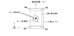
- FIG. 12 is a top view for explaining the operation of the light section 303 (see FIG. 11) of the electrical equipment main body 301.
- FIG. Four sound sensors 63 to 66 are provided at four corners near the upper surface of the battery pack 1 .
- the sensors 63-66 correspond to the "sensor section" of the present invention.
- the main housing 302 of the electrical equipment main body 301 does not rotate with respect to the battery pack 1 .
- a drive shaft 308 extends upward from the main housing 302 .
- the drive shaft 308 is rotatable by a motor 304 (see FIG. 11), and the light unit 303 (see FIG. 11) fixed to the top of the drive shaft 308 rotates.
- the control unit 350 (see FIG. 13 to be described later) of the electric device main body 301 performs data processing of sounds collected from the four sound sensors 63 to 66, and detects arrival of sound from a specific direction. Then, by driving the motor 304, the light irradiation direction 314 (see FIG. 11) can be controlled to be directed toward the estimated position 380 of the sound source. By controlling in this manner, it is possible to realize a light device that can emit light while following a work location when a worker performs work while moving at a work site or the like.
- FIG. 13 is a block diagram showing the circuit configuration of the electrical equipment body 301.
- the basic configuration is the same as the configuration shown in FIG.
- the electric device main body 301 is a light device
- the configuration of the light unit 303 is newly added.
- an LED control circuit 318 for lighting the LED 312 of the light unit 303 and a motor 304 for rotating the light unit 303 are added.
- the light unit 303 is provided with a light unit irradiation direction detection circuit 319 that detects the direction of the irradiation direction (how many degrees of rotation the angle is relative to the reference angle of 0 degrees in FIG. 12).
- the battery pack 1 that lights the LED 312 and supplies power to rotate the motor 304 has the same configuration as that of the first embodiment shown in FIG.
- the electric device main body 301 is provided with a first signal terminal 34 and a second signal terminal 36 as an input section, and is also provided with a positive terminal 32 and a negative terminal 37 . Illustrations of other configurations of the battery pack 1, other connection terminals (C+ terminal 31, third signal terminal 38), etc. are omitted.
- the electrical equipment main body 301 is entirely controlled by a control section 350 that operates with reference power supplied from a control power supply circuit 355 .
- the control unit 350 controls the rotation of the motor 304, receives outputs of various sensors (here, the sound sensors 63 to 66) from the control unit 50 side of the battery pack 1 via the wired communication circuit 360, and converts the received signals is processed, the rotation of the motor 304 is controlled according to the processing result, and the irradiation direction of the light unit 303 is controlled.
- the controller 350 corresponds to the "apparatus-side controller" of the present invention.
- the motor 304 is driven by a motor control circuit 351 under the control of the controller 350 .
- the motor 304 and the motor control circuit 351 used here are arbitrary, and can be controlled using, for example, a stepping motor.
- An LED control circuit 318 for lighting the light source 312 of the light unit 303 is controlled by the control unit 350 .
- the light section irradiation direction detection circuit 319 is configured using known position detection means, and outputs a signal indicating the rotation angle to the control section 350 .
- a microcomputer (not shown) of the control unit 350 controls the rotation of the motor 304 using the signal detected by the light unit irradiation direction detection circuit 319 and the physical information from the sensor received from the battery pack 1 .
- the switch operation detection circuit 317 detects ON/OFF of the operation mode switch 316 and outputs to the control unit 350 .
- a switch operation detection circuit 331 detects whether the power switch 330 is turned on or off, and outputs the result to the control unit 350 .
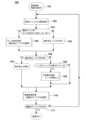
- FIG. 14 is a flow chart showing a schematic control procedure in the control section 350 of the electrical equipment main body 301 according to the second embodiment.
- the control related to the sensor output in the electrical equipment main body 301 is performed according to the procedure shown in FIG.
- the control unit 350 when the power switch 330 of the electrical equipment main body 301 is turned on, the control unit 350 is activated. At that time, the control unit 350 performs start-up processing (step 501).
- the control unit 350 performs reception processing for receiving physical information (here, “sound data”) acquired by the sensors 63 to 66 from the battery pack 1 (step 502).
- the current mode is the "sound detection mode”
- the process proceeds to step 505, and if the current mode is not the "sound detection mode”, the process returns to step 502 (step 504).
- the control section 350 processes the sensor information (here, sound data) transmitted from the battery pack 1 (step 505).
- the control unit 350 determines whether or not the "sound detection flag" has been set (step 506), and if it has been set, controls the motor (step 507), If not, the process returns from step 504 to step 502 .
- the control unit 350 of the electric device main body 301 performs data reception processing 502, sensor processing control mode switching processing 503, sound data processing 505 (if sound detection mode), motor control 507 (if sound is detected). 14 is repeated until the power switch 330 (see FIG. 11) is turned off.
- FIG. 15 is a flow chart showing the detailed procedure of the startup process 501 in FIG.
- the control unit 350 of the electrical equipment main body 301 reads the state flag of the control mode set from the built-in storage unit (not shown) at startup (step 511), and determines whether the state flag is the "sound detection mode”. It is determined whether or not (step 512). Here, in the case of the "sound detection mode", the "sensor output request processing" of steps 513 to 517 is performed. If the control mode is not the sound detection mode at step 511, the control section 350 controls the operation of the electrical equipment body 301 in the "normal mode".
- the connection state with the battery pack 1 is confirmed (step 513).
- the notification time and the sensor code are set in the "sensor output request” (step 515), and the "sensor output request ' is sent to the battery pack 1 (step 516), and the control mode change standby flag is set (step 517).
- the control mode change standby flag is a flag for checking whether a "sensor output request” or “sensor output stop request” has reached the battery pack 1, and is reset when a response arrives.
- step 514 if the battery pack 1 does not support the sound sensor, no request is made.
- FIG. 16 is a flow chart showing the detailed procedure of the data reception process 502 of FIG.
- the control unit 350 of the electrical device main body 301 determines whether or not data is received from the outside (battery pack 1) (step 521). If no data is received, skip the entire process of FIG. If data is received from the battery pack 1, the command sent is checked to identify the content of communication (step 522).
- the control unit 350 of the electrical equipment main body 301 determines whether the received command is a sensor signal parameter output (step 523). In the case of Yes at step 523, the control unit 350 of the electrical equipment body 301 performs "sampling data processing" (step 524).
- the control unit 350 of the electrical device main body 301 checks the received data, determines whether or not the checksums match, and updates the sampling data if the checksums match. As a result, the electric device body 301 holds the data obtained from the sound sensor as sampling data. Sampling data is retained for a certain period of time in the past.
- step 523 it is determined whether or not the received command is a response to the sensor output request (step 525).
- Yes "sound detection mode switching processing" is performed (step 526).
- the control unit 350 of the electric device main body 301 changes the control mode, clears the standby flag, clears the standby time count, clears the retransmission counter, and switches the control mode to the sound detection mode. Save the control mode and clear the sampling ring data.
- the standby time count is a value for counting a certain period of time when communication (transmission) is repeated when a desired response is not received within a certain period of time.
- step 525 it is determined whether or not the received command is a response to the sensor output stop request (step 527).
- Yes "normal mode switching processing” is performed (step 528).
- the control unit 350 of the electrical device main body 301 changes the control mode, clears the standby flag, clears the standby time count, clears the retransmission count, switches the control mode to the normal mode, to save.
- step 527 it is determined whether or not the received command is a control mode change request (step 529).
- other processing is performed.
- Other processing is, for example, data processing of information on the main body of electric equipment sent by communication. information on the main body of the electrical equipment, parameters necessary for controlling the main body of the electrical equipment, and the like.
- step 531 it is determined whether or not the specified mode is the normal mode (step 531).
- the normal mode "sensor output request processing” is performed (step 532).
- the control unit 350 of the electrical equipment main body 301 executes the same processes as steps 513 to 517 in FIG. If No in step 531, "sensor output stop request processing” is performed (step 533).
- the control unit 350 of the electrical device body 301 transmits a sensor output stop request and sets the control mode change standby flag.
- FIG. 17 is a flow chart showing the processing procedure when the operation mode switch 316 is pressed by the user.
- the control mode is changed when the operation mode switch 316 is pressed.
- the control unit 350 of the electrical equipment body 301 determines whether the operation mode switch 316 is pressed. (Step 541). If No in step 541 , the process proceeds to step 545 . If Yes at step 541, it is determined whether the current mode is normal mode or not (step 542).
- step 543 a sensor output request process is performed for the battery pack 1 (step 543).
- the control section 350 of the electrical equipment main body 301 executes the same processes as steps 513 to 517 in FIG. If No in step 542, that is, if the mode is not the normal mode, "sensor output stop request processing" is performed (step 544).
- the sensor output stop request process is the same as step 533 in FIG. 16, and the control unit 350 of the electrical equipment body 301 transmits the sensor output stop request and sets the control mode change standby flag.
- step 545 it is determined whether or not the control mode change standby flag is set (step 545). If Yes in step 545, that is, if the control mode change waiting flag is set, "communication waiting processing" is performed (step 546). If No in step 545, step 546 is skipped.
- FIG. 18 is a flow chart showing the detailed procedure of the communication standby process 546 of FIG.
- processing is performed until a response from the battery pack 1 reaches the control unit 350 of the electrical equipment main body 301 . If there is no response for a certain period of time, the sensor output request is resent to the battery pack 1, and if there is no response after resending the sensor output request a specified number of times, the transmission is stopped.
- the controller 350 of the electrical equipment main body 301 adds the standby time count (step 551).
- the control unit 350 determines whether or not the waiting time count has reached the retransmission waiting time (step 552). If the retransmission standby time has not been reached in step 552, the process of FIG.
- control unit 350 clears the waiting time count (step 554) and adds the number of retransmissions (step 555).
- the control unit 350 determines whether or not the number of retransmissions has reached a specified number of times. If not, the process of FIG. 18 is terminated. The number of times is cleared and the process of FIG. 18 is terminated (steps 557-559).
- FIG. 19 is a flow chart showing the detailed procedure of the sound data processing 505 in FIG.
- the controller 350 first confirms the sampling data received from the battery pack 1 (step 561), and stabilizes whether or not the sound volume exceeds a certain value (step 562). If the loudness of the sound exceeds the predetermined value, the control unit 350 sets a sound direction calculation flag (step 563), and skips to step 564 if it does not. Next, the control unit 350 determines whether the sound direction calculation flag is set or whether the sound detection flag remains set (step 564). If Yes in step 564, the control unit 350 uses the physical information from the four sound sensors 61 to 64 to calculate the direction of the sound from past sound data and subsequent sound data ( step 565).
- step 566 it is determined whether or not the direction of the sound can be estimated (step 566), and if it can be estimated, it is calculated as an angle A (see FIG. 21 described later) from the reference position (step 565).
- the control unit 350 sets the sound detection flag (step 568) and ends the processing of FIG. If the direction of the sound cannot be estimated in step 566, for example, if sampling of the sound data is insufficient, the process of FIG. 19 is terminated.
- FIG. 20 is a flow chart showing the detailed procedure of motor control 507 in FIG.
- the motor control 507 controls the light unit 303 to face the sound source by driving the motor 304 in the direction confirmed by the sound data processing 505 .
- the control section 350 of the electrical equipment main body 301 confirms the current direction in which the light section 303 is facing (step 571).
- control unit 350 determines whether motor 304 is in operation (step 572).
- step 572 determines whether the irradiation direction of the light unit 303 is directed toward the sound source direction, that is, whether the light arrival direction reaches the target direction (sound source direction) It is determined whether or not (step 573).
- step 573 If it is in the direction of the sound source in step 573, rotation of the motor 304 is stopped (step 574), the sound direction calculation flag and sound detection flag are cleared, and the processing of FIG. 20 is terminated (step 575). Also, in step 573, if the irradiation direction of the light unit 303 has not reached the target direction, the process of FIG. 20 is terminated and the process returns to step 506 of FIG.
- the sound direction calculation flag is a flag that is set when a threshold (loudness) for determining that a sound has been heard is exceeded, and is used to enter the flow for calculating the direction of sound.
- the sound detection flag is a flag that is set when the estimation of the sound direction is completed, and is used to enter the motor operation flow.
- step 572 If the motor is not operating in step 572 (if the motor 304 is not operating), the control section 350 calculates the rotation angle B° of the light section 303 from the reference position (step 576). Next, the control unit 350 determines whether the angle A (°) of the estimated position of the sound source is equal to the rotation angle B (°) (step 577). is cleared, and the process of FIG. 20 ends (step 578). In step 577, if A ⁇ B, the control unit 350 calculates the motor rotation speed and the direction of the sound source (step 579), sets the calculated direction as the target direction (step 580), and starts the motor 304. (step 581) and returns to step 506 in FIG.
- FIG. 21 is a top view for explaining the change of the irradiation angle of the electrical equipment main body 301 of FIG. 11.
- FIG. 14 to 20 using the outputs of the four sound sensors 63 to 66 mounted on the battery pack 1, the control unit 350 sets the rotation angle of the light unit 303 to the reference position (0 degree). , the light is directed in a direction rotated clockwise by B°.
- a "sensor output request (information request signal, sensor output request signal)" is sent to the battery pack 1, and the "sensor signal parameter output (physical information/battery
- the controller 350 controls the rotation of the motor 304 in accordance with the pack information or operating conditions.
- the irradiation direction is fixed at the time of switching or returns to the initial position.
- FIG. FIG. 22(A) is a left side view of the electric device main body 401
- (B) is the attitude of the battery pack 1 in the state of (A).
- the directions of the Y-axis and Z-axis shown in (B) are the directions with the battery pack 1 as a reference.
- the battery pack 1 can be attached to the battery pack attachment portion 402c by moving it relative to the electric device body 401 from the rear to the front in the direction indicated by the arrow. In other words, in FIGS.
- the mounting direction of the battery pack 1 with respect to the electrical equipment main body 401 is the front direction (the direction of the ⁇ Y axis).
- the information on the electrical equipment main body 401 includes the mounting direction of the battery pack 1 .
- One acceleration sensor may be provided in the battery pack 1, and in this embodiment, it is provided at the position of the sensor 64 in FIG.
- the electrical equipment main body 401 includes a base 410 that is placed on and slides on the object to be cut, a saw blade 405 that protrudes from an opening provided in the base 410 to the bottom surface of the base, a motor 404 that rotates the saw blade, and a motor 404 that rotates the saw blade. It has a handle portion 403 provided on the top of the housing that accommodates the .
- the handle portion 403 is provided with a trigger lever 406 for turning on the rotation of the motor 404 . Since the configuration of the electrical equipment main body 401 is well known, detailed description thereof will be omitted.
- the battery pack 1 Since the battery pack 1 is mounted in the electrical equipment main body in a horizontal state, when the electrical equipment main body 401 is in a horizontal state as shown in (A), the battery pack 1 is also in a horizontal state.
- the electrical equipment main body (circular saw) 401 is configured such that the amount of projection of the saw blade from below the base 410 (so-called depth of cut) can be changed. That is, it is configured such that the angle of the electrical device main body with respect to the base 410 can be changed.
- FIG. 22A shows a state in which the saw blade protrudes from the base 410 at its maximum.
- the electric device main body is in a state within the permitted operation range 480 (example of identification information) in FIG. 22(C). Therefore, within the range where the cutting depth can be adjusted, the electric device main body 401 is in a state within the operation permission range 480, and the cutting work can be performed.
- whether or not it is “within the operation allowable range 480” can be determined by the magnitude of the Y component and Z component in the output of the acceleration sensor 64, and ⁇ 0.87g ⁇ Y ⁇ 0.5g and Z >0 is determined to be within the operation allowable range.
- the dotted line on the horizontal axis is the absolute Y-axis direction (one direction passing through the horizontal plane)
- the dotted line on the vertical axis is the absolute Z-axis direction (one direction passing through the extension plane).
- the control unit 50 of the battery pack 1 receives information input from the acceleration sensor 64 (physical information including the attitude and orientation of the electrical device main body), or the battery pack that allows the electrical device main body 401 to operate based on the information.
- Information (battery pack information related to physical information) is output to the control unit 450 (corresponding to the control unit 250 in FIG. 3 and the control unit 350 in FIG. 13) of the electrical device main body 401 . The worker can continue working on the electrical device main body 401 thereafter.
- FIG. 23 shows a state in which the front side of the electric equipment main body 401 is turned upward by about 45 degrees from the state of FIG. 22(A).
- FIG. 4 is a plan view, and (B) shows the attitude of the battery pack 1 when the electric device main body 401 is in the state of (A). 22, the battery pack 1 in this posture assumes the same posture as shown in (B) together with the electric device main body 401. Therefore, the acceleration sensor 64 is affected by the gravitational acceleration. is 0.64 g in the Z-axis direction and 0.64 g in the Y-axis direction as shown in (C). This is outside the permitted operation range 480 described above.
- the control unit 50 of the battery pack 1 controls this posture information (physical information including the posture and orientation of the electrical device body), or battery pack information (physical information) prohibiting the operation of the electrical device body 401 based on the posture information.
- Battery pack information related to the information such as a stop signal, is output to the control unit 450 (not shown) of the electrical device main body 401 . As a result, work on the electrical device body 401 is prohibited (stopped).
- FIG. 24 shows a state in which the posture of the electrical equipment main body 401 is reversed and rotated about 150 degrees from the state shown in FIG. 22(A). This state corresponds to a working state in which an operator uses a circular saw to cut tree branches or cut a ceiling tree from below.
- FIG. 24(A) is a left side view of the electric device main body 401
- (B) is the attitude of the battery pack 1 in the state of (A).
- the battery pack 1 with the electrical equipment main body 401 in the posture of FIG. 24A is affected by the gravitational acceleration, and the detection value of the acceleration sensor 64 in the Z-axis direction is -0.87 g and in the Y-axis direction is 0.87 g. 5 g.
- the detected value in the Z-axis direction is a negative value because the acceleration sensor 64 is upside down. This is outside the permitted operation range 480 described above.
- the control unit 50 of the battery pack 1 controls this posture information (physical information including the posture and orientation of the electrical device body), or battery pack information (physical information) prohibiting the operation of the electrical device body 401 based on the posture information.
- Battery pack information related to the information such as a stop signal, is output to the control unit 250 of the electrical equipment main body 401 . As a result, work on the electrical device body 401 is prohibited (stopped).
- the control unit 50 of the battery pack 1 outputs posture information (physical information) input from the acceleration sensor 64 to the control unit 450 of the electric device body 401, or outputs the posture information Control for outputting the battery pack information (operation permission signal and operation prohibition signal of the electrical device main body 401) to the control unit 450 of the electrical device main body 401 has been described. With this control, it is possible to effectively prohibit the work of operating the circular saw in an inappropriate posture using the battery pack 1 with the sensor. 22 to 24, the detection results in the X-axis direction are not referred to for the sake of simplification of the explanation, but the detection results of all the three axes of the acceleration sensor 64, ie, the X-axis, the Y-axis, and the Z-axis.
- Further advanced control may be performed by referring to the posture determination. Further, the operation of the electric device main body 401 may be controlled using not only the acceleration sensor 64 but also the output of any one of the other sensors 63 , 65 and 66 .
- the operation of the electric device main body 401 may be controlled using not only the acceleration sensor 64 but also the output of any one of the other sensors 63 , 65 and 66 .
- the control unit of the battery pack 1 outputs the physical information input from the acceleration sensor 64 to the electrical device main body 401. Also good.
- the control section 450 of the electrical device main body 401 may control the operation based on the information obtained from this physical information and the mounting direction information of its own battery pack.
- the configuration in which the battery pack 1 slides in the horizontal direction (front-rear direction) with respect to the electric device main body 401 is described.
- a configuration in which the mounting direction of the battery pack 1 with respect to the electric device main body 601 (circular saw main body) is different will be described.
- the battery pack 1 is slid vertically (from top to bottom) and attached to the main body.
- FIG. 25 shows a case where the electrical device main body 601 is in a horizontal state
- (A) is a left side view of the electrical device 601
- (B) is the battery pack 1 in the state of (A).
- the battery pack 1 is, for example, vertically attached to the battery pack attachment portion 602c of the electrical equipment main body 601, and when the electrical equipment main body 601 is in the horizontal state as shown in (A), the battery pack 1 is in the vertical state.
- Information (physical information) is output to the control unit 650 of the electrical device main body 601, or battery pack information (for example, an operation permission signal of the electrical device main body 601) regarding the attitude information is sent to the control unit 650 of the electrical device main body 601.
- Output In FIG. 25C, the dotted line on the horizontal axis is the absolute Z-axis direction (one direction passing through the horizontal plane), and the dotted line on the vertical axis is the absolute Y-axis direction (one direction passing through the extension plane). .
- FIG. 26 shows a state in which the posture of the front side of the electric device main body 601 is turned upward by about 45 degrees from the state shown in FIG. 25(A).
- FIG. 26(A) is a left side view of the electric device main body 601
- (B) is the posture of the battery pack 1 in the state of (A).
- the battery pack 1 in this case has the detection values of the acceleration sensor 64 in the Y-axis direction and the Z-axis direction of -0 in the Y-axis direction as shown in (C). .64g, and 0.64g in the Z-axis direction. Since this falls outside the above-described permitted operation range 680, the control unit 50 of the battery pack 1 uses the attitude information (physical information) input from the acceleration sensor 64 as the electric device. It outputs to the control unit 250 of the main body 601 , or outputs battery pack information (for example, an operation prohibition signal for the electric device main body 601 ) related to the posture information to the control unit 650 of the electric device main body 601
- FIG. 27 shows a state in which the posture of the electrical equipment main body is reversed and rotated by about 150 degrees from the state shown in FIG. 25(A). This state corresponds to a working state in which an operator uses a circular saw to cut a tree branch from below or a ceiling tree from below.
- FIG. 27(A) is a left side view of the electric device main body 601
- (B) is the attitude of the battery pack 1 in the state of (A).
- the battery pack 1 in the posture shown in FIG. 27A is affected by gravitational acceleration, and the detection value of the acceleration sensor 64 in the Y-axis direction is 0.87 g, and the detection value in the Z-axis direction is 0.5 g. .
- the detected value in the Y-axis direction is a positive value because the acceleration sensor 64 is upside down. This is outside the allowable operation range 680 described above.
- Posture information (physical information) input from the acceleration sensor 64 is output to the control unit 250 of the electrical device main body 601, or battery pack information related to the posture information (for example, an operation prohibition signal of the electrical device main body 601) is electrically transmitted. It outputs to the control unit 250 of the device body 601 .
- the control of the control section 650 (corresponding to 250 in FIG. 3) of the electrical equipment main body 601 will be described using a flowchart 700 in FIG.
- the control unit is activated to turn on the electrical equipment (step 701).
- the controller 650 communicates with the battery pack 1 via a battery communication circuit (corresponding to 260 in FIG. 3) and a wired communication circuit (corresponding to 261 in FIG. 3) (not shown) (step 702).
- the control unit of the electrical device main body 601 receives battery pack information including information on whether the battery pack 1 is a sensor-compatible model and information detected by the acceleration sensor 64 of the battery pack 1 from the battery pack 1. (corresponding to step 104 in FIG. 5), the information of the electric equipment main body 601, for example, the model name and control parameter information of itself is transmitted to the battery pack 1 (corresponding to step 283 in FIG. 5).
- the control unit 650 executes sensor signal processing based on physical information (orientation information) obtained from the acceleration sensor 64 of the battery pack 1. (step 704).
- This sensor signal processing as described with reference to FIGS. sets (turns on) an operation prohibition flag (step 704).
- Control unit 650 sets operation permission range 680 based on the mounting direction of battery pack 1 with respect to electric device main body 601 of itself. If it is within the operation permission range 680, the operation permission flag may be set.
- the operation prohibition flag is reset (turned off) (step 705).
- step 706 when the operation prohibition flag is set (Yes in step 706), the control unit 650 prohibits the driving of the electric device main body and notifies the operator of the prohibition of operation by, for example, an LED (step 707). End (step 710).
- the operation prohibition flag is not set (No in step 706), it is determined whether the trigger switch is operated to execute normal operation (step 708). If so (Yes in step 708), a process for operating the electrical equipment main body (motor) is executed (step 709). If the trigger switch has not been operated (No in step 708), the control ends (step 710). Finally, the control unit 650 determines whether or not the power OFF flag is turned on (step 711). Turn off. If the power OFF flag is not turned off at step 711 (No at step 711 ), the process returns to step 702 .
- the control procedure has been described with the configuration in which the battery pack 1 is vertically mounted on the electrical equipment main body 601 .
- the mounting direction of the battery pack 1 with respect to the electric equipment main body is not limited to this, and the electric equipment main body 401 configured to be mounted in the front-rear direction like the third embodiment shown in FIGS. can be applied in the same manner, and can also be applied in the same manner to an electrical equipment main body in which the battery pack 1 is installed in the left-right direction or in the oblique direction.
- the number of battery packs 1 that can be attached to the electrical device main bodies 401 and 601 at the same time is not limited to one, and may be plural.
- the physical information of the acceleration sensor in each battery pack or the battery pack information related to the physical information is transmitted to the electric device main bodies 401 and 601. If configured to transmit, the control unit of the electric device main body 401 or 601 can control its own operation based on the sensor information and information that can be detected by itself (for example, mounting direction information of the battery pack 1).
- FIG. 29 is an external view of a specific device as the electrical device main body 801, showing an example of a radio here.
- FIG. 29(A) is a perspective view of the electric device main body 801 as seen from the front upper side.
- the electrical device main body 801 uses the battery pack 1 as a power source and automatically adjusts the volume (output value) output from the speaker 806 in accordance with the volume of the surrounding sound (automatic volume adjustment mode).
- the fifth embodiment is not limited to radios, and can be widely applied to televisions whose volume can be adjusted, and other audio equipment.
- a radio main body 801 as an electric device main body includes a handle 803 held by a user, an operation panel 805 operated by the user and having a power button, a volume adjustment button, a mode switching button, and a channel switching button, and a volume display and a channel display. and a speaker 806 provided on the front surface of the main body.
- FIG. 29B is a perspective view of the electric device main body 801 viewed from the rear and lower side, and a battery pack mounting portion 810 for mounting the battery pack 1 is provided on the back side of the housing 802 of the radio main body 801 .
- the shape of the battery pack mounting portion 810 is the same as (compatible with) the battery pack mounting portion 202c shown in FIG.
- a terminal portion (body-side terminal portion) is provided between them.
- An AC adapter connection portion 811 for connecting a connector of an AC adapter (not shown) is provided near the battery pack mounting portion 810 .
- FIG. 30 is a block diagram showing the configuration of the electrical equipment main body 801. As shown in FIG. Since the configuration of the battery pack 1 shown on the left side is the same as the configuration shown in FIG. 3, the same reference numerals are used to omit repeated description.
- the electric device main body 801 is a radio, and the radio waves received by the AM antenna 821 and the FM antenna 822 are detected by the DSP radio IC 820 , amplified by the amplifier circuit 823 , and output by the speaker 806 as sound.
- the electric device main body 801 includes a control section 850 that communicates with the control section 50 included in the battery pack 1 .
- the electrical equipment body 801 is provided with a positive input terminal 832 and a negative input terminal 837, which are connected to the positive terminal 32 and the negative terminal 37 of the battery pack 1, respectively.
- the battery pack 1 is provided with a positive electrode terminal for charging (so-called C+ terminal) as a terminal for electric power, but the illustration is omitted here.
- the electric device main body 801 has a first signal terminal (T terminal) 834, a second signal terminal (LS terminal) 836, a third A signal terminal (LD terminal) 838 is provided.
- a control signal input circuit 861 is connected to the third signal terminal (LD terminal) 838 .
- the control signal input circuit 861 determines the signal transmitted from the battery pack 1 side and outputs it to the control section 850 .
- the battery communication circuit 860 is connected to a first signal terminal (T terminal) 834 and a second signal terminal (LS terminal) 836, and uses the signal terminals of the LS terminals 36, 836 and the T terminals 34, 834 to communicate with the battery pack 1. Two-way wired communication with the wired communication circuit 53 is performed.
- DSP radio IC 820 incorporates all necessary functions for receiving AM and FM radio in one IC by digitally calculating analog signals input from AM antenna 821 and FM antenna 822 using a processor. A commercially available product can be used. DSP radio IC 820 outputs an audio signal to amplifier circuit 823 .
- the power button 856 is operated by the user, drive power is supplied from the control power supply circuit 855 to the control unit 850, the DSP radio IC 820, the amplifier circuit 823, etc., and the electrical equipment main body 801 is activated.
- the self-holding circuit 859 continuously outputs a signal for keeping the control power supply circuit 855 on, and power supply from the control power supply circuit 855 to the control unit 850 is maintained.
- the volume adjustment button 831 is an operation button for adjusting the volume of the sound output from the speaker 806, and has two buttons, for example, a + button (increase volume) and a - button (decrease volume). Configured.
- the mode switching button 832 is operated when switching between the automatic volume adjustment mode (first mode) and the normal mode (second mode) according to this embodiment.
- the control unit 850 adjusts the volume according to the user's operation of the volume adjustment button (adjustment unit) 831 in the "normal mode", and obtains the volume from a sensor such as a microphone provided in the battery pack 1 in the "automatic volume adjustment mode".
- a channel switching button 833 is a switching button for switching the broadcast channel set in the storage device of the control unit 850 .
- a display unit 804 is a known dot matrix display means such as a liquid crystal display device, and visibly displays various information such as channel display, volume display, and mode display of "normal mode” or "volume automatic adjustment mode". do.
- FIG. 31 is a flowchart (900) showing the operation of the control unit 850.
- the controller 850 executes start-up processing (step 901).
- the control unit 850 executes processing of data and operations received via the battery communication circuit 860, the control signal input circuit 861, and the buttons of the operation panel 805 (see FIG. 30) (step 902), and performs control mode switching processing. (step 903).
- step 904 volume control is performed to automatically adjust the volume according to the ambient sound (step 905), and return to step 902;
- the control unit 850 adjusts the volume set according to the operation of the volume adjustment button 831, and step 902 back to
- the control unit 850 When the “volume automatic adjustment mode” is set, the control unit 850 outputs the output volume from the speaker 806 according to the ambient sound (external volume) received by the sound sensors 63 to 66 (the amplification factor of the amplifier circuit 823). automatically adjust.
- the external sound pressure level obtained from the sound sensors 63 to 66 of the battery pack 1 is calculated. In this case, it is preferable to perform auditory correction, adjust the magnitude for each frequency, and add them up for calculation. If the calculated sound pressure level of the external volume is less than the threshold A, the control unit 850 sets the output volume to W (step 952). is set to X (step 953).
- the sound pressure level to be compared with the threshold value A can be determined by a method of comparing the peak value of the sound pressure, a method of comparing the average value, a method of comparing the sound pressure value weighted by a specific frequency, time, etc., as appropriate. should be set. Furthermore, if the external volume is greater than or equal to the threshold B and less than the threshold C, the controller 850 sets the output volume to Y (step 954), and if the external volume is greater than or equal to the threshold C, sets the output volume to Z. (step 955).
- the output volume has a relationship of W ⁇ X ⁇ Y ⁇ Z.
- the radio 801 shown in FIG. 29 also has a variable mechanism that automatically rotates the speaker 806 so that it faces the direction in which the external sound is generated or the direction in which the sound is loud. You can add it.
- the variable parts and variable settings of the electrical equipment main body side shown in the fifth embodiment may be adjusted.
- the illuminance of the light 301 may be automatically adjusted in accordance with not only the irradiation direction but also the ambient brightness.
- a fan driven by the battery pack 1 can also be used as the main body of the electrical equipment. The adjustment may be performed automatically, or the air volume of the fan may be automatically adjusted according to the ambient temperature measured by the temperature sensor provided in the battery pack 1 .
- the setting of the sound detection mode in FIG. 21 may be configured to be changed by a "control mode change request" from an external device (for example, a smart phone) via wireless communication of the battery pack.
- an external device for example, a smart phone
- Wired communication circuit 55... Wireless communication Circuit 56 Antenna 61 to 69 Sensor 80 Display 81 Display window 85 Switch button 90 User 120 Data reception process 140 Sensor process 150 Data transmission process 201 Electrical equipment (body) 202 Housing 202a Body 202b Handle 202c Battery pack mounting part 204 Motor 204a Rotor 204b Stator 206 Trigger switch 206a Trigger lever , 207 forward/reverse switching lever 208 tip tool holding portion 209 tip tool 211a, 211b rail portion 212 curved portion 214 protrusion 215 terminal portion 215a vertical surface 215b horizontal surface , 232...positive input terminal, 234...first signal terminal (T terminal), 235...fourth signal terminal (V terminal), 236...second signal terminal (LS terminal), 237...negative input terminal, 238...third SIGNAL TERMINAL (LD TERMINAL) 250 (main body side) control unit 251 inverter control circuit 252 inverter circuit 253 shunt resistor 254 capacitor 255 control power supply circuit 256 current detection circuit 257
- Electric apparatus main body 302... Main housing, 303... Light part, 304... Motor, 305... Rotary shaft, 306... First gear, 307... Second gear, 308... Drive shaft..., 309... Slip ring, 310... Irradiation unit 311... Substrate 312... Light source (LED) 313... Reflector 314... (Light) irradiation direction 316... Operation mode switch 317... Switch operation detection circuit 318... LED control circuit 319...
Landscapes
- Chemical & Material Sciences (AREA)
- Chemical Kinetics & Catalysis (AREA)
- Electrochemistry (AREA)
- General Chemical & Material Sciences (AREA)
- Engineering & Computer Science (AREA)
- Manufacturing & Machinery (AREA)
- Mechanical Engineering (AREA)
- Life Sciences & Earth Sciences (AREA)
- Biophysics (AREA)
- Computer Hardware Design (AREA)
- Microelectronics & Electronic Packaging (AREA)
- Battery Mounting, Suspending (AREA)
Priority Applications (4)
| Application Number | Priority Date | Filing Date | Title |
|---|---|---|---|
| US18/574,732 US20240387888A1 (en) | 2021-09-29 | 2022-09-28 | Battery pack and electrical device |
| DE112022004665.1T DE112022004665T5 (de) | 2021-09-29 | 2022-09-28 | Batterie-paket und elektrisches gerät |
| CN202280047514.5A CN117597820A (zh) | 2021-09-29 | 2022-09-28 | 电池组及电气设备 |
| JP2023551583A JPWO2023054445A1 (https=) | 2021-09-29 | 2022-09-28 |
Applications Claiming Priority (2)
| Application Number | Priority Date | Filing Date | Title |
|---|---|---|---|
| JP2021-158765 | 2021-09-29 | ||
| JP2021158765 | 2021-09-29 |
Publications (1)
| Publication Number | Publication Date |
|---|---|
| WO2023054445A1 true WO2023054445A1 (ja) | 2023-04-06 |
Family
ID=85782796
Family Applications (1)
| Application Number | Title | Priority Date | Filing Date |
|---|---|---|---|
| PCT/JP2022/036104 Ceased WO2023054445A1 (ja) | 2021-09-29 | 2022-09-28 | 電池パック及び電気機器 |
Country Status (5)
| Country | Link |
|---|---|
| US (1) | US20240387888A1 (https=) |
| JP (1) | JPWO2023054445A1 (https=) |
| CN (1) | CN117597820A (https=) |
| DE (1) | DE112022004665T5 (https=) |
| WO (1) | WO2023054445A1 (https=) |
Cited By (1)
| Publication number | Priority date | Publication date | Assignee | Title |
|---|---|---|---|---|
| US20250205840A1 (en) * | 2023-12-20 | 2025-06-26 | National Kaohsiung University Of Science And Technology | Self-powered sensing tool holder |
Citations (3)
| Publication number | Priority date | Publication date | Assignee | Title |
|---|---|---|---|---|
| JP2003018753A (ja) * | 2001-07-02 | 2003-01-17 | Sony Corp | 充電装置及び二次電池 |
| JP2020500399A (ja) * | 2017-11-10 | 2020-01-09 | フォリクル, エルエルシーFollicle, LLC | 電池式ヘアドライヤー |
| WO2020213450A1 (ja) * | 2019-04-19 | 2020-10-22 | 株式会社村田製作所 | 電池パック、非燃焼式吸引器、電子機器、電動工具及び無人飛行体 |
Family Cites Families (8)
| Publication number | Priority date | Publication date | Assignee | Title |
|---|---|---|---|---|
| JP3076489B2 (ja) * | 1993-12-15 | 2000-08-14 | 株式会社東芝 | 電気自動車 |
| JP4342161B2 (ja) * | 2002-09-18 | 2009-10-14 | ヤマハ発動機株式会社 | 燃料電池システム |
| JP4759921B2 (ja) | 2004-02-13 | 2011-08-31 | 日立工機株式会社 | 電池パック及び電動工具 |
| JP5065958B2 (ja) * | 2008-03-26 | 2012-11-07 | パナソニック株式会社 | 電池パック |
| KR101097248B1 (ko) * | 2009-10-26 | 2011-12-21 | 삼성에스디아이 주식회사 | 배터리 팩 보호회로, 배터리 팩 보호방법, 및 전기 자전거 |
| TW201349627A (zh) * | 2012-05-31 | 2013-12-01 | Emerald Battery Technologies Co Ltd | 電池監控及保護裝置及其系統與方法 |
| KR20160144786A (ko) * | 2015-06-09 | 2016-12-19 | 주식회사 엘지화학 | 배터리 팩 보호 시스템 및 방법 |
| JP2019042850A (ja) | 2017-08-31 | 2019-03-22 | 工機ホールディングス株式会社 | アダプタ |
-
2022
- 2022-09-28 DE DE112022004665.1T patent/DE112022004665T5/de active Pending
- 2022-09-28 US US18/574,732 patent/US20240387888A1/en active Pending
- 2022-09-28 WO PCT/JP2022/036104 patent/WO2023054445A1/ja not_active Ceased
- 2022-09-28 JP JP2023551583A patent/JPWO2023054445A1/ja active Pending
- 2022-09-28 CN CN202280047514.5A patent/CN117597820A/zh not_active Withdrawn
Patent Citations (3)
| Publication number | Priority date | Publication date | Assignee | Title |
|---|---|---|---|---|
| JP2003018753A (ja) * | 2001-07-02 | 2003-01-17 | Sony Corp | 充電装置及び二次電池 |
| JP2020500399A (ja) * | 2017-11-10 | 2020-01-09 | フォリクル, エルエルシーFollicle, LLC | 電池式ヘアドライヤー |
| WO2020213450A1 (ja) * | 2019-04-19 | 2020-10-22 | 株式会社村田製作所 | 電池パック、非燃焼式吸引器、電子機器、電動工具及び無人飛行体 |
Cited By (1)
| Publication number | Priority date | Publication date | Assignee | Title |
|---|---|---|---|---|
| US20250205840A1 (en) * | 2023-12-20 | 2025-06-26 | National Kaohsiung University Of Science And Technology | Self-powered sensing tool holder |
Also Published As
| Publication number | Publication date |
|---|---|
| DE112022004665T5 (de) | 2024-09-12 |
| JPWO2023054445A1 (https=) | 2023-04-06 |
| US20240387888A1 (en) | 2024-11-21 |
| CN117597820A (zh) | 2024-02-23 |
Similar Documents
| Publication | Publication Date | Title |
|---|---|---|
| CN101064439B (zh) | 充电装置 | |
| CN201298578Y (zh) | 电池充电器和电动工具系统 | |
| US20160329729A1 (en) | Adapter for cordless power tools | |
| WO2019022072A1 (ja) | 電池パック及び電池パックを用いた電気機器 | |
| CN103796802B (zh) | 用于对由电池驱动的手持工具设备进行电流监控的方法和装置 | |
| CN103975499A (zh) | 电池控制系统 | |
| TW201221318A (en) | Power tool and battery pack for use in the power tool | |
| JP7355134B2 (ja) | バッテリパック及びシステム | |
| CN103522262B (zh) | 用电池运行的手持式设备的控制 | |
| TW201728040A (zh) | 具備無線通訊功能之電池式電源裝置 | |
| WO2023054445A1 (ja) | 電池パック及び電気機器 | |
| CN114556985B (zh) | 电池组及电气设备系统 | |
| JP2004135496A (ja) | バッテリ駆動型の手持式電動工具 | |
| JP6793335B2 (ja) | 充電アダプタ | |
| JP2014091176A (ja) | 電動工具 | |
| EP2415658B1 (en) | Multifunction power supplying device for a bicycle | |
| JP2015118062A (ja) | 電池種類判別装置およびこれを備えた電池駆動型の電子機器 | |
| CN114829073A (zh) | 用于与以蓄电池运行的加工设备的至少一个操作者交互的方法以及用于执行该方法的系统 | |
| JPWO2023054445A5 (https=) | ||
| JP2010170779A (ja) | 電池パック及び工具システム | |
| US20150002074A1 (en) | Electronic speed controller with automatic detection for type of battery | |
| JP2020194639A (ja) | 電池パック及び電気機器 | |
| JP2014204449A (ja) | 電池パック及び充電器 | |
| JP2006116641A (ja) | 電動駆動体 | |
| JP7758966B2 (ja) | 電池パック及び電動工具 |
Legal Events
| Date | Code | Title | Description |
|---|---|---|---|
| 121 | Ep: the epo has been informed by wipo that ep was designated in this application |
Ref document number: 22876311 Country of ref document: EP Kind code of ref document: A1 |
|
| WWE | Wipo information: entry into national phase |
Ref document number: 18574732 Country of ref document: US |
|
| WWE | Wipo information: entry into national phase |
Ref document number: 202280047514.5 Country of ref document: CN |
|
| WWE | Wipo information: entry into national phase |
Ref document number: 2023551583 Country of ref document: JP |
|
| 122 | Ep: pct application non-entry in european phase |
Ref document number: 22876311 Country of ref document: EP Kind code of ref document: A1 |