WO2023054445A1 - 電池パック及び電気機器 - Google Patents
電池パック及び電気機器 Download PDFInfo
- Publication number
- WO2023054445A1 WO2023054445A1 PCT/JP2022/036104 JP2022036104W WO2023054445A1 WO 2023054445 A1 WO2023054445 A1 WO 2023054445A1 JP 2022036104 W JP2022036104 W JP 2022036104W WO 2023054445 A1 WO2023054445 A1 WO 2023054445A1
- Authority
- WO
- WIPO (PCT)
- Prior art keywords
- battery pack
- main body
- control unit
- information
- output
- Prior art date
Links
- 230000001133 acceleration Effects 0.000 claims description 39
- 230000008859 change Effects 0.000 claims description 19
- 239000002184 metal Substances 0.000 claims description 5
- 229910052751 metal Inorganic materials 0.000 claims description 5
- 238000000034 method Methods 0.000 description 83
- 230000006854 communication Effects 0.000 description 66
- 238000004891 communication Methods 0.000 description 65
- 238000012545 processing Methods 0.000 description 63
- 238000001514 detection method Methods 0.000 description 51
- 230000008569 process Effects 0.000 description 41
- 238000010586 diagram Methods 0.000 description 22
- 230000005540 biological transmission Effects 0.000 description 20
- 230000004044 response Effects 0.000 description 9
- 238000005070 sampling Methods 0.000 description 9
- 230000007704 transition Effects 0.000 description 6
- 238000004364 calculation method Methods 0.000 description 5
- 210000000078 claw Anatomy 0.000 description 5
- 238000005520 cutting process Methods 0.000 description 5
- 238000005286 illumination Methods 0.000 description 5
- 238000003825 pressing Methods 0.000 description 5
- 238000004804 winding Methods 0.000 description 5
- 239000003990 capacitor Substances 0.000 description 4
- 230000007246 mechanism Effects 0.000 description 4
- 238000005192 partition Methods 0.000 description 4
- 229920003002 synthetic resin Polymers 0.000 description 4
- 239000000057 synthetic resin Substances 0.000 description 4
- 238000012508 change request Methods 0.000 description 3
- 230000005484 gravity Effects 0.000 description 3
- 238000000465 moulding Methods 0.000 description 3
- 238000003860 storage Methods 0.000 description 3
- 241000209094 Oryza Species 0.000 description 2
- 235000007164 Oryza sativa Nutrition 0.000 description 2
- 230000002159 abnormal effect Effects 0.000 description 2
- 230000003247 decreasing effect Effects 0.000 description 2
- 230000006870 function Effects 0.000 description 2
- 230000003287 optical effect Effects 0.000 description 2
- 235000009566 rice Nutrition 0.000 description 2
- 239000000758 substrate Substances 0.000 description 2
- HBBGRARXTFLTSG-UHFFFAOYSA-N Lithium ion Chemical compound [Li+] HBBGRARXTFLTSG-UHFFFAOYSA-N 0.000 description 1
- 230000009471 action Effects 0.000 description 1
- 230000004913 activation Effects 0.000 description 1
- 230000003321 amplification Effects 0.000 description 1
- 230000008901 benefit Effects 0.000 description 1
- 230000004397 blinking Effects 0.000 description 1
- 238000005266 casting Methods 0.000 description 1
- 230000015556 catabolic process Effects 0.000 description 1
- 238000004590 computer program Methods 0.000 description 1
- 238000012790 confirmation Methods 0.000 description 1
- 238000001816 cooling Methods 0.000 description 1
- 238000012937 correction Methods 0.000 description 1
- 238000007599 discharging Methods 0.000 description 1
- 238000009429 electrical wiring Methods 0.000 description 1
- 230000005520 electrodynamics Effects 0.000 description 1
- 238000005516 engineering process Methods 0.000 description 1
- 238000009499 grossing Methods 0.000 description 1
- 238000003780 insertion Methods 0.000 description 1
- 230000037431 insertion Effects 0.000 description 1
- 239000004973 liquid crystal related substance Substances 0.000 description 1
- 229910001416 lithium ion Inorganic materials 0.000 description 1
- 239000011159 matrix material Substances 0.000 description 1
- 238000012986 modification Methods 0.000 description 1
- 230000004048 modification Effects 0.000 description 1
- 239000012811 non-conductive material Substances 0.000 description 1
- 238000003199 nucleic acid amplification method Methods 0.000 description 1
- 239000004417 polycarbonate Substances 0.000 description 1
- 229920000515 polycarbonate Polymers 0.000 description 1
- 230000001902 propagating effect Effects 0.000 description 1
- 230000000717 retained effect Effects 0.000 description 1
- 230000005236 sound signal Effects 0.000 description 1
Images


Classifications
-
- B—PERFORMING OPERATIONS; TRANSPORTING
- B25—HAND TOOLS; PORTABLE POWER-DRIVEN TOOLS; MANIPULATORS
- B25F—COMBINATION OR MULTI-PURPOSE TOOLS NOT OTHERWISE PROVIDED FOR; DETAILS OR COMPONENTS OF PORTABLE POWER-DRIVEN TOOLS NOT PARTICULARLY RELATED TO THE OPERATIONS PERFORMED AND NOT OTHERWISE PROVIDED FOR
- B25F5/00—Details or components of portable power-driven tools not particularly related to the operations performed and not otherwise provided for
-
- H—ELECTRICITY
- H01—ELECTRIC ELEMENTS
- H01M—PROCESSES OR MEANS, e.g. BATTERIES, FOR THE DIRECT CONVERSION OF CHEMICAL ENERGY INTO ELECTRICAL ENERGY
- H01M10/00—Secondary cells; Manufacture thereof
- H01M10/42—Methods or arrangements for servicing or maintenance of secondary cells or secondary half-cells
- H01M10/48—Accumulators combined with arrangements for measuring, testing or indicating the condition of cells, e.g. the level or density of the electrolyte
-
- H—ELECTRICITY
- H01—ELECTRIC ELEMENTS
- H01M—PROCESSES OR MEANS, e.g. BATTERIES, FOR THE DIRECT CONVERSION OF CHEMICAL ENERGY INTO ELECTRICAL ENERGY
- H01M50/00—Constructional details or processes of manufacture of the non-active parts of electrochemical cells other than fuel cells, e.g. hybrid cells
- H01M50/20—Mountings; Secondary casings or frames; Racks, modules or packs; Suspension devices; Shock absorbers; Transport or carrying devices; Holders
- H01M50/204—Racks, modules or packs for multiple batteries or multiple cells
- H01M50/207—Racks, modules or packs for multiple batteries or multiple cells characterised by their shape
- H01M50/213—Racks, modules or packs for multiple batteries or multiple cells characterised by their shape adapted for cells having curved cross-section, e.g. round or elliptic
-
- H—ELECTRICITY
- H01—ELECTRIC ELEMENTS
- H01M—PROCESSES OR MEANS, e.g. BATTERIES, FOR THE DIRECT CONVERSION OF CHEMICAL ENERGY INTO ELECTRICAL ENERGY
- H01M50/00—Constructional details or processes of manufacture of the non-active parts of electrochemical cells other than fuel cells, e.g. hybrid cells
- H01M50/20—Mountings; Secondary casings or frames; Racks, modules or packs; Suspension devices; Shock absorbers; Transport or carrying devices; Holders
- H01M50/247—Mountings; Secondary casings or frames; Racks, modules or packs; Suspension devices; Shock absorbers; Transport or carrying devices; Holders specially adapted for portable devices, e.g. mobile phones, computers, hand tools or pacemakers
-
- H—ELECTRICITY
- H01—ELECTRIC ELEMENTS
- H01M—PROCESSES OR MEANS, e.g. BATTERIES, FOR THE DIRECT CONVERSION OF CHEMICAL ENERGY INTO ELECTRICAL ENERGY
- H01M50/00—Constructional details or processes of manufacture of the non-active parts of electrochemical cells other than fuel cells, e.g. hybrid cells
- H01M50/20—Mountings; Secondary casings or frames; Racks, modules or packs; Suspension devices; Shock absorbers; Transport or carrying devices; Holders
- H01M50/284—Mountings; Secondary casings or frames; Racks, modules or packs; Suspension devices; Shock absorbers; Transport or carrying devices; Holders with incorporated circuit boards, e.g. printed circuit boards [PCB]
-
- H—ELECTRICITY
- H01—ELECTRIC ELEMENTS
- H01M—PROCESSES OR MEANS, e.g. BATTERIES, FOR THE DIRECT CONVERSION OF CHEMICAL ENERGY INTO ELECTRICAL ENERGY
- H01M50/00—Constructional details or processes of manufacture of the non-active parts of electrochemical cells other than fuel cells, e.g. hybrid cells
- H01M50/20—Mountings; Secondary casings or frames; Racks, modules or packs; Suspension devices; Shock absorbers; Transport or carrying devices; Holders
- H01M50/296—Mountings; Secondary casings or frames; Racks, modules or packs; Suspension devices; Shock absorbers; Transport or carrying devices; Holders characterised by terminals of battery packs
-
- Y—GENERAL TAGGING OF NEW TECHNOLOGICAL DEVELOPMENTS; GENERAL TAGGING OF CROSS-SECTIONAL TECHNOLOGIES SPANNING OVER SEVERAL SECTIONS OF THE IPC; TECHNICAL SUBJECTS COVERED BY FORMER USPC CROSS-REFERENCE ART COLLECTIONS [XRACs] AND DIGESTS
- Y02—TECHNOLOGIES OR APPLICATIONS FOR MITIGATION OR ADAPTATION AGAINST CLIMATE CHANGE
- Y02E—REDUCTION OF GREENHOUSE GAS [GHG] EMISSIONS, RELATED TO ENERGY GENERATION, TRANSMISSION OR DISTRIBUTION
- Y02E60/00—Enabling technologies; Technologies with a potential or indirect contribution to GHG emissions mitigation
- Y02E60/10—Energy storage using batteries
Definitions
- the present invention relates to battery packs and electrical equipment.
- Patent Literature 1 discloses an adapter that is mounted between a battery pack and an electric device main body and that includes an inclination sensor, a control section, and a signal output terminal.
- the controller of the adapter when the tilt sensor detects that the tilt detected by the tilt sensor is greater than a predetermined value, the controller of the adapter outputs a stop signal from the signal output terminal to the electric device main body, and the battery pack is stopped. is configured to cut off the power supply from the main body of the electrical equipment.
- Patent Document 2 describes a configuration in which a sensor is provided in a battery pack to suppress an increase in the size of an electrical device.
- a battery pack is provided with an acceleration sensor and a control section, the control section on the battery pack side detects the impact by the impact tool main body, and the control section turns off a switching element provided on the battery pack side.
- an impact tool configured to cut off power supply from a battery pack to an impact tool body.
- the impact tool of Patent Document 2 cuts off the power supply inside the battery pack based on the decision of the battery pack. Therefore, when connected to an impact tool that generates a large impact force, the impact can be detected, but if it is connected to an impact tool that generates a small impact force, the impact cannot be detected. Conceivable. In order to increase versatility, it is considered useful to perform control according to device information output from an electrical device main body such as an impact tool to be connected. In addition, since the battery pack is used by being connected to various electrical equipment main bodies, convenience can be improved by providing a sensor capable of detecting information other than impact detection.
- the present invention has been made in view of the above background. It is to provide an electric device using it. Another object of the present invention is to provide a battery pack with improved convenience and an electric device using the same. Another object of the present invention is to provide a battery pack with various sensors and send sensor information from the battery pack to the electrical equipment main body so that the control unit of the electrical equipment main body can perform control using the sensor information. The purpose of the present invention is to provide a battery pack and an electric device using the battery pack.
- the battery pack has a sensor section configured to collect and output physical information caused by external factors of the battery pack, and a battery pack control section connected to the sensor section.
- the battery pack control unit is configured to output the physical information input from the sensor unit to the electrical equipment main body, or generate battery pack information related to the physical information and output it to the electrical equipment main body. bottom. Also, it is configured to execute control according to physical information input from the sensor unit.
- the physical information caused by external factors includes information on the position, orientation, or acceleration of the battery pack.
- the battery pack control section is configured to be able to communicate with the device side control section of the electrical device main body.
- the battery pack has a plurality of metal connection terminals that enable electrical connection with the electrical equipment main body, and some of the connection terminals are used for wired connection with the electrical equipment main body.
- communication by The battery pack control section is configured to be able to change operating conditions of the electrical device main body according to physical information detected by the sensor section.
- the battery pack control unit is configured to be able to change the operating conditions of the electric device main body according to the connected electric device main body.
- An electrical device has been realized that includes an electrical device main body having such a battery pack, a battery pack mounting section to which the battery pack can be mounted, and a load section driven by the battery pack.
- a battery pack attachable to an electrical device main body having a device-side control unit is configured to collect and output physical information caused by external factors of the battery pack.
- the device includes a sensor section and a battery pack side control section connected to the sensor section and receiving device information output from the device side control section.
- the battery pack-side control unit transmits a signal for controlling the electrical device main unit to the electrical device main unit, and the device-side control unit outputs the sensor unit output signal.
- the output signal of the sensor unit is configured to be transmitted to the electrical equipment main body.
- the electrical device main body has a device-side control section, and the device-side control section stores information regarding the mounting direction of the battery pack with respect to the battery pack mounting section, and physical information output from the battery pack. information or battery pack information to control the load unit.
- the device-side control section prohibits driving the load section when the physical information or the battery pack information does not match the mounting direction information.
- the information on the mounting direction of the battery pack with respect to the electrical equipment includes the permitted operation range based on the mounting direction of the battery pack when the main body of the electrical equipment is placed normally. If the pack information is out of the allowable range of operation, the drive of the load section is prohibited.
- the electrical equipment main body includes an output unit capable of outputting light or sound and capable of rotating, and an equipment-side control unit that controls rotation of the output unit.
- the information or battery pack information includes information about sounds generated around the electric device main body, and the device side control unit is configured to change the output direction or output value of the light or sound of the output unit based on the information about the sounds. be done.
- the electric device is operated by a user and includes an adjustment unit that adjusts the output of the output unit, and the device-side control unit controls the output unit in a first mode based on information about sound, and the operation of the adjustment unit. and a second mode of controlling the output based on the second mode.
- the battery pack and electric equipment which enable control according to the equipment information output from the connected electric equipment main body can be provided, suppressing the enlargement of an electric equipment. Also, it is possible to provide a battery pack with improved convenience and an electric device using the same. Further, according to the present invention, the battery pack is provided with various sensors, and sensor information is sent from the battery pack to the electrical equipment main body so that the control section of the electrical equipment main body can perform control using the sensor information. It is possible to provide a battery pack and an electric device using the same.
- FIG. 2 is a perspective view of a main body portion of an electric device main body 201 and a battery pack 1 according to an embodiment of the present invention
- FIG. 2 is a view of the battery pack 1 of FIG. 1, where (A) is a vertical cross-sectional view and (B) is a cross-sectional view taken along line AA.
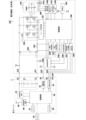
- 2 is a circuit diagram of a battery pack 1 and an electric device body 201 shown in FIG. 1.
- FIG. FIG. 2 is a schematic diagram showing an example of installing sound sensors 63 to 66 in the battery pack of FIG. 1; 4 is a state transition diagram showing operation procedures of the battery pack 1 and the electric device main body 201 according to the embodiment.
- FIG. FIG. 6 is a state transition diagram for explaining a detailed procedure in step 105 of FIG.
- FIG. 5; 5 is a flow chart showing a schematic control procedure in a sensor output mode of the controller 50 of the battery pack 1 according to the embodiment;
- FIG. 8 is a flowchart showing a detailed procedure of data reception processing 120 of FIG. 7;
- FIG. 8 is a flowchart showing a detailed procedure of sensor processing 140 of FIG. 7;
- FIG. FIG. 8 is a flowchart showing a detailed procedure of data transmission processing 150 of FIG. 7;
- FIG. FIG. 3 is a block diagram showing the overall configuration of an electrical equipment main body 301 according to a second embodiment of the present invention;
- FIG. 12 is a top view for explaining the operation of the electrical equipment main body 301 of FIG. 11;
- FIG. 11 is a block diagram showing the circuit configuration of an electrical equipment main body 301 according to a second embodiment; 10 is a flow chart showing a schematic control procedure in the control unit 350 of the electrical equipment main body 301 according to the second embodiment;
- FIG. 15 is a flowchart showing a detailed procedure of activation processing 501 in FIG. 14;
- FIG. 15 is a flow chart showing a detailed procedure of data reception processing 502 in FIG. 14;
- 15 is a flowchart showing a detailed procedure of control mode switching processing 503 of FIG. 14;
- FIG. 18 is a flowchart showing a detailed procedure of communication standby processing 546 of FIG. 17;
- FIG. FIG. 15 is a flow chart showing a detailed procedure of sound data processing 505 in FIG. 14;
- FIG. 15 is a flowchart showing a detailed procedure of motor control 507 in FIG. 14;
- FIG. FIG. 12 is a top view for explaining a change in irradiation angle of the electrical equipment main body 301 of FIG. 11;
- FIG. 10 is a diagram for explaining a method of controlling an electric device 401 according to the third embodiment using the battery pack 1 of the present invention (No. 1);
- FIG. 10 is a diagram for explaining a method of controlling an electric device 401 according to the third embodiment using the battery pack 1 of the present invention (No. 2);
- FIG. 11 is a diagram for explaining a method of controlling an electric device 401 according to a third embodiment using the battery pack 1 of the present invention (No. 3);
- FIG. 11 is a diagram for explaining a method of controlling an electric device 601 according to the fourth embodiment using the battery pack 1 of the present invention (No. 1);
- FIG. 12 is a diagram for explaining a method of controlling an electric device 601 according to the fourth embodiment using the battery pack 1 of the present invention (No. 2);
- FIG. 12 is a diagram for explaining a method of controlling an electric device 601 according to the fourth embodiment using the battery pack 1 of the present invention (No. 3);
- FIG. 12 is a flow chart showing the control procedure of the control unit 650 of the electrical equipment main body 601 according to the fourth embodiment;
- FIG. 10A is a perspective view showing the appearance of an electric device main body (radio) 801 according to a fifth embodiment of the present invention, where (A) is a perspective view seen from the front upper side, and (B) is a perspective view seen from the rear lower side. It is a diagram.
- FIG. 30 is a block diagram showing the circuit configuration of an electric device main body 801 and a battery pack 1 shown in FIG. 29;
- FIG. 30 is a flow chart showing the operation of a control unit 850 of the electrical equipment main body 801 shown in FIG. 29.
- FIG. FIG. 32 is a flow chart showing a detailed procedure of volume control in step 905 of FIG. 31;
- FIG. 1 is a perspective view of a battery pack 1 and a main body of an electrical device 201 (hereinafter sometimes referred to as an electrical device main body 201) according to an embodiment of the present invention.
- An example of an impact tool is shown as the electrical equipment main body 201 .
- the main body of the electric device 201 uses the detachable battery pack 1 as a power source, and performs the tightening work by driving the tip tool 209 using the rotational driving force of the motor.
- a main body of the electric device 201 has a housing 202 which is an outer frame forming an outer shape.
- the housing 202 includes a body portion 202a that accommodates a motor and a power transmission mechanism (not shown), a handle portion 202b that extends downward from the body portion 202a, and a battery pack mounting portion 202c that is formed below the handle portion 202b. .
- a trigger-like trigger switch 206 (see FIG. 3, which will be described later for reference numerals) is provided on a portion of the handle portion 202b, and a trigger lever 206a of the trigger switch 206 protrudes.
- a normal/reverse switching lever 207 is provided above the trigger switch 206 for switching the rotation direction of the motor.
- An anvil (not visible in the drawing) as an output shaft is provided on the front side of the housing 202, and a tip tool holding portion 208 for mounting a tip tool 209 is provided at the tip of the anvil.
- a plus driver bit is attached as the tip tool 209 .
- the battery pack mounting portion 202c has rail portions 211a and 211b including grooves and rails extending in parallel in the front-rear direction on both left and right inner wall portions, and a terminal portion (body-side terminal portion) 215 is provided between them.
- the terminal portion 215 is manufactured by integrally molding a non-conductive material such as synthetic resin, and has a plurality of metal terminals such as a positive input terminal 232, a first signal terminal 234, a second signal terminal 236, and a negative input terminal 237 attached thereto. , a third signal terminal 238 and a fourth signal terminal 235 .
- the terminal part 215 is manufactured by casting a plurality of metal terminals (232, 234 to 238) by molding synthetic resin, and has a vertical surface 215a that serves as an abutting surface in the mounting direction (front-rear direction) and a horizontal surface 215b. is formed as
- the terminal portion 215 is fixed so as to be sandwiched between the opening portions (not visible in the drawing) of the left and right split type battery pack mounting portion 202c.
- a horizontal surface 215b of the terminal portion 215 is a surface that is close to and faces the upper surface 13 on the battery pack 1 side when the battery pack 1 is attached.
- a curved portion 212 that abuts on the raised portion 15 of the battery pack 1 is formed on the front side of the horizontal surface 215 b , and a projecting portion 214 is formed near the left-right center of the curved portion 212 .
- the battery pack 1 is detachable from the main body of the corresponding electric device 201, and accommodates a plurality of battery cells in a case made of synthetic resin.
- rail grooves 18a and 18b (not visible in FIG. 1) for mounting on the main body of the electric device 201 and rail grooves 18a and 18b (not visible in FIG. 1) for realizing electrical connection with the main body of the electric device 201 are provided.
- a latch mechanism (latch portion) for maintaining or releasing the attached state between the slot portion 20, a group of connection terminals (described later in FIG. 3) arranged inside the slot portion 20, and the main body portion of the electric device 201. is provided.
- the latch mechanism includes latch buttons 16a and 16b and locking claws 17a and 17b (not visible in FIG. 1) that move in conjunction with the latch buttons 16a and 16b.
- Two rail grooves 18a and 18b are formed on the side surface of the upper case (first case) 10. As shown in FIG. The rail grooves 18a and 18b are formed so that their longitudinal direction is parallel to the mounting direction of the battery pack 1 .
- the battery pack 1 accommodates a plurality of battery cells therein and can output a DC rated voltage (for example, 18 V).
- the voltage of the battery pack 1 and the type of battery cells used are arbitrary. It should be noted that the output voltage of the battery pack 1 may be configured to switch between low and high voltages. After removing the battery pack 1 from the main body of the electrical device 201, it can be charged using an external charger (not shown).
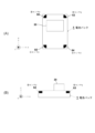
- FIGS. 2A and 2B are diagrams showing a battery pack 1 according to an embodiment of the present invention, where (A) is a top view and (B) is a cross-sectional view taken along the line AA.
- the battery pack 1 has a synthetic resin housing composed of an upper case 10 and a lower case 2 .
- the upper case 10 and the lower case 2 are manufactured by integral molding of polycarbonate.
- a flat lower stage surface 11 is formed on the rear side of the upper case 10, and an upper stage surface 13 formed higher than the lower stage surface 11 is formed near the center.
- the lower step surface 11 and the upper step surface 13 are formed in a stepped shape, and the connecting portion between them is a stepped portion 12 which is a vertical surface.
- a slot portion arrangement area (slot portion) 20 is formed on the rear side portion of the upper step surface 13 from the stepped portion 12 .
- a plurality of (here, eight) notched slots 21 to 28 are formed on the upper surface parallel to the mounting direction (front-rear direction) and the vertical rear surface (stepped portion 12).
- the slots 21 to 28 are notched portions having a predetermined length in the battery pack mounting direction (front-rear direction) and a predetermined width in a direction crossing the battery pack mounting direction (horizontal direction).
- a positive electrode terminal (C+ terminal) used for charging the battery cell is provided in the inner space of the slot 21 , and a positive electrode terminal 32 for discharging (see FIG. 3 for the reference numeral) is accommodated in the slot 22 .
- the slots 23 are spare terminal insertion openings, and terminals are not provided in this embodiment.
- a first signal terminal 34 (T terminal) is accommodated in the slot 24 .
- the T terminal is used to output a signal that serves as identification information of the battery pack 1 to the electrical equipment main body 201 or an external charging device (not shown).
- the slot 25 is provided with a fourth signal terminal (V terminal) 35, which is used to input a control signal from an external charging device (not shown).
- the fourth signal terminal 35 does not have to be used when it is attached to a device other than the external charging device.
- a second signal terminal (LS terminal) 36 is accommodated in the slot 26, and temperature information of the battery is output by a temperature sensing element (not shown) provided in contact with the battery cells contained in the battery pack 1. Together, it communicates with the main body of the electrical device 201 .
- a negative terminal 37 is accommodated in the slot 27 .
- a third signal terminal (LD terminal) 38 is accommodated in the slot 28, and an over-discharge protection signal (abnormal stop signal) by a main body output control circuit 52 (described later in FIG. 3) for battery protection is transmitted to the connected equipment ( It is output to the electrical equipment main body 201 or an external charging device (not shown).
- a protruding portion 15 is formed on the front side of the upper stage surface 13 so as to protrude.
- the protruding portion 15 has an outer shape protruding upward from the upper stage surface 13, and a depression-like stopper portion 15a is formed in the vicinity of the center thereof.
- the stopper portion 15a serves as an abutting surface for the protrusion 214 (see FIG. 1) when the battery pack 1 is attached to the battery pack attachment portion 202c.
- a plurality of terminals (apparatus-side terminals) provided on the main body of the electrical device 201 and a plurality of connection terminals provided on the battery pack 1 (refer to FIG. 4 to be described later) are connected. ) come into contact with each other and become conductive.
- a plurality of slits 13a serving as cooling air outlets are provided inside the stopper portion 15a.
- Latch buttons 16a and 16b are provided on both left and right side surfaces of the front portions of the rail grooves 18a and 18b.
- the latch buttons 16a, 16 are biased by springs so as to be slidable in the lateral direction with respect to the upper case 10 (the springs are not visible in the figure).
- the latching claws 17a and 17b protrude in the left-right direction at the bottom (inside) of the rail grooves 18a and 18b (see FIG. 1) due to the action of the spring, and engage the rails of the main body of the electrical device 201 shown in FIG. Battery pack 1 is prevented from falling off by engaging recesses formed in portions 211a and 211b (see FIG. 1).
- the engaging claws 17a and 17b fixed in conjunction with the latch buttons 16a and 16b move inward. Then, the protruding state of the locking claws 17a and 17b from the rail grooves 18a and 18b is eliminated. After the protruding state is eliminated, the battery pack 1 can be removed from the main body of the electric device 201 by sliding the battery pack 1 in the extending direction of the rail grooves 18a and 18b.
- a display portion 80 is provided on the front slope of the raised portion 15 .
- the display unit 80 is provided with four display windows 81 to 84 , and a push button type switch button 85 is provided on the left side of the display window 81 .
- the switch button 85 is an operation unit operated by the user. LEDs (light-emitting diodes) are arranged inside the display windows 81 to 84 and light up appropriately.
- the switch button 85 is pushed by the user, the remaining battery level is displayed on the display windows 81 to 84 according to the remaining battery level of the battery pack 1 . Further, by pressing the switch button 85 for a long time, it functions as a button for instructing another operation to the control unit of the battery pack 1 .
- FIG. 2B is a cross-sectional view taken along line AA of FIG.
- the lower case (second case) 2 has a substantially rectangular parallelepiped shape with an open upper surface, and the internal space formed by the upper case 10 and the lower case 2 accommodates ten cylindrical battery cells 41 . be done.
- Ten battery cells 41 are fixed by separators 42 in a state in which five cells are stacked vertically in two stages.
- the type, size, and number of the battery cells 41 are arbitrary.
- lithium-ion battery cells called 18650 size which have a diameter of 18 mm and a length of 65 mm and can be charged and discharged multiple times, are used, and five cells are connected in series.
- the sets are connected in parallel to output a DC rated voltage of 18V.
- Vertically adjacent battery cells 41 are partitioned by flat upper and lower partition walls 44, and front and rear adjacent battery cells 41 are partitioned by flat front and rear partition walls 43 so that they are adjacent to each other. Battery cells 41 are not in contact.
- a circuit board 45 is fixed on the upper side of the separator 42 .
- a plurality of metal connection terminals (only the LD terminals 38 are visible here) are fixed (for example, soldered) to the circuit board 45 .
- a circuit pattern (not shown) is formed on the circuit board 45 to electrically connect the positive electrode side output and the negative electrode side output of the battery cell 41 to the connection terminal group.
- Various electronic elements such as a battery protection IC, a microcomputer, a storage memory, a PTC thermistor, a resistor, a capacitor, a fuse, and a light emitting diode are mounted on the circuit board 45 .
- four sound sensors 63 to 66 are mounted on the circuit board 45 in this embodiment.
- the sound sensors 63 to 66 are one of sensors (first sensors) for collecting sounds (sonic waves) arriving from the outside of the battery pack 1 .
- the sound sensors 63-66 correspond to the "sensor section" of the present invention.
- FIG. 3 is a circuit diagram of the battery pack 1 and the electrical equipment body 201.
- the battery pack 1 is provided with sensing sensors 61 to 69 such as acceleration sensors, and based on the signals from the sensors, the control unit 50 transmits the physical information input from the sensors 61 to 69 to the electric device main body side. is output as it is, or the physical information is processed and output so that it can be easily used on the electrical device 201 side.
- the battery pack 1 is electrically connected to the electrical equipment main body 201 via a plurality of connection terminals (32, 34, 36-38, etc.).
- the positive terminal 32 and the negative terminal 37 are power supply terminals connected to the positive and negative terminals of the battery cell 41 (battery cell set), and are connected to the positive input terminal 232 and the negative input terminal 237 of the electrical device main body 201 .
- a positive electrode side output of the battery cell 41 (battery cell set) is connected to the positive electrode terminal 32
- a negative electrode side output is connected to the negative electrode terminal 37 .
- the battery pack 1 is provided with a positive terminal for charging (so-called C+ terminal) as a terminal for electric power, but it is not illustrated here.
- the battery pack 1 is provided with at least one or more sensors 61 to 69 for sensing, either internally or externally.
- the conventional battery pack 1 is provided with a sensor for measuring voltage supplied from the battery cell 41, a sensor for measuring current, and a sensor for measuring temperature.
- the sensors 61 to 69 do not detect internal factors (battery cells 41) of the battery pack 1, but detect physical, optical, electrical, and magnetic factors caused by external factors of the battery pack 1. provided to detect any of the conditions. Examples of the sensors 61 to 69 include an acceleration sensor, a distance sensor (ranging sensor), an optical sensor, a human sensor, a position sensor, a sound sensor, an image sensor, and an illuminance sensor.
- any number of these sensors 61 to 69 may be provided in the battery pack 1, and one or a plurality of them may be provided. Further, like the second sensor 62, it may be attached to the outside of the battery pack 1 instead of being provided inside the case. In that case, it is preferable to provide a connector for connection at a position accessible from the outside of the battery pack 1 in order to perform electrical wiring between the sensor 62 and the control unit 50 .
- Each of the sensors 61 to 69 is intended to sense physical information, and is arranged at a position where the purpose can be achieved and which can be housed in the battery pack 1 or can be attached.
- the control unit 50 performs charge/discharge management of the battery cells, and also controls transmission of physical information acquired by the sensors 61 to 69 to the electrical equipment main body 201 side.
- the controller 50 corresponds to the "battery pack side controller" of the present invention.
- the control power supply circuit 51 converts the power of the battery cell 41 into a low voltage of 3.3 V or 5 V and outputs the low voltage to the control unit 50 .
- the control unit 50 is mounted on the circuit board 45 (see FIG. 2) and includes a microcomputer, a ROM for storing processing programs and control data, a RAM for temporarily storing data, a timer, and the like. be done.
- Outputs input from the sensors 61 to 69 are A/D converted by the microcomputer of the control unit 50, and sampling, noise removal processing, and other necessary processing are performed.
- a wireless communication circuit 55 is connected to the controller 50 .
- the wireless communication circuit 55 is a circuit for close proximity wireless communication such as Bluetooth (registered trademark).
- the radio communication circuit 55 is provided with an antenna 56 to enable communication within a distance of several tens of meters.
- the control unit 50 on the battery pack 1 side is configured to be able to communicate with the control unit 50 on the electrical device main body 201 side, and three signal terminals are used here.
- One is a second signal terminal (LS terminal) 36,236.
- the LS terminals 36 and 236 are communication terminals for transmitting the output of a thermistor (temperature sensing element) (not shown) provided for measuring the temperature of the battery cell 41. Also used as a communication terminal for receiving.
- the first signal terminals (T terminals) 34 and 234 transmit a signal that serves as identification information of the battery pack 1 to the electrical equipment main body 201 .
- the wired communication circuit 53 is a circuit for performing two-way wired communication with the battery communication circuit 260 of the electrical equipment main body 201 using signal terminals such as the LS terminals 36 and 236 and the T terminals 34 and 234 which are conventionally used.
- the third signal terminals (LD terminals) 38 and 238 are communication terminals for outputting an abnormal stop signal for protecting the battery cell 41 by the control unit 50 via the main body output control circuit 52. be.
- the electric device main body 201 is controlled by the control section 250 .
- the controller 250 corresponds to the "apparatus-side controller" of the present invention.
- a control power supply circuit 255 is provided to operate the control unit 250 .
- the control power supply circuit 255 is a power supply for generating a constant low voltage (for example, 3.3 V or 5 V) from direct current supplied to the positive input terminal 232 and the negative input terminal 237 . If the electrical equipment main body 201 is an impact tool as shown in FIG. 1, the battery pack 1 is attached to the main body of the electrical equipment 201, and when the trigger switch 206 is first pulled, the ON signal of the trigger switch 206 is controlled. Since it is input to the power supply circuit 255, the control unit 250 is activated.
- the self-holding circuit 259 continuously outputs a signal for keeping the control power supply circuit 255 in the ON state.
- the control signal input circuit 261 is a circuit that determines a signal transmitted from the battery pack 1 side via the third signal terminal (LD terminal) 238 and transmits the signal to the control section 250 .
- the battery communication circuit 260 is a circuit for performing two-way communication with the control section 50 of the battery pack 1 using the second signal terminal (LS terminal) 236 and the first signal terminal (T terminal) 234 .
- the control unit 250 includes a microcomputer for outputting drive signals based on processing programs and data, a ROM for storing processing programs and control data, a RAM for temporarily storing data, a timer, and the like.
- the motor 204 is a three-phase brushless DC motor driven by an inverter circuit 252 .
- the motor 204 is of a so-called inner rotor type, and includes a rotor 204a including a plurality of sets (two sets in this embodiment) of permanent magnets (magnets) including N and S poles, and a star. It has a stator 204b consisting of three-phase stator windings U, V, W that are connected.
- the control unit 250 receives the detection signals and controls the direction of current flow to the stator windings U, V, and W. and time are calculated, and the motor 204 is controlled to rotate at a predetermined number of revolutions.
- the inverter circuit 252 is composed of six switching elements (Q1 to Q6) such as FETs connected in a three-phase bridge configuration. Each gate of switching elements Q1-Q6 is connected to inverter control circuit 251, and each drain or source of switching elements Q1-Q6 is connected to star-connected stator windings U, V, W. FIG. As described above, the microcomputer included in the control unit 250 changes the DC power input to the inverter circuit 252 into three phases (U phase, V phase and W-phase) supplied to the stator 204b as voltages Vu, Vv, and Vw.
- the PWM signal is supplied to either one of the positive power supply side switching elements Q1 to Q3 or the negative power supply side switching elements Q4 to Q6 of the inverter circuit 252, and the switching elements Q1 to Q3 or the switching elements Q4 to Q6 are switched at high speed. Controls the power supplied to each stator winding U, V, W from DC by In this embodiment, since the PWM signal is supplied to the switching elements Q4 to Q6 on the negative power supply side, the power supplied to each stator winding U, V, W is adjusted by controlling the pulse width of the PWM signal. can be used to control the rotation speed of the motor 204 .
- a current value supplied to the motor 204 is measured by a current detection circuit 256 using a shunt resistor 253 and fed back to the control section 250 .
- the voltage value applied to the inverter circuit 252 is input to the control unit 50 by measuring the voltage across the capacitor 254 for smoothing by the voltage detection circuit 257 .
- the illumination LED 269 is a light-emitting device that illuminates the area where the tip tool is to be operated.
- the microcomputer of the control unit 250 detects that the operator has operated an illumination button (not shown) provided on the electrical equipment main body 201, and follows the instruction.
- the controller 250 turns on or off the illumination LED 269 .
- control unit 250 lights the mode display LED 268 or the illumination LED 269 in a predetermined lighting manner (blinking, display color change, etc.) according to a communication signal from the microcomputer (control unit 50) of the battery pack 1, thereby performing the work. It is possible to inform the person that the electrical equipment main body 201 is in a specific state.
- the operation mode switch 267 is a switch for setting the tightening strength of the impact tool or the like, the tightening mode, and the like. The operation mode set by the operation mode switch 267 is displayed by the corresponding mode display LED 268 which operation mode is selected.
- FIG. 4 is a schematic diagram showing an example of installing the sound sensors 63 to 66 in the battery pack 1.
- Sensors 63 to 66 for detecting sounds are for collecting sounds (sound waves) arriving from the outside of battery pack 1, and detect the magnitude of compressional waves propagating in air (medium).
- An electrodynamic, electrostatic, or piezoelectric microphone can be used as the sensors 63 to 66, and an electrostatic (capacitor) microphone is used here.
- the directions of the X-axis, Y-axis, and Z-axis are shown on the left side of the battery pack 1 .
- the X-axis, Y-axis, and Z-axis are positive in the direction indicated by the arrows.
- the four sensors 63-66 are used to detect the volume of sound detected by the four sensors 63-66.
- the reason why the four sensors 63 to 66 are provided in four directions is to detect from which direction the sound comes mainly in the horizontal plane (the plane passing through the X axis and the Y axis).
- Communication between the main body of the electrical device 201 and the battery pack 1 is performed by a wired communication circuit via signal connection terminals 34, 36, 38, etc., but any communication means may be used. and the battery pack 1 may be configured to communicate with each other.
- the control unit 250 can perform control according to the output signal of the sensor without adding a new sensor to the electrical equipment main body 201 side. rice field. Control of the electrical equipment main body 201 according to the output signals of the sensors 61 to 69 is performed by increasing/decreasing or stopping the output of the electrical equipment main body 201 by the control section 250 on the electrical equipment main body 201 side.
- the control configuration on the side of the electrical equipment main body 201 which is performed using various sensor signals of the battery pack 1, is as shown in (1) and (2) below.
- a sensor signal is received from the controller 50 of the battery pack 1 , and the body-side controller 250 controls the electrical device body 201 .
- (2) Sensor signal processing is performed by the control unit 50 of the battery pack 1, and the control unit 50 of the battery pack 1 controls the main body of the electric device 201 based on the result.
- control is performed on the electrical equipment main body 201 side by adopting the procedure (1).
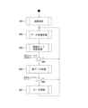
- FIG. 5 is a state transition diagram showing operation procedures of the battery pack 1 and the electrical equipment body 201 according to this embodiment.
- the transition diagram of FIG. 5 starts when the battery pack 1 is attached to the electrical equipment body 201 (step 101).
- the controller 50 of the battery pack 1 is activated (step 102).
- the control section 250 of the electrical equipment main body 201 is activated (step 282). Note that in a device (for example, an impact tool) that does not have a dedicated power switch in the electrical device main body 201, the control unit 250 is activated when the trigger switch 206 is first pulled.
- the controller 250 of the electrical equipment main body 201 transmits "equipment main body information" to the controller 50 of the battery pack 1 (step 283). That is, the battery pack 1 communicates with the main body of the electrical device 201 .
- the battery pack 1 communicates with the main body of the electrical device 201 .
- “sensor signal parameter output” is performed, and a “sensor output stop request” from the electrical device main body 201 or connection with the electrical device main body 201 is released ( By making a transition from a state in which communication is possible to a state in which communication is not possible, the "parameter output of the sensor signal” is stopped.
- the control unit 250 of the electrical equipment main body 201 transmits "equipment main body information" through the second signal terminal 36 and the second signal terminal 236 (step 283).
- the "equipment main body information” includes the model name of the electric equipment main body, information on the electric equipment main body necessary for utilizing sensor information, parameters necessary for controlling the electric equipment main body, and the like.
- the control section 50 of the battery pack 1 that has received the "equipment main body information” transmits the information of the mounted sensor among the sensors 61 to 69 to the control section 250 of the electric equipment main body 201 (step 104).
- the control unit 250 of the electric device main body 201 determines whether or not the attached battery pack 1 is compatible with the sensor control in the electric device main body 201 (step 284).
- step 285 the processing after step 285 is executed, and if the sensor control is not compatible, the subsequent steps are skipped, and the control unit 250 does not use the sensor information from the battery pack 1. Then, control of the electric equipment main body 201 is performed in the same manner as in the conventional art.
- the controller 250 of the electric device main body 201 determines that the operation mode currently set by the user 90 is a “sensor control mode” in which one or more of the sensors 61 to 69 mounted on the battery pack 1 are used. (step 285).
- the system stands by and does not execute the processing from step 286 onwards.
- the "sensor control mode” of step 285 is performed by the user 90 operating the "operation mode switch 267" provided on the electrical equipment body 201 (step 286).
- the operation mode switch may also be used as a switch (operation mode switch 267 in FIG. 3) for setting tightening strength, tightening mode, etc., or an operation panel on which various operation switches are arranged on the main body of the electric device 201.
- a new switch provided above may be used, and when the user 90 presses this change switch, the control unit 250 of the electrical equipment main body 201 transitions to the "sensor control mode" (step 288).
- the switch may be moved to the sensor control mode by performing a special operation such as pressing the switch for a long time.
- the control unit 250 of the electrical device body 201 that has shifted to the “sensor control mode” sends a sensor output request via the wired communication circuit 53, the second communication terminals 36 and 236, and the battery communication circuit 260. Then, an "information request signal (sensor output request signal)" is transmitted to the controller 50 of the battery pack 1 (step 290). Upon receiving the "information request signal (sensor output request signal)", the control unit 50 of the battery pack 1 switches to the "sensor output mode" (step 104). In the sensor output mode, the control unit 50 collects physical information using the mounted sensor among the sensors 61 to 69 and the target sensor whose output transmission is requested (step 106). .
- the battery pack 1 shown in FIG. 4 has sound sensors 63-66.
- control unit 50 of the battery pack 1 that has collected the physical information transmits the physical information together with the "battery pack information" to the control unit 250 of the electrical equipment body 201 (step 108).
- the physical information is transmitted to the control unit 250 via the wired communication circuit 53, the second communication terminals 36, 236, and the battery communication circuit 260.
- Acquisition timing and transmission timing of the physical information collected using the sensors 61-69 are then performed continuously or intermittently (for example, every clock time).
- the control unit 50 of the battery pack 1 continues to transmit the physical information collected using the sensors 61 to 69 to the electrical device main body 201 side, so the control unit 250 of the electrical device main body 201 Based on the transmitted physical information, control of the main body side of the electric device 201, in particular, rotation control of the motor 204, lighting, extinguishing, and illuminance control of the mode display LED 268 and the lighting LED 268 (see FIG. 3 for both). (step 293).
- Boxed steps 106 , 108 , and 293 of step 105 are executed when the battery pack 1 is removed from the main body of the electric device 201 or when the user 90 turns the operation mode switch 267 provided on the main body of the electric device 201 .
- the operation mode of the electrical equipment body 201 is continued until it is returned from the "sensor output mode” to the "normal mode".
- the control section 250 of the electrical equipment body 201 transmits an "information request stop signal (sensor output stop request signal)" to the control section 50 of the battery pack 1. (Step 295).
- An “information request stop signal (sensor output stop request signal)” is sent from the control unit 250 by wire through the battery communication circuit 260 , the second signal terminals 236 and 36 , and the wire communication circuit 53 .
- the control section 250 of the electrical equipment main body 201 returns to the "normal mode" in which the sensor output on the battery pack 1 side is not used.
- the control shown in FIG. 5 is terminated by turning off the power switch of the electrical device main body 201 or removing the battery pack 1 from the main body of the electrical device 201 (step 114).
- the controller 50 of the battery pack 1 collects physical information using information from the sensors 61-69.
- position information of the battery pack 1, inclination information of the battery pack 1, acceleration information of the battery pack 1, and the like can be considered.
- the control unit 50 stores the physical information, calculates the information of the battery pack 1 based on the physical information, and transmits the information to the control unit 250 of the electrical equipment body 201 (steps 107 to 109). .
- the control unit 250 of the electrical equipment body 201 controls the output of the load unit such as the motor 204 according to the received physical information and battery pack information (steps 291 and 292). This step 292 continues until the sensor output mode is canceled at step 294 in FIG.
- the control unit 250 of the electric device main body 201 terminates the sensor output mode (step 293), and transmits a control mode stop signal to the control unit 50 of the battery pack 1 (step 294).
- the control unit 50 of the battery pack 1 stops the control mode and shifts to the normal operation mode.
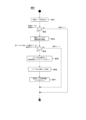
- FIG. 7 is a flow chart showing a schematic control procedure in the sensor output mode of the controller 50 of the battery pack 1 shown in FIG.
- the control unit 50 of the battery pack 1 mainly performs control in a loop of data reception processing 120 , sensor processing 140 and data transmission processing 150 .
- These loop controls are performed by pressing the operation mode switch 267 of the electrical equipment body 201 again and transmitting an "information request stop signal (sensor output stop request signal)" from the electrical equipment body 201 (step 295 in FIG. 5). can continue until
- FIG. 8 is a flow chart showing the detailed procedure of the data reception process 120 of FIG.
- the control unit 50 of the battery pack 1 determines whether or not communication data has been received from the outside (the control unit 250 of the electrical equipment body 201) (step 121). If there is reception, the control unit 50 performs reception processing of communication data (confirmation of command) (step 122).
- a command is prepared at the beginning of the communication data sent from the control unit 250 of the electrical equipment main body 201, and the control unit 50 of the battery pack 1 and the control unit 250 of the electrical equipment main body 201 communicate with this command type.
- Identify content For example, the data breakdown of communication data includes a command indicating a sensor output request at the beginning, followed by notification time (time interval for repeated transmission.
- sensor code output A designation code indicating any one of the sensors 61 to 69
- check data checksum
- the sensor code assigns binary bits in order to a plurality of sensors, assigns 1 to those that are used, and 0 to those that are not used. As an example, if the first and third sensors of the four sensors are used, the binary representation would be "0101".
- the control unit 50 determines whether or not the content of the command is "sensor output request" (step 123). If YES here, it is determined whether or not the checksum of the received data matches the checksum recreated by the control unit 50 (step 124).
- the code and notification time are extracted and updated and stored as sensor data in the control unit 50 of the battery pack 1 (step 125).
- the sensor code is used for power control of the sensor, and the notification time is used for transmitting the "parameter output of the sensor signal" in the "data transmission process” at regular intervals (step 126).
- the control unit 50 of the battery pack 1 transmits a response signal to the "sensor output request" signal to the electrical equipment body 201 (step 127).
- step 123 if the content of the command is "sensor output stop request processing” (step 128), the sensor code is cleared (step 129). As a result, the power supply for driving the sensors 61 to 69 of the battery pack 1 is turned off, and the transmission of the "parameter output of the sensor signal” is stopped. After that, the control unit 50 transmits a signal responding to the "sensor output stop request" to the electrical equipment body 201 (step 130). If No in step 128, other processing is performed and the process returns to step 121 (step 131). Note that other processing includes, for example, data processing of device main body information sent via communication, and information sent via communication (information to be received) includes the model name of the electrical device main body and sensor information. There are information on the main body of the electrical equipment necessary for utilization, parameters required for controlling the main body of the electrical equipment, and the like.
- step 141 the power state of each sensor 61 to 69 and the sensor code are collated.
- step 142 it is determined whether or not there is a change in the power state of the sensor (operational state due to power supply) (step 142).
- the power supply to each sensor 61 to 69 is controlled to be on or off according to the command sent from the electrical equipment main body 201 side (step 143). If it is determined in step 142 that there is no change in the power state of the sensor (operating state due to power supply), the process proceeds to step 144 .
- the controller 50 of the battery pack 1 determines whether or not there are any sensors 61 to 69 whose power is on (step 144). If there is a sensor 61 to 69 whose power is turned on, the detection data is obtained from the target sensor (any one of 61 to 69) (step 145). The acquired detection data is updated and held as data in the battery pack 1 (step 146). Next, when data acquisition from the necessary sensors 61 to 69 is completed, the control unit 50 sets the detection data acquisition completion flag of the sensor signal (step 147). This flag is used to count the time in the data transmission process and to enable or disable data transmission. If at step 144 there are no sensors 61-69 with power turned on, step 147 is followed.
- FIG. 10 is a flow chart showing the detailed procedure of the data transmission process 150 of FIG.
- data transmission is performed for each time period of the notification time set in the data reception process.
- the time count value is held as data in the battery pack, the time is counted, and the data is transmitted when the notification time has elapsed (the time count value is reset after transmission).
- the specific transmission conditions are (1) the parameters of the sensor signal are acquired. (The sensor signal detection data acquisition completion flag is set), (2) the device is connected (communication is possible), (3) the time count value matches the notification time (if not, the time count value is added).
- control unit 50 of the battery pack 1 determines whether or not the detection data acquisition completion flag of the sensor signal is set (step 151). If it is set here, the state of connection with the controller 250 of the electrical equipment body 201 is checked (step 152). If not, clear the time count value (step 163 ) and proceed to step 160 .
- the controller 50 of the battery pack 1 is electrically connected to the controller 250 of the electric device 201 and determines whether communication is possible (step 153). If it is determined in step 153 that the connection is not made, the sensor code is cleared (step 161), the time count value is cleared (step 163), and the process proceeds to step 160.
- step 153 it is determined whether or not the current time count value being counted matches the notification time (step 154).
- the control unit 50 sets the detected sensor data to the parameter of the sensor signal (step 155), and transmits it to the control unit 250 of the electrical equipment body 201 (step 155).
- This communication path goes through the wired communication circuit 53 , the second signal terminals 36 and 236 and the battery communication circuit 260 .
- the control unit 50 determines whether or not the notification time is 0 (step 157), clears the sensor code if it is 0 (step 158), and skips step 158 if it is not 0.
- control unit 50 clears the time count value (step 159) and clears the detection data acquisition completion flag of the sensor signal (step 160). If No at step 154 , that is, if the time count value does not match the notification time, the time count value is added by a predetermined unit (step 162 ), and the process proceeds to step 160 .
- the control unit 250 can perform various controls using additional sensor signals included in the battery pack 1 but not included in the electrical device main body 201 .
- the sensor signal output from the battery pack by the wired communication circuit of the battery pack (Fig. 1) is sent to the reception (input) via the wired communication circuit of the electrical device main body, and the electrical device main body transmits the sensor signal to the electrical device main body. Controls the output of the main unit.
- the control unit 50 of the battery pack 1 stops power supply to the sensors 61 to 69, and outputs sensor signals to the electric device main body side. Control not to send.
- the control unit 50 stops the power supply to the sensors 61 to 69 so as not to transmit sensor signals to the electrical equipment main body side.
- FIG. 11 is a block diagram showing the configuration of the electrical equipment body 301.
- the electric device main body 301 is a light having a mode (sound detection mode) in which a motor 304 controls an irradiation direction 314 of a light source 312 by an LED using the battery pack 1 as a power source so that it is directed in the direction of sound.
- An electric device main body (light device main body) 301 has a light section 303 that can rotate 360 degrees in the horizontal direction, and a light source 312 is provided in one direction of the light section 303 .
- the irradiation unit 310 has an LED (light emitting diode) as a light source 312 mounted on a substrate 311 and has a reflector 313 that guides the direction of light emission in one direction.
- the lighting device has the same structure as a known light device.
- the battery pack 1 is the same as the battery pack 1 shown in the first embodiment, has a connection terminal portion 30, and has a plurality (here, four) of sound sensors 63 to 66 (here, four) as sensors for collecting physical information. Reference numerals 65 and 66 refer to FIG. 12 described later).
- the electric device main body 301 has a mounting portion for mounting the battery pack 1, and the connecting terminal portion 320 is provided in the mounting portion.
- the electric power of the battery pack 1 is supplied to the control circuit board 345 of the electric device main body 301 by fitting the connection terminal portion 30 and the connection terminal portion 320 together.
- the main housing 302 of the electrical equipment main body 301 is provided with a power switch 330 for turning on the light source 312 and an operation mode switch 316 for setting whether or not to rotate the light unit 303 so as to follow the direction of sound. be done.
- Switching by the power switch 330 and the operation mode switch 316 is detected by a control circuit (especially a microcomputer not shown) mounted on the control circuit board 345, and the power supply to the light source 312 is turned on or off, or the power to the motor 304 is turned on or off. is supplied to rotate the light unit 303 .
- a control circuit especially a microcomputer not shown
- a motor 304 is a drive source for rotating a drive shaft 308 that supports the light unit 303, and is arranged so that the rotation shaft 305 is oriented vertically.
- the rotating shaft 305 is provided with a first gear 306 which is a spur gear.
- the lower end of the drive shaft 308 is rotatably supported by the main housing 302 and the other end is non-rotatably fixed to the light section 303 .
- a second gear 307 that is a large spur gear is fixed to the drive shaft 308 , and the rotational force of the motor 304 is transmitted to the drive shaft 308 in a reduced state by the meshing of the first gear 306 and the second gear 307 .
- a slip ring 309 is provided on the drive shaft 308 and below the second gear 307 to enable power supply from the control circuit board 345 to the light source 312 of the rotating light section 303 .
- the mounted motor 304 has a position detection means (not shown) capable of detecting its rotation angle, or the rotation position of the drive shaft 308 is discriminated by a microcomputer. It should be configured so that The mode can be switched by pressing the operation mode switch 316. There is a "normal mode” in which the light unit 303 is kept fixed without being rotated by the motor 304, and a mode in which the motor 304 is used to direct the sound in the direction from which the sound comes. It has a “sound detection mode” in which the light unit 303 is rotated by pressing. Note that this mode switching may be changed by transmitting a “control mode change request” from an external device such as a smartphone via the wireless communication circuit 55 of the battery pack 1 .
- FIG. 12 is a top view for explaining the operation of the light section 303 (see FIG. 11) of the electrical equipment main body 301.
- FIG. Four sound sensors 63 to 66 are provided at four corners near the upper surface of the battery pack 1 .
- the sensors 63-66 correspond to the "sensor section" of the present invention.
- the main housing 302 of the electrical equipment main body 301 does not rotate with respect to the battery pack 1 .
- a drive shaft 308 extends upward from the main housing 302 .
- the drive shaft 308 is rotatable by a motor 304 (see FIG. 11), and the light unit 303 (see FIG. 11) fixed to the top of the drive shaft 308 rotates.
- the control unit 350 (see FIG. 13 to be described later) of the electric device main body 301 performs data processing of sounds collected from the four sound sensors 63 to 66, and detects arrival of sound from a specific direction. Then, by driving the motor 304, the light irradiation direction 314 (see FIG. 11) can be controlled to be directed toward the estimated position 380 of the sound source. By controlling in this manner, it is possible to realize a light device that can emit light while following a work location when a worker performs work while moving at a work site or the like.
- FIG. 13 is a block diagram showing the circuit configuration of the electrical equipment body 301.
- the basic configuration is the same as the configuration shown in FIG.
- the electric device main body 301 is a light device
- the configuration of the light unit 303 is newly added.
- an LED control circuit 318 for lighting the LED 312 of the light unit 303 and a motor 304 for rotating the light unit 303 are added.
- the light unit 303 is provided with a light unit irradiation direction detection circuit 319 that detects the direction of the irradiation direction (how many degrees of rotation the angle is relative to the reference angle of 0 degrees in FIG. 12).
- the battery pack 1 that lights the LED 312 and supplies power to rotate the motor 304 has the same configuration as that of the first embodiment shown in FIG.
- the electric device main body 301 is provided with a first signal terminal 34 and a second signal terminal 36 as an input section, and is also provided with a positive terminal 32 and a negative terminal 37 . Illustrations of other configurations of the battery pack 1, other connection terminals (C+ terminal 31, third signal terminal 38), etc. are omitted.
- the electrical equipment main body 301 is entirely controlled by a control section 350 that operates with reference power supplied from a control power supply circuit 355 .
- the control unit 350 controls the rotation of the motor 304, receives outputs of various sensors (here, the sound sensors 63 to 66) from the control unit 50 side of the battery pack 1 via the wired communication circuit 360, and converts the received signals is processed, the rotation of the motor 304 is controlled according to the processing result, and the irradiation direction of the light unit 303 is controlled.
- the controller 350 corresponds to the "apparatus-side controller" of the present invention.
- the motor 304 is driven by a motor control circuit 351 under the control of the controller 350 .
- the motor 304 and the motor control circuit 351 used here are arbitrary, and can be controlled using, for example, a stepping motor.
- An LED control circuit 318 for lighting the light source 312 of the light unit 303 is controlled by the control unit 350 .
- the light section irradiation direction detection circuit 319 is configured using known position detection means, and outputs a signal indicating the rotation angle to the control section 350 .
- a microcomputer (not shown) of the control unit 350 controls the rotation of the motor 304 using the signal detected by the light unit irradiation direction detection circuit 319 and the physical information from the sensor received from the battery pack 1 .
- the switch operation detection circuit 317 detects ON/OFF of the operation mode switch 316 and outputs to the control unit 350 .
- a switch operation detection circuit 331 detects whether the power switch 330 is turned on or off, and outputs the result to the control unit 350 .
- FIG. 14 is a flow chart showing a schematic control procedure in the control section 350 of the electrical equipment main body 301 according to the second embodiment.
- the control related to the sensor output in the electrical equipment main body 301 is performed according to the procedure shown in FIG.
- the control unit 350 when the power switch 330 of the electrical equipment main body 301 is turned on, the control unit 350 is activated. At that time, the control unit 350 performs start-up processing (step 501).
- the control unit 350 performs reception processing for receiving physical information (here, “sound data”) acquired by the sensors 63 to 66 from the battery pack 1 (step 502).
- the current mode is the "sound detection mode”
- the process proceeds to step 505, and if the current mode is not the "sound detection mode”, the process returns to step 502 (step 504).
- the control section 350 processes the sensor information (here, sound data) transmitted from the battery pack 1 (step 505).
- the control unit 350 determines whether or not the "sound detection flag" has been set (step 506), and if it has been set, controls the motor (step 507), If not, the process returns from step 504 to step 502 .
- the control unit 350 of the electric device main body 301 performs data reception processing 502, sensor processing control mode switching processing 503, sound data processing 505 (if sound detection mode), motor control 507 (if sound is detected). 14 is repeated until the power switch 330 (see FIG. 11) is turned off.
- FIG. 15 is a flow chart showing the detailed procedure of the startup process 501 in FIG.
- the control unit 350 of the electrical equipment main body 301 reads the state flag of the control mode set from the built-in storage unit (not shown) at startup (step 511), and determines whether the state flag is the "sound detection mode”. It is determined whether or not (step 512). Here, in the case of the "sound detection mode", the "sensor output request processing" of steps 513 to 517 is performed. If the control mode is not the sound detection mode at step 511, the control section 350 controls the operation of the electrical equipment body 301 in the "normal mode".
- the connection state with the battery pack 1 is confirmed (step 513).
- the notification time and the sensor code are set in the "sensor output request” (step 515), and the "sensor output request ' is sent to the battery pack 1 (step 516), and the control mode change standby flag is set (step 517).
- the control mode change standby flag is a flag for checking whether a "sensor output request” or “sensor output stop request” has reached the battery pack 1, and is reset when a response arrives.
- step 514 if the battery pack 1 does not support the sound sensor, no request is made.
- FIG. 16 is a flow chart showing the detailed procedure of the data reception process 502 of FIG.
- the control unit 350 of the electrical device main body 301 determines whether or not data is received from the outside (battery pack 1) (step 521). If no data is received, skip the entire process of FIG. If data is received from the battery pack 1, the command sent is checked to identify the content of communication (step 522).
- the control unit 350 of the electrical equipment main body 301 determines whether the received command is a sensor signal parameter output (step 523). In the case of Yes at step 523, the control unit 350 of the electrical equipment body 301 performs "sampling data processing" (step 524).
- the control unit 350 of the electrical device main body 301 checks the received data, determines whether or not the checksums match, and updates the sampling data if the checksums match. As a result, the electric device body 301 holds the data obtained from the sound sensor as sampling data. Sampling data is retained for a certain period of time in the past.
- step 523 it is determined whether or not the received command is a response to the sensor output request (step 525).
- Yes "sound detection mode switching processing" is performed (step 526).
- the control unit 350 of the electric device main body 301 changes the control mode, clears the standby flag, clears the standby time count, clears the retransmission counter, and switches the control mode to the sound detection mode. Save the control mode and clear the sampling ring data.
- the standby time count is a value for counting a certain period of time when communication (transmission) is repeated when a desired response is not received within a certain period of time.
- step 525 it is determined whether or not the received command is a response to the sensor output stop request (step 527).
- Yes "normal mode switching processing” is performed (step 528).
- the control unit 350 of the electrical device main body 301 changes the control mode, clears the standby flag, clears the standby time count, clears the retransmission count, switches the control mode to the normal mode, to save.
- step 527 it is determined whether or not the received command is a control mode change request (step 529).
- other processing is performed.
- Other processing is, for example, data processing of information on the main body of electric equipment sent by communication. information on the main body of the electrical equipment, parameters necessary for controlling the main body of the electrical equipment, and the like.
- step 531 it is determined whether or not the specified mode is the normal mode (step 531).
- the normal mode "sensor output request processing” is performed (step 532).
- the control unit 350 of the electrical equipment main body 301 executes the same processes as steps 513 to 517 in FIG. If No in step 531, "sensor output stop request processing” is performed (step 533).
- the control unit 350 of the electrical device body 301 transmits a sensor output stop request and sets the control mode change standby flag.
- FIG. 17 is a flow chart showing the processing procedure when the operation mode switch 316 is pressed by the user.
- the control mode is changed when the operation mode switch 316 is pressed.
- the control unit 350 of the electrical equipment body 301 determines whether the operation mode switch 316 is pressed. (Step 541). If No in step 541 , the process proceeds to step 545 . If Yes at step 541, it is determined whether the current mode is normal mode or not (step 542).
- step 543 a sensor output request process is performed for the battery pack 1 (step 543).
- the control section 350 of the electrical equipment main body 301 executes the same processes as steps 513 to 517 in FIG. If No in step 542, that is, if the mode is not the normal mode, "sensor output stop request processing" is performed (step 544).
- the sensor output stop request process is the same as step 533 in FIG. 16, and the control unit 350 of the electrical equipment body 301 transmits the sensor output stop request and sets the control mode change standby flag.
- step 545 it is determined whether or not the control mode change standby flag is set (step 545). If Yes in step 545, that is, if the control mode change waiting flag is set, "communication waiting processing" is performed (step 546). If No in step 545, step 546 is skipped.
- FIG. 18 is a flow chart showing the detailed procedure of the communication standby process 546 of FIG.
- processing is performed until a response from the battery pack 1 reaches the control unit 350 of the electrical equipment main body 301 . If there is no response for a certain period of time, the sensor output request is resent to the battery pack 1, and if there is no response after resending the sensor output request a specified number of times, the transmission is stopped.
- the controller 350 of the electrical equipment main body 301 adds the standby time count (step 551).
- the control unit 350 determines whether or not the waiting time count has reached the retransmission waiting time (step 552). If the retransmission standby time has not been reached in step 552, the process of FIG.
- control unit 350 clears the waiting time count (step 554) and adds the number of retransmissions (step 555).
- the control unit 350 determines whether or not the number of retransmissions has reached a specified number of times. If not, the process of FIG. 18 is terminated. The number of times is cleared and the process of FIG. 18 is terminated (steps 557-559).
- FIG. 19 is a flow chart showing the detailed procedure of the sound data processing 505 in FIG.
- the controller 350 first confirms the sampling data received from the battery pack 1 (step 561), and stabilizes whether or not the sound volume exceeds a certain value (step 562). If the loudness of the sound exceeds the predetermined value, the control unit 350 sets a sound direction calculation flag (step 563), and skips to step 564 if it does not. Next, the control unit 350 determines whether the sound direction calculation flag is set or whether the sound detection flag remains set (step 564). If Yes in step 564, the control unit 350 uses the physical information from the four sound sensors 61 to 64 to calculate the direction of the sound from past sound data and subsequent sound data ( step 565).
- step 566 it is determined whether or not the direction of the sound can be estimated (step 566), and if it can be estimated, it is calculated as an angle A (see FIG. 21 described later) from the reference position (step 565).
- the control unit 350 sets the sound detection flag (step 568) and ends the processing of FIG. If the direction of the sound cannot be estimated in step 566, for example, if sampling of the sound data is insufficient, the process of FIG. 19 is terminated.
- FIG. 20 is a flow chart showing the detailed procedure of motor control 507 in FIG.
- the motor control 507 controls the light unit 303 to face the sound source by driving the motor 304 in the direction confirmed by the sound data processing 505 .
- the control section 350 of the electrical equipment main body 301 confirms the current direction in which the light section 303 is facing (step 571).
- control unit 350 determines whether motor 304 is in operation (step 572).
- step 572 determines whether the irradiation direction of the light unit 303 is directed toward the sound source direction, that is, whether the light arrival direction reaches the target direction (sound source direction) It is determined whether or not (step 573).
- step 573 If it is in the direction of the sound source in step 573, rotation of the motor 304 is stopped (step 574), the sound direction calculation flag and sound detection flag are cleared, and the processing of FIG. 20 is terminated (step 575). Also, in step 573, if the irradiation direction of the light unit 303 has not reached the target direction, the process of FIG. 20 is terminated and the process returns to step 506 of FIG.
- the sound direction calculation flag is a flag that is set when a threshold (loudness) for determining that a sound has been heard is exceeded, and is used to enter the flow for calculating the direction of sound.
- the sound detection flag is a flag that is set when the estimation of the sound direction is completed, and is used to enter the motor operation flow.
- step 572 If the motor is not operating in step 572 (if the motor 304 is not operating), the control section 350 calculates the rotation angle B° of the light section 303 from the reference position (step 576). Next, the control unit 350 determines whether the angle A (°) of the estimated position of the sound source is equal to the rotation angle B (°) (step 577). is cleared, and the process of FIG. 20 ends (step 578). In step 577, if A ⁇ B, the control unit 350 calculates the motor rotation speed and the direction of the sound source (step 579), sets the calculated direction as the target direction (step 580), and starts the motor 304. (step 581) and returns to step 506 in FIG.
- FIG. 21 is a top view for explaining the change of the irradiation angle of the electrical equipment main body 301 of FIG. 11.
- FIG. 14 to 20 using the outputs of the four sound sensors 63 to 66 mounted on the battery pack 1, the control unit 350 sets the rotation angle of the light unit 303 to the reference position (0 degree). , the light is directed in a direction rotated clockwise by B°.
- a "sensor output request (information request signal, sensor output request signal)" is sent to the battery pack 1, and the "sensor signal parameter output (physical information/battery
- the controller 350 controls the rotation of the motor 304 in accordance with the pack information or operating conditions.
- the irradiation direction is fixed at the time of switching or returns to the initial position.
- FIG. FIG. 22(A) is a left side view of the electric device main body 401
- (B) is the attitude of the battery pack 1 in the state of (A).
- the directions of the Y-axis and Z-axis shown in (B) are the directions with the battery pack 1 as a reference.
- the battery pack 1 can be attached to the battery pack attachment portion 402c by moving it relative to the electric device body 401 from the rear to the front in the direction indicated by the arrow. In other words, in FIGS.
- the mounting direction of the battery pack 1 with respect to the electrical equipment main body 401 is the front direction (the direction of the ⁇ Y axis).
- the information on the electrical equipment main body 401 includes the mounting direction of the battery pack 1 .
- One acceleration sensor may be provided in the battery pack 1, and in this embodiment, it is provided at the position of the sensor 64 in FIG.
- the electrical equipment main body 401 includes a base 410 that is placed on and slides on the object to be cut, a saw blade 405 that protrudes from an opening provided in the base 410 to the bottom surface of the base, a motor 404 that rotates the saw blade, and a motor 404 that rotates the saw blade. It has a handle portion 403 provided on the top of the housing that accommodates the .
- the handle portion 403 is provided with a trigger lever 406 for turning on the rotation of the motor 404 . Since the configuration of the electrical equipment main body 401 is well known, detailed description thereof will be omitted.
- the battery pack 1 Since the battery pack 1 is mounted in the electrical equipment main body in a horizontal state, when the electrical equipment main body 401 is in a horizontal state as shown in (A), the battery pack 1 is also in a horizontal state.
- the electrical equipment main body (circular saw) 401 is configured such that the amount of projection of the saw blade from below the base 410 (so-called depth of cut) can be changed. That is, it is configured such that the angle of the electrical device main body with respect to the base 410 can be changed.
- FIG. 22A shows a state in which the saw blade protrudes from the base 410 at its maximum.
- the electric device main body is in a state within the permitted operation range 480 (example of identification information) in FIG. 22(C). Therefore, within the range where the cutting depth can be adjusted, the electric device main body 401 is in a state within the operation permission range 480, and the cutting work can be performed.
- whether or not it is “within the operation allowable range 480” can be determined by the magnitude of the Y component and Z component in the output of the acceleration sensor 64, and ⁇ 0.87g ⁇ Y ⁇ 0.5g and Z >0 is determined to be within the operation allowable range.
- the dotted line on the horizontal axis is the absolute Y-axis direction (one direction passing through the horizontal plane)
- the dotted line on the vertical axis is the absolute Z-axis direction (one direction passing through the extension plane).
- the control unit 50 of the battery pack 1 receives information input from the acceleration sensor 64 (physical information including the attitude and orientation of the electrical device main body), or the battery pack that allows the electrical device main body 401 to operate based on the information.
- Information (battery pack information related to physical information) is output to the control unit 450 (corresponding to the control unit 250 in FIG. 3 and the control unit 350 in FIG. 13) of the electrical device main body 401 . The worker can continue working on the electrical device main body 401 thereafter.
- FIG. 23 shows a state in which the front side of the electric equipment main body 401 is turned upward by about 45 degrees from the state of FIG. 22(A).
- FIG. 4 is a plan view, and (B) shows the attitude of the battery pack 1 when the electric device main body 401 is in the state of (A). 22, the battery pack 1 in this posture assumes the same posture as shown in (B) together with the electric device main body 401. Therefore, the acceleration sensor 64 is affected by the gravitational acceleration. is 0.64 g in the Z-axis direction and 0.64 g in the Y-axis direction as shown in (C). This is outside the permitted operation range 480 described above.
- the control unit 50 of the battery pack 1 controls this posture information (physical information including the posture and orientation of the electrical device body), or battery pack information (physical information) prohibiting the operation of the electrical device body 401 based on the posture information.
- Battery pack information related to the information such as a stop signal, is output to the control unit 450 (not shown) of the electrical device main body 401 . As a result, work on the electrical device body 401 is prohibited (stopped).
- FIG. 24 shows a state in which the posture of the electrical equipment main body 401 is reversed and rotated about 150 degrees from the state shown in FIG. 22(A). This state corresponds to a working state in which an operator uses a circular saw to cut tree branches or cut a ceiling tree from below.
- FIG. 24(A) is a left side view of the electric device main body 401
- (B) is the attitude of the battery pack 1 in the state of (A).
- the battery pack 1 with the electrical equipment main body 401 in the posture of FIG. 24A is affected by the gravitational acceleration, and the detection value of the acceleration sensor 64 in the Z-axis direction is -0.87 g and in the Y-axis direction is 0.87 g. 5 g.
- the detected value in the Z-axis direction is a negative value because the acceleration sensor 64 is upside down. This is outside the permitted operation range 480 described above.
- the control unit 50 of the battery pack 1 controls this posture information (physical information including the posture and orientation of the electrical device body), or battery pack information (physical information) prohibiting the operation of the electrical device body 401 based on the posture information.
- Battery pack information related to the information such as a stop signal, is output to the control unit 250 of the electrical equipment main body 401 . As a result, work on the electrical device body 401 is prohibited (stopped).
- the control unit 50 of the battery pack 1 outputs posture information (physical information) input from the acceleration sensor 64 to the control unit 450 of the electric device body 401, or outputs the posture information Control for outputting the battery pack information (operation permission signal and operation prohibition signal of the electrical device main body 401) to the control unit 450 of the electrical device main body 401 has been described. With this control, it is possible to effectively prohibit the work of operating the circular saw in an inappropriate posture using the battery pack 1 with the sensor. 22 to 24, the detection results in the X-axis direction are not referred to for the sake of simplification of the explanation, but the detection results of all the three axes of the acceleration sensor 64, ie, the X-axis, the Y-axis, and the Z-axis.
- Further advanced control may be performed by referring to the posture determination. Further, the operation of the electric device main body 401 may be controlled using not only the acceleration sensor 64 but also the output of any one of the other sensors 63 , 65 and 66 .
- the operation of the electric device main body 401 may be controlled using not only the acceleration sensor 64 but also the output of any one of the other sensors 63 , 65 and 66 .
- the control unit of the battery pack 1 outputs the physical information input from the acceleration sensor 64 to the electrical device main body 401. Also good.
- the control section 450 of the electrical device main body 401 may control the operation based on the information obtained from this physical information and the mounting direction information of its own battery pack.
- the configuration in which the battery pack 1 slides in the horizontal direction (front-rear direction) with respect to the electric device main body 401 is described.
- a configuration in which the mounting direction of the battery pack 1 with respect to the electric device main body 601 (circular saw main body) is different will be described.
- the battery pack 1 is slid vertically (from top to bottom) and attached to the main body.
- FIG. 25 shows a case where the electrical device main body 601 is in a horizontal state
- (A) is a left side view of the electrical device 601
- (B) is the battery pack 1 in the state of (A).
- the battery pack 1 is, for example, vertically attached to the battery pack attachment portion 602c of the electrical equipment main body 601, and when the electrical equipment main body 601 is in the horizontal state as shown in (A), the battery pack 1 is in the vertical state.
- Information (physical information) is output to the control unit 650 of the electrical device main body 601, or battery pack information (for example, an operation permission signal of the electrical device main body 601) regarding the attitude information is sent to the control unit 650 of the electrical device main body 601.
- Output In FIG. 25C, the dotted line on the horizontal axis is the absolute Z-axis direction (one direction passing through the horizontal plane), and the dotted line on the vertical axis is the absolute Y-axis direction (one direction passing through the extension plane). .
- FIG. 26 shows a state in which the posture of the front side of the electric device main body 601 is turned upward by about 45 degrees from the state shown in FIG. 25(A).
- FIG. 26(A) is a left side view of the electric device main body 601
- (B) is the posture of the battery pack 1 in the state of (A).
- the battery pack 1 in this case has the detection values of the acceleration sensor 64 in the Y-axis direction and the Z-axis direction of -0 in the Y-axis direction as shown in (C). .64g, and 0.64g in the Z-axis direction. Since this falls outside the above-described permitted operation range 680, the control unit 50 of the battery pack 1 uses the attitude information (physical information) input from the acceleration sensor 64 as the electric device. It outputs to the control unit 250 of the main body 601 , or outputs battery pack information (for example, an operation prohibition signal for the electric device main body 601 ) related to the posture information to the control unit 650 of the electric device main body 601
- FIG. 27 shows a state in which the posture of the electrical equipment main body is reversed and rotated by about 150 degrees from the state shown in FIG. 25(A). This state corresponds to a working state in which an operator uses a circular saw to cut a tree branch from below or a ceiling tree from below.
- FIG. 27(A) is a left side view of the electric device main body 601
- (B) is the attitude of the battery pack 1 in the state of (A).
- the battery pack 1 in the posture shown in FIG. 27A is affected by gravitational acceleration, and the detection value of the acceleration sensor 64 in the Y-axis direction is 0.87 g, and the detection value in the Z-axis direction is 0.5 g. .
- the detected value in the Y-axis direction is a positive value because the acceleration sensor 64 is upside down. This is outside the allowable operation range 680 described above.
- Posture information (physical information) input from the acceleration sensor 64 is output to the control unit 250 of the electrical device main body 601, or battery pack information related to the posture information (for example, an operation prohibition signal of the electrical device main body 601) is electrically transmitted. It outputs to the control unit 250 of the device body 601 .
- the control of the control section 650 (corresponding to 250 in FIG. 3) of the electrical equipment main body 601 will be described using a flowchart 700 in FIG.
- the control unit is activated to turn on the electrical equipment (step 701).
- the controller 650 communicates with the battery pack 1 via a battery communication circuit (corresponding to 260 in FIG. 3) and a wired communication circuit (corresponding to 261 in FIG. 3) (not shown) (step 702).
- the control unit of the electrical device main body 601 receives battery pack information including information on whether the battery pack 1 is a sensor-compatible model and information detected by the acceleration sensor 64 of the battery pack 1 from the battery pack 1. (corresponding to step 104 in FIG. 5), the information of the electric equipment main body 601, for example, the model name and control parameter information of itself is transmitted to the battery pack 1 (corresponding to step 283 in FIG. 5).
- the control unit 650 executes sensor signal processing based on physical information (orientation information) obtained from the acceleration sensor 64 of the battery pack 1. (step 704).
- This sensor signal processing as described with reference to FIGS. sets (turns on) an operation prohibition flag (step 704).
- Control unit 650 sets operation permission range 680 based on the mounting direction of battery pack 1 with respect to electric device main body 601 of itself. If it is within the operation permission range 680, the operation permission flag may be set.
- the operation prohibition flag is reset (turned off) (step 705).
- step 706 when the operation prohibition flag is set (Yes in step 706), the control unit 650 prohibits the driving of the electric device main body and notifies the operator of the prohibition of operation by, for example, an LED (step 707). End (step 710).
- the operation prohibition flag is not set (No in step 706), it is determined whether the trigger switch is operated to execute normal operation (step 708). If so (Yes in step 708), a process for operating the electrical equipment main body (motor) is executed (step 709). If the trigger switch has not been operated (No in step 708), the control ends (step 710). Finally, the control unit 650 determines whether or not the power OFF flag is turned on (step 711). Turn off. If the power OFF flag is not turned off at step 711 (No at step 711 ), the process returns to step 702 .
- the control procedure has been described with the configuration in which the battery pack 1 is vertically mounted on the electrical equipment main body 601 .
- the mounting direction of the battery pack 1 with respect to the electric equipment main body is not limited to this, and the electric equipment main body 401 configured to be mounted in the front-rear direction like the third embodiment shown in FIGS. can be applied in the same manner, and can also be applied in the same manner to an electrical equipment main body in which the battery pack 1 is installed in the left-right direction or in the oblique direction.
- the number of battery packs 1 that can be attached to the electrical device main bodies 401 and 601 at the same time is not limited to one, and may be plural.
- the physical information of the acceleration sensor in each battery pack or the battery pack information related to the physical information is transmitted to the electric device main bodies 401 and 601. If configured to transmit, the control unit of the electric device main body 401 or 601 can control its own operation based on the sensor information and information that can be detected by itself (for example, mounting direction information of the battery pack 1).
- FIG. 29 is an external view of a specific device as the electrical device main body 801, showing an example of a radio here.
- FIG. 29(A) is a perspective view of the electric device main body 801 as seen from the front upper side.
- the electrical device main body 801 uses the battery pack 1 as a power source and automatically adjusts the volume (output value) output from the speaker 806 in accordance with the volume of the surrounding sound (automatic volume adjustment mode).
- the fifth embodiment is not limited to radios, and can be widely applied to televisions whose volume can be adjusted, and other audio equipment.
- a radio main body 801 as an electric device main body includes a handle 803 held by a user, an operation panel 805 operated by the user and having a power button, a volume adjustment button, a mode switching button, and a channel switching button, and a volume display and a channel display. and a speaker 806 provided on the front surface of the main body.
- FIG. 29B is a perspective view of the electric device main body 801 viewed from the rear and lower side, and a battery pack mounting portion 810 for mounting the battery pack 1 is provided on the back side of the housing 802 of the radio main body 801 .
- the shape of the battery pack mounting portion 810 is the same as (compatible with) the battery pack mounting portion 202c shown in FIG.
- a terminal portion (body-side terminal portion) is provided between them.
- An AC adapter connection portion 811 for connecting a connector of an AC adapter (not shown) is provided near the battery pack mounting portion 810 .
- FIG. 30 is a block diagram showing the configuration of the electrical equipment main body 801. As shown in FIG. Since the configuration of the battery pack 1 shown on the left side is the same as the configuration shown in FIG. 3, the same reference numerals are used to omit repeated description.
- the electric device main body 801 is a radio, and the radio waves received by the AM antenna 821 and the FM antenna 822 are detected by the DSP radio IC 820 , amplified by the amplifier circuit 823 , and output by the speaker 806 as sound.
- the electric device main body 801 includes a control section 850 that communicates with the control section 50 included in the battery pack 1 .
- the electrical equipment body 801 is provided with a positive input terminal 832 and a negative input terminal 837, which are connected to the positive terminal 32 and the negative terminal 37 of the battery pack 1, respectively.
- the battery pack 1 is provided with a positive electrode terminal for charging (so-called C+ terminal) as a terminal for electric power, but the illustration is omitted here.
- the electric device main body 801 has a first signal terminal (T terminal) 834, a second signal terminal (LS terminal) 836, a third A signal terminal (LD terminal) 838 is provided.
- a control signal input circuit 861 is connected to the third signal terminal (LD terminal) 838 .
- the control signal input circuit 861 determines the signal transmitted from the battery pack 1 side and outputs it to the control section 850 .
- the battery communication circuit 860 is connected to a first signal terminal (T terminal) 834 and a second signal terminal (LS terminal) 836, and uses the signal terminals of the LS terminals 36, 836 and the T terminals 34, 834 to communicate with the battery pack 1. Two-way wired communication with the wired communication circuit 53 is performed.
- DSP radio IC 820 incorporates all necessary functions for receiving AM and FM radio in one IC by digitally calculating analog signals input from AM antenna 821 and FM antenna 822 using a processor. A commercially available product can be used. DSP radio IC 820 outputs an audio signal to amplifier circuit 823 .
- the power button 856 is operated by the user, drive power is supplied from the control power supply circuit 855 to the control unit 850, the DSP radio IC 820, the amplifier circuit 823, etc., and the electrical equipment main body 801 is activated.
- the self-holding circuit 859 continuously outputs a signal for keeping the control power supply circuit 855 on, and power supply from the control power supply circuit 855 to the control unit 850 is maintained.
- the volume adjustment button 831 is an operation button for adjusting the volume of the sound output from the speaker 806, and has two buttons, for example, a + button (increase volume) and a - button (decrease volume). Configured.
- the mode switching button 832 is operated when switching between the automatic volume adjustment mode (first mode) and the normal mode (second mode) according to this embodiment.
- the control unit 850 adjusts the volume according to the user's operation of the volume adjustment button (adjustment unit) 831 in the "normal mode", and obtains the volume from a sensor such as a microphone provided in the battery pack 1 in the "automatic volume adjustment mode".
- a channel switching button 833 is a switching button for switching the broadcast channel set in the storage device of the control unit 850 .
- a display unit 804 is a known dot matrix display means such as a liquid crystal display device, and visibly displays various information such as channel display, volume display, and mode display of "normal mode” or "volume automatic adjustment mode". do.
- FIG. 31 is a flowchart (900) showing the operation of the control unit 850.
- the controller 850 executes start-up processing (step 901).
- the control unit 850 executes processing of data and operations received via the battery communication circuit 860, the control signal input circuit 861, and the buttons of the operation panel 805 (see FIG. 30) (step 902), and performs control mode switching processing. (step 903).
- step 904 volume control is performed to automatically adjust the volume according to the ambient sound (step 905), and return to step 902;
- the control unit 850 adjusts the volume set according to the operation of the volume adjustment button 831, and step 902 back to
- the control unit 850 When the “volume automatic adjustment mode” is set, the control unit 850 outputs the output volume from the speaker 806 according to the ambient sound (external volume) received by the sound sensors 63 to 66 (the amplification factor of the amplifier circuit 823). automatically adjust.
- the external sound pressure level obtained from the sound sensors 63 to 66 of the battery pack 1 is calculated. In this case, it is preferable to perform auditory correction, adjust the magnitude for each frequency, and add them up for calculation. If the calculated sound pressure level of the external volume is less than the threshold A, the control unit 850 sets the output volume to W (step 952). is set to X (step 953).
- the sound pressure level to be compared with the threshold value A can be determined by a method of comparing the peak value of the sound pressure, a method of comparing the average value, a method of comparing the sound pressure value weighted by a specific frequency, time, etc., as appropriate. should be set. Furthermore, if the external volume is greater than or equal to the threshold B and less than the threshold C, the controller 850 sets the output volume to Y (step 954), and if the external volume is greater than or equal to the threshold C, sets the output volume to Z. (step 955).
- the output volume has a relationship of W ⁇ X ⁇ Y ⁇ Z.
- the radio 801 shown in FIG. 29 also has a variable mechanism that automatically rotates the speaker 806 so that it faces the direction in which the external sound is generated or the direction in which the sound is loud. You can add it.
- the variable parts and variable settings of the electrical equipment main body side shown in the fifth embodiment may be adjusted.
- the illuminance of the light 301 may be automatically adjusted in accordance with not only the irradiation direction but also the ambient brightness.
- a fan driven by the battery pack 1 can also be used as the main body of the electrical equipment. The adjustment may be performed automatically, or the air volume of the fan may be automatically adjusted according to the ambient temperature measured by the temperature sensor provided in the battery pack 1 .
- the setting of the sound detection mode in FIG. 21 may be configured to be changed by a "control mode change request" from an external device (for example, a smart phone) via wireless communication of the battery pack.
- an external device for example, a smart phone
- Wired communication circuit 55... Wireless communication Circuit 56 Antenna 61 to 69 Sensor 80 Display 81 Display window 85 Switch button 90 User 120 Data reception process 140 Sensor process 150 Data transmission process 201 Electrical equipment (body) 202 Housing 202a Body 202b Handle 202c Battery pack mounting part 204 Motor 204a Rotor 204b Stator 206 Trigger switch 206a Trigger lever , 207 forward/reverse switching lever 208 tip tool holding portion 209 tip tool 211a, 211b rail portion 212 curved portion 214 protrusion 215 terminal portion 215a vertical surface 215b horizontal surface , 232...positive input terminal, 234...first signal terminal (T terminal), 235...fourth signal terminal (V terminal), 236...second signal terminal (LS terminal), 237...negative input terminal, 238...third SIGNAL TERMINAL (LD TERMINAL) 250 (main body side) control unit 251 inverter control circuit 252 inverter circuit 253 shunt resistor 254 capacitor 255 control power supply circuit 256 current detection circuit 257
- Electric apparatus main body 302... Main housing, 303... Light part, 304... Motor, 305... Rotary shaft, 306... First gear, 307... Second gear, 308... Drive shaft..., 309... Slip ring, 310... Irradiation unit 311... Substrate 312... Light source (LED) 313... Reflector 314... (Light) irradiation direction 316... Operation mode switch 317... Switch operation detection circuit 318... LED control circuit 319...
Abstract
電池パック側に1つ以上のセンサを設け、電池パック側から電気機器本体側へセンサ情報を送信することで、電気機器本体201の制御部250がセンサ情報を用いた制御を行えるようにした。 電池パック1に外的要因に起因する物理的情報を収集して出力する複数のセンサ61~69を設け、電池パック1の制御部50はセンサ61~69によって検出された信号をそのまま、又は、集計してから電気機器本体201側に送信する。電気機器本体201の制御部250は、信号端子を介して取得したセンサ情報を用いて電気機器本体201の動作を制御する。
Description
本発明は、本発明は電池パック及び電気機器に関する。
電池パックを電源とした携帯型の電気機器が広く普及している。このような周知の技術は、例えば特許文献1に開示されている。特許文献1には、電池パックと電気機器本体との間に装着されるアダプタであって、傾きセンサ、制御部及び信号出力端子を備えたアダプタが開示されている。特許文献1のアダプタは、傾きセンサによって検知された傾きが所定の値より大きいことを検知した場合に、アダプタの制御部が、信号出力端子から電気機器本体に停止信号を出力して、電池パックから電気機器本体への電力供給を遮断するように構成されている。特許文献1に開示されたアダプタは、電池パックと電気機器本体の間に装着されるものであるため、電気機器が全体として大きくなり、アダプタを装着しない場合と比べて作業性に劣るものであった。そこで、センサを電池パックに設けることで電気機器の大型化を抑えた構成が特許文献2に記載されている。
特許文献2には、電池パックに加速度センサと制御部を設け、電池パック側の制御部によってインパクト工具本体による打撃を検知し、制御部が電池パック側に設けられたスイッチング素子をオフにすることで、電池パックからインパクト工具本体への電力供給を遮断するよう構成されたインパクト工具が開示されている。
しかしながら、特許文献2のインパクト工具は、電池パックの判断により電池パックの内部で電力供給を遮断するものである。よって、大きな打撃力を発生するインパクト工具に接続された場合は打撃を検知できるが、小さな打撃力を発生するインパクト工具に接続された場合は打撃を検知できないといった問題が生じ、汎用性が低いと考えられる。汎用性を高くするために、接続されるインパクト工具等の電気機器本体から出力される機器情報に応じた制御をすることが有用であると考えられる。また、電池パックは様々な電気機器本体に接続されて使用されるため、打撃検知以外の情報を検出できるセンサを設ければ利便性が向上する。
本発明は上記背景に鑑みてなされたもので、その目的は、電気機器の大型化を抑制しつつ、接続される電気機器本体から出力される機器情報に応じた制御を可能にした電池パック及びそれを用いた電気機器を提供することである。
本発明の他の目的は、利便性を向上させた電池パック及びそれを用いた電気機器を提供することである。
本発明の他の目的は、電池パックに多様なセンサを設け、電池パックからセンサ情報を電気機器本体側に送出することによって、電気機器本体の制御部がセンサ情報を用いた制御を行えるようにした電池パック及びそれを用いた電気機器を提供することにある。
本発明の他の目的は、利便性を向上させた電池パック及びそれを用いた電気機器を提供することである。
本発明の他の目的は、電池パックに多様なセンサを設け、電池パックからセンサ情報を電気機器本体側に送出することによって、電気機器本体の制御部がセンサ情報を用いた制御を行えるようにした電池パック及びそれを用いた電気機器を提供することにある。
本願において開示される発明のうち代表的な特徴を説明すれば次のとおりである。
本発明の一つの特徴によれば、電池パックの外的要因に起因する物理的情報を収集して出力するよう構成されたセンサ部と、センサ部に接続される電池パック制御部を有する電池パックにおいて、電池パック制御部は、センサ部から入力された物理的情報を電気機器本体に出力するか、又は、物理的情報に関連する電池パック情報を生成して電気機器本体に出力するように構成した。また、センサ部から入力された物理的情報に応じた制御を実行するよう構成した。ここで、外的要因に起因する物理的情報には、電池パックの位置、姿勢、又は加速度に関する情報を含む。電池パック制御部は、電気機器本体の機器側制御部と通信可能に構成される。
本発明の一つの特徴によれば、電池パックの外的要因に起因する物理的情報を収集して出力するよう構成されたセンサ部と、センサ部に接続される電池パック制御部を有する電池パックにおいて、電池パック制御部は、センサ部から入力された物理的情報を電気機器本体に出力するか、又は、物理的情報に関連する電池パック情報を生成して電気機器本体に出力するように構成した。また、センサ部から入力された物理的情報に応じた制御を実行するよう構成した。ここで、外的要因に起因する物理的情報には、電池パックの位置、姿勢、又は加速度に関する情報を含む。電池パック制御部は、電気機器本体の機器側制御部と通信可能に構成される。
本発明の他の特徴によれば、電池パックは、電気機器本体と電気的な接続を可能とする金属製の接続端子を複数有し、接続端子の一部を用いて電気機器本体との有線による通信を行う。電池パック制御部は、センサ部によって検出された物理的情報に応じて電気機器本体の動作条件を変更可能に構成される。また、電池パック制御部は、接続された電気機器本体に応じて電気機器本体の動作条件を変更可能に構成される。このような電池パックと、電池パックが装着可能な電池パック装着部と、電池パックによって駆動する負荷部と、を有する電気機器本体と、を備えた電気機器を実現した。
本発明のさらに他の特徴によれば、機器側制御部を有する電気機器本体に装着可能な電池パックは、電池パックの外的要因に起因する物理的情報を収集して出力するよう構成されたセンサ部と、センサ部に接続されると共に機器側制御部から出力される機器情報が入力される電池パック側制御部と、を有して構成される。電池パック側制御部は、機器側制御部からセンサ部の出力信号を要求された場合には、電気機器本体を制御する信号を電気機器本体に送信し、機器側制御部からセンサ部の出力信号を要求されない場合には、センサ部の出力信号を電気機器本体に送信するよう構成される。
本発明の他の特徴によれば、電気機器本体は機器側制御部を有し、機器側制御部は、電池パック装着部に対する電池パックの装着方向に関する情報と、電池パックから出力された物理的情報又は電池パック情報と、に基づいて負荷部を制御する。機器側制御部は、物理的情報又は電池パック情報が装着方向に関する情報と一致しない場合には負荷部の駆動を禁止する。電気機器に対する電池パックの装着方向に関する情報は、電気機器本体が正常に載置された状態における電池パックの装着方向を基準にした動作許可範囲を含み、機器側制御部は、物理的情報又は電池パック情報が動作許可範囲から外れている場合には負荷部の駆動を禁止する。
本発明の他の特徴によれば、電気機器本体は、光又は音を出力可能且つ回動可能な出力部と、出力部の回動を制御する機器側制御部と、を有し、物理的情報又は電池パック情報は、電気機器本体の周囲に発生する音に関する情報を含み、機器側制御部は音に関する情報に基づいて、出力部の光又は音の出力方向又は出力値を変更するよう構成される。また、電気機器は、ユーザによって操作され、出力部の出力を調整する調整部を備え、機器側制御部は、音に関する情報に基づいて出力部を制御する第1モードと、調整部の操作に基づいて出力部を制御する第2モードと、の一方によって出力部を制御するよう構成される。
本発明によれば、電気機器の大型化を抑制しつつ、接続される電気機器本体から出力される機器情報に応じた制御を可能にした電池パック及び電気機器を提供することができる。また、利便性を向上させた電池パック及びそれを用いた電気機器を提供することができる。また、本発明によれば、電池パックに多様なセンサを設け、電池パックからセンサ情報を電気機器本体側に送出することによって、電気機器本体の制御部がセンサ情報を用いた制御を行えるようにした電池パック及びそれを用いた電気機器を提供することができる。
以下、本発明の実施例を図面に基づいて説明する。なお、以下の図において、同一の部分には同一の符号を付し、繰り返しの説明は省略する。また、本明細書においては、前後左右、上下の方向は図中に示す方向であるとして説明する。
図1は本発明の実施例に係る電気機器201の本体部(以降、電気機器本体201と称す場合もある)と電池パック1の斜視図である。電気機器本体201として、インパクト工具の例を示している。電気機器201の本体部は、着脱式の電池パック1を電源とし、モータによる回転駆動力を用いて先端工具209を駆動することにより締め付け作業を行う。電気機器201の本体部は、外形を形成する外枠たるハウジング202を備える。ハウジング202は、図示しないモータや動力伝達機構を収容する胴体部202aと、胴体部202aから下方に延びるハンドル部202bと、ハンドル部202bの下側に形成される電池パック装着部202cにより構成される。ハンドル部202bの一部には、トリガ状のトリガスイッチ206(符号は後述の図3参照)が設けられ、トリガスイッチ206のトリガレバー206aが突出する。トリガスイッチ206の上方にはモータの回転方向を切り替えるための正逆切替レバー207が設けられる。ハウジング202の前方側には出力軸たるアンビル(図では見えない)が設けられ、アンビルの先端には先端工具209を装着するための先端工具保持部208が設けられる。ここでは先端工具209としてプラスのドライバービットが装着されている。
電池パック装着部202cには、左右両側の内壁部分に前後方向に平行に延びる溝やレールを含むレール部211a、211bが形成され、それらの間にターミナル部(本体側端子部)215が設けられる。ターミナル部215は、合成樹脂等の不導体材料の一体成形により製造され、そこに金属製の複数の端子、例えば正極入力端子232、第1信号端子234、第2信号端子236、負極入力端子237、第3信号端子238、第4信号端子235を有する。ターミナル部215は、合成樹脂の成形によって複数の金属端子(232、234~238)を鋳込むことにより製造され、装着方向(前後方向)の突き当て面となる垂直面215aと、水平面215bを有するように形成される。
ターミナル部215は、左右分割式の電池パック装着部202cの開口部分(図では見えない)に挟持されるようにして固定される。ターミナル部215の水平面215bは電池パック1の装着時に、電池パック1側の上段面13と近接、対向する面となる。水平面215bの前方側には、電池パック1の隆起部15と当接する湾曲部212が形成され、湾曲部212の左右中央付近には突起部214が形成される。
電池パック1は、対応する電気機器201の本体部に対して着脱式であり、複数本の電池セルを合成樹脂製のケース内に収容する。電池パック1の上部には、電気機器201の本体部に装着するためのレール溝18a、18b(図1では見えない)と、電気機器201の本体部との電気的な接続を実現するためのスロット部20と、スロット部20の内側部分に配置される接続端子群(図3にて後述)と、電気機器201の本体部との装着状態を維持又は解除するためのラッチ機構(ラッチ部)が設けられる。ラッチ機構は、ラッチボタン16a、16bと、ラッチボタン16a、16bと連動して移動する係止爪17a、17b(図1では見えない)を含んで構成される。上ケース(第1ケース)10の側面には、2本のレール溝18a、18b(図1では見えない)が形成される。レール溝18a、18bは、長手方向が電池パック1の装着方向と平行に形成される。
電池パック1は、内部に複数の電池セルを収容し、直流の定格電圧(例えば18V)が出力できる。電池パック1の電圧や、用いられる電池セルの種類は任意である。尚、電池パック1の出力電圧を、低/高電圧の切り替え式に構成しても良い。電池パック1を電気機器201の本体部から取り外した後は、図示しない外部充電器を用いて充電が可能である。
図2は本発明の実施例に係る電池パック1を示す図であり、(A)は上面図であり、(B)はA-A部の断面図である。電池パック1は、上ケース10と、下ケース2からなる合成樹脂製のハウジングを有する。上ケース10と下ケース2は、ポリカーボネート(polycarbonate)の一体成形によって製造される。上ケース10の後方側には平らな下段面11が形成され、中央付近は下段面11よりも高く形成された上段面13が形成される。下段面11と上段面13は階段状に形成され、それらの接続部分は鉛直面となる段差部12となっている。段差部12から上段面13の後方側部分がスロット部配置領域(スロット部)20になる。スロット部20の配置領域は、装着方向(前後方向)と平行な上面と鉛直な後面(段差部12)に複数(ここでは8つ)の切り欠きたるスロット21~28が形成される。スロット21~28は電池パック装着方向(前後方向)に所定の長さを有し、電池パック装着方向と交差する方向(左右方向)に所定の幅を有するように切り欠かれた部分である。
スロット21の内側空間には、電池セルの充電に用いられる正極端子(C+端子)が設けられ、スロット22には、放電用の正極端子32(符号は図3参照)が収容される。スロット23は予備の端子挿入口であり、本実施例では端子は設けられない。スロット24には、第1信号端子34(T端子)が収容される。T端子は、電池パック1の識別情報となる信号を電気機器本体201又は図示しない外部充電装置に出力するために用いられる。スロット25には、第4信号端子(V端子)35が設けられ、外部の充電装置(図示せず)からの制御信号が入力されるために用いられる。尚、第4信号端子35は、外部充電装置以外に装着される場合は使用しなくても良い。スロット26には、第2信号端子(LS端子)36が収容され、電池パック1に内蔵される電池セルに接触して設けられた感温素子(図示せず)による電池の温度情報を出力すると共に、電気機器201の本体部と通信を行う。スロット27には負極端子37が収容される。スロット28には、第3信号端子(LD端子)38が収容され、電池保護用の本体出力制御回路52(図3で後述)による過放電保護信号(異常停止信号)を、接続される機器(電気機器本体201、又は図示しない外部充電装置)に対して出力される。
上段面13の前方側には、隆起するように形成された隆起部15が形成される。隆起部15はその外形が上段面13より上側に隆起する形状である、その中央付近に窪み状のストッパ部15aが形成される。ストッパ部15aは、電池パック1を、電池パック装着部202cに装着した際に、突起部214(図1参照)の突き当て面となるもので、電気機器201の本体部側の突起部214がストッパ部15aに当接するまで挿入されると、電気機器201の本体部に配設された複数の端子(機器側端子)と電池パック1に配設された複数の接続端子(図4にて後述)が接触して導通状態となる。また、ストッパ部15aの内側部分には、冷却風排出口たる複数のスリット13aが設けられる。
レール溝18a、18bの前方部分の左右両側面には、ラッチボタン16a、16bが設けられる。ラッチボタン16a、16は上ケース10に対して左右方向に摺動可能なようにバネ付勢されている(バネは図では見えない)。係止爪17a、17b(図1参照)がばねの作用によりレール溝18a、18b(図1参照)の下部(内部)で左右方向に飛び出して、図1に示す電気機器201の本体部のレール部211a、211b(図1参照)に形成された凹部と係合することにより、電池パック1の脱落が防止される。電池パック1が電気機器201の本体部に装着されている時にラッチボタン16a、16bをそれぞれ内側に押し込むと、ラッチボタン16a、16bに連動して固定される係止爪17a、17bが内側に移動し、係止爪17a、17bのレール溝18a、18bからの突出状態が解消される。突出状態が解消されたら、電池パック1をレール溝18a、18bの延在方向にスライドさせることによって、電池パック1を電気機器201の本体部から取り外すことができる。
隆起部15の前方斜面には表示部80が設けられる。表示部80には4つの表示窓81~84が設けられ、表示窓81の左側には押しボタン式のスイッチボタン85が設けられる。スイッチボタン85は、ユーザによって操作される操作部である。表示窓81~84は、内側にLED(発光ダイオード)が配置され、適宜点灯する。スイッチボタン85がユーザによって押されたら、電池パック1の電池残量に応じて表示窓81~84へ電池残量の表示が行われる。また、スイッチボタン85を長押しすることによって、電池パック1の制御部に対する別の操作を指示するボタンとして機能する。
図2(B)は図2のA-A断面図である。下ケース(第2ケース)2は、上面が開口された略直方体の形状であって、上ケース10と下ケース2により形成される内部空間には、10本の円柱状の電池セル41が収容される。10本の電池セル41は、5本ずつ上下2段にスタックさせた状態でセパレータ42にて固定される。電池セル41の種類や大きさ、本数は任意であり、ここでは18650サイズと呼ばれる直径18mm、長さ65mmの複数回充放電可能なリチウムイオン電池セルが用いられ、5本ずつ直列接続された電池組を並列に接続して、定格電圧18Vの直流を出力する。上下に隣接する電池セル41の上下間には、平板状の上下仕切り壁44で仕切られ、前後に隣接する電池セル41の前後間には、平板状の前後仕切り壁43で仕切られ、隣接する電池セル41は接触しない。
セパレータ42の上側には、回路基板45が固定される。回路基板45は複数の金属製の接続端子(ここではLD端子38だけ見えている)が固定(例えばハンダ付け)される。回路基板45には、図示しない回路パターンが形成され、電池セル41の正極側出力と負極側出力と接続端子群への電気的な接続を行う。回路基板45にはさらに、電池保護ICやマイクロコンピュータ、記憶メモリ、PTCサーミスタ、抵抗、コンデンサ、ヒューズ、発光ダイオード等の様々な電子素子(ここでは全部は示していない)を搭載する。これらの電子素子に加え、本実施例では回路基板45に4つの音センサ63~66を搭載した。音センサ63~66は、電池パック1の外部から到来する音(音波)を収集するためのセンサの一つ(第1センサ)である。音センサ63~66が、本発明の「センサ部」に相当する。
図3は電池パック1と電気機器本体201の回路図である。電池パック1には、加速度センサ等の感知用のセンサ61~69が設けられ、当該センサからの信号に基づいて制御部50が電気機器本体側に、センサ61~69から入力された物理的情報をそのまま出力するか、又は、電気機器201側で利用しやすいように物理的情報を加工して出力する。電池パック1は、複数の接続端子(32、34、36~38等)を介して、電気機器本体201に電気的に接続される。正極端子32と負極端子37は、電池セル41(電池セル組)の正極と負極に接続された電力供給用の端子であり、電気機器本体201の正極入力端子232と負極入力端子237に接続される。電池セル41(電池セル組)の正極側出力は正極端子32に接続され、負極側出力は負極端子37に接続される。尚、電池パック1には、電力用の端子として充電用の正極端子(いわゆるC+端子)が設けられるが、ここでは図示していない。
電池パック1には少なくとも1つ以上の感知用のセンサ61~69が内蔵又は外付けにて設けられる。従来の電池パック1には、電池セル41から供給される電圧測定用のセンサ、電流測定用のセンサ、温度測定用のセンサが設けられていた。センサ61~69はこれらの電池パック1の内部要因(電池セル41)を対象とした検出をおこなうものではなく、電池パック1の外部要因に起因する物理的、光学的、電気的、磁気的な状態のいずれかを検出するために設けられる。センサ61~センサ69の一例として、加速度センサ、距離センサ(測距センサ)、光センサ、人感センサ、位置センサ、音センサ、画像センサ、照度センサであり、電池パック1が晒される環境下の物理的情報や、電気機器201の本体部側の動作によって電池パック1に加えられる物理的情報を検出するものである。これらのセンサ61~69のうちいくつ電池パック1に設けるかは任意であり、1つでも良いし、複数設けても良い。また、2番目のセンサ62のように、電池パック1にケースの内部に設けるのでは無く、外側に取り付ける、いわゆる外付けの状態としても良い。その場合は、センサ62と制御部50との電気的な配線を行うために、接続用のコネクタを電池パック1の外側からアクセスできる位置に設けると良い。各センサ61~69は、物理的情報をセンシングする目的であるので、その目的を達成可能であって、電池パック1に収容可能な位置、又は、取り付け可能な位置に配置する。
制御部50は、電池セルに対する充放電管理を行うと共に、センサ61~69によって取得された物理的情報を電気機器本体201側へ送信する制御を行う。制御部50が本発明の「電池パック側制御部」に相当する。制御電源回路51は、電池セル41の電力を3.3V又は5Vの低電圧に変換して制御部50に出力する。制御部50は回路基板45(図2参照)に搭載され、マイクロコンピュータ(マイコン)と、処理プログラムや制御データを記憶するためのROM、データを一時記憶するためのRAM、タイマ等を含んで構成される。制御部50のマイコンによって、センサ61~69から入力された出力が、A/D変換され、サンプリングやノイズ除去処理、その他の必要な処理が行われる。制御部50には、無線通信回路55が接続される。無線通信回路55は、ブルートゥース(登録商標)等の近接無線通信用の回路である。無線通信回路55にはアンテナ56が設けられ、数十m以内の距離における通信を可能とする。
電池パック1側の制御部50は、電気機器本体201側の制御部50と通信可能に構成され、ここでは3つの信号用の端子が用いられる。一つは第2信号端子(LS端子)36、236である。LS端子36、236は、電池セル41の温度を測定するために設けられる図示しないサーミスタ(感温素子)の出力を送出するための通信端子であるが、これを電気機器本体201側の情報を受信するための通信端子としても使用する。第1信号端子(T端子)34、234は、電池パック1の識別情報となる信号を電気機器本体201に伝えるものであるが、本実施例では有線通信回路53を介して、電池パック1側の情報を送信するための通信端子としても使用する。有線通信回路53は、従来から用いられるLS端子36、236、T端子34、234の信号端子を用い、電気機器本体201のバッテリ通信回路260と双方向の有線通信を行うための回路である。さらに本実施例では、第3信号端子(LD端子)38、238は、制御部50による電池セル41の保護のための異常停止信号を本体出力制御回路52を介して出力するための通信端子である。
電気機器本体201は、制御部250によって制御される。制御部250が本発明の「機器側制御部」に相当する。制御部250を動作させるために、制御電源回路255が設けられる。制御電源回路255は、正極入力端子232と負極入力端子237に供給される直流から、低電圧(例えば3.3V又は5V)の定電圧を生成するための電源である。電気機器本体201が、図1に図示したようなインパクト工具の場合は、電池パック1を電気機器201の本体部に装着し、最初にトリガスイッチ206を引くと、トリガスイッチ206のオン信号が制御電源回路255に入力されるので、制御部250が起動する。制御部250が起動した後は、自己保持回路259によって制御電源回路255をオン状態に保つための信号が連続的に出力される。制御信号入力回路261は、第3信号端子(LD端子)238を介して電池パック1側から伝達される信号を判別して、制御部250に伝達する回路である。バッテリ通信回路260は、第2信号端子(LS端子)236と第1信号端子(T端子)234を用いて、電池パック1の制御部50と双方向通信を行うための回路である。
制御部250は図示していないが、処理プログラムとデータに基づいて駆動信号を出力するためのマイコン、処理プログラムや制御データを記憶するためのROM、データを一時記憶するためのRAM、タイマ等を含んで構成される。本実施例では、モータ204は3相のブラシレスDCモータで構成され、インバータ回路252によって駆動される。モータ204は、いわゆるインナーロータ型であって、複数組(本実施例では2組)のN極とS極を含む永久磁石(マグネット)を含んで構成される回転子(ロータ)204aと、スター結線された3相の固定子巻線U、V、Wから成る固定子(ステータ)204bを有する。トリガスイッチ206がオンになると、3つのホール素子265からの信号は回転位置検出回路266によって検出され、その検出信号に受信した制御部250は、固定子巻線U、V、Wへの通電方向と時間を計算して、モータ204を所定の回転数で回転させるように制御する。
インバータ回路252は、3相ブリッジ形式に接続されたFET等の6個のスイッチング素子(Q1~Q6)から構成される。スイッチング素子Q1~Q6の各ゲートは、インバータ制御回路251に接続され、スイッチング素子Q1~Q6の各ドレインまたは各ソースは、スター結線された固定子巻線U、V、Wに接続される。このように制御部250に含まれるマイコンによって、モータ204のスイッチ手段を構成するホール素子265の出力信号に基づいて、インバータ回路252に入力される直流電力が、3相(U相、V相及びW相)電圧Vu、Vv、Vwとして固定子204bに供給される。
ここで、PWM信号は、インバータ回路252の正電源側スイッチング素子Q1~Q3または負電源側スイッチング素子Q4~Q6の何れか一方に供給され、スイッチング素子Q1~Q3またはスイッチング素子Q4~Q6を高速スイッチングさせることによって直流から各固定子巻線U、V、Wに供給する電力を制御する。尚、本実施例では、負電源側スイッチング素子Q4~Q6にPWM信号が供給されるため、PWM信号のパルス幅を制御することによって各固定子巻線U、V、Wに供給する電力を調整してモータ204の回転速度を制御することができる。
モータ204に供給される電流値は、シャント抵抗253を用いて電流検出回路256によって測定され、その値が制御部250にフィードバックされる。また、インバータ回路252に印加される電圧値は、平滑用のコンデンサ254の両端電圧を電圧検出回路257によって測定することにより制御部50に入力される。照明LED269は、先端工具で作業を行う箇所を照射する発光装置であり、電気機器本体201に設けられる図示しない照明ボタンを作業者が操作したことを制御部250のマイコンが検出し、その指示に従って制御部250は照明LED269を点灯、又は消灯させる。また、制御部250は、電池パック1のマイコン(制御部50)からの通信信号に従って、モード表示LED268,又は照明LED269を所定の点灯形態(点滅、表示色変更等)によって点灯させることよって、作業者に対して電気機器本体201が特定の状態にあることを知らせることが可能である。動作モードスイッチ267は、インパクト工具等の締め付け強さや、締め付けモードなどを設定するためのスイッチである。動作モードスイッチ267により設定された動作モードは、対応するモード表示LED268によってどの動作モードが選択されているか表示される。
図4は電池パック1に音センサ63~66を設置する例を示す模式図である。音を検出するセンサ63~66は、電池パック1の外部から到来する音(音波)を収集するためであって、空気(媒質)中を伝わる粗密波の大きさを検出する。センサ63~66として、動電型、静電型、圧電型のいずれかのマイクを用いることが可能であるが、ここでは静電型(コンデンサ)マイクを用いている。電池パック1の左側にX軸、Y軸、Z軸の方向を示している。X軸、Y軸、Z軸は矢印に示す方向が+側である。このようにして、4つのセンサ63~66を用いて、4つのセンサ63~66に検出される音の大きさを検出する。センサ63~66を4方向にわけて4つ設けたのは、主に水平面(X軸、Y軸を通る面)において、いずれの方向から音が到来するかを検知するためである。
電気機器201の本体部と電池パック1の通信は、信号用の接続端子34、36、38等を介した有線通信回路により行われるが、通信手段は任意であり、無線通信回路により電気機器201の本体部と電池パック1間を通信するように構成しても良い。本実施例では、電池パック1側にセンサを設けることによって、電気機器本体201側に新たなセンサを追加することなく、制御部250がセンサの出力信号に応じた制御を行うことが可能となった。センサ61~69の出力信号に応じた電気機器本体201の制御は、電気機器本体201側の制御部250によって、電気機器本体201の出力を増減、あるいは停止させたりすることにより行われる。電池パック1の多彩なセンサ信号を用いて行われる電気機器本体201側の制御構成は、下記(1)、(2)に示すようなものとなる。(1)電池パック1の制御部50からセンサ信号を受け取り、本体側制御部250が電気機器本体201を制御する。(2)センサ信号処理を電池パック1の制御部50で行い、その結果を元に電池パック1の制御部50が電気機器201の本体を制御する。本実施例では、(1)の手順を採用することにより、電気機器本体201側において制御を行う。
図5は、本施例に係る電池パック1と電気機器本体201の動作手順を示す状態遷移図である。図5の遷移図は電池パック1が電気機器本体201に装着されたら開始される(ステップ101)。電池パック1が電気機器本体201に装着されると、電池パック1の制御部50が起動する(ステップ102)。また、ユーザ90は電気機器本体201の電源スイッチを押すことにより(ステップ281)、電気機器本体201の制御部250が起動する(ステップ282)。尚、電気機器本体201に電源専用のスイッチが存在しない機器(例えばインパクト工具)では、最初にトリガスイッチ206が引かれた際に制御部250が起動する。
双方の制御部50、250が起動したら、電気機器本体201の制御部250は、電池パック1の制御部50に対して“機器本体情報”を送信する(ステップ283)。つまり、電池パック1では、電気機器201の本体部と通信を行う。通信にて、電気機器本体201からの「センサ出力要求」により、「センサ信号のパラメータ出力」を行い、電気機器本体201からの「センサ出力停止要求」または電気機器本体201との接続が解除(通信が可能な状態から不可能な状態へ遷移)されることにより、「センサ信号のパラメータ出力」を停止することになる。電気機器本体201の制御部250は、第2信号端子36、第2信号端子236を介して“機器本体情報”を送信する(ステップ283)。“機器本体情報”は、電気機器本体の機種名、センサ情報を活用するために必要な電気機器本体の情報、電気機器本体の制御に必要なパラメータなどを含んで構成される。“機器本体情報”を受け取った電池パック1の制御部50は、センサ61~69のうち搭載されているセンサの情報を電気機器本体201の制御部250に送信する(ステップ104)。次に、電気機器本体201の制御部250は、装着されている電池パック1が電気機器本体201におけるセンサ制御に対応しているか否かを判定する(ステップ284)。ここで、センサ制御に対応しているならば、ステップ285以降の処理を実行し、対応していない場合は、以降のステップはスキップされ、制御部250は電池パック1からのセンサ情報を用いずに、従来と同様の電気機器本体201の制御を行う。
次に、電気機器本体201の制御部250は、ユーザ90によって現在設定されている動作モードが、電池パック1に搭載されるセンサ61~69のいずれか1つ以上を利用する“センサ制御モード”になっているか否かを確認する(ステップ285)。ここで、“センサ制御モード”になっていない場合は、そのまま待機して、ステップ286以降の処理を実行しない。ステップ285の“センサ制御モード”は、ユーザ90が電気機器本体201に設けられる“動作モードスイッチ267”を操作することで行われる(ステップ286)。動作モードスイッチは、締め付け強さや、締め付けモードなどを設定するためのスイッチ(図3の動作モードスイッチ267)と兼用しても良いし、電気機器201の本体部の各種操作スイッチを配置した操作パネル上に設けられる新たなスイッチでも良く、ユーザ90がこの変更スイッチを押すことによって、電気機器本体201の制御部250は、“センサ制御モード”へ推移する(ステップ288)。動作モードスイッチ267と兼用する場合は、当該スイッチを長押し等の特殊操作することでセンサ制御モードに移行するようにすれば良い。
“センサ制御モード”に移行した電気機器本体201の制御部250は(ステップ289)、有線通信回路53、第2通信端子36、236、及び、バッテリ通信回路260を介して、センサ出力要求のために電池パック1の制御部50に“情報要求信号(センサ出力要求信号)”を送信する(ステップ290)。“情報要求信号(センサ出力要求信号)”を受け取った電池パック1の制御部50は、“センサ出力モード”に切り替える(ステップ104)。センサ出力モードでは、制御部50は、センサ61~69のうち実装されているセンサであって、且つ、出力送信を要求された対象のセンサを用いて、物理的情報を収集する(ステップ106)。図4で記載された電池パック1は、音センサ63~66を有するものである。しかしながら、音センサ63~66に加えて、又は、音センサ63~66に替えて位置情報を検出する位置センサ、傾き情報を検出する姿勢センサ、加速度情報を検出する3軸センサ等を用いて、物理的情報を収集するようにしても良い。物理的情報を収集した電池パック1の制御部50は、“電池パック情報”と共に、物理的情報を電気機器本体201の制御部250に送信する(ステップ108)。ここで物理的情報は、有線通信回路53、第2通信端子36、236、及び、バッテリ通信回路260を介して、制御部250に伝達される。
センサ61~69を用いて収集される物理的情報の取得タイミングと送信タイミングは、その後、連続的に、又は、断続的に(例えば、クロックタイム毎)に実行される。このようにして、電池パック1の制御部50は、センサ61~69を用いて収集される物理的情報を、電気機器本体201側に送信し続けるため、電気機器本体201の制御部250は、送信された物理的情報を元に、電気機器201の本体側の制御、特に、モータ204の回転制御、モード表示LED268や照明用LED268(ともに図3参照)の点灯、消灯、照度制御を行うことができる(ステップ293)。
ステップ105のボックスで囲んだステップ106、108、293は、電池パック1が電気機器201の本体部から取り外されるか、又は、ユーザ90が電気機器201の本体部に設けられた動作モードスイッチ267を操作することにより(ステップ294)、電気機器本体201の動作モードが“センサ出力モード”から“通常モード”に戻されるまで続けられる。ステップ294にて動作モードスイッチ267が操作されたら、電気機器本体201の制御部250は、電池パック1の制御部50に対して、“情報要求停止信号(センサ出力停止要求信号)”を送信する(ステップ295)。“情報要求停止信号(センサ出力停止要求信号)”は、制御部250から、バッテリ通信回路260、第2信号端子236、36、及び、有線通信回路53を介して有線にて行われる。ステップ295の後は、電気機器本体201の制御部250は、電池パック1側のセンサ出力を用いない“通常モード”に戻ることになる。最後に、電気機器本体201の電源スイッチがオフにされるか、又は、電池パック1を電気機器201の本体部から取り外すことにより(ステップ114)、図5に示す制御を終了する。
次に図6を用いて、図5のステップ105のセンサ出力モードにおける制御手順を更に説明する。ステップ106において電池パック1の制御部50は、センサ61~69からの情報を用いて物理的情報の収集を行う。ここで、物理的情報の例としては、電池パック1の位置情報、電池パック1の傾き情報、電池パック1の加速情報等が考えられる。次に、制御部50は、物理的情報を記憶すると共にそれらの物理的情報に基づき電池パック1の情報を算出し、それらを電気機器本体201の制御部250に送信する(ステップ107~109)。
電気機器本体201の制御部250は、受信した物理的情報や電池パック情報に従ってモータ204等の負荷部の出力を制御する(ステップ291、292)。このステップ292は、図5のステップ294にてセンサ出力モードが解除されるまで継続される。次に、電気機器本体201の制御部250は、動作モードスイッチ267が押されると、センサ出力モードを終了し(ステップ293)、制御モード停止信号を電池パック1の制御部50に送信する(ステップ294)。制御モード停止信号を受信した電池パック1の制御部50は、制御モードを停止して通常の動作モードに移行する。
図7は、図5で示した電池パック1の制御部50のセンサ出力モードにおける概略制御手順を示すフローチャートである。電気機器本体201の動作モードスイッチ267が押されて、電気機器本体201から“情報要求信号(センサ出力要求信号)”が送信されると(図5のステップ290)、電池パック1の制御部50は、主に、データ受信処理120、センサ処理140、データ送信処理150のループで制御を行う。これらのループ制御は、電気機器本体201の動作モードスイッチ267が再度押されて、電気機器本体201から“情報要求停止信号(センサ出力停止要求信号)”が送信される(図5のステップ295)まで続けられる。
図8は図7のデータ受信処理120の詳細手順を示すフローチャートである。最初に、電池パック1の制御部50は、外部(電気機器本体201の制御部250)からの通信データの受信が有ったか否かを判定する(ステップ121)。受信があったら制御部50は通信データの受信処理(コマンドの確認)を行う(ステップ122)。電気機器本体201の制御部250から送られてくる通信データの先頭には、コマンドが用意されており、電池パック1の制御部50並びに電気機器本体201の制御部250はこのコマンドの種類で通信内容を識別する。例えば、通信データのデータ内訳は、センサ出力要求を示すコマンドを冒頭に含め、その後に、報知時間(繰り返し送信する時間間隔。値が0の時は時間経過で報知しない)、センサコード(出力するセンサ61~69の何れかを示す指定コード)、チェック用のデータ(チェックサム)である。センサコードは、複数のセンサを順に2進数bitに割り当て、使用するものに1、使用しないものに0を当て、全体を2進数表記の数と見た時の10進数表記をコードとしている。例として、センサが4つあるうち1番目と3番目のセンサを使用するならば、2進数表記で“0101”となる。このようにして確認したコマンドに対し、制御部50は、コマンドの内容が「センサ出力要求」か否かを判定する(ステップ123)。ここでYESの場合は、受信したデータのチェックサムが、制御部50にて再作成されたチェックサムと一致したか否かを判定し(ステップ124)、一致した場合は、受信したデータからセンサコード、報知時間を抜き出し、電池パック1の制御部50内にセンサデータとして更新して保持する(ステップ125)。センサコードはセンサの電源制御に用いられ、報知時間は「データ送信処理」内で、一定時間周期で「センサ信号のパラメータ出力」を送信するのに用いられる(ステップ126)。次に、電池パック1の制御部50は、電気機器本体201に対して、「センサ出力要求」信号に対する応答信号を送信する(ステップ127)。
ステップ123において、コマンドの内容が「センサ出力停止要求処理」の場合は(ステップ128)、センサコードをクリアする(ステップ129)。これにより電池パック1のセンサ61~69への駆動用の電源供給がオフにされ「センサ信号のパラメータ出力」の送信が停止される。その後、制御部50は電気機器本体201に「センサ出力停止要求」に応答する信号を送信する(ステップ130)。また、ステップ128においてNoの場合はその他の処理を行い、ステップ121に戻る(ステップ131)。尚、その他の処理としては、例えば、通信で送られてきた機器本体情報のデータ処理があり、通信で送られてくる情報(受信する情報)としては、電気機器本体の機種名、センサ情報を活用するために必要な電気機器本体の情報、電気機器本体の制御に必要なパラメータなどがある。
次に、図9を用いて図7のセンサ処理140の詳細手順を説明する。図9に示すセンサ処理140では、データ受信処理にて格納したセンサコードに基づき、各センサの電源管理を行い、各センサからデータを取得するもので、電池パック1の制御部50に含まれるマイコン(図示せず)が、コンピュータプログラムを実行することによりソフト的に実行する。最初に、各センサ61~69の電源状態とセンサコードを照合する(ステップ141)。次に、センサのパワー状態(電源供給による稼働状態)に変更があったか否かを判定する(ステップ142)。ここで、センサのパワー状態に変更があった場合は、電気機器本体201側から送信されたコマンドに応じて、各センサ61~69の電源供給をオン又はオフに制御する(ステップ143)。ステップ142でセンサのパワー状態(電源供給による稼働状態)に変更が無い場合は、ステップ144に移行する。
次に、電池パック1の制御部50は、パワーがオンになっているセンサ61~69が有るか否かを判定する(ステップ144)。ここでパワーがオンになっているセンサ61~69が有る場合、対象のセンサ(61~69のいずれか)から検出データを取得する(ステップ145)。取得した検出データは、電池パック1内にてデータとして更新して保持する(ステップ146)。次に、必要なセンサ61~69からデータ取得が完了したら、制御部50は、センサ信号の検出データ取得完了フラグをセットする(ステップ147)。このフラグはデータ送信処理内での時間カウントおよびデータ送信の可否に使用する。ステップ144にてパワーがオンになっているセンサ61~69が無い場合は、ステップ147の次に移転する。
図10は図7のデータ送信処理150の詳細手順を示すフローチャートである。データ送信処理150では、データ受信処理にて設定した報知時間の時間周期ごとにデータ送信を行う。時間周期は電池パック内データとして時間カウント値を保持し、時間をカウントし、報知時間経過で送信することで設定した報知時間で送信する(送信後、時間カウント値をリセットする)。具体的な送信条件は、(1)センサ信号のパラメータを取得している。(センサ信号の検出データ取得完了フラグがセット)、(2)機器本体と接続されている(通信可能)、(3)時間カウント値が報知時間と一致している(していなければ時間カウント値を加算)、の3つを満たすことである。
最初に、電池パック1の制御部50は、センサ信号の検出データ取得完了フラグがセットされているか否かを判定する(ステップ151)。ここでセットされている場合は、電気機器本体201の制御部250との接続状態を確認する(ステップ152)。セットされていない場合は、時間カウント値をクリアして(ステップ163)、ステップ160に進む。次に、電池パック1の制御部50は、電気機器201の制御部250と電気的に接続されていて、通信が可能であるかを判定する(ステップ153)。ステップ153で接続されていないと判定された場合は、センサコードをクリアし(ステップ161)、時間カウント値をクリアして(ステップ163)、ステップ160に進む。
ステップ153で、電気機器本体201と接続されていると判定された場合は、カウント中の現在の時間カウント値が報知時間と一致するか否かを判定する(ステップ154)。ここで、時間カウント値が報知時間と一致する場合は、制御部50はセンサ信号のパラメータに検出されたセンサデータをセットし(ステップ155)、電気機器本体201の制御部250に送信する(ステップ156)。この通信経路は、有線通信回路53、第2信号端子36、236、及び、バッテリ通信回路260を経由する。次に、制御部50は、報知時間が0か否かを判定し(ステップ157)、0の場合はセンサコードをクリアし(ステップ158)、0でない場合はステップ158をスキップする。次に、制御部50は、時間カウント値をクリアして(ステップ159)、センサ信号の検出データ取得完了フラグをクリアする(ステップ160)。ステップ154にてNoの場合、即ち、時間カウント値が報知時間と一致しない場合は、時間カウント値を所定単位だけ加算して(ステップ162)、ステップ160に進む。
以上のように制御することにより、電池パック1に設けたセンサ61~69の収集された物理的情報は、電池パック1内の制御部50に入力され、制御部50から出力されたセンサ信号が有線による通信回路を介して電気機器本体201の制御部250に入力される。従って、制御部250は、電気機器本体201には含まれないが、電池パック1側には含まれる追加のセンサ信号を利用して多彩な制御を行うことができる。本構成では、電池パックの有線通信回路(図1)によって電池パックから出力されたセンサ信号を、電気機器本体の有線通信回路を介して受信(入力)に送信し、電気機器本体にて電気機器本体の出力制御を行う。本構成を使うことによりセンサ信号に応じた細かな出力調整が可能となる。例えば、外の明るさに応じてライトの明るさを自動調整するような従来の電気機器だけでは対応できないような制御が可能となる。
電気機器本体201が追加のセンサ61~69のセンサ信号処理に対応していなければ、本実施例は実施できない。従って、電池パック1の制御部50は、センサ信号処理に非対応の電気機器本体が装着された場合は、センサ61~69への電力供給を停止させて、電気機器本体側へのセンサ信号の送出を行わないように制御する。尚、センサ信号を用いた制御モードの切り替えを、電気機器本体側に設けた動作モードスイッチにて行う場合には、ユーザはセンサ信号を用いない通常モード(図5のステップ286)の選択も可能なので、その場合、制御部50はセンサ61~69への電力供給を停止させて、電気機器本体側へのセンサ信号の送出を行わないようにする。
次に、図11~図21を用いて本発明の第2の実施例を説明する。第2の実施例では、電気機器本体301として、具体的な機器、ここでは音がする方向に向く照明装置の例で説明する。図11は、電気機器本体301の構成を示すブロック図である。電気機器本体301は電池パック1を電源として、LEDによる光源312の照射方向314を、音のする方向に向けるようにモータ304にて制御するモード(音検知モード)を有するライトである。電気機器本体(ライト機器本体)301は、水平方向に360度回転可能なライト部303を有し、ライト部303の一方向に光源312が設けられたものである。照射部310は、光源312たるLED(発光ダイオード)を基板311に搭載し、発光方向を一方向に案内するリフレクター313を有する。ライト部303は、中心軸線(=回転軸線)A1にて駆動軸308によって軸支され、メインハウジング302に対して水平面にて回転可能なように保持される。
ライト部303が、中心軸線A1を軸心に回転可能な点を除いて、照明装置としての機能は公知のライト機器と同じ構造である。電池パック1は第1の実施例で示した電池パック1と同じであり、接続端子部30を有し、物理的情報を収集するセンサとして複数(ここでは4つ)の音センサ63~66(符号65、66は後述の図12を参照)を有する。
電気機器本体301は、電池パック1を装着する装着部を有し、装着部には接続端子部320が設けられる。接続端子部30と接続端子部320が嵌合することによって、電池パック1の電力が電気機器本体301の制御回路基板345に供給される。電気機器本体301のメインハウジング302には、光源312を点灯させるための電源スイッチ330と、ライト部303を音の向く方向に追従するように回転させるか否かを設定する動作モードスイッチ316が設けられる。電源スイッチ330と、動作モードスイッチ316による切り替えは制御回路基板345に搭載される制御回路(特に図示しないマイコン)によって検出され、光源312への電力供給をオン又はオフしたり、モータ304への電力を供給したりすることによってライト部303を回転させる。
モータ304はライト部303を軸支する駆動軸308を回転させるための駆動源であり、回転軸305が鉛直方向に向くように配置される。回転軸305には平ギヤによる第1ギヤ306が設けられる。駆動軸308は下端側がメインハウジング302に回転可能なように軸支され、他方がライト部303に回転不能なように固定される。駆動軸308には大きな平ギヤによる第2ギヤ307が固定され、第1ギヤ306と第2ギヤ307が噛合することによりモータ304の回転力が減速された状態で駆動軸308に伝達される。駆動軸308上であって第2ギヤ307の下方にはスリップリング309が設けられ、制御回路基板345から回転するライト部303の光源312への電力供給を可能とする。尚、ここでは図示していないが、搭載されるモータ304は、その回転角度が検出できる位置検出手段(図示せず)を有するものを用いるか、又は、駆動軸308の回転位置をマイコンにより判別できるような構成とする。モードの切り替えは動作モードスイッチ316を押すことにより変更可能であり、ライト部303をモータ304で回転させずに固定状態に保つ“通常モード”と、音の到来する方向に向けてモータ304を用いてライト部303を回転させる“音検知モード”を有する。尚、このモードの切り替えは、電池パック1の無線通信回路55を介してスマートフォン等の外部機器から、「制御モード変更要求」を送信することによって変更されるように構成しても良い。
図12は、電気機器本体301のライト部303(図11参照)の動作を説明するための上面図である。電池パック1の上面近くの四隅には、4つの音センサ63~66が設けられる。センサ63~66が、本発明の「センサ部」に相当する。電気機器本体301のメインハウジング302は、電池パック1に対して回転しない。メインハウジング302には内部から上方に突出する駆動軸308が延在する。駆動軸308は、モータ304(図11参照)によって回転可能で有り、駆動軸308の上部に固定されるライト部303(図11参照)が回転する。ここで、電池パック1の前方向を基準位置(回転角度0度)として、回転方向381を図12の時計回りとする。電気機器本体301の制御部350(後述の図13参照)は、音検知モードであれば4つの音センサ63~66から収集された音のデータ処理を行い、特定方向からの音の到来を検知すれば、モータ304を駆動することによりライトの照射方向314(図11参照)を音源の推定位置380に向けるように制御できる。このように制御することで、作業現場等で作業者が移動しながら作業を行う際に、作業箇所に追従しながら照射することが可能となるライト機器を実現できる。
図13は電気機器本体301の回路構成を示すブロック図である。基本的な構成は図3で示した構成と同じである。ここでは電気機器本体301がライト機器であるため、ライト部303の構成が新たに加わっている。また、ライト部303のLED312を点灯させるためのLED制御回路318、ライト部303を回転させるためのモータ304が追加される。さらに、ライト部303には、照射方向の向き(図12の基準角度0度に対して、何度の回転角度か)を検出するライト部照射方向検出回路319が設けられる。LED312を点灯させ、モータ304を回転させる電力を供給する電池パック1は、図3で示した第1の実施例と同じ構成である。電気機器本体301は、入力部として第1信号端子34、第2信号端子36が設けられ、他にも正極端子32、負極端子37が設けられる。電池パック1のその他の構成、その他の接続端子(C+端子31、第3信号端子38)等の図示は省略している。
電気機器本体301は、制御電源回路355から供給される基準電源によって動作する制御部350により全体が制御される。制御部350は、モータ304の回転制御を行うと共に、電池パック1の制御部50側から各種センサ(ここでは音センサ63~66)の出力を有線通信回路360を介して受信し、受信した信号を処理して、その処理結果に応じてモータ304の回転を制御し、ライト部303による照射方向を制御する。制御部350が本発明の「機器側制御部」に相当する。モータ304は、制御部350の制御によりモータ制御回路351によって駆動される。ここで用いるモータ304とモータ制御回路351をどのようにするかは任意であり、例えば、ステッピングモータを用いて制御できる。ライト部303の光源312の点灯を行うLED制御回路318は、制御部350によって制御される。ライト部照射方向検出回路319は、公知の位置検出手段を用いて構成され、回転角度を示す信号を制御部350に出力する。制御部350の図示しないマイコンは、ライト部照射方向検出回路319から検出された信号と、電池パック1から受信したセンサによる物理的情報を用いてモータ304の回転制御を行う。スイッチ操作検出回路317は、動作モードスイッチ316のオン、オフを検出し、制御部350に出力する。スイッチ操作検出回路331は電源スイッチ330のオン、オフを検出し、制御部350に出力する。
図14は、第2の実施例に係る電気機器本体301の制御部350における概略制御手順を示すフローチャートである。電気機器本体301におけるセンサ出力にかかわる制御は、図14に示される手順で行われる。最初に、電気機器本体301の電源スイッチ330がオンになることにより、制御部350が起動する。その際、制御部350は、起動処理を行う(ステップ501)。次に、制御部350は、電池パック1からセンサ63~66によって取得された物理的情報(ここでは「音データ」)を受信する受信処理を行う(ステップ502)。また、電気機器本体301の動作モードスイッチ316が押された否かを判定し、制御モードの切り替え処理を行う(ステップ503)。ここで、現在のモードが“音検知モード”の場合は、ステップ505に進み、“音検知モード”でない場合は、ステップ502に戻る(ステップ504)。
ステップ504において現在のモードが“音検知モード”の場合は、制御部350は電池パック1から送信されたセンサ情報(ここでは音データ)の処理を行う(ステップ505)。次に、制御部350は、“音検知フラグ”がセット済みであるか否かを判定し(ステップ506)、セット済みである場合はモータの制御を実行してから(ステップ507)、セット済みで無い場合はステップ504からステップ502に戻る。このように、電気機器本体301の制御部350は、データ受信処理502、センサ処理の制御モード切替処理503、(音検知モードであれば)音データ処理505、(音検知すれば)モータ制御507のループで制御を行い、電源スイッチ330(図11参照)がオフになるまで図14の処理が繰り返される。
図15は図14の起動処理501の詳細手順を示すフローチャートである。最初に、電気機器本体301の制御部350は、起動時に内蔵する記憶部(図示せず)から設定されている制御モードの状態フラグを読み出し(ステップ511)、状態フラグが“音検知モード”か否かを判定する(ステップ512)。ここで“音検知モード”の場合は、以降のステップ513~517にかけての「センサ出力要求処理」を行う。ステップ511にて制御モードが音検知モードで無い場合は、制御部350は“通常モード”にて電気機器本体301の動作を制御する。
「センサ出力要求処理」では、最初に電池パック1との接続状態を確認する(ステップ513)。ここで、音センサに対応している電池パック1と接続されている場合は(ステップ514のYes)、「センサ出力要求」に報知時間とセンサコードをセットし(ステップ515)、「センサ出力要求」を電池パック1に送信し(ステップ516)、制御モード変更待機フラグをセットする(ステップ517)。制御モード変更待機フラグは、「センサ出力要求」または「センサ出力停止要求」が電池パック1に届いたかをチェックするためのフラグであり、応答が届いた時にリセットする。ただし、ステップ514にて、電池パック1が音センサに対応していなければ要求しないので、その場合は電気機器本体301の通常モードのみでの使用となる。
図16は図14のデータ受信処理502の詳細手順を示すフローチャートである。最初に、電気機器本体301の制御部350は、外部(電池パック1)からのデータの受信があるか否かを判定する(ステップ521)。データの受信が無ければ、図16全体の処理をスキップする。電池パック1からのデータの受信がある場合は、送られてくるコマンドを確認して通信内容を識別する(ステップ522)。電気機器本体301の制御部350は、受信したコマンドがセンサ信号のパラメータ出力であるか否かを判定する(ステップ523)。ステップ523にてYesの場合は、電気機器本体301の制御部350は「サンプリングデータ処理」を行う(ステップ524)。電気機器本体301の制御部350は、「サンプリングデータ処理」では、受信したデータを確認し、チェックサムが一致しているか否かを判定し、チェックサムが一致した場合は、サンプリングデータを更新することにより音センサから得たデータをサンプリングデータとして電気機器本体301で保持する。サンプリングデータは過去一定期間分保持するようにしている。
ステップ523にてNo場合は、受信したコマンドがセンサ出力要求に対する応答か否かを判定する(ステップ525)。ここで、Yesの場合は「音検知モード切替処理」をおこなう(ステップ526)。音検知モードにおいては、電気機器本体301の制御部350は、制御モード変更して、待機フラグをクリアし、待機時間カウントをクリアし、再送カウンタをクリアし、制御モードを音検知モードに切り替えて制御モードを保存し、サンプリングリングデータをクリアするという処理を行う。なお待機時間カウントは、一定時間たっても目的の応答が来なかった場合、通信(送信)を再度行う際の一定時間をカウントするための値である。
ステップ525にてNoの場合は、受信したコマンドがセンサ出力停止要求に対する応答であるか否かを判定する(ステップ527)。ここで、Yesの場合は「通常モード切替処理」を行う(ステップ528)。通常モード切替処理において、電気機器本体301の制御部350は、制御モード変更し、待機フラグをクリアし、待機時間カウントをクリアし、再送カウントをクリアし、制御モードを通常モードに切り替え、制御モードを保存する。
ステップ527にてNoの場合は、受信したコマンドが制御モード変更要求であるか否かを判定する(ステップ529)。ここで、Noの場合は「その他処理」をおこなう。その他処理は、例えば、通信で送られてきた電気機器本体情報のデータ処理であり、送られてきた情報(受信する情報)としては、電気機器本体の機種名、センサ情報を活用するために必要な電気機器本体の情報、電気機器本体の制御に必要なパラメータなどが考えられる。
ステップ529にてYesの場合は、指定されたモードが通常モードか否かを判定する(ステップ531)。通常モードの場合は、「センサ出力要求処理」を行う(ステップ532)。「センサ出力要求処理」において、電気機器本体301の制御部350は、図15のステップ513~517と同じ処理を実行する。ステップ531においてNoの場合は、「センサ出力停止要求処理」を行う(ステップ533)。センサ出力停止要求処理において、電気機器本体301の制御部350は、センサ出力停止要求を送信し、制御モード変更待機フラグをセットする。
図17はユーザにより動作モードスイッチ316が押された場合の処理手順を示すフローチャートである。制御モード切替処理では、動作モードスイッチ316が押された場合の制御モード変更を行うもので、最初に、電気機器本体301の制御部350は、動作モードスイッチ316が押されたか否かを判定する(ステップ541)。ステップ541にてNoの場合はステップ545に進む。ステップ541にてYesの場合は、現在のモードの通常モードかいなかを判定する(ステップ542)。
ステップ542にてYes、つまり通常モードである場合は、電池パック1に対してセンサ出力要求処理を行う(ステップ543)。センサ出力要求処理において、電気機器本体301の制御部350は、図15のステップ513~517と同じ処理を実行する。ステップ542にてNo、つまり通常モードでない場合は、「センサ出力停止要求処理」を行う(ステップ544)。センサ出力停止要求処理は、図16のステップ533と同じであり、電気機器本体301の制御部350は、センサ出力停止要求を送信し、制御モード変更待機フラグをセットする。
次に、ステップ545にて、制御モード変更待機フラグがセットされているか否かを判定する(ステップ545)。ステップ545でYesの場合、即ち、制御モード変更待機フラグがセットされている場合は「通信待機処理」を行う(ステップ546)。ステップ545でNoの場合はステップ546をスキップする。
図18は図17の通信待機処理546の詳細手順を示すフローチャートである。「通信待機処理」では、電池パック1からの応答が電気機器本体301の制御部350に届くまでの間の処理が行われる。一定時間応答がなければ電池パック1にセンサ出力要求を再送し、センサ出力要求の再送を規定回数行っても応答がない場合、送信を中止する。まず、電気機器本体301の制御部350は、待機時間カウントを加算する(ステップ551)。次に制御部350は、待機時間カウントが再送待機時間に到達したか否かを判定する(ステップ552)。ステップ552で再送待機時間に到達していない場合は図18の処理を終了し、再送待機時間に到達した場合は、前回送信したものを電池パック1に再送する(ステップ553)。次に制御部350は、待機時間カウントをクリアし(ステップ554)、再送回数を加算する(ステップ555)。次に制御部350は、再送回数が規定回数に到達したか否かを判定し、到達しない場合は図18の処理を終了し、到達した場合は、制御モード変更待機フラグ、待機時間カウント、再送回数をクリアして図18の処理を終了する(ステップ557~559)。
図19は図14の音データ処理505の詳細手順を示すフローチャートである。音データ処理505において、制御部350は最初に電池パック1から受信したサンプリングデータを確認し(ステップ561)、音の大きさが一定値を越えたか否かを安定する(ステップ562)。音の大きさが一定値を越えた場合は、制御部350は音方向演算フラグを設定し(ステップ563)、越えていない場合はステップ564にスキップする。次に、制御部350は、音方向演算フラグがセットされているか、又は、音検知フラグがセットされていないままか、を判定する(ステップ564)。ステップ564でYesの場合は、制御部350は、4つの音センサ61~64からの物理的情報を用いて、過去の音データおよびそのあとの音データからその音の方向を演算によって推定する(ステップ565)。ここで音の方向が推定できたかを判定し(ステップ566)、推定できたら,それを基準位置からの角度A(後述の図21参照)として算出する(ステップ565)。次に、制御部350は音検知フラグをセットして(ステップ568)、図19の処理を終了する。ステップ566で音の方向が推定でき無い場合、例えば、音データのサンプリング不足のような場合は、図19の処理を終了する。
図20は図14のモータ制御507の詳細手順を示すフローチャートである。モータ制御507では、音データ処理505にて確認された方向にモータ304を駆動することによって、ライト部303を音源の方向に向ける制御を行う。最初に、電気機器本体301の制御部350は、現在のライト部303の向いている方向を確認する(ステップ571)。次に、制御部350は、モータ304が動作中か否かを判定する(ステップ572)。ここでモータ304が動作中の場合(モータ304が動作中の場合)は、ライト部303の照射方向が音源方向に向いているかどうか、つまり、光の到達方向が目標方向(音源方向)に到達しているかどうかを判定する(ステップ573)。ステップ573で音源方向にある場合は、モータ304の回転を停止し(ステップ574)、音方向演算フラグ・音検知フラグをクリアして、図20の処理を終了する(ステップ575)。またステップ573において、ライト部303の照射方向が目標方向に到達していない場合は、図20の処理を終了して、図14のステップ506に戻る。なお音方向演算フラグは、音がしたと判定する閾値(音の大きさ)を超えたときに立てるフラグで、音の方向を演算するフローに入るために使用する。音検知フラグは、音のする方向の推定が完了したときに立てるフラグで、モータ動作フローに入るために使用する。
ステップ572においてモータが動作していない場合(モータ304が動作していない場合)、制御部350は、ライト部303の基準位置からの回転角度B°を算出する(ステップ576)。次に、制御部350は、音源の推定位置の角度A(°)=回転角度B(°)であるかを判定し(ステップ577)、A=Bの場合は、音演算フラグ・音検知フラグをクリアして、図20の処理を終了する(ステップ578)。ステップ577において、A≠Bの場合は、制御部350はモータ回転数と音源の方向を算出し(ステップ579)、算出した方向を目標方向にセットし(ステップ580)、モータ304を起動して(ステップ581)、図14のステップ506に戻る。
図21は図11の電気機器本体301の照射角度の変更を説明するための上面図である。制御部350が、電池パック1に搭載される4つの音センサ63~66の出力を用いて、図14~図20の制御を行うことにより、ライト部303の回転角度を基準位置(0度)から、時計回りにB°回転させた方向にライトを向けているものである。音検知モードに切り替わったタイミングで「センサ出力要求(情報要求信号、センサ出力要求信号)」を電池パック1に送信し、電池パック1から返信される「センサ信号のパラメータ出力(物理的情報/電池パック情報、又は、動作条件)」に応じて制御部350がモータ304の回転制御を行うことになる。尚、音検知モードから通常モードに切り替わると、切り替わったときの照射方向に固定されるか、又は、初期位置に戻る。
次に、センサ部として加速度センサを用いた構成について、電気機器本体401が丸のこである場合の具体的な制御方法を図22~24を用いて説明する。図22(A)は電気機器本体401の左側面図であり、(B)は(A)の状態のときの電池パック1の姿勢である。尚、(B)で示すY軸、Z軸の方向は電池パック1を基準とした方向である。電池パック1は、電気機器本体401に対して後から前側に矢印で示す方向に相対移動させることにより、電池パック装着部402cに装着できる。つまり、図22~24において、電気機器本体401に対する電池パック1の装着方向は、前方向(-Y軸の方向)となる。電気機器本体401の情報には電池パック1の装着方向が含まれる。電池パック1に設ける加速度センサは1つでもよく、本実施例では図2のセンサ64の位置に設けるものとする。電気機器本体401は、被切断物上に載置され摺動するベース410と、ベース410に設けられた開口からベース下面に突出する鋸刃405と、鋸刃を回転させるモータ404と、モータ404を収容するハウジングの上部に設けられるハンドル部403を有する。ハンドル部403にはモータ404の回転をオンにするためのトリガレバー406が設けられる。電気機器本体401の構成は周知のため詳細な説明は省略する。
電池パック1は、電気機器本体に水平状態で装着されるので、(A)のように電気機器本体401が水平状態にあるときは、電池パック1も水平状態にある。この水平状態において丸のこによる切断作業を行うと、電池パック1の加速度センサ64(図2参照)の出力は、(B)に示すように+Z方向に重力成分であるZが1g(gは重力加速度であり、1g=9.80665m/s2)として検出される。これにより、電池パック1の傾きを加速度センサ64(図2参照)にて検出することができる。
電気機器本体(丸のこ)401は、ベース410に対するベース410下方からの鋸刃の突出量(所謂、切込み深さ)を変更できるように構成されている。すなわち、ベース410に対する電気機器本体の角度を変更できるように構成されている。ベース410からの鋸刃の突出量が最大の状態が図22(A)の状態である。一方、ベース410からの鋸刃の突出量が最小の状態では、電気機器本体は図22(C)の動作許可範囲480内(識別情報の例示)にある状態となる。よって、切込み深さを調整できる範囲では電気機器本体401は動作許可範囲480内にある状態となり切断作業を行うことができる。
電気機器本体の動作姿勢に伴い変化する電池パック1に搭載した加速度センサ64のY軸の基準方向が、図22(C)で示す動作許可範囲480内にある場合は、電池パック1の制御部50は、電気機器本体401の動作を許容する。ここで“動作許可範囲480内”であるか否かは、加速度センサ64の出力の内、Y成分とZ成分の大きさによって判定でき、-0.87g<Y<0.5g、かつ、Z>0である場合を動作許可範囲内と判定する。図22(C)の図において、横軸点線は、絶対的なY軸方向(水平面を通る一方向)であり、縦軸の点線は、絶対的なZ軸方向(延長面を通る一方向)である。図22(A)の電気機器本体401の静止状態の姿勢では、重力加速度により、Y=0、Z=+gとなり、これは前述の動作許可範囲480の範囲内となる。電池パック1の制御部50は、加速度センサ64から入力された情報(電気機器本体の姿勢や向きを含む物理的情報)、又は、当該情報に基づいて電気機器本体401の動作を許容する電池パック情報(物理的情報に関する電池パック情報)を、電気機器本体401の制御部450(図3の制御部250、図13の制御部350に相当)に出力する。作業者はその後の電気機器本体401での作業を継続することができる。
図23は、電気機器本体401の前方側の姿勢が、図22(A)の状態から45度ほど上向きになった状態であり、(A)は電気機器本体401(丸のこ本体)の左側面図であり、(B)は電気機器本体401が(A)の状態のときの電池パック1の姿勢である。図22の状態と比較して一目瞭然のように、この姿勢にある場合の電池パック1は、電気機器本体401と共に(B)に示す同じ姿勢になるため、重力加速度に影響されて、加速度センサ64のZ軸方向の検出値は、(C)で示すようにZ軸方向に0.64g、Y軸方向に0.64gとなる。これは前述の動作許可範囲480の範囲外となる。電池パック1の制御部50は、この姿勢情報(電気機器本体の姿勢や向きを含む物理的情報)、又は、当該姿勢情報に基づいて電気機器本体401の動作を禁止する電池パック情報(物理的情報に関する電池パック情報であって、例えば停止信号)を、電気機器本体401の制御部450(図示せず)に出力する。その結果、電気機器本体401での作業は禁止(停止)される。
図24は、電気機器本体401の姿勢が、反転されて図22(A)の状態から150度ほど回転した状態である。この状態は作業者が丸のこを用いて、木の枝の切断や、天井の木を下側から切断するような作業状態に相当する。図24(A)は電気機器本体401の左側面図であり、(B)は(A)の状態のときの電池パック1の姿勢である。電気機器本体401が図24(A)の姿勢にある場合の電池パック1は、重力加速度に影響されて、加速度センサ64のZ軸方向の検出値は-0.87g、Y軸方向に0.5gとなる。Z軸方向の検出値は、加速度センサ64が上下反転している関係上、マイナス値となる。これは前述の動作許可範囲480の範囲外となる。電池パック1の制御部50は、この姿勢情報(電気機器本体の姿勢や向きを含む物理的情報)、又は、当該姿勢情報に基づいて電気機器本体401の動作を禁止する電池パック情報(物理的情報に関する電池パック情報であって、例えば停止信号)を、電気機器本体401の制御部250に出力する。その結果、電気機器本体401での作業は禁止(停止)される。
以上、図22~24を用いて、電池パック1の制御部50が加速度センサ64から入力される姿勢情報(物理的情報)を電気機器本体401の制御部450に出力する、又は、当該姿勢情報に関する電池パック情報(電気機器本体401の動作許容信号や動作禁止信号)を電気機器本体401の制御部450に出力する制御を説明した。この制御により、センサ付きの電池パック1を用いて、不適切な姿勢で丸のこを稼働させる作業を効果的に禁止することができる。尚、図22~24の説明では、説明の簡略化のためにX軸方向の検出結果を参照していないが、加速度センサ64のX軸、Y軸、Z軸の3軸すべての検出結果を参照して、更なる姿勢判定による高度な制御をしても良い。また、加速度センサ64だけでなく、他のセンサ63、65、66の何れかの出力を併用して電気機器本体401の動作を制御するように構成しても良い。また、図5のステップ283で機器本体情報として、電気機器本体401に対する電池パック1の装着方向に関する情報も電池パック1に送信することで、電池パック1の制御部50は、加速度センサ64から入力された物理的情報(姿勢情報)と、電気機器本体401に関する情報と、に基づいて、物理的情報に関連する電池パック情報として、動作許容信号や動作禁止信号を生成して電気機器本体に出力するようにした。これに代えて、電気機器本体401は自身の電池パックの装着方向は分かるため、電池パック1の制御部は、加速度センサ64から入力された物理的情報を電気機器本体401に出力するようにしても良い。この場合、電気機器本体401の制御部450がこの物理的情報と自身の電池パックの装着方向情報とから得られた情報に基づいて動作を制御すれば良い。
図22~24では、電池パック1が電気機器本体401に対して水平方向(前後方向)にスライドして装着する構成を説明した。ここでは、電気機器本体601(丸のこ本体)に対する電池パック1の装着方向が異なる構成の場合について説明する。図25~27に示す電気機器本体601は、本体部に対して電池パック1を垂直方向(上から下方向)にスライドして装着する。
図25は、電気機器本体601の姿勢が水平な状態である場合を示し、(A)は電気機器601の左側面図であり、(B)は(A)の状態のときの電池パック1の姿勢である。電池パック1は、例えば電気機器本体601の電池パック装着部602cに垂直状態で装着され、(A)のように電気機器本体601が水平状態にあるときは、電池パック1は垂直状態にある。電池パック1が垂直状態において丸のこによる切断作業を行うと、電池パック1の加速度センサ64の出力は、+Y方向に重力成分であるYが-1g(gは重力加速度であり、1g=9.80665m/s2)が検出される。これにより、電池パック1の傾きを加速度センサ64にて検出することができる。
加速度センサ64のZ軸の基準方向が、図25(C)で示す動作許可範囲680内(斜線で図示)にある場合は、電池パック1の制御部50は、加速度センサ64から入力される姿勢情報(物理的情報)を電気機器本体601の制御部650に出力する、又は、当該姿勢情報に関する電池パック情報(例えば、電気機器本体601の動作許容信号)を電気機器本体601の制御部650に出力する。図25(C)において、横軸点線は、絶対的なZ軸方向(水平面を通る一方向)であり、縦軸の点線は、絶対的なY軸方向(延長面を通る一方向)である。図25(A)の電気機器本体601の姿勢では、重力加速度により、Y=-1g、Z=0となり、これは前述の動作許可範囲680の範囲内となるので、動作許可状態にあり、作業者はその後の電気機器本体601での作業を継続することができる。なお、切込み深さを調整できる範囲では、上述の通り、電気機器本体は動作許可範囲内にある状態となり切断作業を行うことができる。
図26は、電気機器本体601の前方側の姿勢が、図25(A)の状態から45度ほど上向きになった状態である。図26(A)は電気機器本体601の左側面図であり、(B)は(A)の状態のときの電池パック1の姿勢である。図25の状態と比較して一目瞭然のように、この場合の電池パック1は、加速度センサ64のY軸方向及びZ軸方向の検出値は、(C)で示すようにY軸方向に-0.64g、Z軸方向に0.64gとなる。これは前述の動作許可範囲680の範囲外となるため、電池パック1の制御部50は、電池パック1の制御部50は、加速度センサ64から入力される姿勢情報(物理的情報)を電気機器本体601の制御部250に出力する、又は、当該姿勢情報に関する電池パック情報(例えば、電気機器本体601の動作禁止信号)を電気機器本体601の制御部650に出力する。
図27は、電気機器本体の姿勢が反転されて、図25(A)の状態から150度ほど回転した状態である。この状態は作業者が丸のこを用いて、木の枝の下側からの切断や、天井の木を下側から切断するような作業状態に相当する。図27(A)は電気機器本体601の左側面図であり、(B)は(A)の状態のときの電池パック1の姿勢である。図27(A)の姿勢にある場合の電池パック1は、重力加速度に影響されて、加速度センサ64のY軸方向の検出値は0.87g、Z軸方向の検出値は0.5gとなる。Y軸方向の検出値は、加速度センサ64が上下反転している関係上、プラス値となる。これは前述の動作許可範囲680の範囲外となる。加速度センサ64から入力される姿勢情報(物理的情報)を電気機器本体601の制御部250に出力する、又は、当該姿勢情報に関する電池パック情報(例えば、電気機器本体601の動作禁止信号)を電気機器本体601の制御部250に出力する。
次に、図28のフローチャート700を用いて電気機器本体601の制御部650(図3の250に相当)の制御を説明する。電気機器本体601に電池パック1を装着した状態で電気機器本体601のトリガスイッチ606を操作すると制御部が起動することにより電気機器の電源がオンになる(ステップ701)。制御部650は図示しないバッテリ通信回路(図3の260に相当)、有線通信回路(図3の261に相当)を介して電池パック1と通信処理を行う(ステップ702)。通信処理で電気機器本体601の制御部は、電池パック1がセンサ対応機種か否かの情報や、電池パック1の加速度センサ64で検出した情報を含む電池パック情報を電池パック1から受信するとともに(図5のステップ104に相当)、電気機器本体601の情報、例えば、自身の機種名や制御パラメータ情報を電池パック1に送信する(図5のステップ283に相当)。
制御部650は、装着された電池パック1がセンサ対応機種の場合(ステップ703のYes)、電池パック1の加速度センサ64から得られた物理的情報(姿勢情報)に基づいたセンサ信号処理を実行する(ステップ704)。このセンサ信号処理は、図25~27で説明したように、加速度センサ64から得られた姿勢情報が動作許可範囲680内にあるか否かを算出し、動作許可範囲680から外れている場合には動作禁止フラグをセット(オン)する(ステップ704)。制御部650は、自身の電気機器本体601に対する電池パック1の装着方向を基準として動作許可範囲680を設定している。動作許可範囲680内であれば動作許可フラグをセットしても良い。一方、電池パック1がセンサ非対応機種の場合(ステップ703のNo)、動作禁止フラグをリセット(オフ)する(ステップ705)。
次に制御部650は、動作禁止フラグがセットされている場合(ステップ706のYes)、電気機器本体の駆動を禁止して動作禁止を例えばLEDにより作業者に報知し(ステップ707)、制御を終了する(ステップ710)。一方、動作禁止フラグがセットされていない場合(ステップ706のNo)には、通常の動作を実行すべく、トリガスイッチが操作されているかを判断し(ステップ708)、トリガスイッチが操作されていれば(ステップ708のYes)、電気機器本体(モータ)を動作させる処理を実行する(ステップ709)。トリガスイッチが操作されていなければ(ステップ708のNo)、制御を終了する(ステップ710)。最後に制御部650は、電源OFFフラグがオンになったか否かを判定し(ステップ711)、オンであれば(ステップ711のYes)自ら電源保持を解除することにより電気機器本体601の電源をオフにする。ステップ711にて電源OFFフラグがオフになっていない場合(ステップ711のNo)は、ステップ702に戻る。
以上、電気機器本体601に対して電池パック1を上下方向に装着する構成にてその制御手順を説明した。しかしながら、電気機器本体に対する電池パック1の装着方向はこれに限定されず、図22~24にて示した第3の実施例のように前後方向に装着する構成の電気機器本体401にも図28の制御手順が同様に適用でき、さらには、電池パック1を左右方向や斜め方向に装着するような電気機器本体に対しても同様に適用できる。また、電気機器本体401、601に同時に装着できる電池パック1の数は、1つに限定されず複数としても良い。複数の電池パック1の装着方向が同じ場合や互いに異なる場合であっても、各電池パックにおける加速度センサの物理的情報又はその物理的情報に関連する電池パック情報を電気機器本体401、601側に送信するように構成すれば、電気機器本体401、601の制御部がそれらセンサ情報と自身で検出できる情報(例えば電池パック1の装着方向情報)に基づいて自身の動作を制御することができる。
次に図29を用いて本発明の第5の実施例を説明する。図29は、電気機器本体801として、具体的な機器の外観図であり、ここではラジオの例を示している。図29(A)は電気機器本体801を前方上側から見た斜視図である。電気機器本体801は、電池パック1を電源として、スピーカー806から出力される音量(出力値)を、周囲の音の大きさに応じて自動的に調整する第1モード(音量自動調整モード)を有する。尚、第5の実施例は、ラジオだけに限られず、音量が調整できるテレビや、その他の音響機器に広く適用できる。
電気機器本体としてのラジオ本体801は、ユーザが把持するハンドル803と、ユーザに操作され、電源ボタン、ボリューム調整ボタン、モード切替ボタン、及びチャンネル切替ボタンを有する操作パネル805と、ボリューム表示やチャンネル表示を行う液晶画面からなる表示部804と、本体の前面に設けられたスピーカー806を備える。図29(B)は電気機器本体801を後方下側から見た斜視図であり、ラジオ本体801のハウジング802の裏面側には、電池パック1が装着するための電池パック装着部810が設けられる。電池パック装着部810の形状は、図1で示した電池パック装着部202cと同一(互換)であり、左右両側の内壁部分に前後方向に平行に延びる溝やレールを含むレール部が形成され、それらの間にターミナル部(本体側端子部)が設けられる。電池パック装着部810の近傍には、図示しないACアダプタのコネクタを接続するACアダプタ接続部811が設けられる。
図30は、電気機器本体801の構成を示すブロック図である。左側に示す電池パック1の構成は、図3で示した構成と同一であるので、同じ参照符号を付すことにより繰り返しの説明は省略する。電気機器本体801は、ラジオであってAMアンテナ821、FMアンテナ822によって受信された電波を、DSPラジオIC820によって検波して、増幅回路823にて増幅してスピーカー806にて音声を出力する。電気機器本体801には制御部850が含まれ、電池パック1に含まれる制御部50との通信を行う。電気機器本体801には、正極入力端子832と負極入力端子837が設けられ、それぞれ電池パック1の正極端子32と、負極端子37に接続される。尚、電池パック1には、電力用の端子として充電用の正極端子(いわゆるC+端子)が設けられるが、ここでは図示を省略している。
電気機器本体801には、電池パック1側のT端子34、LS端子36、LD端子38に接続される、第1信号端子(T端子)834、第2信号端子(LS端子)836、第3信号端子(LD端子)838が設けられる。第3信号端子(LD端子)838には制御信号入力回路861が接続される。制御信号入力回路861は、電池パック1側から伝達される信号を判別して、制御部850に出力する。バッテリ通信回路860は、第1信号端子(T端子)834と第2信号端子(LS端子)836に接続され、LS端子36、836、T端子34、834の信号端子を用いて電池パック1の有線通信回路53と双方向の有線通信を行う。
DSPラジオIC820は、AMアンテナ821、FMアンテナ822から入力されたアナログ信号をプロセッサを使ってデジタル演算することにより、AM、FMラジオを受信するために必要なすべての機能を1個のICに内蔵したものであり、市販のものを用いることができる。DSPラジオIC820は、増幅回路823にオーディオ信号を出力する。ユーザによって電源ボタン856が操作されると、制御電源回路855から制御部850、DSPラジオIC820、増幅回路823等に駆動電源が供給され、電気機器本体801が起動する。制御部850が起動した後は、自己保持回路859によって制御電源回路855をオン状態に保つための信号を連続的に出力され、制御電源回路855から制御部850への電源供給が維持される。
制御部850には、操作パネル805に設けられた各種ボタン(831~833)からの出力信号が伝達される。ボリューム調整ボタン831は、スピーカー806から出力される音の大きさを調整するための操作ボタンであり、例えば、+ボタン(音量増加)と、-ボタン(音量減少)の2つのボタンを有して構成される。モード切替ボタン832は、本実施例に係る音量自動調整モード(第1モード)と通常モード(第2モード)を切り替える際に操作される。制御部850は、“通常モード”では音量をユーザのボリューム調整ボタン(調整部)831の操作に応じて調整し、“音量自動調整モード”では電池パック1に設けられたマイク等のセンサから取得された周囲の音の大きさに応じて増幅回路823からの出力を増減させることにより音量を調整する。チャンネル切替ボタン833は、制御部850の記憶装置に設定された放送チャンネルを切り替えるための切替ボタンである。表示部804は、例えば液晶表示装置等の公知のドットマトリックス表示手段であり、チャンネル表示、音量表示、“通常モード”か“音量自動調整モード”かのモード表示等の各種情報を可視的に表示する。
図31は、制御部850の動作を示すフローチャート(900)である。電源ボタン856(図30参照)が操作されると制御部850は起動処理を実行する(ステップ901)。その後、制御部850はバッテリ通信回路860、制御信号入力回路861、操作パネル805(図30参照)の各ボタンを介して受信したデータや操作の処理を実行し(ステップ902)、制御モード切替処理を実行する(ステップ903)。モード切替ボタンの操作によって、現在の制御モードとして音量自動調整モードが設定された場合(ステップ904のYes)は、周囲の音に応じて自動的に音量を調整する音量制御を実行して(ステップ905)、ステップ902に戻る。一方、現在の制御モードが音量自動調整モードではない通常モードの場合(ステップ904のNo)には、制御部850はボリューム調整ボタン831の操作に応じて設定された音量に調整して、ステップ902に戻る。
次に、図31のステップ905の音量制御の詳細手順について図32のフローチャートを用いてさらに説明する。“音量自動調整モード”が設定された場合には、制御部850は音センサ63~66で受信した周囲の音(外部音量)に応じてスピーカー806からの出力音量(増幅回路823の増幅率)を自動的に調整する。ここでは電池パック1の音センサ63~66から取得された外部からの音圧レベルを算出する。ここでは聴感補正をして、各周波数ごとに大きさを調整し、それを合計して算出すると良い。算出された外部音量の音圧レベルが閾値A未満の場合には、制御部850は出力音量をWに設定し(ステップ952)、外部音量が閾値A以上で閾値B未満の場合には出力音量をXに設定する(ステップ953)。尚、閾値A等と比較する音圧レベルは、音圧のピーク値で比較する方法、平均値で比較する方法、特定の周波数、時間などの重み付けをした音圧値で比較する方法等、適宜設定すれば良い。更に、外部音量が閾値B以上で閾値C未満の場合には、制御部850は出力音量をYに設定し(ステップ954)、外部音量が閾値C以上の場合には出力音量をZに設定する(ステップ955)。ここで、出力音量はW<X<Y<Zの関係にある。
図29で示したラジオ801においても、図11で示したライト301と同様に、外部の音が発生する方向や音が大きい方向に向くようにスピーカー806を自動的に回転させるような可変機構を追加しても良い。また、電池パック1のセンサで検出された信号に基づいて、第5の実施例にて示した電気機器本体側の可変部位、可変設定を調整するように構成しても良い。例えば、図11で示したライト301においても照射方向だけでなく、周囲の明るさに応じてライト301の照度を自動的に調整できるようにしても良い。さらに、電気機器本体として電池パック1で駆動されるファンを用いることもでき、その場合には、電池パック1に設けられた人感センサーを用いてユーザがいる方向にファンからの風向きの角度を自動的に調整しても良いし、電池パック1に設けられた温度センサによって計測された周囲温度に応じてファンの風量を自動的に調整するように構成しても良い。
以上、本発明を複数の実施例に基づいて説明したが、本発明は上述の実施例に限定されるものではなく、その趣旨を逸脱しない範囲内で種々の変更が可能である。例えば、図21の音検知モードの設定は、電池パックの無線通信を介した外部機器(例えばスマートフォン)からの「制御モード変更要求」により変更されるように構成しても良い。
1…電池パック、2…下ケース、10…上ケース、11…下段面、12…段差部、13…上段面、13a…スリット、15…隆起部、15a…ストッパ部、16a,16b…ラッチボタン、17a,17b…係止爪、18a,18b…レール溝、20…スロット部、21~28…スロット、30…接続端子部、31…(充電用)正極端子、32…正極端子、34…第1信号端子(T端子)、35…第4信号端子(V端子)、36…第2信号端子(LS端子)、37…負極端子、38…第3信号端子(LD端子)、41…電池セル、42…セパレータ、43…前後仕切り壁、44…上下仕切り壁、45…回路基板、50…制御部、51…制御電源回路、52…本体出力制御回路、53…有線通信回路、55…無線通信回路、56…アンテナ、61~69…センサ、80…表示部、81…表示窓、85…スイッチボタン、90…ユーザ、120…データ受信処理、140…センサ処理、150…データ送信処理、201…電気機器(本体)、202…ハウジング、202a…胴体部、202b…ハンドル部、202c…電池パック装着部、204…モータ、204a…回転子、204b…固定子、206…トリガスイッチ、206a…トリガレバー、207…正逆切替レバー、208…先端工具保持部、209…先端工具、211a,211b…レール部、212…湾曲部、214…突起部、215…ターミナル部、215a…垂直面、215b…水平面、232…正極入力端子、234…第1信号端子(T端子)、235…第4信号端子(V端子)、236…第2信号端子(LS端子)、237…負極入力端子、238…第3信号端子(LD端子)、250…(本体側)制御部、251…インバータ制御回路、252…インバータ回路、253…シャント抵抗、254…コンデンサ、255…制御電源回路、256…電流検出回路、257…電圧検出回路、259…自己保持回路、260…バッテリ通信回路、261…制御信号入力回路、265…ホール素子、266…回転位置検出回路、267…動作モードスイッチ、268…モード表示LED、269…照明LED、301…電気機器本体、302…メインハウジング、303…ライト部、304…モータ、305…回転軸、306…第1ギヤ、307…第2ギヤ、308…駆動軸…、309…スリップリング、310…照射部、311…基板、312…光源(LED)、313…リフレクター、314…(ライトの)照射方向、316…動作モードスイッチ、317…スイッチ操作検出回路、318…LED制御回路、319…ライト部照射方向検出回路、320…接続端子部、330…電源スイッチ、331…スイッチ操作検出回路、345…制御回路基板、350…制御部、351…モータ制御回路、355…制御電源回路、360…有線通信回路、380…(音源の)推定位置、381…回転方向、501…起動処理、502…データ受信処理、401…電気機器(本体)、402c…電池パック装着部、403…ハンドル部、404…モータ、405…のこ刃、406…トリガスイッチ、410…ベース、503…制御モード切替処理、505…音データ処理、507…モータ制御、546…通信待機処理、601…電気機器(本体)、602c…電池パック装着部、603…ハンドル部、604…モータ、605…のこ刃、606…トリガスイッチ、610…ベース、801…電気機器本体(ラジオ本体)、802…ハウジング、803…ハンドル、804…表示部、805…操作パネル、806…スピーカー、810…電池パック装着部、811…ACアダプタ接続部、A1…回転中心、Q1~Q6…スイッチング素子
Claims (14)
- 電気機器本体に装着可能な電池パックであって、
前記電池パックの外的要因に起因する物理的情報を収集して出力するよう構成されたセンサ部と、
前記センサ部に接続される電池パック制御部であって、前記センサ部から入力された前記物理的情報を前記電気機器本体に出力するか、又は、前記物理的情報に関連する電池パック情報を生成して前記電気機器本体に出力する、よう構成された電池パック制御部と、
を有することを特徴とする電池パック。 - 電気機器本体に装着可能な電池パックであって、
前記電池パックに対する対象物の方向もしくは位置、又は前記電池パックの音に関する物理的情報を収集して出力するよう構成されたセンサ部と、
前記センサ部に接続される電池パック制御部であって、前記センサ部から入力された前記物理的情報に応じた制御を実行するよう構成された電池パック制御部と、
を有することを特徴とする電池パック。 - 請求項1又は2に記載の電池パックであって、
外的要因に起因する前記物理的情報は、前記電池パックの位置、前記電池パックの姿勢、又は前記電池パックの加速度に関する情報を含むことを特徴とする電池パック。 - 請求項1から3のいずれか一項に記載の電池パックであって、
前記電池パック制御部は、前記電気機器本体の機器側制御部と通信可能に構成されたことを特徴とする電池パック。 - 請求項4に記載の電池パックであって、
前記電池パックは、前記電気機器本体と電気的な接続を可能とする金属製の接続端子を複数有し、前記接続端子の一部を用いて前記電気機器本体との通信をおこなうことを特徴とする電池パック。 - 請求項1から5のいずれか一項に記載の電池パックであって、
前記電池パック制御部は、前記物理的情報に応じて前記電気機器本体の動作条件を変更可能に構成されたことを特徴とする電池パック。 - 請求項1から6のいずれか一項に記載の電池パックであって、
前記電池パック制御部は、接続された前記電気機器本体に応じて前記電気機器本体の動作条件を変更可能に構成されたことを特徴とする電池パック。 - 請求項1から7のいずれか一項に記載の電池パックと、
前記電池パックが装着可能な電池パック装着部と、前記電池パックによって駆動する負荷部と、を有する前記電気機器本体と、
を備えることを特徴とする電気機器。 - 機器側制御部を有する電気機器本体に装着可能な電池パックであって、
前記電池パックの外的要因に起因する物理的情報を収集して出力するよう構成されたセンサ部と、
前記センサ部に接続されると共に前記機器側制御部から出力される機器情報が入力される電池パック側制御部と、を有し、
前記電池パック側制御部は、
前記機器側制御部から前記センサ部の出力信号を要求された場合には、前記電気機器本体を制御する信号を前記電気機器本体に送信し、前記機器側制御部から前記センサ部の出力信号を要求されない場合には、前記センサ部の出力信号を前記電気機器本体に送信するよう構成される、
ことを特徴とする電池パック。 - 請求項8に記載の電気機器であって、
前記電気機器本体は機器側制御部を有し、
前記機器側制御部は、前記電池パック装着部に対する前記電池パックの装着方向に関する情報と、前記電池パックから出力された前記物理的情報又は前記電池パック情報と、に基づいて前記負荷部を制御するよう構成される、
ことを特徴とする電気機器。 - 請求項10に記載の電気機器であって、
前記機器側制御部は、前記物理的情報又は前記電池パック情報が前記装着方向に関する情報と一致しない場合には前記負荷部の駆動を禁止するよう構成される、
ことを特徴とする電気機器。 - 請求項11に記載の電気機器であって、
前記装着方向に関する情報は、前記電気機器本体が正常に載置された状態における前記電池パックの装着方向を基準にした動作許可範囲を含み、
前記機器側制御部は、前記物理的情報又は前記電池パック情報が前記動作許可範囲から外れている場合には前記負荷部の駆動を禁止するよう構成される、
ことを特徴とする電気機器。 - 請求項8に記載の電気機器であって、
前記電気機器本体は、光又は音を出力可能且つ回動可能な出力部と、前記出力部の回動を制御する機器側制御部と、を有し、
前記物理的情報又は前記電池パック情報は、前記電気機器本体の周囲に発生する音に関する情報を含み、
前記機器側制御部は、前記音に関する情報に基づいて、前記出力部の光又は音の出力方向又は出力値を変更するよう構成される、
ことを特徴とする電気機器。 - 請求項13に記載の電気機器であって、
ユーザによって操作され、前記出力部の出力を調整する調整部を備え、
前記機器側制御部は、前記音に関する情報に基づいて前記出力部を制御する第1モードと、前記調整部の操作に基づいて前記出力部を制御する第2モードと、の一方によって前記出力部を制御するよう構成される、
ことを特徴とする電気機器。
Priority Applications (1)
| Application Number | Priority Date | Filing Date | Title |
|---|---|---|---|
| CN202280047514.5A CN117597820A (zh) | 2021-09-29 | 2022-09-28 | 电池组及电气设备 |
Applications Claiming Priority (2)
| Application Number | Priority Date | Filing Date | Title |
|---|---|---|---|
| JP2021-158765 | 2021-09-29 | ||
| JP2021158765 | 2021-09-29 |
Publications (1)
| Publication Number | Publication Date |
|---|---|
| WO2023054445A1 true WO2023054445A1 (ja) | 2023-04-06 |
Family
ID=85782796
Family Applications (1)
| Application Number | Title | Priority Date | Filing Date |
|---|---|---|---|
| PCT/JP2022/036104 WO2023054445A1 (ja) | 2021-09-29 | 2022-09-28 | 電池パック及び電気機器 |
Country Status (2)
| Country | Link |
|---|---|
| CN (1) | CN117597820A (ja) |
| WO (1) | WO2023054445A1 (ja) |
Citations (3)
| Publication number | Priority date | Publication date | Assignee | Title |
|---|---|---|---|---|
| JP2003018753A (ja) * | 2001-07-02 | 2003-01-17 | Sony Corp | 充電装置及び二次電池 |
| JP2020500399A (ja) * | 2017-11-10 | 2020-01-09 | フォリクル, エルエルシーFollicle, LLC | 電池式ヘアドライヤー |
| WO2020213450A1 (ja) * | 2019-04-19 | 2020-10-22 | 株式会社村田製作所 | 電池パック、非燃焼式吸引器、電子機器、電動工具及び無人飛行体 |
-
2022
- 2022-09-28 WO PCT/JP2022/036104 patent/WO2023054445A1/ja active Application Filing
- 2022-09-28 CN CN202280047514.5A patent/CN117597820A/zh active Pending
Patent Citations (3)
| Publication number | Priority date | Publication date | Assignee | Title |
|---|---|---|---|---|
| JP2003018753A (ja) * | 2001-07-02 | 2003-01-17 | Sony Corp | 充電装置及び二次電池 |
| JP2020500399A (ja) * | 2017-11-10 | 2020-01-09 | フォリクル, エルエルシーFollicle, LLC | 電池式ヘアドライヤー |
| WO2020213450A1 (ja) * | 2019-04-19 | 2020-10-22 | 株式会社村田製作所 | 電池パック、非燃焼式吸引器、電子機器、電動工具及び無人飛行体 |
Also Published As
| Publication number | Publication date |
|---|---|
| CN117597820A (zh) | 2024-02-23 |
Similar Documents
| Publication | Publication Date | Title |
|---|---|---|
| JP6962370B2 (ja) | 電池パック及び電池パックを用いた電気機器 | |
| US9415499B2 (en) | Adapter for cordless power tools | |
| JP4618561B2 (ja) | 電池の充電装置 | |
| SE531000C2 (sv) | System för bibringande av de olika driftsegenskaper till ett batteridrivet skruvåtdragningsverktyg | |
| TW201221318A (en) | Power tool and battery pack for use in the power tool | |
| TW201728040A (zh) | 具備無線通訊功能之電池式電源裝置 | |
| JP7355134B2 (ja) | バッテリパック及びシステム | |
| WO2023054445A1 (ja) | 電池パック及び電気機器 | |
| JP7225569B2 (ja) | 電動工具、集塵機、および無線連動システム | |
| JP2018069394A (ja) | 作業工具 | |
| WO2019022071A1 (ja) | 電池パック及び電池パックを用いた電気機器 | |
| EP2415658B1 (en) | Multifunction power supplying device for a bicycle | |
| JP2019042850A (ja) | アダプタ | |
| EP2159636B1 (en) | Projection display device with theft protection | |
| JP6212910B2 (ja) | 電池パック | |
| JP2010170779A (ja) | 電池パック及び工具システム | |
| CN114556985A (zh) | 电池组及电气设备系统 | |
| US9120392B2 (en) | Electronic speed controller with automatic detection for type of battery | |
| WO2023054444A1 (ja) | 電池パック及び電気機器 | |
| US20210237252A1 (en) | Electric work machine and electric work machine system | |
| JP4103882B2 (ja) | 充電式電気機器 | |
| GB2384569A (en) | Device for displaying battery status when an appliance is switched off | |
| JP7259983B2 (ja) | 電池パック及び電気機器 | |
| JP2014091176A (ja) | 電動工具 | |
| JP2006116641A (ja) | 電動駆動体 |
Legal Events
| Date | Code | Title | Description |
|---|---|---|---|
| 121 | Ep: the epo has been informed by wipo that ep was designated in this application |
Ref document number: 22876311 Country of ref document: EP Kind code of ref document: A1 |
|
| WWE | Wipo information: entry into national phase |
Ref document number: 2023551583 Country of ref document: JP |