WO2023053400A1 - 数値制御装置、加工システム、数値制御方法および加工方法 - Google Patents
数値制御装置、加工システム、数値制御方法および加工方法 Download PDFInfo
- Publication number
- WO2023053400A1 WO2023053400A1 PCT/JP2021/036266 JP2021036266W WO2023053400A1 WO 2023053400 A1 WO2023053400 A1 WO 2023053400A1 JP 2021036266 W JP2021036266 W JP 2021036266W WO 2023053400 A1 WO2023053400 A1 WO 2023053400A1
- Authority
- WO
- WIPO (PCT)
- Prior art keywords
- parameter set
- tool
- drive system
- machining
- workpiece
- Prior art date
- Legal status (The legal status is an assumption and is not a legal conclusion. Google has not performed a legal analysis and makes no representation as to the accuracy of the status listed.)
- Ceased
Links
Images







Classifications
-
- G—PHYSICS
- G05—CONTROLLING; REGULATING
- G05B—CONTROL OR REGULATING SYSTEMS IN GENERAL; FUNCTIONAL ELEMENTS OF SUCH SYSTEMS; MONITORING OR TESTING ARRANGEMENTS FOR SUCH SYSTEMS OR ELEMENTS
- G05B19/00—Program-control systems
- G05B19/02—Program-control systems electric
- G05B19/18—Numerical control [NC], i.e. automatically operating machines, in particular machine tools, e.g. in a manufacturing environment, so as to execute positioning, movement or co-ordinated operations by means of program data in numerical form
- G05B19/404—Numerical control [NC], i.e. automatically operating machines, in particular machine tools, e.g. in a manufacturing environment, so as to execute positioning, movement or co-ordinated operations by means of program data in numerical form characterised by control arrangements for compensation, e.g. for backlash, overshoot, tool offset, tool wear, temperature, machine construction errors, load, inertia
-
- B—PERFORMING OPERATIONS; TRANSPORTING
- B23—MACHINE TOOLS; METAL-WORKING NOT OTHERWISE PROVIDED FOR
- B23Q—DETAILS, COMPONENTS, OR ACCESSORIES FOR MACHINE TOOLS, e.g. ARRANGEMENTS FOR COPYING OR CONTROLLING; MACHINE TOOLS IN GENERAL CHARACTERISED BY THE CONSTRUCTION OF PARTICULAR DETAILS OR COMPONENTS; COMBINATIONS OR ASSOCIATIONS OF METAL-WORKING MACHINES, NOT DIRECTED TO A PARTICULAR RESULT
- B23Q15/00—Automatic control or regulation of feed movement, cutting velocity or position of tool or work
- B23Q15/007—Automatic control or regulation of feed movement, cutting velocity or position of tool or work while the tool acts upon the workpiece
- B23Q15/013—Control or regulation of feed movement
- B23Q15/02—Control or regulation of feed movement according to the instantaneous size and the required size of the workpiece acted upon
-
- G—PHYSICS
- G05—CONTROLLING; REGULATING
- G05B—CONTROL OR REGULATING SYSTEMS IN GENERAL; FUNCTIONAL ELEMENTS OF SUCH SYSTEMS; MONITORING OR TESTING ARRANGEMENTS FOR SUCH SYSTEMS OR ELEMENTS
- G05B19/00—Program-control systems
- G05B19/02—Program-control systems electric
- G05B19/18—Numerical control [NC], i.e. automatically operating machines, in particular machine tools, e.g. in a manufacturing environment, so as to execute positioning, movement or co-ordinated operations by means of program data in numerical form
- G05B19/406—Numerical control [NC], i.e. automatically operating machines, in particular machine tools, e.g. in a manufacturing environment, so as to execute positioning, movement or co-ordinated operations by means of program data in numerical form characterised by monitoring or safety
- G05B19/4069—Simulating machining process on screen
-
- G—PHYSICS
- G05—CONTROLLING; REGULATING
- G05B—CONTROL OR REGULATING SYSTEMS IN GENERAL; FUNCTIONAL ELEMENTS OF SUCH SYSTEMS; MONITORING OR TESTING ARRANGEMENTS FOR SUCH SYSTEMS OR ELEMENTS
- G05B19/00—Program-control systems
- G05B19/02—Program-control systems electric
- G05B19/18—Numerical control [NC], i.e. automatically operating machines, in particular machine tools, e.g. in a manufacturing environment, so as to execute positioning, movement or co-ordinated operations by means of program data in numerical form
- G05B19/4155—Numerical control [NC], i.e. automatically operating machines, in particular machine tools, e.g. in a manufacturing environment, so as to execute positioning, movement or co-ordinated operations by means of program data in numerical form characterised by program execution, i.e. part program or machine function execution, e.g. selection of a program
-
- G—PHYSICS
- G05—CONTROLLING; REGULATING
- G05B—CONTROL OR REGULATING SYSTEMS IN GENERAL; FUNCTIONAL ELEMENTS OF SUCH SYSTEMS; MONITORING OR TESTING ARRANGEMENTS FOR SUCH SYSTEMS OR ELEMENTS
- G05B2219/00—Program-control systems
- G05B2219/30—Nc systems
- G05B2219/49—Nc machine tool, till multiple
- G05B2219/49065—Execute learning mode first for determining adaptive control parameters
Definitions
- the present disclosure relates to a numerical controller, machining system, numerical control method, and machining method for controlling machine tools.
- a machine tool is a processing device that can perform removal processing, which is processing that removes unnecessary parts from a processing object by applying force or energy to the processing object using a tool.
- a machine tool has a spindle drive system that rotates a tool or an object to be processed, and a feed drive system that changes the relative positions of the tool and the object to be processed.
- the workpiece is machined by driving the spindle drive system and the feed drive system based on.
- machining may not be performed according to the commands due to various factors, resulting in machining errors.
- Patent Document 1 proposes a technique for reproducing the properties of the machined surface by calculating the displacement of the tool caused by the cutting resistance applied to the tool during cutting.
- the displacement of the center of the tool when a cutting force corresponding to the cutting thickness of the tool calculated in the simulation is generated is machined. regarded as an error.
- the present disclosure has been made in view of the above, and aims to obtain a numerical controller capable of accurately reducing machining errors of machine tools.
- the numerical control device of the present disclosure includes a spindle drive system for driving a tool for machining a workpiece or a spindle for rotating the workpiece;
- Machining is simulated when a machine tool is controlled using a control characteristic setting unit that generates a parameter set, which is a set of control characteristic parameters representing the control characteristic of a controller that controls the
- a coupled simulation unit that calculates the process information indicating the results, including the influence of the operation of the drive system and the dynamics of the structure that causes vibration during the operation of the machine tool on the machining process of the workpiece by the tool.
- a process evaluation unit that evaluates the magnitude of the machining error when using the parameter set based on the process information, and selects the parameter set used for controlling the machine tool based on the evaluation result.
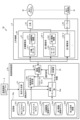
- FIG. 1 is a diagram showing a functional configuration of a machining system according to a first embodiment
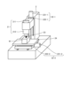
- FIG. A diagram showing an example of the physical configuration of the machine tool shown in FIG. A diagram showing the relationship between the spindle drive system, machine dynamics, and machining process shown in FIG.
- a diagram showing the physical quantities shown in FIG. 3 together with the physical configuration of the machine tool A diagram showing the relationship between the feed drive system, machine dynamics, and machining process shown in FIG.
- FIG. 5 together with the physical configuration of the machine tool
- a diagram for explaining an example of the spindle drive control model of FIG. A diagram for explaining an example of the feed drive control model in FIG.
- FIG. 2 is a diagram for explaining an example of a parameter set generated by the control characteristic setting unit shown in FIG. 1;
- FIG. 2 is a diagram showing a first example of the relationship between the state of the tool and the state of the machined surface of the workpiece during operation of the machine tool shown in FIG. 1;
- FIG. 2 is a diagram showing a second example of the relationship between the state of the tool and the state of the machined surface of the workpiece during operation of the machine tool shown in FIG. 1;
- FIG. 3 is a diagram showing a third example of the relationship between the state of the tool and the state of the machined surface of the workpiece during operation of the machine tool shown in FIG.
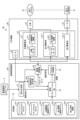
- FIG. 1 Flowchart for explaining the operation of the numerical controller shown in FIG. The figure which shows the function structure of the processing system concerning Embodiment 2.
- FIG. 2 shows dedicated hardware for implementing the functions of the numerical controller, learning device, and reasoning device according to the first to third embodiments;
- FIG. 3 is a diagram showing the configuration of a control circuit for realizing the functions of the numerical controller, learning device, and reasoning device according to the first to third embodiments;
- a numerical control device, a processing system, a numerical control method, and a processing method according to embodiments of the present disclosure will be described in detail below with reference to the drawings.
- a plurality of components having similar functions may be distinguished by adding a hyphen and a number after a common number.
- common numerals are used.
- FIG. 1 is a diagram showing a functional configuration of a machining system 1 according to Embodiment 1.
- a machining system 1 has a machine tool 2 and a numerical controller 3 .
- the numerical control device 3 controls the machine tool 2 by giving the machine tool 2 an operation command generated based on the command described in the numerical control program 4 .
- the machine tool 2 and the numerical controller 3 may be installed in close proximity, or if the numerical controller 3 is connected so as to control the machine tool 2, the numerical controller 3 It may be installed at a location separate from the machine tool 2 .
- the machine tool 2 has one spindle drive system 21, one or more feed drive systems 22, a tool 23 for machining the workpiece W, and a table 24 for holding the workpiece W.
- the spindle drive system 21 has a spindle motor 211 and a spindle drive mechanism 212 driven by the spindle motor 211 .
- a tool 23 is connected to the spindle drive system 21 , and the spindle drive system 21 can rotate the tool 23 .
- the spindle motor 211 or the spindle drive mechanism 212 is provided with an encoder (not shown) that represents angle information of the spindle drive system 21 .
- the feed drive system 22 has a servomotor 221 and a feed drive mechanism 222 driven by the servomotor 221 .
- the feed drive system 22 can change the relative positions of the tool 23 and the workpiece W.
- the servomotor 221 and the feed drive mechanism 222 are provided with encoders (not shown) that represent position information of the feed drive system 22 .
- a table 24 or a tool 23 on which the workpiece W is placed is connected to the feed drive system 22. By moving the table 24 or the tool 23, the feed drive system 22 moves the tool 23 and the workpiece W. can be changed.
- the machine tool 2 has a feed drive system 22-1 for moving the tool 23 and a feed drive system 22-2 for moving the table 24.
- Both the tool 23 and the table 24 are is moved, only the tool 23 may be moved, or only the table 24 may be moved. It is sufficient if the relative position between the tool 23 and the workpiece W held on the table 24 can be changed.
- the feed drive system 22 changes the relative positions of the tool 23 and the workpiece W, so that the tool 23 cuts the workpiece W along the machining path.
- the spindle drive system 21 and the feed drive system 22 are connected to the numerical controller 3, and the spindle motor 211 and the servomotor 221 are controlled by operation commands given from the numerical controller 3.
- the drive system 20 A series of processes in which the cutting edge of the tool 23 penetrates the object W to form a machined surface while generating chips is called a machining process M.
- FIG. 2 is a diagram showing an example of the physical configuration of the machine tool 2 shown in FIG.
- the table 24 has a horizontal surface on which the workpiece W is placed.
- the spindle drive mechanism 212 is provided so that the tool 23 is positioned above the workpiece W held on the table 24 .
- the spindle motor 211 is provided adjacent to the spindle drive mechanism 212 .
- the spindle of a spindle drive system 21 having a spindle motor 211 and a spindle drive mechanism 212 is perpendicular to the horizontal plane of the table 24, and the spindle drive system 21 rotates the tool 23 around the spindle.
- the feed drive mechanism 222-1 of the feed drive system 22-1 that moves the tool 23 is connected to the tool 23 via a structure including the spindle drive mechanism 212 to which the tool 23 is attached.
- the servomotor 221-1 of the feed drive system 22-1 is provided adjacent to the feed drive mechanism 222-1.
- the feed shaft of the feed drive system 22-1 is parallel to the main shaft, and the feed drive system 22-1 moves the tool 23 up and down along the feed shaft.
- a feed drive mechanism 222-2 of a feed drive system 22-2 that moves the table 24 is connected to the table 24.
- the servomotor 221-2 of the feed drive system 22-2 is provided adjacent to the feed drive mechanism 222-2.
- the feed axis of the feed drive system 22-2 is in the horizontal plane of the table 24, and the feed drive system 22-2 moves the table 24 in the horizontal direction.
- the machine tool 2 feeds in a direction perpendicular to the feed shaft of the feed drive system 22-2 and within the horizontal plane of the table 24. It may further have a feed drive system 22 having a shaft.
- the physical configuration shown here is an example for facilitating the explanation, and the physical configuration of the machine tool 2 is not limited to the example shown in FIG.
- the number of feed drive systems 22 of the machine tool 2 may be one, or three or more.
- the directions of the main shaft and the feed shaft are also examples.
- the table 24 is an example of a mechanism for holding the workpiece W, and may be configured so as to be able to hold the workpiece W and control the position relative to the tool 23 .
- the numerical control device 3 has a command generation section 31 , a control characteristic setting section 32 , a storage section 33 , a coupled simulation section 34 , a process evaluation section 35 and a drive control section 36 .
- the numerical control program 4 contains a plurality of commands that instruct the movement of the main shaft and feed shaft of the machine tool 2.
- a command included in the numerical control program 4 is a command for designating a path along which the tool 23 moves by a position relative to the workpiece W, for example.
- the command specifying the path of the tool 23 includes a plurality of position commands specifying positions on the path.
- the numerical control program 4 further includes a spindle rotation speed command indicating the rotation speed of the spindle at the position indicated by each position command, and a feed speed command indicating the movement speed of the feed shaft.
- the numerical control program 4 may be given to the numerical controller 3 from the outside of the numerical controller 3 or may be held internally by the numerical controller 3 .
- the command generation unit 31 analyzes commands written in the numerical control program 4 and generates hourly operation commands given to the machine tool 2 to control the machine tool 2 .
- the command generation unit 31 generates an operation command for causing the machine tool 2 to execute a command written in the numerical control program 4 .
- the command generation unit 31 outputs the generated operation commands to the coupled simulation unit 34 and the drive control unit 36, respectively.
- the control characteristic setting unit 32 generates a set of control characteristic parameters, which are parameters representing the characteristics of controllers provided in the drive control unit 36, which will be described later.
- a set of control characteristic parameters is called a parameter set. Details of the control characteristic parameter will be described later.
- the control characteristic setting unit 32 generates one or more parameter sets and outputs the generated parameter sets to the coupled simulation unit 34 and the drive control unit 36, respectively.
- the storage unit 33 stores a machining process model 331 , a dynamics model 332 , a spindle drive control model 333 , a feed drive control model 334 and machining condition information 335 .
- the storage unit 33 can output the stored information to the coupled simulation unit 34 .
- the machining condition information 335 includes, for example, tool shape information including the number of teeth of the tool 23, the tool diameter and the helix angle, and the depth of cut when the tool 23 is used. Details of the machining process model 331, the dynamics model 332, the spindle drive control model 333, and the feed drive control model 334 will be described later.
- the machining process represents a series of processes in which the cutting edge of the tool 23 penetrates the object W to form a machined surface while generating chips.
- Machine dynamics represents the dynamic behavior of a structure that vibrates due to internal and external vibration sources during machining by the machine tool 2 .
- the structure here can include the tool 23 and the workpiece W in addition to the structure that constitutes the machine tool 2 .
- the drive system 20 is controlled by the numerical controller 3 so that the tool 23 rotates and moves along a predetermined path with respect to the workpiece W.
- the cutting force Fc generated between the tool 23 and the workpiece W is transmitted to the feed drive system 22 as a disturbance force Fd through the structure, and the disturbance torque It is transmitted to the spindle drive system 21 as Td .
- the position of the feed drive system 22 is determined by the amplitude of the disturbance force Fd and Varies according to frequency.
- T d a disturbance torque
- T d when a disturbance torque T d is applied to the spindle drive system 21, the rotation angle of the spindle drive system 21 changes relative to the rotation angle when the tool 23 is not cutting the workpiece W.
- FIG. 3 is a diagram showing the relationship between the spindle drive system 21, machine dynamics, and machining process M shown in FIG.
- FIG. 4 is a diagram showing the physical quantities shown in FIG. 3 together with the physical configuration of the machine tool 2.
- the numerical controller 3 gives an operation command to the spindle drive system 21
- the spindle motor 211 drives the spindle drive mechanism 212
- the structure of the machine tool 2 including the tool 23 rotates, and the workpiece W is machined. do.
- the spindle drive system 21 is controlled to the spindle drive system angle ⁇ 1 based on the operation command, the actual angle of the tool 23 becomes the tool angle ⁇ 2 under the influence of the tool-side mechanical dynamics MD1.
- a series of machining processes M are executed in which the tool 23 enters the workpiece W and forms a machined surface while generating chips.
- the cutting torque Tc generated at this time is fed back to the spindle drive system 21 as a disturbance torque Td through the structure under the influence of the tool-side mechanical dynamics MD1.
- Machine tool 2 outputs a feedback signal to numerical controller 3 . If the state of the spindle drive system 21 receiving the disturbance torque T d is different from the operation command, the numerical controller 3 changes the operation command based on the feedback signal transmitted from the spindle drive system 21 .
- FIG. 5 is a diagram showing the relationship between the feed drive system 22-2, machine dynamics, and machining process M shown in FIG.
- FIG. 6 is a diagram showing the physical quantities shown in FIG. 5 together with the physical configuration of the machine tool 2.
- the numerical controller 3 gives an operation command to the feed drive system 22-2
- the workpiece W is machined by the relative motion between the tool 23 and the workpiece W.
- the servo motor 221-2 of the feed drive system 22-2 drives the feed drive mechanism 222-2 based on the operation command, and as a result, the table 24 undergoes drive system displacement r1.
- the actual displacement generated in the workpiece W becomes the structure displacement r2 under the influence of the workpiece-side mechanical dynamics MD2 when the drive system displacement r1 occurs.
- the cutting force F c generated at this time is fed back to the feed drive system 22-2 as a disturbance force F d through the structure. If the state of the feed drive system 22-2 receiving the disturbance force Fd is different from the operation command, the numerical controller 3 changes the run command based on the feedback signal transmitted from the feed drive system 22-2.
- the spindle drive system 21 and the feed drive system 22 were separately described above for the purpose of explanation.
- the drive system 22 is performed simultaneously.
- the machining process M, the mechanical dynamics, and the drive system 20 form a coupled system, and the numerical controller 3 participates in the machining process M via the drive system 20 and the mechanical dynamics.
- the machining point where the cutting force Fc is generated disappears along with the generation of chips. cannot be detected. Therefore, in order to accurately evaluate the cutting including the motion of the tool 23 and the workpiece W, a simulation including the operation of the spindle drive system 21 and the feed drive system 22 is performed in addition to the machining process M and machine dynamics. There is a need to do.
- machining process model 331 the dynamics model 332, the spindle drive control model 333, and the feed drive control model 334 stored in the storage unit 33 will be described. These models are used when the joint simulation unit 34, which will be described later, performs a simulation.
- the machining process model 331 represents machining characteristics between the tool 23 and the workpiece W.
- FIG. More specifically, the machining process model 331 is a mathematical model that expresses the cutting force Fc generated according to the positional relationship between the tool 23 and the workpiece W.
- Formula (1) shown below is an example of a formula that expresses the cutting force Fc while the cutting edge of the tool 23 is in contact with the workpiece W.
- Formula (1) is calculated using the specific cutting force K c , the edge force coefficient K e , the minute thickness ⁇ a of the cross section of the tool 23, the cut thickness h of the workpiece W, the rotation angle ⁇ of the tool 23, and the time t. It represents the minute cutting force ⁇ F c per cross section of the tool 23 .
- the total cutting force Fc generated by the cutting of the tool 23 can be calculated by summing the minute cutting force ⁇ Fc shown in Equation (1) in the axial direction of the tool 23.
- the cutting thickness h of the workpiece W is the distance between the previously machined surface and the current machined surface in the radial direction of the tool 23 .
- Equation (1) expresses that the cutting force Fc can be calculated from the sum of the force proportional to the cut thickness h and a constant amount of force called edge force.
- the cut thickness h can be expressed by Equation (2) below.
- the cut thickness h is composed of a component representing the nominal cut thickness determined by the feed amount c of the tool 23 per blade, a component representing the relative vibration of the tool 23 and the workpiece W, and a component representing the relative vibration of the tool 23. It is represented by the sum of the component representing the increase or decrease in the cut thickness due to the difference in the radius of rotation of each cutting edge when a plurality of cutting edges are provided.
- the components representing the relative vibration of the tool 23 and the workpiece W are the radial direction component u r of the tool 23 of the relative displacement between the tool 23 and the workpiece W at the moment when the machining surface is cut this time, and the previous machining surface and the tool radial direction component w r of the relative displacement between the tool 23 and the workpiece W transferred to .
- the component representing the increase or decrease in the cut thickness due to the difference in the radius of gyration of each cutting edge is represented by the radius of gyration correction amount ⁇ e of the cutting edge of the tool 23 .
- Formula (1) is an example of the machining process model 331, and the machining process model 331 is not limited to the above.
- a model that calculates the cutting force Fc using voxels expressing the shape of the tool 23 and the shape of the workpiece W may be used.
- the dynamics model 332 represents the dynamic properties of structures that vibrate during operation of the machine tool 2 .
- the dynamics model 332 is a mathematical model representing dynamic displacement of the structure when dynamic force is applied to the structure.
- the behavior of the workpiece W connected to the drive system 20 when the cutting force Fc is applied to the workpiece W can be expressed by the following formula (3).
- Formula (3) is an example of a formula that expresses the vibration of the object W to be processed.
- the cutting force F c generated between the tool 23 and the workpiece W is the relative displacement u between the tool 23 and the workpiece W, the relative displacement v of the drive system 20, and the equivalent mass m of the workpiece W. , the equivalent viscosity coefficient C of the workpiece W, and the equivalent spring constant K of the workpiece W.
- Equation (3) expresses the mechanical dynamics in which the cutting force Fc is transmitted through the workpiece W to the drive system 20 as a disturbance force Fd .
- the dynamics model 332 is not limited to Equation (3).
- it may be a model that expresses the shape of the object W to be processed by voxels and calculates the displacement when the structure vibrates using FEM (Finite Element Method) analysis.
- FEM Finite Element Method
- the dynamics model 332 described here expresses only the vibration of the workpiece W
- the dynamics model 332 expresses the vibration of the tool 23 or other structures instead of the workpiece W. good too.
- the dynamics model 332 may represent vibrations of both the tool 23 and the workpiece W.
- the spindle drive control model 333 represents the spindle drive system 21 of the machine tool 2 and a spindle drive controller that exists in the drive control unit 36 of the numerical controller 3 and is a controller that controls the spindle drive system 21. It is a mathematical model.
- FIG. 7 is a diagram for explaining an example of the spindle drive control model 333 of FIG.
- the spindle drive control model 333 is based on the position control of the spindle drive controller under the condition that the disturbance torque Td caused by the cutting torque Tc is transmitted to the spindle drive system 21 when the spindle rotation angle command is given. It is a mathematical model in which the position and speed of the spindle drive system 21 are controlled by a controller and a speed controller.
- K pp1 , K vp1 , and K vi1 are control gains, which are proportional gain K pp1 for position control, proportional gain K vp1 for velocity control, and integral gain K vi1 for velocity control, respectively.
- P 1 (s) is the torque-to-position transfer function of the entire spindle drive system 21, and s is a complex number. P 1 (s) can be identified from the actual response of the spindle drive system 21 by known system identification techniques.
- the spindle drive system 21 is modeled as a one-inertia system here, the spindle drive system 21 may be modeled as a multi-inertia system.
- a feedforward controller may be added to the spindle drive controller.
- the controller may also have a structure that adds a correction amount for correcting an error factor such as a rotation angle or friction according to the rotation angle.
- the feed drive control model 334 represents the feed drive system 22 of the machine tool 2 and the feed drive controller that exists in the drive control section 36 of the numerical controller 3 and is a controller that controls the feed drive system 22. It is a mathematical model.
- FIG. 8 is a diagram for explaining an example of the feed drive control model 334 of FIG.
- the feed drive control model 334 assumes that the position of the feed drive controller under the condition that the disturbance force Fd caused by the cutting force Fc is transmitted to the feed drive system 22 when the feed drive system position command is given.
- K pp2 , K vp2 , and K vi2 are control gains, which are proportional gain K pp2 for position control, proportional gain K vp2 for velocity control, and integral gain K vi2 for velocity control, respectively.
- P 2 (s) is the force-to-position transfer function of the entire feed drive system 22, where s is a complex number. P 2 (s) can be identified from the actual response of the feed drive system 22 by known system identification techniques.
- the feed drive system 22 is modeled as a one-inertia system here, the feed drive system 22 may be modeled as a multi-inertia system.
- a feedforward controller may be added to the feed drive controller.
- the controller may also have a structure that adds a correction amount for correcting an error factor such as friction according to position or speed.
- This correction amount is, for example, a value obtained by multiplying the position or velocity by a coefficient parameter.
- the controller may also be a structure having a signal processing filter for passing or filtering out certain bands of vibration depending on the frequency parameter.
- a control characteristic parameter is a parameter representing the control characteristic of a controller that controls the drive system 20 . 7 and 8, the control characteristic parameter is the control gain of the controller. Note that the control characteristic parameter is not limited to the control gain, and if the controller has a structure that adds a correction amount for correcting the error factor, the coefficient parameter that determines the correction amount corresponds to the control characteristic parameter. Also, if the controller has a structure having a signal processing filter for passing or excluding vibrations in a specific band, the frequency parameter specifying the band of the signal processing filter corresponds to the control characteristic parameter. Note that the control characteristic parameter is not limited to a constant value, and may be a value that changes with time.
- FIG. 9 is a diagram showing a gain curve representing the response for each frequency when an operation command is input to the drive system 20 shown in FIG.
- FIG. 9 depicts the gain response for three sets of parameters, referred to as the first, second and third sets. Each parameter set has a different gain response, and the peak frequencies of the gain responses of the first, second and third sets are different from each other.
- FIG. 10 is a diagram showing a phase curve representing the response for each frequency when an operation command is input to the driving system 20 shown in FIG. Similar to FIG. 9, FIG. 10 shows phase responses for three different parameter sets, referred to as the first set, the second set and the third set. Each parameter set has a different phase response, and the frequency at which the phase changes in each of the first, second, and third sets of phase responses is different. As shown in FIGS. 9 and 10, the drive system 20 exhibits different frequency characteristics when the control characteristic parameter values are different.
- the control characteristic setting unit 32 generates one or more parameter sets as described above. There are as many controllers as there are spindle drive systems 21 and feed drive systems 22 .
- a parameter set is a set of control characteristic parameters that determine the characteristics of controllers corresponding to the spindle drive system 21 and the feed drive system 22 provided in the machine tool 2 .
- Each parameter set may include one type of control characteristic parameter for one controller, or may include a plurality of types of control characteristic parameter for one controller. For example, if the machine tool 2 has one spindle drive system 21 and two feed drive systems 22, the numerical controller 3 has three controllers.
- one parameter set may include one type and three control characteristic parameter values corresponding to each of the three controllers, or may include a plurality of types of control characteristic parameter values for each controller. It's okay.
- the parameter set is proportional to the position control for the spindle drive controller.
- One gain K pp1 one proportional gain K vp1 for velocity control, and one integral gain K vi1 for velocity control.
- integral gain K vi2 for velocity control.
- FIGS. 7 and 8 show controllers including proportional gains and integral gains, controllers including differential gains may also be used.
- the control characteristic setting unit 32 can set the same value of the control characteristic parameter for each of the plurality of controllers.
- the same value of the control characteristic parameter means that the values of the same type of control characteristic parameter are the same among the plurality of controllers.
- the control characteristic setting unit 32 makes the values of the same type of control characteristic parameter to be set for each of the plurality of controllers the same. be able to.
- the control characteristic setting unit 32 sets proportional gains K pp2 , The values of proportional gain K vp2 and integral gain K vi2 can be the same.
- the plurality of controllers when each of the plurality of controllers operates with the same value of the control characteristic parameter, the plurality of controllers exhibit the same frequency characteristics. Therefore, the system including the drive system 20 and the structure has the same frequency characteristics regardless of the relative feed direction of the tool 23 with respect to the object W to be processed.
- control characteristic setting unit 32 can set control characteristic parameters with different values for each of the plurality of controllers.
- the different values of the control characteristic parameters refer to different values of the same type of control characteristic parameters among the plurality of controllers.
- the control characteristic setting unit 32 can set different values for at least some of the multiple types of control characteristic parameters. In this way, when each of the plurality of controllers operates with control characteristic parameters having different values, the plurality of controllers exhibit different frequency characteristics. Therefore, the system including the drive system 20 and the structure has different frequency characteristics depending on the relative feed direction of the tool 23 with respect to the workpiece W. FIG.
- control characteristic setting unit 32 may set a control characteristic parameter with a different value for each movement direction of the feed drive system 22 corresponding to the controller.
- the machine tool 2 having one spindle drive system 21 and a plurality of feed drive systems 22 corresponding to one spindle drive system 21 has been described.
- the machine tool 2 may also have a plurality of feed drive systems 22 with the same direction of motion.
- the control characteristic setting unit 32 sets control characteristic parameters of the same value for the plurality of feed drive systems 22 with the same motion direction.
- different values of the control characteristic parameters can be set for the plurality of feed drive systems 22 that move in different directions. In this case, the gain response or phase response of the combined system of the structure that vibrates during operation of the machine tool 2 and the feed drive system 22 differs for each movement direction of the feed drive system 22 .
- control characteristic setting unit 32 can change the control characteristic parameter for each of the plurality of controllers over time according to the relative trajectory of the tool 23 with respect to the workpiece W.
- FIG. 11 is a diagram for explaining an example of a parameter set generated by control characteristic setting section 32 shown in FIG. FIG. 11 shows the relative trajectory L drawn by the tool 23 with respect to the workpiece W during operation of the machine tool 2 .
- the feeding direction R1 at each position P on the relative trajectory L and the normal direction R2 of the feeding direction R1 change at each position P. For example, if the relative trajectory L is curved, the normal direction R2-1 at the position P-1 and the position It is different from the normal direction R2-2 at P-2.
- the normal direction R2 represents the normal direction of the relative trajectory L at the position P of the tool 23, and is perpendicular to the feed direction R1 at that position P.
- the control characteristic setting unit 32 changes the control characteristic parameter at each time so that the frequency characteristics are different between the feed direction R1 and the normal direction R2 of the tool 23 .
- the gain response or phase response of the system obtained by synthesizing the structure that causes vibration during operation of the machine tool 2 and the feed drive system 22 is the relative feed direction R1 of the tool 23 with respect to the workpiece W and the law They are different from each other in the line direction R2.
- FIG. 12 is a diagram showing a first example of the relationship between the state of the tool 23 and the state of the machined surface of the workpiece W during operation of the machine tool 2 shown in FIG.
- FIG. 12 shows the first processing surface a1 of the workpiece W and the movement locus b1 of the tool 23 when cutting the first processing surface a1.
- a movement locus b1 represents the vibration of the tool 23 during cutting.
- a thickness v1 of chips obtained by cutting the first machined surface a1 is represented by a difference between the first machined surface a1 and the movement locus b1 of the tool 23 .
- the second processing surface a2 is the surface of the workpiece W after the surface of the first processing surface a1 has been removed by the tool 23, and the tool 23 when cutting the first processing surface a1. becomes a shape corresponding to the movement locus b1 of .
- the vibration of the tool 23 when cutting the first machining surface a1 is transferred to the second machining surface a2. be.
- the thickness v2 of chips when cutting the second machining surface a2 is represented by the difference between the second machining surface a2 and the movement locus b2 of the tool 23 .
- the thickness v2 of chips when cutting the second processing surface a2 depends on the shape of the second processing surface a2 and the vibration of the tool 23 when cutting the second processing surface a2. Varies depending on Therefore, the thickness of the chips of the workpiece W changes due to the vibration of the tool 23 when cutting each surface to be machined.
- the chip thickness v1 when machining the first machining surface a1 and the chip thickness v2 when machining the second machining surface a2 are approximately the same. It has become.
- Such a machining process M is stable and less likely to emanate vibrations.
- FIG. 13 is a diagram showing a second example of the relationship between the state of the tool 23 and the state of the machined surface of the workpiece W during operation of the machine tool 2 shown in FIG.
- FIG. 13 shows the third processing surface a3 of the workpiece W and the movement locus b3 of the tool 23 when cutting the third processing surface a3.
- a thickness v3 of chips when the third machined surface a3 is cut is represented by a difference between the third machined surface a3 and the movement locus b3 of the tool 23 .
- the fourth machined surface a4 is the surface of the workpiece W after the surface of the third machined surface a3 has been removed by the tool 23, and the tool when cutting the third machined surface a3 23 becomes a shape corresponding to the movement locus b3.
- the tool 23 vibrates with a larger amplitude than in the first example while the machine tool 2 is in operation, and the fourth machined surface a4 has an , the vibration of the tool 23 is transferred.
- the thickness v4 of chips when cutting the fourth machined surface a4 is represented by the difference between the fourth machined surface a4 and the movement locus b4 of the tool 23 .
- the amplitude of vibration of the tool 23 is larger in the second example shown in FIG. 13 than in the first example shown in FIG. Therefore, the difference between the chip thickness v3 when machining the third machining surface a3 and the chip thickness v4 when machining the fourth machining surface a4 is the same as the thickness in the first example. It is larger than the difference between the thickness v1 and the thickness v2.
- Such a machining process M is unstable and likely to cause chatter vibration.
- FIG. 14 is a diagram showing a third example of the relationship between the state of the tool 23 and the state of the machined surface of the workpiece W during operation of the machine tool 2 shown in FIG.
- FIG. 14 shows the fifth processing surface a5 of the workpiece W and the movement locus b5 of the tool 23 when cutting the fifth processing surface a5.
- a thickness v5 of chips obtained by cutting the fifth machining surface a5 is represented by a difference between the fifth machining surface a5 and the movement locus b5 of the tool 23 .
- the sixth machined surface a6 is the surface of the workpiece W after the surface of the fifth machined surface a5 is removed by the tool 23, and the tool when cutting the fifth machined surface a5 23 becomes a shape corresponding to the movement locus b5.
- the tool 23 vibrates during operation of the machine tool 2, and the vibration of the tool 23 when cutting the fifth machining surface a5 is transferred to the sixth machining surface a6.
- the thickness v6 of chips when cutting the sixth machined surface a6 is represented by the difference between the sixth machined surface a6 and the movement locus b6 of the tool 23 .
- the difference between the phase of vibration of the tool 23 when cutting the fifth machining surface a5 and the phase of vibration of the tool 23 when cutting the sixth machining surface a6 is the first example.
- the difference between the phase of vibration of the tool 23 when cutting the first machining surface a1 and the phase of vibration of the tool 23 when cutting the second machining surface a2 is larger than The phases are almost reversed. Therefore, the difference between the chip thickness v5 when cutting the fifth machined surface a5 and the chip thickness v6 when cutting the sixth machined surface a6 is the same as in the first example. It is larger than the difference between the thickness v1 and the thickness v2.
- Such a machining process M is unstable as in the second example, and is highly likely to cause chatter vibration.
- the chip thickness changes depending on the vibration state of the tool 23.
- the amplitude and phase of vibration of the tool 23 greatly affect the stability of the machining process M. Therefore, it is possible to stabilize the machining process M by appropriately controlling the amplitude and phase of vibration of the tool 23 .
- the coupled simulation unit 34 gave the operation command output by the command generation unit 31 to the machine tool 2, and controlled the machine tool 2 using a controller having the control characteristics indicated by the parameter set generated by the control characteristics setting unit 32.
- Process information indicating the result of simulating machining in the case is calculated.
- the process information includes parameters with which machining errors can be compared, such as the cut thickness of the workpiece W, the cutting force Fc , the disturbance force Fd, and the like.
- the cut thickness of the workpiece W is the thickness of chips cut by the tool 23 .
- the coupled simulation unit 34 simulates the effects of the operation of the drive system 20 including the spindle drive system 21 and the feed drive system 22 and the dynamics of the structure that causes vibration during operation of the machine tool 2 on the machining process M.
- the coupled simulation unit 34 performs simulations for the number of parameter sets generated by the control characteristic setting unit 32, and generates process information indicating simulation results for the number of parameter sets.
- the coupled simulation unit 34 outputs the generated process information to the process evaluation unit 35 .
- the coupled simulation unit 34 can use the machining process model 331, the dynamics model 332, the spindle drive control model 333, and the feed drive control model 334 to simulate machining performed by the machine tool 2 for each parameter set. Specifically, the coupled simulation unit 34 sets the control characteristic parameter of the spindle drive controller in the spindle drive control model 333 and the control characteristic parameter of the feed drive controller in the feed drive control model 334 to the control characteristic setting unit 32 .
- the coupled simulation unit 34 can use the machining process model 331 , dynamics model 332 , spindle drive control model 333 , feed drive control model 334 and machining condition information 335 stored in the storage unit 33 .
- the designated processing condition becomes the processing condition indicated by the processing condition information 335 .
- the coupled simulation unit 34 simulates the machining process M between the tool 23 and the workpiece W, the mechanical dynamics of the structure of the machine tool 2, the operation of the spindle drive system 21, and the operation of the feed drive system 22. run the generated simulation.
- a coupled model is created by combining each model of a machining process model 331, a dynamics model 332, a spindle drive control model 333, and a feed drive control model 334.
- the control characteristic parameters indicated by the parameter set under the machining conditions described in the machining condition information 335, the drive signal, the spindle drive system angle ⁇ 1, and the drive system displacement r1 when the operation command is given are calculated.
- the tool angle ⁇ 2, the structural displacement r2 of the feed system, the cut thickness h of the workpiece W, the cutting torque Tc , the cutting force Fc, the disturbance torque Td , the disturbance force Fd, and the feedback signal are simulated, and these Co-simulation is performed to calculate the time-series information and frequency component information of .
- the coupled simulation unit 34 performs simulations for the number of parameter sets generated by the control characteristic setting unit 32, and outputs simulation results as process information.
- the process evaluation unit 35 evaluates the magnitude of the machining error when using the parameter set generated by the control characteristic setting unit 32 based on a plurality of pieces of process information output by the coupled simulation unit 34 for each parameter set, A parameter set to be used for controlling the machine tool 2 is selected based on the evaluation result.
- the process evaluation unit 35 outputs a selection signal indicating the selected parameter set to the drive control unit 36 .
- the machining process M coupled with the machine dynamics may be destabilized due to the relationship between the machined surface and the vibration of the tool 23.
- the characteristics of the spindle drive system 21 and the feed drive system 22 change depending on the value of the control characteristic parameter indicated by the parameter set generated by the control characteristic setting unit 32 . Since the tool 23 and the table 24 on which the workpiece W is placed are connected to at least one of the spindle drive system 21 and the feed drive system 22, the mechanical dynamics of the tool 23 and the workpiece W are It can be changed indirectly by a parameter set generated by the control characteristic setting unit 32 .
- the joint simulation unit 34 executes the joint simulation for each parameter set generated by the control characteristic setting unit 32, so that the process evaluation unit 35 evaluates the stability of the machining process M for each parameter set. be able to.
- the process evaluation unit 35 selects the parameter set with which the machining process M is most stable among all the generated parameter sets. This makes it possible to control the machine tool 2 using the parameter set that minimizes the machining error.
- the process evaluation unit 35 can evaluate the magnitude of the machining error based on the change in the cut thickness h of the workpiece W over time.
- the process information generated by the coupled simulation unit 34 includes the cut thickness h of the workpiece W calculated based on the operation command.
- the process evaluation unit 35 evaluates that the smaller the increase in the cut thickness h of the workpiece W, the smaller the machining error.
- the process evaluation unit 35 can select the parameter set that minimizes the increase in the cut thickness h as the parameter set used for controlling the machine tool 2 .
- the cutting thickness h corresponds to the thickness of chips described with reference to FIGS.
- the process evaluation unit 35 can select a parameter set that minimizes the vibration between the tool 23 and the workpiece W by evaluating the change in the cut thickness h over time.
- a parameter set that minimizes vibration between the tool 23 and the workpiece W can stabilize the machining process M and minimize machining errors caused by vibration between the tool 23 and the workpiece W. be able to.
- the process evaluation unit 35 can evaluate the magnitude of the machining error based on the maximum amplitude of the disturbance force Fd or the disturbance torque Td when the operation command is executed for each parameter set. The process evaluation unit 35 evaluates that the smaller the maximum amplitude of the disturbance force Fd or the disturbance torque Td , the smaller the machining error.
- the process evaluation unit 35 can select the parameter set that minimizes the maximum amplitude as the parameter set used for controlling the machine tool 2 .
- the smaller the maximum amplitude of the disturbance force Fd or the disturbance torque Td the smaller the vibration of the drive system 20 caused by the disturbance force Fd or the disturbance torque Td . Therefore, by selecting a parameter set that minimizes the maximum amplitude of the disturbance force Fd or the disturbance torque Td , the machining error caused by the vibration of the drive system 20 can be minimized.
- the process evaluation unit 35 compares the time waveform of the process information calculated by the coupled simulation unit 34 with a preset target profile, and evaluates the magnitude of the machining error based on the deviation from the target profile. can do.
- the target profile is a profile in which the machining error is equal to or less than the allowable value, and is preset inside the process evaluation unit 35, for example.
- the process evaluation unit 35 evaluates that the smaller the deviation from the target profile, the smaller the machining error.
- the process evaluation unit 35 may evaluate the deviation from the target profile based on a loss function such as a square sum error, or may evaluate the deviation from the target profile based on a machine learning technique such as pattern matching. may The process evaluation unit 35 can minimize machining errors by selecting a parameter set that minimizes deviation from the target profile.
- the process evaluation unit 35 may evaluate the magnitude of the machining error using any one of the plurality of evaluation methods described above, or may use a combination of the plurality of evaluation methods described above.
- the drive control unit 36 controls the drive system 20 of the machine tool 2 according to the operation command generated by the command generation unit 31.
- the drive control unit 36 internally includes a spindle drive controller that is a controller for controlling the spindle drive system 21 and a feed drive controller that is a controller for controlling the feed drive system 22 .
- the spindle drive controller outputs a command to the spindle motor 211 so that the position and speed of the spindle drive system 21 become the amounts specified by the operation command while monitoring the signal of the encoder provided in the spindle drive system 21. do.
- the feed drive controller outputs a command to the servo motor 221 while monitoring the signal of the encoder provided in the feed drive system 22 so that the position and speed of the feed drive system 22 are the amounts specified by the operation command. do.
- the drive control unit 36 Based on the selection signal output by the process evaluation unit 35, the drive control unit 36 selects a parameter set to be used for controlling the machine tool 2 from among the parameter sets output by the control characteristic setting unit 32, and controls the spindle drive controller and Let the value of the control characteristic parameter of the feed drive controller be the value of the control characteristic parameter indicated by the selected parameter set.
- FIG. 15 is a flow chart for explaining the operation of the numerical controller 3 shown in FIG.
- the command generator 31 of the numerical control device 3 reads the numerical control program 4, analyzes the read numerical control program 4, and generates an operation command based on the numerical control program 4.
- the control characteristic setting unit 32 generates one or more parameter sets, which are groups of control characteristic parameters (step S101).
- the command generation unit 31 outputs the generated operation command to the coupled simulation unit 34 and the drive control unit 36
- the control characteristic setting unit 32 outputs the generated parameter set to the coupled simulation unit 34 and the drive control unit 36.
- the coupled simulation unit 34 uses the operation command output by the command generation unit 31 and the parameter set output by the control characteristic setting unit 32 to perform a coupled simulation for each parameter set to calculate process information (step S102).
- the coupled simulation unit 34 outputs the calculated process information to the process evaluation unit 35 .
- the process evaluation unit 35 evaluates the process information, evaluates the magnitude of the machining error for each parameter set, and selects the parameter set used for controlling the machine tool 2 (step S103).
- the process evaluation unit 35 outputs a selection signal indicating the selected parameter set to the drive control unit 36 .
- the drive control unit 36 controls the operation of the machine tool 2 using the selected parameter set based on the selection signal output by the process evaluation unit 35 (step S104).
- the command generation unit 31 determines whether reading of all commands described in the numerical control program 4 has been completed (step S105). If the reading has not been completed (step S105: No), the command generator 31 repeats the process from step S101. When the reading is completed (step S105: Yes), the processing system 1 ends the operation.
- the numerical control device 3 provides the machine tool 2 with an operation command generated based on the numerical control program 4.
- Information is calculated for each parameter set including the influence of the operation of the drive system 20 and the dynamics of the structure that causes vibration during the operation of the machine tool 2 on the machining process M of the workpiece W by the tool 23. , selects a parameter set to be used for controlling the machine tool 2 based on the evaluation result of the process information.
- the drive control unit 36 of the numerical controller 3 uses the control characteristic parameters indicated by the selected parameter set to control the machine tool 2 based on the operation command. Therefore, even if the machining process, the operation of the drive system 20, and the mechanical dynamics of the structure that causes vibration during the operation of the machine tool 2 influence each other and machining errors occur, the numerical controller 3 Machining errors can be reduced.
- control characteristic setting unit 32 Since the control characteristic setting unit 32 generates a parameter set that is a set of control characteristic parameters that determine the control characteristic of the drive system 20, the machining efficiency of the machining system 1 does not change.
- the action of the drive system 20 causes the machine in the feed direction R1 of the tool 23 to move. It is possible to realize operation while maintaining the ratio between the dynamics of the dynamics and the dynamics of the mechanical dynamics in the normal direction R2 at each position of the tool 23 .
- the coupled simulation unit 34 includes a machining process model 331 representing machining characteristics between the tool 23 and the workpiece W, a dynamics model 332 representing dynamic characteristics of a structure that causes vibration during operation of the machine tool 2, A spindle drive control model 333 representing the spindle drive system 21 and the spindle drive controller that controls the spindle drive system 21, and a feed drive control model 334 representing the feed drive system 22 and the feed drive controller that controls the feed drive system 22. , and the parameter set generated by the control characteristic setting unit 32 is used to calculate the process information when the operation command is given under the designated machining conditions.
- the storage unit 33 that stores the machining process model 331, the dynamics model 332, the spindle drive control model 333, the feed drive control model 334, and the machining condition information 335 indicating machining conditions is controlled numerically. Although it is provided in the device 3 , the storage unit 33 may be provided outside the numerical control device 3 .
- the storage unit 33 may store different models and machining conditions according to the machining process described in the numerical control program 4.
- the coupled simulation unit 34 can perform simulations using different models and machining conditions depending on the machining process.
- the machine tool 2 has one spindle drive system 21 and one or more feed drive systems 22, but the machine tool 2 has a plurality of spindle drive systems 21. good too. Even if the machine tool 2 has a plurality of spindle drive systems 21, the operation shown in FIG. 15 may be performed in the same manner.
- the machine tool 2 in which the tool 23 is connected to the spindle drive system 21 and the tool 23 rotates for example, like a machining center, was described.
- the workpiece W may be connected to the spindle drive system 21 like a lathe, and the workpiece W may be rotated.
- FIG. 16 is a diagram showing the functional configuration of a processing system 1a according to the second embodiment. Functional configurations having functions similar to those of the first embodiment are denoted by the same reference numerals as those of the first embodiment, and overlapping descriptions are omitted. Differences from the first embodiment will be mainly described below.
- the machining system 1a is different from the machining system 1 in that an operation command is generated based on the simulation result.
- the machining system 1a has a machine tool 2 and a numerical controller 3a.
- the numerical controller 3 a controls the machine tool 2 based on commands written in the numerical control program 4 , similarly to the numerical controller 3 .
- the numerical control device 3a has a command generation section 31, a control characteristic setting section 32a, a storage section 33a, a coupled simulation section 34a, a process evaluation section 35, and a drive control section .
- the storage unit 33a stores a machining process model 331, a dynamics model 332, a spindle drive control model 333, a feed drive control model 334, and machining condition information 335, and stores the stored information. Output to the coupled simulation unit 34a.
- the storage unit 33a can also output the stored information to the control characteristic setting unit 32a.
- the coupled simulation unit 34a calculates process information indicating the result of simulating machining when the machine tool 2 is controlled using the parameter set generated by the control characteristic setting unit 32.
- the coupled simulation unit 34a outputs the calculated process information to the process evaluation unit 35 and also to the control characteristic setting unit 32a.
- the control characteristic setting unit 32a generates one parameter set and outputs it to the coupled simulation unit 34a. Further, the control characteristic setting unit 32a obtains process information generated by the coupled simulation unit 34a using the generated parameter set, and corrects the parameter set based on the obtained process information.
- FIG. 13 A control characteristic parameter is changed so that at least one of gain and phase is changed.
- the control characteristic setting unit 32a increases or decreases the control gain or blocks the band stop filter.
- the stopband is changed so that the band includes the frequency of interest.
- the control characteristic setting unit 32a increases or decreases the control gain or changes the phase compensation amount of the phase compensation filter. By making such a change, it is possible to reduce the phase difference between the phase of vibration transferred to the processing surface to be processed and the phase of vibration of the tool 23 when cutting the processing surface. Based on the process information, the control characteristic setting unit 32a changes the parameter set as in the above example, thereby reducing the variation in the thickness of the chips and adjusting the machining process M as shown in FIG. It is possible to stabilize and reduce machining errors.
- FIG. 17 is a flow chart for explaining the operation of the numerical controller 3a shown in FIG.
- the command generator 31 of the numerical control device 3a reads the numerical control program 4, analyzes the read numerical control program 4, and outputs the commands described in the numerical control program 4 to the machine tool. 2 is generated, and a first parameter set is generated (step S201).
- the command generation unit 31 outputs the generated operation command to the coupled simulation unit 34a and the drive control unit 36, and the control characteristic setting unit 32a transmits the generated first parameter set to the combined simulation unit 34a and the drive control unit 36. output to
- the coupled simulation unit 34a uses the first parameter set generated by the control characteristic setting unit 32a to perform a coupled simulation when the machine tool 2 executes the operation command output by the command generation unit 31 to perform a process. Information is generated (step S202). The coupled simulation unit 34a outputs the generated process information to each of the process evaluation unit 35 and the control characteristic setting unit 32a.
- the control characteristic setting unit 32a corrects the parameter set based on the process information output as a result of executing step S202 to generate a second parameter set (step S203).
- the control characteristic setting unit 32 a outputs the generated second parameter set to the coupled simulation unit 34 a and the drive control unit 36 .
- the coupled simulation unit 34a generates process information by executing a coupled simulation when the machine tool 2 is controlled using the second parameter set output by the control characteristic setting unit 32a (step S204).
- the coupled simulation unit 34a outputs the generated process information to each of the process evaluation unit 35 and the control characteristic setting unit 32a.
- the process evaluation unit 35 compares and evaluates a plurality of pieces of process information, evaluates the magnitude of machining error when each parameter set is used, and selects a parameter set to be used for controlling the machine tool 2 (step S205). .
- the process evaluation unit 35 outputs a selection signal indicating the selected parameter set to the drive control unit 36 .
- the drive control unit 36 controls the operation of the machine tool 2 using the selected parameter set based on the selection signal output by the process evaluation unit 35 (step S206).
- the command generator 31 determines whether or not reading of all commands written in the numerical control program 4 has been completed (step S207). If the reading has not been completed (step S207: No), the command generator 31 repeats the process from step S201. If the reading is completed (step S207: Yes), the processing system 1a ends its operation.
- the control characteristic setting unit 32a corrects the first parameter set based on the process information indicating the simulation results when the machine tool 2 is controlled using the first parameter set, thereby creating the second parameter set.
- a parameter set is generated, and the process evaluation unit 35 selects a parameter set to be used for controlling the machine tool 2 from the first parameter set and the second parameter set.
- the control characteristic setting unit 32a may generate more than two parameter sets.
- the control characteristic setting unit 32a may generate a plurality of parameter sets based on one piece of process information.
- the control characteristic setting unit 32a may repeat modification of the parameter set.
- the control characteristic setting unit 32a may further generate a third parameter set based on process information indicating simulation results when the machine tool 2 is controlled using the second parameter set.
- a machine learning method is used with the amplitude or phase of the vibration component of the cut thickness of the workpiece W as an evaluation value to search for a parameter set that can reduce the vibration of the cut thickness of the workpiece W. method can be adopted.
- FIG. 18 is a diagram showing an example of the configuration of a learning device 50 related to the numerical control device 3a shown in FIG.
- the learning device 50 may be included in the numerical control device 3a shown in FIG. 16, or may be an information processing device different from the numerical control device 3a.
- the learning device 50 has a learning data acquisition unit 51 and a model generation unit 52 .
- the learning data acquisition unit 51 uses the parameter set generated by the control characteristic setting unit 32a and the process information corresponding to the parameter set, that is, the values of the control characteristic parameters indicated by the parameter set to control the machine tool 2.
- Process information indicating the simulation result is acquired as learning data.
- the learning data acquisition unit 51 can output the acquired learning data to the model generation unit 52 .
- the learning data acquisition unit 51 may acquire all of the process information, or may acquire part of the process information.
- the learning data acquisition unit 51 can acquire, as learning data, a parameter indicating the magnitude of the machining error from the process information.
- the learning data acquisition unit 51 can acquire the cutout thickness of the workpiece W, or the amplitude or phase of the vibration component of the cutout thickness of the workpiece W as learning data.
- the model generation unit 52 learns a new parameter set based on the learning data including the parameter set and the process information indicating the simulation results when the machine tool 2 is controlled using the parameter set. That is, the model generator 52 generates a learned model for inferring a new parameter set from the process information of the numerical controller 3a. The model generation unit 52 outputs the generated learned model to the learned model storage unit 53 .
- the learning algorithm used by the model generation unit 52 can be known algorithms such as supervised learning, unsupervised learning, and reinforcement learning. As an example, a case where reinforcement learning is applied will be described.
- reinforcement learning an agent, who is the subject of action in an environment, observes the parameters of the environment that indicate the current state and decides what action to take. The environment dynamically changes according to the actions of the agent, and the agent is rewarded according to the change in the environment. The agent repeats this and learns the course of action that yields the most rewards through a series of actions.
- Q-learning and TD-learning are known. For example, in the case of Q-learning, a general update formula for the action-value function Q(s, a) is represented by Formula (4) below.
- s t represents the state of the environment at time t
- a t represents the action at time t.
- Action a t changes the state to s t+1 .
- r t+1 represents the reward obtained by changing the state
- ⁇ represents the discount rate
- ⁇ represents the learning coefficient.
- ⁇ takes a value in the range of 0 ⁇ 1
- ⁇ takes a value in the range of 0 ⁇ 1.
- the corrective operation command becomes the action at
- the process information becomes the state st
- the learning device 50 learns the best action at in the state at time t.
- the update formula represented by formula (4) increases the action value Q if the action value Q of action a with the highest Q value at time t+1 is greater than the action value Q of action a executed at time t. On the contrary, the action value Q is decreased. In other words, the action value function Q(S, a) is updated so that the action value Q of action a at time t approaches the best action value at time t+1. As a result, the best action value Q in a certain environment is sequentially propagated to the action value Q in the previous environment.
- the model generation unit 52 when generating a trained model by reinforcement learning, includes a reward calculation unit 54 and a function update unit 55.
- the reward calculation unit 54 calculates rewards based on the parameter set and process information.
- the remuneration calculator 54 calculates remuneration r based on remuneration criteria D including remuneration increase criteria D1 and remuneration decrease criteria D2.
- the remuneration standard D is determined based on the size of the processing error indicated by the process information.
- the amplitude of the vibration component of the cut thickness of the workpiece W is used as a parameter indicating the magnitude of the machining error.
- the reward increase criterion D1 is that the amplitude of the vibration component of the cut thickness of the workpiece W is less than the threshold value
- the reward decrease criterion D2 is that the amplitude of the vibration component of the cut thickness of the workpiece W is less than the threshold value. It can be said that it is more than.
- the reward calculation unit 54 increases the reward r by, for example, giving a reward of "+1" when the reward increase criterion D1 is satisfied, and gives a reward of, for example, "-1" when the reward decrease criterion D2 is satisfied. , decrease the reward r.
- the reward calculator 54 outputs the calculated reward r to the function updater 55 .
- the phase of the vibration component of the cut thickness of the workpiece W can be used in addition to the amplitude of the vibration component of the chip thickness.
- the phase of the vibration component of the cutting thickness is the phase of vibration superimposed on the chip shape at the moment when the cutting edge of the tool 23 starts cutting the workpiece W.
- the reward increase criterion D1 is set so that the phase of the vibration component of the cut thickness of the workpiece W is a value within a predetermined range
- the reward decrease criterion D2 is the vibration of the cut thickness of the workpiece W. It is possible that the phase of the component is a value outside the above range.
- the function updating unit 55 updates the function for determining the parameter set according to the reward r calculated by the reward calculating unit 54 and outputs the function to the trained model storage unit 53 .
- the action value function Q(s t , a t ) represented by Equation (4) is used as the function for calculating the corrective driving command.
- the above learning is repeatedly executed.
- the learned model storage unit 53 stores the action value function Q(s t , a t ) updated by the function updating unit 55, that is, the learned model.
- FIG. 19 is a flow chart for explaining the learning process of the learning device 50 shown in FIG.
- the learning data acquisition unit 51 acquires the parameter set generated by the control characteristic setting unit 32a and the process information corresponding to the parameter set as learning data (step S301).
- the model generation unit 52 calculates a reward r based on the parameter set and process information included in the learning data acquired by the learning data acquisition unit 51 (step S302). Specifically, the remuneration calculator 54 acquires the parameter set and process information, and determines whether to increase or decrease the remuneration r based on a predetermined remuneration standard D (step S303). .
- step S303 increase
- step S304 increases the remuneration r
- step S305 decreases the remuneration r
- the function update unit 55 updates the action-value function Q(s t , a t ) stored in the learned model storage unit 53 based on the reward r calculated by the reward calculation unit 54 (step S306).
- the learning device 50 repeatedly executes the processes from step S301 to step S306, and stores the generated action-value function Q(s t , a t ) as a learned model.
- the learned model storage unit 53 is provided outside the learning device 50 in FIG. 18, the learning device 50 may have the learned model storage unit 53 inside.
- the learned model storage section 53 may be provided in the same storage device as the storage section 33a, or may be provided in a separate storage device. .
- FIG. 20 is a diagram showing an example of the configuration of the reasoning device 60 related to the numerical control device 3a shown in FIG.
- the inference device 60 has a data acquisition unit 61 and an inference unit 62 .
- the reasoning device 60 may be provided in the numerical control device 3a, or may be an information processing device different from the numerical control device 3a.
- the inference device 60 is provided, for example, in the command generator 31 of the numerical controller 3a.
- the data acquisition unit 61 acquires process information output by the coupled simulation unit 34a.
- the data acquisition unit 61 outputs the acquired data to the inference unit 62 .
- the inference unit 62 uses the learned model stored in the learned model storage unit 53 to infer a new parameter set from the process information acquired by the data acquisition unit 61 . That is, the inference unit 62 can infer a parameter set suitable for the process information by inputting the process information output by the data acquisition unit 61 to the learned model.
- the inference device 60 outputs a corrective operation command using a learned model obtained by performing machine learning using data acquired from the numerical controller 3a.
- a trained model may be obtained from 3a and a new set of parameters may be output based on this trained model.
- FIG. 21 is a flowchart for explaining the operation of the inference device 60 shown in FIG.
- the data acquisition unit 61 of the inference device 60 acquires process information as data for inference (step S401) and outputs the acquired data to the inference unit 62 .
- the inference unit 62 inputs the process information, which is data for inference acquired in step S401, to the learned model stored in the learned model storage unit 53 (step S402).
- the inference unit 62 outputs a parameter set that is the result of inputting process information to the trained model (step S403).
- the command generation unit 31 of the numerical controller 3a acquires the parameter set output by the inference unit 62 and outputs the acquired parameter set to the coupled simulation unit 34a.
- the inference unit 62 uses reinforcement learning as a learning algorithm, but the learning algorithm used by the inference unit 62 is not limited to reinforcement learning.
- the inference unit 62 can also use supervised learning, unsupervised learning, or semi-supervised learning as learning algorithms other than reinforcement learning.
- model generation unit 52 deep learning that learns to extract the feature amount itself can also be used, and other known methods such as neural networks, genetic programming, function reasoning, etc.
- Machine learning may be performed according to programming, support vector machines, and the like.
- each of the learning device 50 and the reasoning device 60 may be connected to the numerical control device 3a via a network, for example, and may be separate devices from the numerical control device 3a. Further, each of the learning device 50 and the reasoning device 60 may be built in the numerical control device 3a. Furthermore, each of learning device 50 and reasoning device 60 may reside on a cloud server.
- the model generation unit 52 may learn a parameter set using learning data acquired from a plurality of numerical controllers 3a.
- the model generator 52 may acquire learning data from a plurality of numerical controllers 3a used in the same area, or may acquire learning data from a plurality of numerical controllers 3a independently operating in different areas. You may learn a parameter set using the training data which is known. It is also possible to add or exclude the numerical control device 3a that collects the learning data from the targets in the middle.
- the learning device 50 that has learned the parameter set for a certain numerical control device 3a is applied to another numerical control device 3a, and the parameter set is re-learned and updated for the other numerical control device 3a. may
- the numerical control device 3a As described above, the numerical control device 3a according to the second embodiment generates the first parameter set and the second parameter set obtained by modifying the first parameter set using the process information. A parameter set to be used for controlling the machine tool 2 is selected based on the evaluation result of the parameter set.
- the control characteristic setting unit 32a generates a new parameter set based on the results of the simulation performed by the coupled simulation unit 34a. can be done. Therefore, the numerical controller 3a can efficiently reduce machining errors.
- the numerical controller 3a may generate another parameter set from the simulation result of the corrected parameter set. In this case, it is possible to generate a parameter set that can reduce the machining error each time the correction is repeated.
- the learning device 50 can be used to learn the modified parameter set through machine learning.
- Numerical control device 3 a can use the parameter set output by inference device 60 that infers the parameter set using the learned model that is the learning result of learning device 50 .
- the numerical controller 3a can exploratoryly generate parameter sets, so the machining system 1a reduces machining errors without preparing rules for correcting parameter sets in advance. It becomes possible to generate a parameter set that can be
- FIG. 22 is a diagram showing the configuration of a processing system 1b according to the third embodiment. Components having functions similar to those of the first embodiment are denoted by the same reference numerals as those of the first embodiment, and overlapping descriptions are omitted. In the following, parts different from Embodiments 1 and 2 will be mainly described.
- the machining system 1b has a machine tool 2b and a numerical controller 3b.
- the machine tool 2 b has a spindle drive system 21 , a feed drive system 22 , a tool 23 , a table 24 and a sensor 25 .
- the sensor 25 detects vibrations of structures that vibrate during operation of the machine tool 2b.
- the sensor 25 is, for example, an acceleration sensor or force sensor.
- the sensor 25 may be an encoder provided inside the drive system 20 in advance for feedback control of the drive system 20 .
- the sensor 25 is connected to the numerical controller 3b, and a sensor signal obtained by the sensor 25 is output to the numerical controller 3b.
- the numerical control device 3b has a command generation unit 31, a control characteristic setting unit 32b, a storage unit 33, a coupled simulation unit 34, a process evaluation unit 35, and a drive control unit 36.
- the numerical control device 3b differs from the first and second embodiments in that it generates a parameter set based on the sensor signal output from the sensor 25.
- the control characteristic setting unit 32b can generate the first parameter set by the same method as the control characteristic setting unit 32 according to the first embodiment. Further, the control characteristic setting unit 32b can generate a second parameter set, which is a new parameter set, by correcting the first parameter set based on the sensor signal output by the sensor 25.
- the control characteristic setting unit 32b may determine the value of the control characteristic parameter using a machine learning method such as pattern matching when the sensor signal is input.
- the operation of the numerical control device 3b is the same as the operation of the numerical control device 3a shown in FIG. 17 except that the sensor signal is used when modifying the parameter set, so detailed description is omitted here.
- control characteristic setting unit 32b generates the second parameter set by modifying the first parameter set using the sensor signal.
- the control characteristic setting unit 32b may further modify the parameter set using the sensor signal detected when the machine tool 2b is controlled using the parameter set generated using the sensor signal.
- a method of searching for a parameter set that reduces the vibration of the sensor signal can be used using a machine learning method such as reinforcement learning using the amplitude or phase of the vibration component of the sensor signal as an evaluation value.
- a learned model can be obtained using the learning device 50 shown in FIG. 18, and a parameter set can be obtained from the learned model using the inference device 60 shown in FIG.
- the third embodiment can be applied. Description of the method of generating the parameter set used by the numerical controller 3b is omitted.
- the parameter set acquired by the learning data acquisition unit 51 is the parameter set corresponding to the sensor signal, specifically, the parameter set used to control the machine tool 2b when the sensor signal was acquired. .
- the machine tool 2b has the sensor 25, and the control characteristic setting unit 32b of the numerical controller 3b corrects the parameter set based on the sensor signal. can be done. Therefore, the control characteristic setting unit 32b can modify the parameter set according to the state of vibration actually occurring in the machine tool 2b, and can generate a parameter set that efficiently reduces machining errors. can.
- the machining system 1b can generate a parameter set that reduces machining errors without preparing a correction rule for the parameter set in advance. Become.
- the data acquisition unit 51 and the model generation unit 52 for the application, and the data acquisition unit 61 and the inference unit 62 of the inference device 60 are implemented by processing circuits. These processing circuits may be implemented by dedicated hardware, or may be control circuits using a CPU (Central Processing Unit).
- CPU Central Processing Unit
- FIG. 23 is a diagram showing dedicated hardware for realizing the functions of the numerical controllers 3, 3a, 3b, the learning device 50, and the inference device 60 according to the first to third embodiments.
- the processing circuit 90 is a single circuit, a composite circuit, a programmed processor, a parallel programmed processor, an ASIC (Application Specific Integrated Circuit), an FPGA (Field Programmable Gate Array), or a combination thereof.
- this control circuit is, for example, the control circuit 91 having the configuration shown in FIG.
- FIG. 24 is a diagram showing the configuration of a control circuit 91 for implementing the functions of the numerical controllers 3, 3a, 3b, learning device 50, and reasoning device 60 according to the first to third embodiments.
- the control circuit 91 has a processor 92 and a memory 93 .
- the processor 92 is a CPU, and is also called an arithmetic unit, microprocessor, microcomputer, DSP (Digital Signal Processor), or the like.
- the memory 93 is, for example, non-volatile or volatile semiconductor memory such as RAM (Random Access Memory), ROM (Read Only Memory), flash memory, EPROM (Erasable Programmable ROM), EEPROM (registered trademark) (Electrically EPROM), They include magnetic discs, flexible discs, optical discs, compact discs, mini discs, and DVDs (Digital Versatile Disks).
- the control circuit 91 When the above processing circuit is implemented by the control circuit 91, it is implemented by the processor 92 reading and executing a program stored in the memory 93 and corresponding to the processing of each component.
- the memory 93 is also used as temporary memory in each process executed by the processor 92 .
- the program executed by the processor 92 may be stored in a storage medium and provided, or may be provided via a communication channel. Further, the functions of the numerical controllers 3, 3a, 3b, the learning device 50, and the reasoning device 60 according to the first to third embodiments are either the processing circuit 90 shown in FIG. 23 or the control circuit 91 shown in FIG. Either one may be used, or the processing circuit 90 and the control circuit 91 may be used in combination.
Landscapes
- Engineering & Computer Science (AREA)
- Human Computer Interaction (AREA)
- Manufacturing & Machinery (AREA)
- Physics & Mathematics (AREA)
- General Physics & Mathematics (AREA)
- Automation & Control Theory (AREA)
- Mechanical Engineering (AREA)
- Numerical Control (AREA)
Priority Applications (4)
| Application Number | Priority Date | Filing Date | Title |
|---|---|---|---|
| JP2022517516A JP7166488B1 (ja) | 2021-09-30 | 2021-09-30 | 数値制御装置、加工システム、数値制御方法および加工方法 |
| CN202180102587.5A CN118019614A (zh) | 2021-09-30 | 2021-09-30 | 数控装置、加工系统、数控方法及加工方法 |
| PCT/JP2021/036266 WO2023053400A1 (ja) | 2021-09-30 | 2021-09-30 | 数値制御装置、加工システム、数値制御方法および加工方法 |
| DE112021008302.3T DE112021008302T5 (de) | 2021-09-30 | 2021-09-30 | Numerische steuervorrichtung, bearbeitungssystem, numerisches steuerverfahren und bearbeitungsverfahren |
Applications Claiming Priority (1)
| Application Number | Priority Date | Filing Date | Title |
|---|---|---|---|
| PCT/JP2021/036266 WO2023053400A1 (ja) | 2021-09-30 | 2021-09-30 | 数値制御装置、加工システム、数値制御方法および加工方法 |
Publications (1)
| Publication Number | Publication Date |
|---|---|
| WO2023053400A1 true WO2023053400A1 (ja) | 2023-04-06 |
Family
ID=83931100
Family Applications (1)
| Application Number | Title | Priority Date | Filing Date |
|---|---|---|---|
| PCT/JP2021/036266 Ceased WO2023053400A1 (ja) | 2021-09-30 | 2021-09-30 | 数値制御装置、加工システム、数値制御方法および加工方法 |
Country Status (4)
| Country | Link |
|---|---|
| JP (1) | JP7166488B1 (https=) |
| CN (1) | CN118019614A (https=) |
| DE (1) | DE112021008302T5 (https=) |
| WO (1) | WO2023053400A1 (https=) |
Cited By (2)
| Publication number | Priority date | Publication date | Assignee | Title |
|---|---|---|---|---|
| CN117148783A (zh) * | 2023-10-30 | 2023-12-01 | 南通百盛精密机械有限责任公司 | 数控机床的刀具参数自动化校正方法 |
| JP7741265B1 (ja) * | 2024-09-03 | 2025-09-17 | 株式会社牧野フライス製作所 | 工作機械、加工方法 |
Families Citing this family (1)
| Publication number | Priority date | Publication date | Assignee | Title |
|---|---|---|---|---|
| JP7224541B1 (ja) * | 2021-09-30 | 2023-02-17 | 三菱電機株式会社 | 数値制御装置、加工システム、数値制御方法および加工方法 |
Citations (7)
| Publication number | Priority date | Publication date | Assignee | Title |
|---|---|---|---|---|
| JPH0395605A (ja) * | 1989-09-08 | 1991-04-22 | Toshiba Mach Co Ltd | Ncサーボシミュレータ |
| JP2002287816A (ja) * | 2001-03-27 | 2002-10-04 | Yaskawa Electric Corp | 遠隔調整及び診断装置 |
| JP2004188541A (ja) * | 2002-12-11 | 2004-07-08 | Yamazaki Mazak Corp | 工作機械の送り軸パラメータ調整システム |
| JP2009122779A (ja) * | 2007-11-12 | 2009-06-04 | Mitsubishi Electric Corp | 制御システムおよび制御支援装置 |
| JP2016093882A (ja) * | 2014-11-07 | 2016-05-26 | 株式会社ジェイテクト | 歯車加工装置及び歯車加工方法 |
| JP2019021235A (ja) * | 2017-07-21 | 2019-02-07 | ファナック株式会社 | 機械学習装置、数値制御装置、数値制御システム、及び機械学習方法 |
| WO2019043852A1 (ja) * | 2017-08-30 | 2019-03-07 | 三菱電機株式会社 | 数値制御システムおよびモータ制御装置 |
Family Cites Families (8)
| Publication number | Priority date | Publication date | Assignee | Title |
|---|---|---|---|---|
| JPS61120213A (ja) * | 1984-11-16 | 1986-06-07 | Canon Inc | 位置決め制御装置 |
| JP2745850B2 (ja) * | 1991-03-29 | 1998-04-28 | 三菱電機株式会社 | 数値制御装置、数値制御システム、制御パラメータの自動調整方法、特徴量判定基準変更方法および複数の調整条件総合判定方法 |
| JP3399419B2 (ja) * | 1999-10-28 | 2003-04-21 | 三菱電機株式会社 | 数値制御シミュレーション装置 |
| JP4223894B2 (ja) * | 2003-08-21 | 2009-02-12 | 株式会社山武 | Pidパラメータ調整装置 |
| JP5942423B2 (ja) | 2011-12-27 | 2016-06-29 | 株式会社ジェイテクト | 加工面性状算出装置、加工面性状算出方法、加工条件決定装置および加工条件決定方法 |
| DE102014013169A1 (de) * | 2014-09-04 | 2016-03-10 | Bernd Seidel | Verfahren und Vorrichtung zum Ermitteln optimaler Einsatzparameter von Schaufelradbaggern und Schneidwalzen. |
| US9623502B2 (en) * | 2014-11-07 | 2017-04-18 | Jtekt Corporation | Gear machining device and gear machining method |
| JP7224541B1 (ja) * | 2021-09-30 | 2023-02-17 | 三菱電機株式会社 | 数値制御装置、加工システム、数値制御方法および加工方法 |
-
2021
- 2021-09-30 JP JP2022517516A patent/JP7166488B1/ja active Active
- 2021-09-30 DE DE112021008302.3T patent/DE112021008302T5/de not_active Withdrawn
- 2021-09-30 CN CN202180102587.5A patent/CN118019614A/zh active Pending
- 2021-09-30 WO PCT/JP2021/036266 patent/WO2023053400A1/ja not_active Ceased
Patent Citations (7)
| Publication number | Priority date | Publication date | Assignee | Title |
|---|---|---|---|---|
| JPH0395605A (ja) * | 1989-09-08 | 1991-04-22 | Toshiba Mach Co Ltd | Ncサーボシミュレータ |
| JP2002287816A (ja) * | 2001-03-27 | 2002-10-04 | Yaskawa Electric Corp | 遠隔調整及び診断装置 |
| JP2004188541A (ja) * | 2002-12-11 | 2004-07-08 | Yamazaki Mazak Corp | 工作機械の送り軸パラメータ調整システム |
| JP2009122779A (ja) * | 2007-11-12 | 2009-06-04 | Mitsubishi Electric Corp | 制御システムおよび制御支援装置 |
| JP2016093882A (ja) * | 2014-11-07 | 2016-05-26 | 株式会社ジェイテクト | 歯車加工装置及び歯車加工方法 |
| JP2019021235A (ja) * | 2017-07-21 | 2019-02-07 | ファナック株式会社 | 機械学習装置、数値制御装置、数値制御システム、及び機械学習方法 |
| WO2019043852A1 (ja) * | 2017-08-30 | 2019-03-07 | 三菱電機株式会社 | 数値制御システムおよびモータ制御装置 |
Cited By (4)
| Publication number | Priority date | Publication date | Assignee | Title |
|---|---|---|---|---|
| CN117148783A (zh) * | 2023-10-30 | 2023-12-01 | 南通百盛精密机械有限责任公司 | 数控机床的刀具参数自动化校正方法 |
| CN117148783B (zh) * | 2023-10-30 | 2023-12-26 | 南通百盛精密机械有限责任公司 | 数控机床的刀具参数自动化校正方法 |
| JP7741265B1 (ja) * | 2024-09-03 | 2025-09-17 | 株式会社牧野フライス製作所 | 工作機械、加工方法 |
| WO2026053781A1 (ja) * | 2024-09-03 | 2026-03-12 | 株式会社牧野フライス製作所 | 工作機械、加工方法 |
Also Published As
| Publication number | Publication date |
|---|---|
| JP7166488B1 (ja) | 2022-11-07 |
| CN118019614A (zh) | 2024-05-10 |
| JPWO2023053400A1 (https=) | 2023-04-06 |
| DE112021008302T5 (de) | 2024-08-01 |
Similar Documents
| Publication | Publication Date | Title |
|---|---|---|
| JP7166488B1 (ja) | 数値制御装置、加工システム、数値制御方法および加工方法 | |
| US10921774B2 (en) | Machine learning devices and methods for optimizing the speed and accuracy of thread mill, inner diameter, outer shape, and surface machine tools | |
| US11179851B2 (en) | Robot control device, robot control parameter adjustment method, and non-transitory storage medium storing program | |
| US10261497B2 (en) | Machine tool for generating optimum acceleration/deceleration | |
| JP7010877B2 (ja) | 機械学習装置、数値制御システム及び機械学習方法 | |
| US10331104B2 (en) | Machine tool, simulation apparatus, and machine learning device | |
| WO2019239553A1 (ja) | 機械学習装置、補正パラメータ調整装置および機械学習方法 | |
| JP6978452B2 (ja) | 機械学習装置、制御装置、及び機械学習の探索範囲の設定方法 | |
| CN109274314A (zh) | 机器学习装置、伺服电动机控制装置、伺服电动机控制系统以及机器学习方法 | |
| JP6748135B2 (ja) | 機械学習装置、サーボ制御装置、サーボ制御システム、及び機械学習方法 | |
| CN111722530B (zh) | 机器学习装置、控制系统以及机器学习方法 | |
| JP6577508B2 (ja) | 制御装置 | |
| US20170090452A1 (en) | Machine tool for generating speed distribution | |
| JP6841801B2 (ja) | 機械学習装置、制御システム及び機械学習方法 | |
| JP7313585B1 (ja) | 駆動条件決定装置および駆動条件決定方法 | |
| JP7224541B1 (ja) | 数値制御装置、加工システム、数値制御方法および加工方法 | |
| WO2025004241A1 (ja) | パラメータ調整装置およびパラメータ調整方法 | |
| WO2022030346A1 (ja) | 制御支援装置、制御システム及び制御支援方法 | |
| JP7175403B2 (ja) | 加工プログラム変換装置、数値制御装置および加工プログラムの変換方法 | |
| JP4918682B2 (ja) | 超音波モータの制御方法、超音波モータ制御装置及び超音波モータを制御するためのプログラム | |
| JP2006277652A (ja) | サーボゲイン算出方法、サーボゲイン算出プログラム及びサーボゲイン算出装置 | |
| JP7741190B2 (ja) | 安定余裕の設定支援装置、制御システム及び設定支援方法 | |
| DiMarco | Robust interpolation and iterative learning strategies for modulated tool path planning |
Legal Events
| Date | Code | Title | Description |
|---|---|---|---|
| WWE | Wipo information: entry into national phase |
Ref document number: 2022517516 Country of ref document: JP |
|
| 121 | Ep: the epo has been informed by wipo that ep was designated in this application |
Ref document number: 21959435 Country of ref document: EP Kind code of ref document: A1 |
|
| WWE | Wipo information: entry into national phase |
Ref document number: 202180102587.5 Country of ref document: CN |
|
| WWE | Wipo information: entry into national phase |
Ref document number: 112021008302 Country of ref document: DE |
|
| 122 | Ep: pct application non-entry in european phase |
Ref document number: 21959435 Country of ref document: EP Kind code of ref document: A1 |