WO2023053353A1 - 鞍乗型車両 - Google Patents
鞍乗型車両 Download PDFInfo
- Publication number
- WO2023053353A1 WO2023053353A1 PCT/JP2021/036163 JP2021036163W WO2023053353A1 WO 2023053353 A1 WO2023053353 A1 WO 2023053353A1 JP 2021036163 W JP2021036163 W JP 2021036163W WO 2023053353 A1 WO2023053353 A1 WO 2023053353A1
- Authority
- WO
- WIPO (PCT)
- Prior art keywords
- engine
- straddle
- type vehicle
- state
- notification
- Prior art date
- Legal status (The legal status is an assumption and is not a legal conclusion. Google has not performed a legal analysis and makes no representation as to the accuracy of the status listed.)
- Ceased
Links
Images





Classifications
-
- F—MECHANICAL ENGINEERING; LIGHTING; HEATING; WEAPONS; BLASTING
- F02—COMBUSTION ENGINES; HOT-GAS OR COMBUSTION-PRODUCT ENGINE PLANTS
- F02D—CONTROLLING COMBUSTION ENGINES
- F02D29/00—Controlling engines, such controlling being peculiar to the devices driven thereby, the devices being other than parts or accessories essential to engine operation, e.g. controlling of engines by signals external thereto
- F02D29/02—Controlling engines, such controlling being peculiar to the devices driven thereby, the devices being other than parts or accessories essential to engine operation, e.g. controlling of engines by signals external thereto peculiar to engines driving vehicles; peculiar to engines driving variable pitch propellers
-
- B—PERFORMING OPERATIONS; TRANSPORTING
- B62—LAND VEHICLES FOR TRAVELLING OTHERWISE THAN ON RAILS
- B62J—CYCLE SADDLES OR SEATS; AUXILIARY DEVICES OR ACCESSORIES SPECIALLY ADAPTED TO CYCLES AND NOT OTHERWISE PROVIDED FOR, e.g. ARTICLE CARRIERS OR CYCLE PROTECTORS
- B62J43/00—Arrangements of batteries
- B62J43/30—Arrangements of batteries for providing power to equipment other than for propulsion
-
- B—PERFORMING OPERATIONS; TRANSPORTING
- B62—LAND VEHICLES FOR TRAVELLING OTHERWISE THAN ON RAILS
- B62J—CYCLE SADDLES OR SEATS; AUXILIARY DEVICES OR ACCESSORIES SPECIALLY ADAPTED TO CYCLES AND NOT OTHERWISE PROVIDED FOR, e.g. ARTICLE CARRIERS OR CYCLE PROTECTORS
- B62J50/00—Arrangements specially adapted for use on cycles not provided for in main groups B62J1/00 - B62J45/00
- B62J50/20—Information-providing devices
- B62J50/21—Information-providing devices intended to provide information to rider or passenger
- B62J50/22—Information-providing devices intended to provide information to rider or passenger electronic, e.g. displays
-
- B—PERFORMING OPERATIONS; TRANSPORTING
- B62—LAND VEHICLES FOR TRAVELLING OTHERWISE THAN ON RAILS
- B62M—RIDER PROPULSION OF WHEELED VEHICLES OR SLEDGES; POWERED PROPULSION OF SLEDGES OR SINGLE-TRACK CYCLES; TRANSMISSIONS SPECIALLY ADAPTED FOR SUCH VEHICLES
- B62M7/00—Motorcycles characterised by position of motor or engine
- B62M7/02—Motorcycles characterised by position of motor or engine with engine between front and rear wheels
-
- F—MECHANICAL ENGINEERING; LIGHTING; HEATING; WEAPONS; BLASTING
- F02—COMBUSTION ENGINES; HOT-GAS OR COMBUSTION-PRODUCT ENGINE PLANTS
- F02N—STARTING OF COMBUSTION ENGINES; STARTING AIDS FOR SUCH ENGINES, NOT OTHERWISE PROVIDED FOR
- F02N11/00—Starting of engines by means of electric motors
- F02N11/08—Circuits specially adapted for starting of engines
- F02N11/0814—Circuits specially adapted for starting of engines comprising means for controlling automatic idle-start-stop
- F02N11/0818—Conditions for starting or stopping the engine or for deactivating the idle-start-stop mode
- F02N11/0825—Conditions for starting or stopping the engine or for deactivating the idle-start-stop mode related to prevention of engine restart failure, e.g. disabling automatic stop at low battery state
-
- H—ELECTRICITY
- H02—GENERATION; CONVERSION OR DISTRIBUTION OF ELECTRIC POWER
- H02J—ELECTRIC POWER NETWORKS; CIRCUIT ARRANGEMENTS OR SYSTEMS FOR SUPPLYING OR DISTRIBUTING ELECTRIC POWER; SYSTEMS FOR STORING ELECTRIC ENERGY
- H02J9/00—Circuit arrangements for emergency or stand-by power supply, e.g. for emergency lighting
- H02J9/002—Circuit arrangements for emergency or stand-by power supply, e.g. for emergency lighting in which a reserve is maintained in an energy source by disconnecting non-critical loads, e.g. maintaining a reserve of charge in a vehicle battery for starting an engine
-
- H—ELECTRICITY
- H02—GENERATION; CONVERSION OR DISTRIBUTION OF ELECTRIC POWER
- H02J—ELECTRIC POWER NETWORKS; CIRCUIT ARRANGEMENTS OR SYSTEMS FOR SUPPLYING OR DISTRIBUTING ELECTRIC POWER; SYSTEMS FOR STORING ELECTRIC ENERGY
- H02J2105/00—Networks for supplying or distributing electric power characterised by their spatial reach or by the load
- H02J2105/30—Networks for supplying or distributing electric power characterised by their spatial reach or by the load the load networks being external to vehicles, i.e. exchanging power with vehicles
-
- H—ELECTRICITY
- H02—GENERATION; CONVERSION OR DISTRIBUTION OF ELECTRIC POWER
- H02J—ELECTRIC POWER NETWORKS; CIRCUIT ARRANGEMENTS OR SYSTEMS FOR SUPPLYING OR DISTRIBUTING ELECTRIC POWER; SYSTEMS FOR STORING ELECTRIC ENERGY
- H02J2105/00—Networks for supplying or distributing electric power characterised by their spatial reach or by the load
- H02J2105/50—Networks for supplying or distributing electric power characterised by their spatial reach or by the load for selectively controlling the operation of the loads
- H02J2105/51—Networks for supplying or distributing electric power characterised by their spatial reach or by the load for selectively controlling the operation of the loads according to a condition being electrical
-
- H—ELECTRICITY
- H02—GENERATION; CONVERSION OR DISTRIBUTION OF ELECTRIC POWER
- H02J—ELECTRIC POWER NETWORKS; CIRCUIT ARRANGEMENTS OR SYSTEMS FOR SUPPLYING OR DISTRIBUTING ELECTRIC POWER; SYSTEMS FOR STORING ELECTRIC ENERGY
- H02J7/00—Circuit arrangements for charging or discharging batteries or for supplying loads from batteries
- H02J7/80—Circuit arrangements for charging or discharging batteries or for supplying loads from batteries including monitoring or indicating arrangements
Definitions
- the present invention relates to a straddle-type vehicle.
- idle stop control In straddle-type vehicles, idle stop control is known that automatically stops the engine of the vehicle when a predetermined condition is met, and restarts the engine when a start operation is detected while the engine is automatically stopped.
- power supply to various electrical loads continues, so the battery voltage drops. Therefore, when stopping the engine, it is necessary to secure the battery voltage for restarting the engine.
- Patent Document 1 in order to prevent the engine from being unable to restart due to the drop in battery voltage in a continuously variable transmission vehicle, the state of charge of the battery is detected and a warning is issued under predetermined conditions. , to restart the engine.
- the present invention provides a technology that makes it easier to secure the battery voltage necessary for restarting the engine while suppressing vehicle operations unintended by the rider in a vehicle that performs idle stop control.
- engine and a manual transmission that shifts the rotation of the engine and transmits it to the driving wheels; idle stop control means for performing idle stop control for automatically stopping the engine when an idle stop condition is satisfied;
- a straddle-type vehicle comprising a battery that stores electric power necessary for starting the engine, notification means for notifying a rider to restart the engine when the battery voltage of the battery becomes equal to or lower than a first threshold value while the engine is automatically stopped while the transmission is in the in-gear state; , After the notification, the power supply state of the straddle-type vehicle is changed to a first state with lower power consumption than when the notification was made, at least on condition that the restart operation of the engine has not been confirmed.
- FIG. 1 is a left side view of a straddle-type vehicle according to one embodiment
- FIG. FIG. 2 is a top view of the straddle-type vehicle of FIG. 1
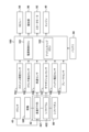
- FIG. 2 is a diagram showing an example of the hardware configuration of the straddle-type vehicle shown in FIG.
- 4 is a flowchart showing an example of processing performed by an idle stop ECU; 4 is a flowchart showing an example of processing performed by an idle stop ECU; 4 is a flowchart showing an example of processing performed by an idle stop ECU; 4 is a flowchart showing an example of processing performed by a power supply control ECU; 4 is a flowchart showing an example of processing performed by an idle stop ECU;
- FIG. 1 is a left side view of a straddle-type vehicle 10
- FIG. 2 is a top view of the straddle-type vehicle 10.
- FIG. 1 the directions of front and back, up and down, and left and right will be explained according to the directions of the arrows shown in FIGS. 1 and 2 unless otherwise specified.
- the straddle-type vehicle 10 has a double-cradle-type vehicle body frame 12 .
- This body frame 12 has a head pipe 14 , a pair of left and right main frames 16 , and a down frame 18 .
- the pair of left and right main frames 16 branch left and right from the head pipe 14 and extend rearward in a gently descending rearward direction, and then extend downward via a curved portion 16a.
- the down frame 18 branches left and right from the head pipe 14 and extends obliquely rearward and downward under the main frame 16 , and then extends substantially horizontally rearward via a curved portion 18 a to reach the rear end portion of the main frame 16 . Connected.
- the body frame 12 further includes a pair of left and right seat frames 20, a pair of left and right pivot plates 22, and a pair of left and right reinforcing stays 24.
- the pair of left and right seat frames 20 extend rearward and slightly upward from the vicinity of the curved portion 16a of the pair of left and right main frames 16 .
- a pair of left and right pivot plates 22 are arranged near the rear end of the main frame 16 .
- a pair of left and right reinforcing stays 24 are connected to the seat frame 20 by extending obliquely rearward from the vicinity of the pivot plate 22 of the main frame 16 .
- a pivot 26 is provided on the pair of left and right pivot plates 22 .
- a pair of left and right front forks 28 are rotatably supported by the head pipe 14, and a handlebar 32 for steering is attached to the upper ends of the pair of left and right front forks 28 via a top bridge 30a.
- a meter section 34 having a speedometer and the like is attached to the top bridge 30a.
- a headlight 36 for illuminating the front of the straddle-type vehicle 10 and a pair of left and right front winkers 37 are provided in front of the head pipe 14 and the bottom bridge 30b.
- the front wheel WF is rotatably supported by a pair of left and right front forks 28, and a front fender 38 is provided above the front wheel WF.
- An engine 40 and a manual transmission 42 are provided between the main frame 16 and the down frame 18 , and a fuel tank 44 is attached above the engine 40 and above the front side of the main frame 16 .
- An exhaust pipe 46 is attached to the engine 40 and a muffler 48 is connected to the exhaust pipe 46 .
- the oil cooler 50 is provided in front of the engine 40 and on the front side of the down frame 18 , and the throttle body 52 and the air cleaner 54 are provided behind the engine 40 .
- a swing arm 56 is pivotally supported by the pair of left and right pivot plates 22 via a pivot 26 so as to be capable of swinging in a substantially vertical direction. 58 is interposed.
- a rear wheel WR which is a drive wheel, is rotatably supported at the rear end of the swing arm 56 .
- the power of engine 40 is transmitted to rear wheels WR via chain 60 .
- a pair of left and right step holders 62 are fixed to the pair of left and right pivot plates 22 and extend rearwardly. are installed on the left and right.
- a seat 68 for the driver and fellow passengers to sit on (straddle) is attached behind the fuel tank 44 and above the seat frame 20.
- the seat 68 serves as a driver's seat 68a on which the driver rides.
- a passenger seat 68b on which a fellow passenger rides.
- a grab bar 70 held by a fellow passenger and a rear blinker 72 are attached to the rear portion of the seat frame 20 .
- a rear fender 74 is provided behind the seat frame 20 , and a tail lamp 76 is attached to the rear fender 74 .
- the right end of the handlebar 32 is provided with a throttle grip 80 that instructs the handlebar 32 to rotate and accelerate.
- the handlebar 32 is provided with a brake lever (brake operator) 82 for braking the front wheels of the straddle-type vehicle 10 for applying a braking force to the front wheels.
- a brake lever brake operator
- a braking device not shown provided on the front wheels WF is actuated to apply a braking force to the front wheels WF.
- a foot brake pedal (brake operator) 84 for braking the rear wheels for applying braking force to the rear wheels of the straddle-type vehicle 10 is provided in front of the step 64 on the right side.
- a brake device (not shown) provided for the rear wheel WR operates to apply braking force to the rear wheel WR.
- the handlebar 32 is provided with a clutch lever 86 in front of the left end of the handlebar 32 .
- This clutch lever 86 is for operating a clutch 43 (see FIG. 3) that cuts off transmission of the driving force of the engine 40 to the manual transmission 42 .
- a shift pedal 88 is provided in front of the left step 64 for selectively shifting gears having different transmission ratios of the manual transmission 42 . When the driver places his or her left foot on the left step 64 and operates the gear change pedal 88 with his or her left foot, the transmission gear of the manual transmission 42 is switched.
- FIG. 3 is a block diagram showing an example of the hardware configuration of the straddle-type vehicle 10. As shown in FIG. FIG. 3 mainly shows constituent elements necessary for an example of idle stop control processing, which will be described later.
- the control unit 100 includes a power control ECU (Electronic Control Unit) 101 and an idle stop ECU 102 .
- Each ECU includes a processor represented by a CPU, a storage device such as a semiconductor memory, an interface with an external device, and the like.
- the storage device stores programs executed by the processor, data used for processing by the processor, and the like.
- Each ECU may include a plurality of processors, storage devices, interfaces, and the like. Further, each ECU can be connected to each other via a network (not shown) such as a CAN (Controller Area Network) to exchange data.
- FIG. 3 shows an ECU related to a processing example to be described later. However, the number of ECUs included in the control unit 100 and the functions that each ECU takes charge of can be designed appropriately, and it is possible to subdivide or integrate them more than in the present embodiment.
- the power control ECU 101 controls the power state of the straddle-type vehicle 10 .
- the power supply state can be changed by the rider's operation such as key operation or button depression. Power state can be controlled.
- the power state of the straddle-type vehicle 10 includes a power-off state in which both the ignition power source and the accessory power source are off, an accessory-on state in which only the accessory power source is on, and a power-on state in which both of these power sources are on. Transition between states.
- the mode of the power supply state of the straddle-type vehicle 10 is not limited to this.
- the power state of the straddle-type vehicle 10 may include a state in which only the ignition power source is on, a state in which a plurality of systems of ignition power sources or accessory power sources are provided, and at least some of them are on.
- the power control ECU 101 controls the power state of the straddle-type vehicle 10 by, for example, switching on and off an IG (ignition) relay 94 or an ACC (accessory) relay (not shown).
- the idle stop ECU 102 executes idle stop control. Although the details will be described later, the idle stop ECU 102 automatically stops the engine 40 when a predetermined idle stop condition is satisfied. Further, the idling stop ECU 102 restarts the automatically stopped engine 40 by the starter motor 92 when a predetermined idling stop end condition is satisfied.
- the battery 90 stores and supplies electric power necessary for operating various electrical components of the straddle-type vehicle 10 .
- the battery 90 supplies electric power to electric components of a running system necessary for running.
- the electrical components of the running system include, for example, each ECU, various electrical components such as the starter motor 92 and spark plugs used for starting or driving the engine 40, lighting devices such as the headlights 36, various instruments for notifying the rider of the vehicle state, and the like.
- the battery 90 also supplies electric power to non-running electrical components that are used for purposes other than running.
- the non-driving electrical equipment may include, for example, an audio system, a grip heater that warms the grip, an electric windshield that can electrically adjust the shield angle (none of which are shown), and the like.
- the straddle-type vehicle 10 may include various sensors that detect the state of the vehicle itself or the surrounding environment.
- the straddle-type vehicle 10 includes a throttle opening sensor 104 , a clutch detection sensor 105 , a vehicle speed sensor 106 , a gear position sensor 107 , a battery voltage sensor 108 and a brake sensor 109 .
- a throttle opening sensor 104 detects the throttle opening due to the rider's throttle operation.
- a clutch detection sensor 105 detects the connection state of the clutch 43 .
- the vehicle speed sensor 106 is a sensor that detects the vehicle speed of the straddle-type vehicle 10 , and in this embodiment detects the vehicle speed from the number of revolutions of a predetermined gear in the transmission gear train 421 .
- the gear position sensor 107 is a sensor that detects the gear position of the manual transmission 42. In this embodiment, the gear stage selected by the rider based on the rotation angle of the shift drum 422 (eg, 1st to 4th and neutral). either).
- Battery voltage sensor 108 detects the battery voltage of battery 90 . Note that the battery voltage sensor 108 may be incorporated in the power control ECU 101 or the idle stop ECU 102 .
- the brake sensor 109 detects the operating state of the rider's brake lever 82 or foot brake pedal 84 .
- the notification unit 96 notifies the rider of predetermined information.
- the notification unit 96 notifies the rider to restart the engine 40 when a predetermined condition is satisfied while the engine 40 is automatically stopped by idle stop control.
- the notification unit 96 is an indicator for notifying the execution state of the idle stop control, and while it is normally lit during the automatic stop of the engine 40, it blinks when prompting the restart operation, depending on the situation. to change the display mode.
- FIG. 4 is a flowchart showing an example of processing performed by the idle stop ECU 102. As shown in FIG. Specifically, FIG. 4 shows processing when the idle stop ECU 102 automatically stops the engine 40 based on a predetermined condition. In this embodiment, the idle stop ECU 102 performs in-gear idle stop control to automatically stop the engine 40 even when the manual transmission 42 is in the in-gear (1st speed) state.
- This flowchart is periodically executed, for example, when the idle stop control is valid and the engine 40 is not automatically stopped.
- each step in the flowchart is simply referred to as S101 or the like.
- the idle stop ECU 102 acquires sensor values of various sensors.
- the idle stop ECU 102 acquires sensor values of the throttle opening sensor 104, the clutch detection sensor 105, the vehicle speed sensor 106, the gear position sensor 107 and the brake sensor 109.
- FIG. 1 the idle stop ECU 102 acquires sensor values of the throttle opening sensor 104, the clutch detection sensor 105, the vehicle speed sensor 106, the gear position sensor 107 and the brake sensor 109.
- the idle stop ECU 102 proceeds to S103 if the gear position of the transmission gear train 421 of the manual transmission 42 is neutral or 1st, otherwise proceeds to S110.
- the idle stop ECU 102 checks the gear position based on the detection result of the gear position sensor 107 acquired in S101.
- the idle stop ECU 102 proceeds to S104 if the clutch 43 is released, otherwise proceeds to S110.
- the idle stop ECU 102 checks the engagement state of the clutch 43 based on the detection result of the clutch detection sensor 105 acquired in S101.
- the state in which the clutch 43 is released does not include a so-called half-clutch state, but refers to a state in which power transmission is completely cut off by the clutch 43 .
- the idling stop ECU 102 proceeds to S105 if the brake operation amount is equal to or greater than the threshold, otherwise proceeds to S110.
- the idle stop ECU 102 checks the brake operation amount based on the detection result of the brake sensor 109 acquired in S101.
- the threshold here can be set as appropriate, but from the viewpoint of confirming the rider's clear intention to stop the engine 40, it can be set to a value that allows confirmation that the rider has gripped the brake lever 82 firmly. For example, when the amount of operation of the brake lever 82 by the rider is 50% to 90% or more of the stroke of the brake lever 82, the brake operation performance can be set to be equal to or greater than the threshold.
- the idle stop ECU 102 proceeds to S106 if the throttle is closed, otherwise proceeds to S110.
- the idle stop ECU 102 checks the throttle opening based on the detection result of the throttle opening sensor 104 acquired in S101.
- the idling stop ECU 102 proceeds to S107 if the vehicle speed of the straddle-type vehicle 10 is equal to or less than the threshold, otherwise proceeds to S110.
- the idle stop ECU 102 checks the vehicle speed of the straddle-type vehicle 10 based on the detection result of the vehicle speed sensor 106 acquired in S101.
- the vehicle speed threshold can be set to a value between 0 and 5 km/h, for example. That is, the vehicle speed condition may be that the straddle-type vehicle 10 is completely stopped, or that the straddle-type vehicle 10 is at or below a predetermined vehicle speed.
- the idle stop ECU 102 starts a timer. If the timer has already started when this flowchart was executed before the last time, the timer continues to measure.
- the idling stop ECU 102 proceeds to S109 if a predetermined time has elapsed since the timer started, otherwise the flowchart ends.
- the predetermined time may be set to a value between 1 and 5 seconds, for example.
- the idle stop ECU 102 automatically stops the engine 40 and ends the flowchart.
- the idle stop ECU 102 may cause the notification unit 96 to notify that the engine 40 has automatically stopped by the idle stop control. Specifically, when the notification unit 96 is an indicator, the idle stop ECU 102 may turn on the notification unit 96 .
- the idle stop ECU 102 resets the timer and ends the flowchart.
- the engine 40 is automatically stopped (S109) when the idle stop condition has been satisfied for a predetermined period of time (S102 to S108). Therefore, the rider's clear intention to stop the engine 40 can be reflected and the engine 40 can be stopped.
- the idle stop condition is (1) Gear position is neutral or 1st speed (2) Clutch is released (clutch lever 86 is gripped) (3) Brake operation amount threshold value or more (4) Throttle is open state (5) Vehicle speed is less than threshold value (1) to (5) are all satisfied.
- the idling stop conditions may include other conditions such as the cooling water temperature of the engine 40 being equal to or higher than a threshold. Further, in the example of FIG. 4, the other conditions are the same whether the gear position is neutral or 1st speed, but other conditions may differ between the case of neutral and the case of 1st speed.
- the idling stop ECU 102 may proceed to S104 when confirming in S102 that the gear position is in neutral.
- one of the idling stop conditions is that the gear position is in neutral or first gear, but instead of this, one of the idling stop conditions may be that the gear position is in first gear. . That is, the engine 40 may be automatically stopped only when the manual transmission 42 is in the in gear (1st speed).
- the automatic stop state of the engine can continue until For example, after the engine 40 is automatically stopped, the automatic stop of the engine 40 can continue even if the rider releases the clutch lever 86 that has been gripped.
- FIG. 5 is a flowchart showing an example of processing performed by the idle stop ECU 102.
- the idle stop ECU 102 acquires sensor values of various sensors.
- the idle stop ECU 102 acquires sensor values of the throttle opening sensor 104, the clutch detection sensor 105, and the gear position sensor 107.
- FIG. 1 the idle stop ECU 102 acquires sensor values of the throttle opening sensor 104, the clutch detection sensor 105, and the gear position sensor 107.
- the idling stop ECU 102 proceeds to S203 if the gear position of the transmission gear train 421 of the manual transmission 42 is neutral or 1st, otherwise ends this flowchart.
- the idle stop ECU 102 checks the gear position based on the detection result of the gear position sensor 107 acquired in S201.
- the idle stop ECU 102 proceeds to S204 if the clutch 43 is released, otherwise ends this flowchart.
- the idle stop ECU 102 checks the engagement state of the clutch 43 based on the detection result of the clutch detection sensor 105 acquired in S201. It should be noted that the determination as to whether the clutch 43 is released may be the same as S103 in FIG.
- the idle stop ECU 102 proceeds to S205 if the throttle is closed, otherwise ends the flowchart.
- the idle stop ECU 102 checks the throttle opening based on the detection result of the gear position sensor 107 acquired in S201.
- the idle stop ECU 102 restarts the engine 40.
- the idle stop ECU 102 restarts the engine 40 that has been automatically stopped by the starter motor 92 .
- the conditions for restarting the engine 40 can be set as appropriate.
- the engine 40 is restarted when the clutch lever 86 released after the automatic stop of the engine 40 is grasped again, regardless of the opening degree of the throttle. may
- the control unit 100 of the straddle-type vehicle 10 performs notification control and power supply control, which will be described below.
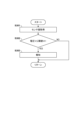
- FIG. 6 is a flowchart showing an example of processing performed by the idle stop ECU 102.
- This flowchart is periodically executed in parallel with the flowchart of FIG. 5, for example, when the engine 40 is automatically stopped based on the flowchart of FIG.
- the idle stop ECU 102 acquires a sensor value.
- the idle stop ECU 102 acquires the sensor value of the battery voltage sensor 108 .
- the idling stop ECU 102 proceeds to S303 if the battery voltage V is equal to or lower than the threshold Vt1, otherwise ends the flowchart.
- the idle stop ECU 102 compares the battery voltage V obtained in S301 with a preset threshold value Vt1.
- the threshold Vt1 is set to a value higher than the restart voltage V0.
- the idle stop ECU 102 notifies the rider to restart the engine 40.
- the notification unit 96 is an indicator and is lit while the engine 40 is automatically stopped, the idle stop ECU 102 may switch the notification unit 96 from lighting to blinking.
- notification to prompt the restart operation may be performed by an alarm sound or a voice message, and when the notification unit 96 is a display unit capable of displaying text, a text message may be notified to prompt the restart operation.
- FIG. 7 is a flowchart showing an example of processing performed by the power control ECU 101.
- FIG. 7 shows processing when the power supply control ECU 101 controls the power supply state of the straddle-type vehicle 10 while the engine 40 is automatically stopped.
- This flowchart is periodically executed in parallel with the flowcharts of FIGS. 5 and 6 when the engine 40 is automatically stopped based on the flowchart of FIG. 4, for example.
- the power supply control ECU 101 acquires various information. For example, the power supply control ECU 101 acquires sensor values of various sensors and information such as whether or not the idle stop ECU 102 has notified the rider.
- the power control ECU 101 proceeds to S403 if the idling stop ECU 102 has notified S303, otherwise the flow chart ends. For example, when the rider is notified in S303, the idling stop ECU 102 stores information to that effect in the storage device of the idling stop ECU 102 . Then, the power supply control ECU 101 acquires from the idle stop ECU 102 information about the presence/absence of notification to the rider via a network such as CAN.
- the power supply control ECU 101 confirms whether or not the rider has performed a restart operation, and if so, proceeds to S404, otherwise ends the flowchart.
- the restarting operation is, for example, an operation that performs step S205 in the flow chart of FIG.
- the power supply control ECU 101 advances to S405 if a predetermined condition is satisfied, otherwise ends the flowchart.
- the predetermined condition may be that the battery voltage V has dropped to a threshold Vt2 that is equal to or higher than the restart voltage V0 and lower than the threshold Vt1. In this case, the battery voltage V necessary for restarting can be ensured more reliably.
- the predetermined condition may be that a predetermined period of time has elapsed since the notification in S303. In this case, the conditions can be determined by simple processing.
- the power supply control ECU 101 switches the power supply state of the straddle-type vehicle 10 to a state with lower power consumption.
- a decrease in the battery voltage V is suppressed, so that the battery voltage V equal to or higher than the restart voltage V0 can be easily secured.
- the engine 40 is not restarted while the manual transmission 42 is in the in-gear state, so that the operation of the straddle-type vehicle 10 not intended by the rider is suppressed. can be done.
- the power supply control ECU 101 may switch the power supply state of the straddle-type vehicle 10 from a power-on state in which the ignition power supply and the accessory power supply are on to an accessory-on state in which only the accessory power supply is on. Further, for example, the power supply control ECU 101 may switch the power supply state of the straddle-type vehicle 10 from a power-on state in which the ignition power supply and the accessory power supply are on to a power-off state in which both of them are off.
- the rider manually restarts the engine 40 by operating a key or pressing a button at the timing when the engine 40 needs to be restarted. As a result, a drop in battery voltage V is suppressed until the engine 40 needs to be restarted after the power state is switched.
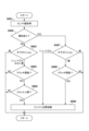
- FIG. 8 is a flow chart showing an example of processing performed by the idle stop ECU 102. As shown in FIG. FIG. 8 is a variation of the flowchart of FIG. 5, and shows processing when the idle stop ECU 102 restarts the engine 40 that has been automatically stopped based on a predetermined condition. More specifically, in the flowchart of FIG. 8, the conditions for restarting the engine 40 are changed when the notification of S303 of FIG. 6 is performed and when not. This flowchart is periodically executed, for example, when the engine 40 is automatically stopped based on the flowchart of FIG.
- the idle stop ECU 102 acquires a sensor value.
- the idle stop ECU 102 acquires sensor values of the throttle opening sensor 104 , the clutch detection sensor 105 and the gear position sensor 107 .
- the idling stop ECU 102 proceeds to S503 if the notification of S303 has been performed, otherwise proceeds to S507.
- the processor of the idling stop ECU 102 checks whether or not the information indicating that the notification of S303 has been made is stored in the storage device of the idling stop ECU 102 .
- S503 to S505 are processes when the notification of S303 is not performed, and are the same processes as S202 to S204. Further, S506 is the same processing as S205. Therefore, description of each step is omitted.
- the idle stop ECU 102 restarts the engine 40 in S506 if the manual transmission 42 is in neutral or 1st gear, the clutch 43 is released, and the throttle is open. Otherwise, the flowchart ends. .
- S507 and S508 are processes when the notification of S303 is performed.
- S507 if the gear position of the manual transmission 42 is neutral, the idle stop ECU 102 proceeds to S506 to restart the engine 40. If the gear position is 1st, the idle stop ECU 102 proceeds to S508. As a result, for example, when the rider switches the gear position of the manual transmission 42 from in gear (1st gear) to neutral, the engine 40 is restarted.
- the rider when the notification of S303 is performed, the rider performs an operation to allow the restart of the engine 40.
- the engine 40 is restarted when an operation is performed to prevent the occurrence of starting or the like.
- the convenience of the straddle-type vehicle 10 can be improved. Therefore, even if the condition for restarting from a normal automatic stop is that the throttle is open, the conditions for restarting are relaxed when there is the notification of S303, and the battery voltage V is reduced. Decrease can be suppressed.
- the threshold Vt2 for switching the power state may be changed according to environmental factors such as temperature.
- the threshold Vt2 may be set so that the threshold Vt2 is relatively high under low temperature conditions where the battery voltage V tends to drop.
- the threshold value Vt1 related to the notification to prompt the restart may be changed according to the temperature.
- the threshold Vt1 and the threshold Vt2 may be set based on factors that affect the performance of the battery 90, such as the usage period of the battery 90.
- the mode of notification by the notification unit 96 can be changed as appropriate.
- the state such as the color of the indicator or the manner of blinking may be changed according to the battery voltage V or the elapsed time from the notification.
- the blinking interval of the indicator may be shortened as the battery voltage V approaches the threshold Vt2.
- the straddle-type vehicle (for example, 10) of the above embodiment is an engine (e.g. 40) and a manual transmission 42 (for example) that shifts the rotation of the engine and transmits it to the driving wheels (for example, WR); idle stop control means (for example, 102) for performing idle stop control for automatically stopping the engine when an idle stop condition is satisfied;
- a straddle-type vehicle comprising a battery (for example, 90) that stores electric power necessary for starting the engine, Notification means ( For example, 96,S303) and After the notification, the power supply state of the straddle-type vehicle is changed to a first state with lower power consumption than when the notification was made, at least on condition that the restart operation of the engine has not been confirmed. and a power supply control means (for example, 102, S405).
- the rider when the battery voltage becomes equal to or less than the first threshold value, the rider is notified to restart the engine.
- the power state of the vehicle is set to the first state. Therefore, it is possible to easily secure the battery voltage necessary for restarting the engine while suppressing the operation of the vehicle that is not intended by the rider.
- the power supply control means changes the power supply state to the first state on the condition that the battery voltage drops to a second threshold value equal to or higher than the voltage value necessary for starting the engine and lower than the first threshold value. (eg S404, S405).
- the power state is switched based on the battery voltage, it is possible to more easily secure the battery voltage for restarting the engine.
- the power supply control means also sets the power supply state to the first state on condition that a predetermined time has passed since the notification (for example, S404, S405).
- switching of the power state can be determined by simple processing.
- the idling stop control means determines that the transmission is switched from the in-gear to the neutral after the notification by the notification means and before a condition for causing the power supply control means to change the power supply state to the first state is satisfied. If so, the automatic stop of the engine ends (for example, S507).
- the automatic stop of the engine ends, so the convenience of the vehicle can be improved.
- the idling stop control means controls the engine if the clutch is released after the notification by the notification means and before the power source control means sets the power source state to the first state. end the automatic stop of (for example, S506).
- the automatic stop of the engine ends, so the convenience of the vehicle can be improved.
- the first state is a state in which the ignition power source of the straddle-type vehicle is off.
- the idle stop control means terminates the automatic stop of the engine when the battery voltage becomes equal to or less than a third threshold during the automatic stop of the engine with the transmission in neutral.
- the drop in battery voltage can be suppressed by restarting the engine when the rider's unintended start or the like does not occur even if the engine is restarted.
Landscapes
- Engineering & Computer Science (AREA)
- Mechanical Engineering (AREA)
- Chemical & Material Sciences (AREA)
- Combustion & Propulsion (AREA)
- General Engineering & Computer Science (AREA)
- Business, Economics & Management (AREA)
- Emergency Management (AREA)
- Power Engineering (AREA)
- Transportation (AREA)
- Control Of Vehicle Engines Or Engines For Specific Uses (AREA)
- Charge And Discharge Circuits For Batteries Or The Like (AREA)
Priority Applications (4)
| Application Number | Priority Date | Filing Date | Title |
|---|---|---|---|
| CN202180101988.9A CN117881878A (zh) | 2021-09-30 | 2021-09-30 | 跨骑型车辆 |
| JP2023550919A JP7590590B2 (ja) | 2021-09-30 | 2021-09-30 | 鞍乗型車両 |
| DE112021008297.3T DE112021008297T5 (de) | 2021-09-30 | 2021-09-30 | Fahrzeug vom grätschsitz-typ |
| PCT/JP2021/036163 WO2023053353A1 (ja) | 2021-09-30 | 2021-09-30 | 鞍乗型車両 |
Applications Claiming Priority (1)
| Application Number | Priority Date | Filing Date | Title |
|---|---|---|---|
| PCT/JP2021/036163 WO2023053353A1 (ja) | 2021-09-30 | 2021-09-30 | 鞍乗型車両 |
Publications (1)
| Publication Number | Publication Date |
|---|---|
| WO2023053353A1 true WO2023053353A1 (ja) | 2023-04-06 |
Family
ID=85781769
Family Applications (1)
| Application Number | Title | Priority Date | Filing Date |
|---|---|---|---|
| PCT/JP2021/036163 Ceased WO2023053353A1 (ja) | 2021-09-30 | 2021-09-30 | 鞍乗型車両 |
Country Status (4)
| Country | Link |
|---|---|
| JP (1) | JP7590590B2 (https=) |
| CN (1) | CN117881878A (https=) |
| DE (1) | DE112021008297T5 (https=) |
| WO (1) | WO2023053353A1 (https=) |
Citations (4)
| Publication number | Priority date | Publication date | Assignee | Title |
|---|---|---|---|---|
| JPH0842387A (ja) * | 1994-07-30 | 1996-02-13 | Suzuki Motor Corp | 内燃機関の自動始動停止装置 |
| JP2010163879A (ja) * | 2009-01-13 | 2010-07-29 | Honda Motor Co Ltd | アイドルストップ制御装置 |
| JP2012251465A (ja) * | 2011-06-01 | 2012-12-20 | Honda Motor Co Ltd | アイドリングストップシステムおよびアイドリングストップの方法 |
| JP2016089742A (ja) * | 2014-11-06 | 2016-05-23 | 株式会社ケーヒン | 内燃機関用電子制御装置 |
Family Cites Families (1)
| Publication number | Priority date | Publication date | Assignee | Title |
|---|---|---|---|---|
| JP2010263879A (ja) | 2009-05-14 | 2010-11-25 | Keiji Arai | ひも止め具 |
-
2021
- 2021-09-30 CN CN202180101988.9A patent/CN117881878A/zh active Pending
- 2021-09-30 WO PCT/JP2021/036163 patent/WO2023053353A1/ja not_active Ceased
- 2021-09-30 DE DE112021008297.3T patent/DE112021008297T5/de active Pending
- 2021-09-30 JP JP2023550919A patent/JP7590590B2/ja active Active
Patent Citations (4)
| Publication number | Priority date | Publication date | Assignee | Title |
|---|---|---|---|---|
| JPH0842387A (ja) * | 1994-07-30 | 1996-02-13 | Suzuki Motor Corp | 内燃機関の自動始動停止装置 |
| JP2010163879A (ja) * | 2009-01-13 | 2010-07-29 | Honda Motor Co Ltd | アイドルストップ制御装置 |
| JP2012251465A (ja) * | 2011-06-01 | 2012-12-20 | Honda Motor Co Ltd | アイドリングストップシステムおよびアイドリングストップの方法 |
| JP2016089742A (ja) * | 2014-11-06 | 2016-05-23 | 株式会社ケーヒン | 内燃機関用電子制御装置 |
Also Published As
| Publication number | Publication date |
|---|---|
| DE112021008297T5 (de) | 2024-07-25 |
| JPWO2023053353A1 (https=) | 2023-04-06 |
| CN117881878A (zh) | 2024-04-12 |
| JP7590590B2 (ja) | 2024-11-26 |
Similar Documents
| Publication | Publication Date | Title |
|---|---|---|
| JP5750020B2 (ja) | 自動二輪車 | |
| TWI373554B (https=) | ||
| US20200290699A1 (en) | Parking brake apparatus for saddled vehicle | |
| TWI654107B (zh) | 車輛 | |
| JP5750019B2 (ja) | 自動二輪車 | |
| TWI686533B (zh) | 引擎起動控制裝置 | |
| JP7590590B2 (ja) | 鞍乗型車両 | |
| JP2013083243A (ja) | 自動二輪車 | |
| JP5720383B2 (ja) | 自動二輪車用アイドリングストップ制御装置およびこれを備える自動二輪車 | |
| JP6582441B2 (ja) | 自動二輪車のアイドリングストップ制御装置 | |
| JP6701389B2 (ja) | 鞍乗り型車両の運転状態表示装置 | |
| JP7590589B2 (ja) | 鞍乗型車両 | |
| JP7578842B2 (ja) | 鞍乗型車両 | |
| JP6097191B2 (ja) | アイドルストップ制御装置 | |
| FR2955072A1 (fr) | Procede d'information du conducteur d'un vehicule muni d'un systeme d'arret et de redemarrage automatique du moteur, en cas de redemarrage | |
| JP7630631B2 (ja) | 鞍乗型車両 | |
| JP7725709B2 (ja) | 鞍乗型車両 | |
| JP2016156347A (ja) | 自動二輪車のアイドリングストップ制御装置 | |
| JP7590481B2 (ja) | 鞍乗型車両及び制御方法 | |
| JP2014199041A (ja) | 自動二輪車の制御装置 | |
| JP2013072414A (ja) | 自動二輪車 | |
| JP2005139912A (ja) | 自動アイドル停止車両 | |
| JP2006123801A (ja) | 自動車の暴走防止装置 |
Legal Events
| Date | Code | Title | Description |
|---|---|---|---|
| 121 | Ep: the epo has been informed by wipo that ep was designated in this application |
Ref document number: 21959391 Country of ref document: EP Kind code of ref document: A1 |
|
| WWE | Wipo information: entry into national phase |
Ref document number: 202180101988.9 Country of ref document: CN |
|
| WWE | Wipo information: entry into national phase |
Ref document number: 2023550919 Country of ref document: JP |
|
| WWE | Wipo information: entry into national phase |
Ref document number: 202417016439 Country of ref document: IN |
|
| WWE | Wipo information: entry into national phase |
Ref document number: 2401001774 Country of ref document: TH |
|
| WWE | Wipo information: entry into national phase |
Ref document number: 112021008297 Country of ref document: DE |
|
| 122 | Ep: pct application non-entry in european phase |
Ref document number: 21959391 Country of ref document: EP Kind code of ref document: A1 |