WO2023047772A1 - 電池および接合方法 - Google Patents
電池および接合方法 Download PDFInfo
- Publication number
- WO2023047772A1 WO2023047772A1 PCT/JP2022/027848 JP2022027848W WO2023047772A1 WO 2023047772 A1 WO2023047772 A1 WO 2023047772A1 JP 2022027848 W JP2022027848 W JP 2022027848W WO 2023047772 A1 WO2023047772 A1 WO 2023047772A1
- Authority
- WO
- WIPO (PCT)
- Prior art keywords
- radial direction
- electrode
- region
- roller
- electrode group
- Prior art date
- Legal status (The legal status is an assumption and is not a legal conclusion. Google has not performed a legal analysis and makes no representation as to the accuracy of the status listed.)
- Ceased
Links
Images


Classifications
-
- H—ELECTRICITY
- H01—ELECTRIC ELEMENTS
- H01M—PROCESSES OR MEANS, e.g. BATTERIES, FOR THE DIRECT CONVERSION OF CHEMICAL ENERGY INTO ELECTRICAL ENERGY
- H01M10/00—Secondary cells; Manufacture thereof
- H01M10/05—Accumulators with non-aqueous electrolyte
- H01M10/058—Construction or manufacture
- H01M10/0587—Construction or manufacture of accumulators having only wound construction elements, i.e. wound positive electrodes, wound negative electrodes and wound separators
-
- H—ELECTRICITY
- H01—ELECTRIC ELEMENTS
- H01M—PROCESSES OR MEANS, e.g. BATTERIES, FOR THE DIRECT CONVERSION OF CHEMICAL ENERGY INTO ELECTRICAL ENERGY
- H01M10/00—Secondary cells; Manufacture thereof
- H01M10/04—Construction or manufacture in general
-
- H—ELECTRICITY
- H01—ELECTRIC ELEMENTS
- H01M—PROCESSES OR MEANS, e.g. BATTERIES, FOR THE DIRECT CONVERSION OF CHEMICAL ENERGY INTO ELECTRICAL ENERGY
- H01M10/00—Secondary cells; Manufacture thereof
- H01M10/04—Construction or manufacture in general
- H01M10/0431—Cells with wound or folded electrodes
-
- H—ELECTRICITY
- H01—ELECTRIC ELEMENTS
- H01M—PROCESSES OR MEANS, e.g. BATTERIES, FOR THE DIRECT CONVERSION OF CHEMICAL ENERGY INTO ELECTRICAL ENERGY
- H01M10/00—Secondary cells; Manufacture thereof
- H01M10/05—Accumulators with non-aqueous electrolyte
- H01M10/052—Li-accumulators
-
- H—ELECTRICITY
- H01—ELECTRIC ELEMENTS
- H01M—PROCESSES OR MEANS, e.g. BATTERIES, FOR THE DIRECT CONVERSION OF CHEMICAL ENERGY INTO ELECTRICAL ENERGY
- H01M50/00—Constructional details or processes of manufacture of the non-active parts of electrochemical cells other than fuel cells, e.g. hybrid cells
- H01M50/50—Current conducting connections for cells or batteries
- H01M50/531—Electrode connections inside a battery casing
- H01M50/533—Electrode connections inside a battery casing characterised by the shape of the leads or tabs
-
- H—ELECTRICITY
- H01—ELECTRIC ELEMENTS
- H01M—PROCESSES OR MEANS, e.g. BATTERIES, FOR THE DIRECT CONVERSION OF CHEMICAL ENERGY INTO ELECTRICAL ENERGY
- H01M50/00—Constructional details or processes of manufacture of the non-active parts of electrochemical cells other than fuel cells, e.g. hybrid cells
- H01M50/50—Current conducting connections for cells or batteries
- H01M50/531—Electrode connections inside a battery casing
- H01M50/538—Connection of several leads or tabs of wound or folded electrode stacks
-
- Y—GENERAL TAGGING OF NEW TECHNOLOGICAL DEVELOPMENTS; GENERAL TAGGING OF CROSS-SECTIONAL TECHNOLOGIES SPANNING OVER SEVERAL SECTIONS OF THE IPC; TECHNICAL SUBJECTS COVERED BY FORMER USPC CROSS-REFERENCE ART COLLECTIONS [XRACs] AND DIGESTS
- Y02—TECHNOLOGIES OR APPLICATIONS FOR MITIGATION OR ADAPTATION AGAINST CLIMATE CHANGE
- Y02E—REDUCTION OF GREENHOUSE GAS [GHG] EMISSIONS, RELATED TO ENERGY GENERATION, TRANSMISSION OR DISTRIBUTION
- Y02E60/00—Enabling technologies; Technologies with a potential or indirect contribution to GHG emissions mitigation
- Y02E60/10—Energy storage using batteries
-
- Y—GENERAL TAGGING OF NEW TECHNOLOGICAL DEVELOPMENTS; GENERAL TAGGING OF CROSS-SECTIONAL TECHNOLOGIES SPANNING OVER SEVERAL SECTIONS OF THE IPC; TECHNICAL SUBJECTS COVERED BY FORMER USPC CROSS-REFERENCE ART COLLECTIONS [XRACs] AND DIGESTS
- Y02—TECHNOLOGIES OR APPLICATIONS FOR MITIGATION OR ADAPTATION AGAINST CLIMATE CHANGE
- Y02P—CLIMATE CHANGE MITIGATION TECHNOLOGIES IN THE PRODUCTION OR PROCESSING OF GOODS
- Y02P70/00—Climate change mitigation technologies in the production process for final industrial or consumer products
- Y02P70/50—Manufacturing or production processes characterised by the final manufactured product
Definitions
- the present disclosure relates to a battery including an electrode group and a current collector, and a method for joining the electrode group and the current collector.
- Patent Literature 1 discloses a method of forming a flat welding surface by bending an end portion of an electrode group and welding the welding surface to a current collector plate.
- the electrode active material layer may peel off or the like, which may lead to a deterioration in the quality of the battery.
- the present disclosure has been made in view of such circumstances, and one of its purposes is to provide a technique for improving the quality of batteries.
- a certain aspect of the present disclosure is a battery.
- This battery includes a wound electrode group in which separators and electrode plates are laminated and wound, and a collector plate.
- the ends of a plurality of electrode plates arranged in the radial direction are bent in the radial direction, and the bent ends are joined to the current collector plate.
- the bent end has a first region that bends to one side in the radial direction and a second region that bends to the other side in the radial direction from the tip of the first region.
- Another aspect of the present disclosure is a method for joining a wound electrode group in which separators and electrode plates are laminated and wound, and a current collector plate.
- a radially rotatable roller of the electrode group is pressed against the ends of the plurality of electrode plates arranged in the radial direction, and the rollers are displaced to one side in the radial direction to move the plurality of ends to one side. While bending, the roller is rotated so that the contact portion of the roller with the end portion is displaced to the other side in the radial direction, and the tips of the plurality of end portions are bent to the other side, and the bent plurality of end portions and the current collector plate including joining
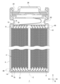
- FIG. 1 is a cross-sectional view of a battery;
- FIG. FIG. 2A is a diagram showing a process of forming an electrode group.
- FIG. 2B is a diagram showing the processing steps of the electrode group.
- FIGS. 3A to 3C are diagrams showing how the ends of the electrode plate are deformed in the process of processing the electrode group.
- FIG. 4 is a diagram showing a state after the electrode group and the current collector plate are joined;
- FIG. 1 is a cross-sectional view of the battery 1.
- the battery 1 is, for example, a rechargeable secondary battery such as a lithium ion battery, a nickel-hydrogen battery, a nickel-cadmium battery.
- a battery 1 as an example has a structure in which an electrode group 2 is housed in an outer can 4 together with an electrolytic solution (not shown).
- the electrode group 2 has, for example, a cylindrical shape, and has a wound structure in which a strip-shaped first electrode plate 6 and a strip-shaped second electrode plate 8 are laminated with a strip-shaped separator 10 interposed therebetween and spirally wound. (see also FIG. 2(A)).
- the first electrode plate 6 is a positive plate and the second electrode plate 8 is a negative plate.
- the separator 10 is made of, for example, a microporous film made of polypropylene resin or the like.
- the first electrode plate 6 and the second electrode plate 8 have a structure in which an electrode active material layer is laminated on a current collector.
- the current collector is made of aluminum foil or the like for the positive electrode, and is made of copper foil or the like for the negative electrode.
- the electrode active material layer can be formed by applying an electrode mixture to the surface of the current collector with a known coating device, drying and rolling. The electrode mixture is obtained by kneading materials such as an electrode active material, a binder, and a conductive material into a dispersion medium and dispersing them uniformly.
- the electrode active material is lithium cobalt oxide, lithium iron phosphate, or the like for the positive electrode, and graphite or the like for the negative electrode.
- the first electrode plate 6 has a first uncoated portion 12 where the electrode mixture is not coated at one end in the width direction A (the direction intersecting with the longitudinal direction of the band).
- the first uncoated portion 12 is an exposed portion of the current collector of the first electrode plate 6 where the electrode active material layer is not laminated.
- the second electrode plate 8 has a second uncoated portion 14 on which the electrode mixture is not coated at the other side in the width direction A, that is, at the end opposite to the side where the first uncoated portion 12 protrudes. have The second uncoated portion 14 is an exposed portion of the current collector of the second electrode plate 8 where the electrode active material layer is not laminated.
- the electrode group 2 has a structure in which the first electrode plate 6 and the second electrode plate 8 are wound. Therefore, a plurality of ends in the width direction A of the first electrode plate 6 and the second electrode plate 8 are aligned in the radial direction B of the electrode group 2 . Therefore, the electrode group 2 has a plurality of first uncoated portions 12 arranged in the radial direction B and a plurality of second uncoated portions 14 arranged in the radial direction B. As shown in FIG.
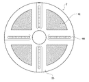
- the electrode group 2 has a first joint region 46 in which the end portions of the plurality of first electrode plates 6 arranged in the radial direction B, that is, the first uncoated portions 12 are bent in the radial direction B.
- the electrode group 2 as an example has a plurality of first bonding regions 46 spaced apart at predetermined intervals in the circumferential direction of the electrode group 2 .
- the electrode group 2 has four first bonding regions 46 spaced circumferentially by 90°.
- the electrode group 2 has a second joint region 48 in which the end portions of the plurality of second electrode plates 8 arranged in the radial direction B, that is, the second uncoated portions 14 are bent in the radial direction B.
- the electrode group 2 as an example has a plurality of second bonding regions 48 spaced apart at predetermined intervals in the circumferential direction of the electrode group 2 .
- the electrode group 2 has four second bonding regions 48 spaced circumferentially by 90°.
- the electrode group 2 may have only one of the first bonding region 46 and the second bonding region 48 .
- Each end of the first electrode plate 6 bent at the first bonding area 46 has a first area 74 and a second area 76 .
- the first region 74 bends to one side in the radial direction B, and the second region 76 bends to the other side in the radial direction B from the tip of the first region 74 .
- Each end of the second electrode plate 8 bent at the second bonding area 48 similarly has a first area 74 and a second area 76 .
- the first region 74 bends to one side in the radial direction B, and the second region 76 bends to the other side in the radial direction B from the tip of the first region 74 .
- one side in the radial direction B is the inner side in the radial direction B
- the other side in the radial direction B is the outer side in the radial direction B. That is, the first region 74 is bent toward the winding center C of the electrode group 2 on the center side in the width direction A relative to the second region 76 .
- the winding center C is, for example, the geometric center of the outer shape of the electrode group 2 viewed from the width direction A, in other words, the geometric center of the outer shape of the projected shape of the electrode group 2 in the width direction A.
- the second region 76 bends outward in the radial direction B from the outer end portion in the width direction A of the first region 74 and extends. Note that one side in the radial direction B may be the outer side in the radial direction B, and the other side in the radial direction B may be the inner side in the radial direction B.
- a first collector plate 20 is arranged on the side of the electrode group 2 where the first uncoated portion 12 protrudes.
- the first collector plate 20 is made of, for example, aluminum.
- the bent end portions of the plurality of first electrode plates 6 in the first joint regions 46 are in surface contact with the first collector plate 20 .
- the contact area between each first uncoated portion 12 and the first collector plate 20 increases.
- laser welding or the like is applied to the position where the first joint region 46 and the first collector plate 20 overlap.
- the first electrode plate 6 and the first collector plate 20 of each winding layer are joined to each other.
- the second region 76 is joined to the first collector plate 20 .
- a second collector plate 22 is arranged on the side of the electrode group 2 where the second uncoated portion 14 protrudes.
- the second collector plate 22 is made of, for example, copper, nickel, nickel-plated copper, or nickel-plated iron.
- the ends of the plurality of second electrode plates 8 bent at the second joint regions 48 are in surface contact with the second collector plate 22 .
- the contact area between each second uncoated portion 14 and the second current collector plate 22 increases.
- laser welding or the like is applied to the position where the second joint region 48 and the second collector plate 22 overlap.
- the second electrode plate 8 and the second collector plate 22 of each winding layer are joined to each other.
- the second region 76 is joined to the second collector plate 22 .
- the electrode group 2 to which the first current collector plate 20 and the second current collector plate 22 are joined is housed in the bottomed cylindrical outer can 4 together with the electrolytic solution.
- the outer can 4 is made of, for example, copper, nickel, iron, or an alloy thereof.
- the second collector plate 22 is joined to the inner bottom surface of the outer can 4 by welding or the like.
- the first collector plate 20 is joined by welding or the like to a sealing plate 26 made of the same metal as the outer can 4 .
- the sealing plate 26 is fitted into the opening of the outer can 4 with an insulating gasket 24 interposed therebetween. As a result, the electrode group 2 and the electrolytic solution are sealed inside the outer can 4 .
- a method for joining the electrode group 2 and the current collector plate will be described.
- a method of joining the electrode group 2 and the current collector will be described below, taking the joining of the first joint region 46 and the first collector plate 20 as an example.
- the bonding of the second bonding region 48 and the second current collector plate 22 is the same as that of the first bonding region 46 . Note that only one of the first bonding region 46 and the second bonding region 48 may be formed by the method according to the present embodiment and bonded to the current collector plate.
- FIG. 2(A) is a diagram showing the process of forming the electrode group 2.
- FIG. 2A illustration of the first unapplied portion 12 and the second unapplied portion 14 is omitted.
- FIG. 2B is a diagram showing the processing steps of the electrode group 2.
- FIGS. 3A to 3C are diagrams showing how the ends of the electrode plates are deformed in the process of processing the electrode group 2.
- FIG. 4 is a diagram showing the state after the electrode group 2 and the current collector plate are joined.
- strip-shaped first electrode plates 6, second electrode plates 8, and separators 10 are prepared. Then, the separator 10, the first electrode plate 6, the separator 10 and the second electrode plate 8 are laminated in this order. The obtained laminate is spirally wound to form the wound electrode group 2 .
- the processing device 28 includes a stage 30 , a pair of processing tools 78 , a roller rotating mechanism 80 and a frame 36 .
- the stage 30 as an example has a circular groove 30b into which the end of the electrode group 2 is fitted, and the electrode group 2 is fixed by fitting the end into the groove 30b.
- the method for fixing the electrode group 2 is not particularly limited.
- the electrode group 2 is oriented such that the winding center C extends in the normal direction of the stage 30 .
- the electrode group 2 shown in FIG. 2B is oriented such that the first unapplied portion 12 faces the opposite side of the stage 30 .
- the stage 30 can rotate the electrode group 2 around the winding center C. As shown in FIG.
- a pair of processing tools 78 are arranged at positions facing the stage 30 with the electrode group 2 interposed therebetween.
- Each processing tool 78 is supported by the frame 36 so as to be slidable in the radial direction B.
- the frame 36 supports a driving portion (not shown) for sliding the processing tools 78 in the radial direction B.
- the drive section can be configured by, for example, a motor, a cam mechanism, or the like.
- Each processing tool 78 has a roller 82 facing the electrode group 2 .
- Each roller 82 is supported by each processing tool 78 so as to be rotatable in the radial direction B. As shown in FIG.
- Each roller 82 is pressed against the end portions of the plurality of electrode plates (the first uncoated portions 12 in FIG. 2(B)).
- the roller rotation mechanism 80 is supported by the frame 36.
- a roller rotation mechanism 80 as an example is configured by a mechanism similar to a rack and pinion, and has a rack rail 84 , a first pinion 86 and a second pinion 88 .
- the rack rail 84 extends in the radial direction B while being supported by the frame 36 .
- the first pinion 86 is meshed with the rack rail 84 and supported by the processing tool 78 .
- the second pinion 88 is meshed with the first pinion 86 and supported by the processing tool 78 .
- the second pinion 88 and the roller 82 are connected by a rotating shaft 90 extending in a direction orthogonal to the radial direction B. As shown in FIG.
- a first pinion 86 and a second pinion 88 are provided for the rollers 82 of each processing tool 78 , and the rack rails 84 are shared by the rollers 82 .
- Each processing tool 78 slides toward one side in the radial direction B while the rollers 82 are pressed against the plurality of first unapplied portions 12 arranged in the radial direction B. As a result, the entire roller 82 is displaced to one side in the radial direction B. As shown in FIG. In addition, in each roller 82, the contact portion of the roller 82 with the end portion of the electrode plate (the first uncoated portion 12 in FIG. 2B), that is, the portion of the roller 82 facing the stage 30 side Rotate to displace to the side.
- the roller 82 is pressed against the first unapplied portion 12 while each processing tool 78 is positioned at the outermost end in the radial direction B. Then, each processing tool 78 slides inward in the radial direction B. As shown in FIG. As a result, the entire roller 82 is displaced inward in the radial direction B. As shown in FIG. Due to this displacement of the roller 82, the end of the first unapplied portion 12 is bent inward to form a first region 74, as shown in FIG. 3(A).
- the first pinion 86 and the second pinion 88 supported by each processing tool 78 are also displaced inward in the radial direction B together with the roller 82 .
- the first pinion 86 moves along the rack rail 84 and rotates due to meshing with the rack rail 84 .
- the first pinion 86 rotates so that the portion facing the stage 30 side is displaced inward in the radial direction B.
- the second pinion 88 rotates by meshing with the first pinion 86 .
- the second pinion 88 rotates in a direction opposite to that of the first pinion 86 , that is, the portion facing the stage 30 side is displaced outward in the radial direction B.
- the rotational torque of the second pinion 88 is transmitted to the roller 82 via the rotating shaft 90, thereby rotating the roller 82 as well.
- Each roller 82 rotates so that the contact portion of the roller 82 with the first unapplied portion 12 , that is, the portion of the roller 82 facing the stage 30 side is displaced outward in the radial direction B. Friction is generated between the peripheral surface of the roller 82 and the first unapplied portion 12 . Therefore, by rotating the roller 82, as shown in FIG. 3B, the tip of the first unapplied portion 12 is bent outward in the radial direction B to form the second region 76 at the tip of the first region 74 be done.
- roller 82 is rotated at a faster speed than when the roller 82 as a whole is displaced to one side in the radial direction B by sliding the processing tool 78 and is driven by contact with the ends of a plurality of electrode plates. This makes it easier to raise the tip of the first region 74 .
- roller 82 is made of resin.
- the frictional force against the first unapplied portion 12 and the second unapplied portion 14 made of metal can be increased. Therefore, it is possible to make it easier to form the second region 76 .
- Urethane is exemplified as the resin forming the roller 82 .
- Such active rotation of the rollers 82 can be realized by adjusting the reduction ratio (gear ratio) of the rack rail 84, the first pinion 86 and the second pinion 88. If the roller rotation mechanism 80 is not provided, each roller 82 is driven to rotate as the processing tool 78 slides due to friction with the first uncoated portion 12 . Assuming that the rotation speed of the roller 82 at this time (the amount of rotation of the roller 82 per unit displacement of the processing tool 78) is 1, the rotation speed of the roller rotation mechanism 80 is greater than 1, for example, 1.25 or more. The rollers 82 are rotated as follows.
- each processing tool 78 is further slid inward in the radial direction B to form the first regions 74 in the adjacent first unapplied portions 12 . Thereafter, this operation is repeated to form the first region 74 and the second region 76 at the tip of the first unapplied portion 12 in the entire radial direction B. As shown in FIG. That is, each first unapplied portion 12 is pressed in a straight line passing through the winding center C when viewed from the extending direction of the winding center C, thereby forming the first region 74 and the second region 76 .
- the electrode group 2 is rotated about the winding center C by 90°, and the pair of machining tools 78 are moved linearly through the winding center C again.
- the first unapplied portion 12 is pressed.
- the first joint regions 46 are formed in a cross shape in the electrode group 2 .
- the first collector plate 20 is pressed against the electrode group 2 . Then, as shown in FIG. 4 , laser welding or the like is applied to the position where the first joint region 46 and the first collector plate 20 overlap to form a joint 44 . As a result, the plurality of first unapplied portions 12 bent at the first bonding regions 46 and the first collector plate 20 are bonded.
- the electrode group 2 to which the first collector plate 20 is joined is oriented and fixed to the stage 30 such that the second unapplied portion 14 faces the opposite side of the stage 30 . Then, the second unapplied portion 14 is processed by the pair of processing tools 78 . As a result, a cross-shaped second bonding region 48 is formed in the electrode group 2 . Then, the plurality of second non-applied portions 14 bent in the second joint regions 48 and the second collector plate 22 are joined by laser welding or the like.
- the electrode group 2 to which the first current collector plate 20 and the second current collector plate 22 are joined is housed in the outer can 4 together with the electrolytic solution.
- processing such as joining the second collector plate 22 and the outer can 4, joining the first collector plate 20 and the sealing plate 26, and fitting the sealing plate 26 into the opening of the outer can 4 is performed.
- a battery 1 is obtained.
- the order of processing such as bonding of each part, accommodation in the outer can 4, fitting of the sealing plate 26, etc. can be changed as appropriate.
- the sealing plate 26 or the like is provided with an injection port, the electrolytic solution may be injected into the outer can 4 after the sealing plate 26 is fitted into the opening of the outer can 4 .
- the ends of the plurality of electrode plates arranged in the radial direction B are bent in the radial direction B, and the bent ends are the current collector plates. is spliced to The bent end has a first region 74 that bends to one side in the radial direction B and a second region 76 that bends to the other side in the radial direction B from the tip of the first region 74 .
- a load is applied to the end of the electrode plate when the collector plate is pressed against the electrode group 2 .
- the load concentrates on the portion of the electrode plate where the electrode active material layer is laminated, and buckling occurs in this portion, causing peeling of the electrode active material layer. could have occurred.
- a second region 76 is provided at the tip of the first region 74 and folded back to the opposite side, and the current collecting plate is pressed against this second region 76 .
- the load applied to the electrode plate when the current collector plate is pressed can be concentrated on the region including the connecting portion between the first region 74 and the second region 76 .
- peeling of the electrode active material layer can be suppressed, and the quality of the battery 1 can be improved.
- the first region 74 is tilted inward in the radial direction B, and the second region 76 is tilted outward in the radial direction B.
- the first region 74 and the second region 76 can be formed more easily and stably than when the first region 74 is tilted outward and the second region 76 is tilted inward. Therefore, the bonding stability between the electrode plate and the current collector plate of each winding layer can be enhanced, and the quality of the battery 1 can be improved.
- a roller 82 rotatable in the radial direction B is pressed against the ends of the plurality of electrode plates, and the roller 82 is moved in one direction in the radial direction B.
- the rollers 82 are rotated so that the contact portions of the rollers 82 with the ends of the electrode plates are displaced to the other side in the radial direction B to bend the plurality of ends to one side. Bending the tip to the other side and joining the bent ends and the current collector plate are included.
- the first region 74 can be formed at the edge of the electrode plate. Further, by rotating the roller 82 together with the slide, the second area 76 can be formed at the tip of the first area 74 . Therefore, according to the present embodiment, the first region 74 and the second region 76 can be easily formed at the ends of the electrode plate.
- the roller 82 of the present embodiment is rotated at a faster speed than when the roller 82 is displaced to one side in the radial direction B and driven by contact with the end of the electrode plate.
- the tip of the first region 74 can be easily folded back. Therefore, since the second region 76 can be formed more easily, the quality of the battery 1 can be improved.
- the roller 82 is made of resin. As a result, the frictional force against the non-applied portion made of metal foil can be increased compared to the case where the roller 82 is made of metal, and the second region 76 can be formed more easily. Therefore, the quality of the battery 1 can be improved.
- Embodiments may be specified by items described below.
- a wound electrode group (2) in which a separator (10) and electrode plates (6, 8) are laminated and wound; and a current collector plate (20, 22),
- the ends of a plurality of electrode plates (6, 8) arranged in the radial direction (B) are bent in the radial direction (B), and the bent ends are current collector plates (20, 22).
- the bent ends consist of a first region (74) that bends to one side in the radial direction (B) and a second region (76) that bends from the tip of the first region (74) to the other side in the radial direction (B). has Battery (1).
- One side is the inner side in the radial direction (B); the other side is radially outward (B), A battery (1) according to the first item.
- the roller (82) is displaced to one side of (B) to bend the plurality of ends to one side, and the roller (82) is displaced to the other side in the radial direction (B) of the contact portion with the end of the roller (82). Rotate and bend the tip of the plurality of ends to the other side, joining the bent ends and the current collector (20, 22); Joining method.
- the roller (82) is caused to rotate at a higher speed when displaced to one side than when driven by contact with the ends; The joining method according to the third item.
- the ends of the electrode plates (6, 8) are made of metal,
- the roller (82) is made of resin, The joining method according to the third item or the fourth item.
- the present disclosure can be used for a battery including an electrode group and a current collector and a method for joining the electrode group and the current collector.
- 1 battery 2 electrode group, 6 first electrode plate, 8 second electrode plate, 10 separator, 20 first current collector, 22 second current collector, 46 first junction area, 48 second junction area, 74 second 1 region, 76 second region, 82 rollers.
Landscapes
- Chemical & Material Sciences (AREA)
- Chemical Kinetics & Catalysis (AREA)
- Electrochemistry (AREA)
- General Chemical & Material Sciences (AREA)
- Engineering & Computer Science (AREA)
- Manufacturing & Machinery (AREA)
- Secondary Cells (AREA)
- Connection Of Batteries Or Terminals (AREA)
Priority Applications (3)
| Application Number | Priority Date | Filing Date | Title |
|---|---|---|---|
| CN202280062801.3A CN117999699A (zh) | 2021-09-21 | 2022-07-15 | 电池及接合方法 |
| JP2023549391A JPWO2023047772A1 (https=) | 2021-09-21 | 2022-07-15 | |
| US18/692,768 US20240380010A1 (en) | 2021-09-21 | 2022-07-15 | Battery and joining method |
Applications Claiming Priority (2)
| Application Number | Priority Date | Filing Date | Title |
|---|---|---|---|
| JP2021-152940 | 2021-09-21 | ||
| JP2021152940 | 2021-09-21 |
Publications (1)
| Publication Number | Publication Date |
|---|---|
| WO2023047772A1 true WO2023047772A1 (ja) | 2023-03-30 |
Family
ID=85720462
Family Applications (1)
| Application Number | Title | Priority Date | Filing Date |
|---|---|---|---|
| PCT/JP2022/027848 Ceased WO2023047772A1 (ja) | 2021-09-21 | 2022-07-15 | 電池および接合方法 |
Country Status (4)
| Country | Link |
|---|---|
| US (1) | US20240380010A1 (https=) |
| JP (1) | JPWO2023047772A1 (https=) |
| CN (1) | CN117999699A (https=) |
| WO (1) | WO2023047772A1 (https=) |
Cited By (2)
| Publication number | Priority date | Publication date | Assignee | Title |
|---|---|---|---|---|
| WO2025116021A1 (ja) * | 2023-11-30 | 2025-06-05 | パナソニックIpマネジメント株式会社 | 蓄電装置 |
| WO2025143146A1 (ja) * | 2023-12-27 | 2025-07-03 | パナソニックIpマネジメント株式会社 | 蓄電装置及び蓄電装置の製造方法 |
Citations (6)
| Publication number | Priority date | Publication date | Assignee | Title |
|---|---|---|---|---|
| JP2002170547A (ja) * | 2000-12-04 | 2002-06-14 | Yuasa Corp | 密閉形電池 |
| JP2003022842A (ja) * | 2001-05-02 | 2003-01-24 | Ngk Insulators Ltd | リチウム二次電池 |
| JP2008066075A (ja) * | 2006-09-06 | 2008-03-21 | Hitachi Ltd | 非水電解質二次電池 |
| JP2010257851A (ja) * | 2009-04-27 | 2010-11-11 | Toyota Motor Corp | 電池の製造方法 |
| JP2019125565A (ja) * | 2018-01-19 | 2019-07-25 | 株式会社豊田自動織機 | 蓄電モジュール及びその製造方法 |
| WO2021024734A1 (ja) * | 2019-08-08 | 2021-02-11 | 株式会社村田製作所 | 二次電池、電池パック、電子機器、電動工具及び電動車両 |
-
2022
- 2022-07-15 JP JP2023549391A patent/JPWO2023047772A1/ja active Pending
- 2022-07-15 US US18/692,768 patent/US20240380010A1/en active Pending
- 2022-07-15 CN CN202280062801.3A patent/CN117999699A/zh active Pending
- 2022-07-15 WO PCT/JP2022/027848 patent/WO2023047772A1/ja not_active Ceased
Patent Citations (6)
| Publication number | Priority date | Publication date | Assignee | Title |
|---|---|---|---|---|
| JP2002170547A (ja) * | 2000-12-04 | 2002-06-14 | Yuasa Corp | 密閉形電池 |
| JP2003022842A (ja) * | 2001-05-02 | 2003-01-24 | Ngk Insulators Ltd | リチウム二次電池 |
| JP2008066075A (ja) * | 2006-09-06 | 2008-03-21 | Hitachi Ltd | 非水電解質二次電池 |
| JP2010257851A (ja) * | 2009-04-27 | 2010-11-11 | Toyota Motor Corp | 電池の製造方法 |
| JP2019125565A (ja) * | 2018-01-19 | 2019-07-25 | 株式会社豊田自動織機 | 蓄電モジュール及びその製造方法 |
| WO2021024734A1 (ja) * | 2019-08-08 | 2021-02-11 | 株式会社村田製作所 | 二次電池、電池パック、電子機器、電動工具及び電動車両 |
Cited By (2)
| Publication number | Priority date | Publication date | Assignee | Title |
|---|---|---|---|---|
| WO2025116021A1 (ja) * | 2023-11-30 | 2025-06-05 | パナソニックIpマネジメント株式会社 | 蓄電装置 |
| WO2025143146A1 (ja) * | 2023-12-27 | 2025-07-03 | パナソニックIpマネジメント株式会社 | 蓄電装置及び蓄電装置の製造方法 |
Also Published As
| Publication number | Publication date |
|---|---|
| US20240380010A1 (en) | 2024-11-14 |
| CN117999699A (zh) | 2024-05-07 |
| JPWO2023047772A1 (https=) | 2023-03-30 |
Similar Documents
| Publication | Publication Date | Title |
|---|---|---|
| JP4402134B2 (ja) | 積層型二次電池およびその製造方法 | |
| EP2124285B1 (en) | Wound type electrode battery, and its manufacturing method | |
| JP6038803B2 (ja) | 渦巻電極体を備えた電池及びその製造方法 | |
| US10559809B2 (en) | Power storage device | |
| WO2023047772A1 (ja) | 電池および接合方法 | |
| KR102499324B1 (ko) | 이차전지용 권취장치 | |
| EP2133942A1 (en) | Secondary battery and method for manufacturing secondary battery | |
| JP2014041724A (ja) | 蓄電装置、及び電極組立体の製造方法 | |
| JPWO2010087384A1 (ja) | 電池及び電池の製造方法と、電池における巻芯の製造方法及び巻芯製造装置並びに巻芯 | |
| JP6045286B2 (ja) | 円筒形蓄電素子 | |
| JP5578118B2 (ja) | 電池および電池の製造方法 | |
| WO2017010046A1 (ja) | 捲回型電池 | |
| JP3628899B2 (ja) | 積層型電池 | |
| JP2016167416A (ja) | 蓄電装置のセパレータ収納式電極体、蓄電装置の電極組立体、及び蓄電装置の製造装置 | |
| JP5341091B2 (ja) | 電気エネルギー貯蔵体の製造方法及び装置 | |
| JP3733403B2 (ja) | 電極捲回型電池 | |
| JP6505943B2 (ja) | 二次電池 | |
| JP2026053730A (ja) | 電極群および接合方法 | |
| JP2021051924A (ja) | 蓄電装置の製造方法、及び蓄電装置 | |
| WO2023176557A1 (ja) | 製造装置 | |
| WO2023037763A1 (ja) | 電池の製造方法および電池 | |
| JP2001216997A (ja) | 電池用渦巻状電極群およびそれを用いた電池 | |
| WO2023032454A1 (ja) | 電池および接合方法 | |
| JP6863192B2 (ja) | 組電池の製造方法 | |
| WO2016158398A1 (ja) | 角形二次電池およびその製造方法 |
Legal Events
| Date | Code | Title | Description |
|---|---|---|---|
| 121 | Ep: the epo has been informed by wipo that ep was designated in this application |
Ref document number: 22872528 Country of ref document: EP Kind code of ref document: A1 |
|
| WWE | Wipo information: entry into national phase |
Ref document number: 2023549391 Country of ref document: JP |
|
| WWE | Wipo information: entry into national phase |
Ref document number: 18692768 Country of ref document: US Ref document number: 202280062801.3 Country of ref document: CN |
|
| NENP | Non-entry into the national phase |
Ref country code: DE |
|
| 122 | Ep: pct application non-entry in european phase |
Ref document number: 22872528 Country of ref document: EP Kind code of ref document: A1 |