WO2023047469A1 - 波動歯車装置およびアクチュエータ - Google Patents
波動歯車装置およびアクチュエータ Download PDFInfo
- Publication number
- WO2023047469A1 WO2023047469A1 PCT/JP2021/034641 JP2021034641W WO2023047469A1 WO 2023047469 A1 WO2023047469 A1 WO 2023047469A1 JP 2021034641 W JP2021034641 W JP 2021034641W WO 2023047469 A1 WO2023047469 A1 WO 2023047469A1
- Authority
- WO
- WIPO (PCT)
- Prior art keywords
- detection
- hub
- wave
- gear device
- axis
- Prior art date
Links
- 238000001514 detection method Methods 0.000 claims abstract description 136
- 230000007246 mechanism Effects 0.000 claims abstract description 63
- 230000002093 peripheral effect Effects 0.000 claims abstract description 37
- 238000006073 displacement reaction Methods 0.000 claims abstract description 21
- 230000003287 optical effect Effects 0.000 claims description 5
- 230000002123 temporal effect Effects 0.000 claims description 3
- 230000008602 contraction Effects 0.000 claims 2
- 230000001678 irradiating effect Effects 0.000 claims 1
- 238000010586 diagram Methods 0.000 description 13
- 230000001133 acceleration Effects 0.000 description 6
- 238000000034 method Methods 0.000 description 4
- 230000001050 lubricating effect Effects 0.000 description 3
- 238000005461 lubrication Methods 0.000 description 3
- 235000012771 pancakes Nutrition 0.000 description 3
- 238000004381 surface treatment Methods 0.000 description 2
- 238000003854 Surface Print Methods 0.000 description 1
- 229910001566 austenite Inorganic materials 0.000 description 1
- 229910000963 austenitic stainless steel Inorganic materials 0.000 description 1
- 230000004323 axial length Effects 0.000 description 1
- 238000003745 diagnosis Methods 0.000 description 1
- 239000000314 lubricant Substances 0.000 description 1
- 239000006247 magnetic powder Substances 0.000 description 1
- 229910000734 martensite Inorganic materials 0.000 description 1
- 238000005498 polishing Methods 0.000 description 1
- 238000003825 pressing Methods 0.000 description 1
- 230000000717 retained effect Effects 0.000 description 1
- 230000002441 reversible effect Effects 0.000 description 1
- 238000005480 shot peening Methods 0.000 description 1
- 230000001131 transforming effect Effects 0.000 description 1
Images


Classifications
-
- F—MECHANICAL ENGINEERING; LIGHTING; HEATING; WEAPONS; BLASTING
- F16—ENGINEERING ELEMENTS AND UNITS; GENERAL MEASURES FOR PRODUCING AND MAINTAINING EFFECTIVE FUNCTIONING OF MACHINES OR INSTALLATIONS; THERMAL INSULATION IN GENERAL
- F16H—GEARING
- F16H49/00—Other gearings
- F16H49/001—Wave gearings, e.g. harmonic drive transmissions
-
- F—MECHANICAL ENGINEERING; LIGHTING; HEATING; WEAPONS; BLASTING
- F16—ENGINEERING ELEMENTS AND UNITS; GENERAL MEASURES FOR PRODUCING AND MAINTAINING EFFECTIVE FUNCTIONING OF MACHINES OR INSTALLATIONS; THERMAL INSULATION IN GENERAL
- F16H—GEARING
- F16H1/00—Toothed gearings for conveying rotary motion
- F16H1/28—Toothed gearings for conveying rotary motion with gears having orbital motion
- F16H1/32—Toothed gearings for conveying rotary motion with gears having orbital motion in which the central axis of the gearing lies inside the periphery of an orbital gear
Definitions
- the present invention relates to a strain wave gearing and an actuator equipped with a mechanism for detecting thrust force.
- a strain wave gear device called a pancake type or a flat type is known.
- This type of strain wave gearing includes two internal gears, a cylindrical flexible external gear coaxially arranged inside them, and a wave generator coaxially mounted inside them.
- One internal gear is the fixed side (stationary side) gear with a different number of teeth from the external gear, and the other internal gear has the same number of teeth as the external gear and rotates together with the output side (driving side). Gears.
- the rotation of the wave generator is significantly decelerated according to the difference in the number of teeth between the internal gear and the external gear on the fixed side.
- the tooth gear rotates at a reduced speed.
- the reduced rotation is output to the load side from the internal gear on the output side that rotates integrally with the external gear.
- the input rotation from the internal gear on the output side is greatly accelerated between the external gear and the internal gear on the fixed side, and high-speed rotation is output from the wave generator. be done.
- the wave gear device disclosed in Patent Document 2 includes a restricting member that restricts movement of the external gear due to a thrust force generated between the external gear and the wave generator.
- a strain wave gearing having a mechanism for detecting a thrust force that is compact and can be incorporated, and an actuator having the strain wave gearing.
- the strain wave gearing of the present invention is a rigid internal gear; a flexible external gear disposed inside the internal gear; a wave generator disposed inside the external gear and partially meshing with the internal gear by flexing the external gear non-circularly; a device housing rotatably supporting the wave generator; a detection mechanism for detecting axial displacement of the wave generator caused by the thrust force, in order to detect the thrust force generated between the wave generator and the external gear; and
- the wave generator comprises a hub connected to an external rotating shaft so as to rotate integrally in a relatively movable state in the direction of the axis, said device housing comprising a tubular housing portion surrounding said hub;
- the detection mechanism is arranged between the hub and the cylindrical housing portion, and is characterized in that it detects displacement of the hub in the direction of the axis.
- a thrust force generated between the wave generator and the external gear acts as an axial force.
- the acting thrust force causes a small axial displacement of the hub of the wave generator. This minute displacement is detected by the detection mechanism.
- a thrust force acting on the wave generator can be calculated based on the detected minute displacement.
- the detection mechanism is arranged in the space formed between the hub of the wave generator and the part of the device housing surrounding it, the detection mechanism can be operated without increasing the axial length of the strain wave gearing. can be incorporated.
- FIG. 1 is an explanatory diagram showing an example of a cup-type strain wave gearing to which the present invention is applied;
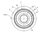
- FIG. FIG. 4 is an explanatory diagram showing a meshing state of an external gear with an internal gear of a strain wave gearing; It is an explanatory view showing a semi-longitudinal section of the strain wave gearing, showing another example of attachment of the detection mechanism. It is an explanatory view showing an example of an actuator provided with a strain wave gearing.
- FIG. 5 is an explanatory diagram showing another example of a strain wave gearing to which the present invention is applied;
- FIG. 4 is an explanatory diagram showing an optical detection mechanism;
- FIG. 4 is an explanatory diagram showing a magnetic detection mechanism
- 1 is an explanatory diagram showing an example of a top hat type wave gear device to which the present invention is applied
- FIG. 1 is an explanatory diagram showing an example of a pancake-type strain wave gearing to which the present invention is applied;
- a cup-shaped strain wave gearing 1 to which the present invention is applied comprises a rigid internal gear 2 and a cup-shaped flexible external gear coaxially arranged therein.
- a toothed gear 3 , a wave generator 4 coaxially mounted inside the gear 3 , a device housing 5 , and a detection mechanism 6 incorporated inside the device housing 5 are provided.
- the detection mechanism 6 is a mechanism for detecting a minute displacement in the direction of the axis 1a of the wave generator 4 due to the thrust force generated between the external gear 3 and the wave generator 4. As shown in FIG.
- the detection result of the detection mechanism 6 is supplied to the drive control device 20 by wire or wirelessly.
- the drive control device 20 is mainly composed of a computer, and includes an operating state determination section 20a and an operation control section 20b. Based on the detection result of the detection mechanism 6, the operating state determination unit 20a provides information such as the presence or absence of thrust force acting on the wave generator 4, the direction of the thrust force, the magnitude of the thrust force, and the temporal change of the thrust force. Calculate Further, the operating state determination unit 20a determines the operating state of the strain wave gearing 1 based on the calculated information regarding the thrust force. The operation control unit 20b controls the operating state of the strain wave gearing 1 based on the determination result of the operating state.
- the device housing 5 includes a cylindrical input-side housing 51 and a cylindrical output-side housing 52 coaxially fastened and fixed to one end of the input-side housing 51 .
- the input-side housing 51 includes a large-diameter mounting flange 51a, a cylindrical housing portion 51b coaxially protruding from the end surface of the mounting flange 51a, and an end plate portion closing the end of the cylindrical housing portion 51b. 51c.
- an output shaft 8 is rotatably supported at the output-side end of the output-side housing 52 via a cross roller bearing 7 .
- the internal gear 2 is a fixed-side member, and the internal gear 2 of this example is integrally formed on the inner peripheral surface of the output-side housing 52 of the device housing 5 .
- the wave generator 4 is a member on the input side to which high-speed rotation is input, and is coaxially connected to the motor shaft 9 as indicated by the imaginary line.
- the external gear 3 is a member on the output side that outputs reduced rotation, and a disk-shaped output shaft 8 is coaxially connected to the external gear 3 .
- the external gear 3 comprises a radially flexible cylindrical body 31 , external teeth 32 formed on the outer peripheral surface of the cylindrical body 31 on the side of the open end of the cylindrical body 31 , and the open end of the cylindrical body 31 .
- a diaphragm 33 extends radially inwardly from the opposite end, and an annular rigid boss 34 connected to the inner peripheral edge of the diaphragm 33 .
- the external gear 3 is coaxially mounted inside the internal gear 2, and the external teeth 32 face the internal teeth 21 of the internal gear 2 from the inside in the radial direction.
- the boss 34 is sandwiched between the annular pressing member 11 and the output shaft 8, and these three members are fastened and fixed by a plurality of fastening bolts.
- the wave generator 4 comprises a rigid wave plug 41 with an elliptical outer peripheral surface and a wave bearing 42 attached to the elliptical outer peripheral surface.
- the wave bearing 42 is mounted between the elliptical outer peripheral surface of the wave plug 41 and the inner peripheral surface of the cylindrical body portion 31 of the external gear 3 to allow the wave plug 41 and the external gear 3 to rotate relative to each other. keeping. Further, the portion of the cylindrical body 31 of the external gear 3 where the external teeth 32 are formed is elliptically flexed by the wave bearing 42 attached to the wave plug 41 and elliptically flexed. .
- the external teeth 32 positioned at both end portions of the elliptical major axis Lmax mesh with the internal teeth 21 of the internal gear 2 .
- a cylindrical hub 43 is coaxially formed integrally with one plug end face 41a (input-side plug end face) of the wave plug 41 in the direction of the axis 1a.
- the tip of the hub 43 is rotatably supported by the inner peripheral edge of the center opening of the end plate portion 51c of the input housing 51 via a bearing 12.
- the hub 43 is attached to the input side housing 51 via a bearing 12 so as not to move relative to the input side housing 51 in the direction of the axis 1a.
- a motor shaft 9 indicated by an imaginary line is inserted into the center shaft hole of the hub 43 from its tip opening and is coaxially connected to the hub 43 .
- the hub 43 and the motor shaft 9 are connected via, for example, a spline joint 13, and the hub 43 and the motor shaft 9 rotate integrally, but are relatively slidable in the direction of the axis 1a. .
- substantially no axial force is transmitted between the motor shaft 9 and the wave generator 4, and only rotational force is transmitted between them.
- the detection mechanism 6 detects a minute axial displacement generated in the hub 43 of the wave plug 41 in the wave generator 4 .
- the detection mechanism 6 is incorporated between the hub 43 and the input side housing 51 of the device housing 5 surrounding it.
- the detection mechanism 6 of this example is a laser length measuring device type detection mechanism, and includes a detection unit 61 that emits and receives laser light, and a reflection section 62 that has a reflection surface 62a that reflects the laser light. .
- the detection unit 61 includes a laser light source 63 that emits laser light toward the reflecting surface 62a, and a light receiving section 64 that receives the laser light reflected by the reflecting surface 62a.
- a laser length-measuring device accurately measures a distance using a triangulation method, a phase-difference ranging method, or the like.
- the detection unit 61 is attached to the end plate portion 51c of the input-side housing 51.
- the reflecting portion 62 is attached to the plug end face 41a of the wave plug 41 facing the end plate portion 51c in the direction of the axis 1a.
- a reflecting surface 62 a of the reflecting portion 62 has a ring shape of a constant width that coaxially surrounds the hub 43 .
- the reflective surface 62a is a surface orthogonal to the axis 1a, and the detection unit 61 faces the reflective surface 62a from the direction along the axis 1a.
- a pair of detection units 61 are arranged at symmetrical angular positions 180 degrees apart in the circumferential direction on the reflecting surface 62a with the axis 1a as the center. By arranging three or more detection units 61, detection accuracy can be improved.
- the motor shaft 9 and the hub 43 of the wave generator 4 are connected via a spline joint 13, and rotate integrally while being relatively movable in the direction of the axis 1a. Only the rotational force is transmitted from the external motor shaft 9 to the wave generator 4, and the axial force is not transmitted. A thrust force generated between the external gear 3 and the wave generator 4 acts on the wave plug 41 integrally formed with the hub 43 .
- the hub 43 of the wave plug 41 of the wave generator 4 is supported by the input side housing 51 of the fixed device housing 5 via the bearing 12 so as not to move in the direction of the axis 1a.
- the hub 43 of the wave plug 41 is slightly displaced in the direction of the axis 1a.
- the position of the reflection surface 62a on the wave plug 41 side is slightly displaced relative to the light receiving portion 64 of the detection unit 61 in the direction of the axis 1a.
- a minute displacement amount is measured by the detection mechanism 6 .
- the detection result (measured minute displacement amount) of the detection mechanism 6 is supplied to the drive control device 20 by wire or wirelessly.
- the operating state determination unit 20a of the drive control device 20 determines or calculates the presence or absence of thrust force generation, the direction of the thrust force, the magnitude of the thrust force, the temporal change of the thrust force, and the like. do.
- the operation control unit 20b controls the operation of the strain wave gearing 1 based on the detection result by the detection mechanism 6 or the determination result by the operation state determination unit 20a.
- the detection accuracy can be improved by correcting the temperature of the detection mechanism 6.
- the temperature sensor 10 is arranged near the plug end surface 41a of the wave plug 41 or the outer peripheral surface of the hub 43, as indicated by the imaginary line in FIG. 1A.
- the output of the temperature sensor 10 is taken into the drive control device 20, and the detection result is corrected for temperature.
- temperature correction can be performed by arranging a temperature sensor.
- FIG. 2 is an explanatory view including a half longitudinal section of the strain wave gearing 1, and shows another mounting example of the detection mechanism 6 incorporated in the strain wave gearing 1.
- the detection unit 61 of the detection mechanism 6 shown in FIG. 2 is attached to the input side housing 51 so as to be tilted by an angle of less than 90 degrees with respect to the axis 1a.
- the reflecting surface 62a of the reflecting portion 62 arranged on the plug end face 41a of the wave plug 41 is also inclined with respect to the axis 1a. In this way, the detection mechanism 6 can also be arranged to be inclined with respect to the axis 1a.
- FIG. 3 is an explanatory diagram showing an example of an actuator (rotary actuator) using the strain wave gearing 1 of this example.
- the actuator 100 includes a motor 110, a wave gear device 1 that decelerates and outputs the motor output rotation, a rotation detection mechanism 120 and a brake mechanism 130 incorporated in the motor 110, and a controller 140.
- the control device 140 has the functions of the operating state determination unit 20a and the operation control unit 20b described above.
- the control device 140 obtains the thrust force from the minute displacement of the wave generator 4 that is detected. By controlling the drive of the motor 110 and the brake mechanism 130 based on the thrust force and controlling the input rotation to the wave gear device 1 (wave generator 4), the operation of the wave gear device 1 can be controlled. .
- the operation state of the strain wave gearing 1 is determined and the operation control is performed as follows. (1) By detecting the direction of the thrust force, it is determined whether the strain wave gearing 1 is in the deceleration operation state or the acceleration operation state. During speed-up operation, the friction torque generated by the brake mechanism 130 or the like can reduce the efficiency and reduce the holding torque of the motor 110 . (2) The next state can be determined based on the presence or absence of thrust force generation. If the wave generator 4 and the motor shaft 9 connected thereto are completely locked, no thrust force is generated. Therefore, it is possible to determine whether the locking force of the target shaft is excessive or insufficient when the operation is stopped.
- the lubricating state is the operating posture of the strain wave gearing 1, the operating state (unidirectional constant continuous operation, high load low speed operation, short cycle and large acceleration rate in forward and reverse, long stop time, type and state of lubricant). Varies depending on Life prediction and diagnosis can be performed based on the lubrication state. If it is found that the lubricating state has deteriorated, the lubricating state can be restored to a good state. For example, it is possible to reduce the load torque, reduce the acceleration rate, and set an appropriate rotation speed and operating time.
- FIG. 4A is an explanatory diagram including a longitudinal section of a strain wave gearing in which different types of detection mechanisms are incorporated
- FIG. 4B is an explanatory diagram showing the portion of the detection mechanism. Since the strain wave gearing 1A has the same configuration as the strain wave gearing 1, the same reference numerals are used for the corresponding portions, and the description of those portions is omitted.
- the detection mechanism 160 incorporated in the strain wave gearing 1A is an optical detection mechanism, and includes an optically detectable detection pattern 161 arranged on the outer peripheral surface 43a of the hub 43 of the wave plug 41, and a detection pattern 161 on the device housing 5. and an optical detection unit 162 attached to the input housing 51 .
- the detection pattern 161 arranged on the outer peripheral surface 43a of the hub 43 is a pattern that can expand and contract following the displacement of the outer peripheral portion of the hub in the direction of the axis 1a.
- the detection pattern 161 of this example is light reflecting portions 161a and non-reflecting portions 161b of constant width alternately formed at equal intervals along the direction of the axis 1a. formed around the circumference.
- the detection unit 162 includes a light emitting section 163 , a fixed slit plate 164 and a light receiving section 165 .
- the light-emitting portion 163 emits detection light toward the detection pattern 161 through a fixed slit 164 a that is a light transmitting portion formed in the fixed slit plate 164 .
- the fixed slits 164a are also slits of constant width arranged at equal intervals along the direction of the axis 1a.
- the light receiving section 165 receives the reflected light of the detection light reflected by the detection pattern 161 through the fixed slit 164 a of the fixed slit plate 164 .
- the detection pattern 161 expands and contracts in the direction of the axis 1a.
- the amount of reflected light received by the light receiving portion 165 changes according to the minute displacement of the hub 43 .
- the detection units 162 can be arranged at a plurality of positions in the circumferential direction of the outer peripheral surface 43 a of the hub 43 .
- a pair of detection units 162 are arranged at symmetrical angular positions separated by 180 degrees about the axis 1a. This can improve detection accuracy.
- the detection unit 162 one having a ring-shaped light-emitting portion and a ring-shaped light-receiving portion coaxially surrounding the detection pattern 161 can be used.
- a plurality of detection units 162 of three or more can also be arranged.
- the optically detectable detection pattern 161 can be directly formed on the outer peripheral surface 43a of the hub 43 by surface treatment, printing, or the like.
- a flexible film or the like on which the detection pattern 161 is formed or printed may be attached to the outer peripheral surface 43 a of the hub 43 .
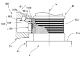
- FIG. 4C is an explanatory diagram showing an example of a magnetic detection mechanism.
- the magnetic detection mechanism 260 incorporated in the strain wave gearing 1A is a magnetically detectable detection mechanism arranged on the outer peripheral surface 43a of the hub 43 of the wave plug 41. It has a pattern 261 and a magnetic detection unit 262 attached to the input side housing 51 of the device housing 5 .
- the detection pattern 261 arranged on the outer peripheral surface 43a of the hub 43 is a pattern that can expand and contract following the displacement of the outer peripheral portion of the hub in the direction of the axis 1a.
- the detection pattern 161 of this example is magnetic portions 261a and non-magnetic portions 261b of a constant width alternately formed at equal intervals along the direction of the axis 1a. formed.
- the detection pattern 261 can be obtained by arranging magnetic ring zones formed by applying metallic magnetic powder or the like with a constant width on the outer peripheral surface 43a of the hub 43 at equal intervals in the direction of the axis 1a.
- a magnetic zone may be formed directly by surface treatment of the outer peripheral surface 43a of the hub 43.
- the outer peripheral surface 43a of the hub 43 made of austenitic stainless steel is subjected to shot peening treatment for transforming non-magnetic and plastically deformable retained austenite into martensite, and the treated surface is finished by polishing to reduce the axial line.
- Magnetic portions are formed at regular intervals in the direction.
- a flexible film or the like printed with a detection pattern 261 made of a magnetic medium may be attached to the outer peripheral surface 43 a of the hub 43 .
- the detection unit 262 includes a magnet 263 opposed to the detection pattern 261 so that the magnetic field strength changes as the detection pattern 261 expands and contracts in the direction of the axis 1a, and a magnetic detection element 264 such as an MR element for detecting changes in the magnetic field strength. It has The magnet 263 has N poles and S poles of constant width alternately formed at regular intervals along the direction of the axis 1a.
- the magnetic detection units 262 can also be arranged at a plurality of positions in the circumferential direction of the outer peripheral surface 43a of the hub 43. For example, a pair of detection units 262 are arranged at symmetrical angular positions separated by 180 degrees about the axis 1a. This can improve detection accuracy. As the detection unit 262, one having a ring-shaped magnet coaxially surrounding the detection pattern 261 and a ring-shaped magnetic detection element can also be used. More than two detection units can also be arranged.
- strain wave gearing (Another example of strain wave gearing)
- the above example is a case where the present invention is applied to a cup-type strain wave gearing.
- the present invention can also be applied to a top hat type strain wave gearing and a pancake type strain wave gearing.
- FIG. 5 is an explanatory diagram showing a top hat type wave gear device 1B in which the detection mechanism 6 is incorporated.
- the top hat type wave gear device 1B includes a rigid internal gear 2B, a top hat-shaped external gear 3B, a wave generator 4B, and an input side housing 51B (device housing).
- the silk hat-shaped external gear 3B includes a cylindrical body 31B, external teeth 32B formed on the outer peripheral surface of the cylindrical body 31B, a diaphragm 33B extending radially outward from one end of the cylindrical body 31B, and the diaphragm 33B.
- a rigid boss 34B having an annular shape formed on the outer peripheral edge is provided.
- the boss 34B is coaxially fixed to the disk-shaped output shaft 8B and the outer ring of the cross roller bearing 7B.
- a detection mechanism 6 (160, 260) is incorporated between the hub 43B of the wave plug 41B of the wave generator 4B and the input side housing 51B surrounding it.
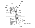
- FIG. 6 is an explanatory diagram showing a pancake-type wave gear device 1C in which a detection mechanism is incorporated.
- a strain wave gearing device 1C of pancake type includes a rigid internal gear 2C, a flexible external gear 3C coaxially arranged inside the internal gear 2C, and coaxially arranged inside the external gear 3C.
- the strain wave gearing 1C also includes a rigid drive-side internal gear 2D arranged coaxially with the internal gear 2C and aligned in the direction of the axis.
- a disk-shaped output shaft 8C is coaxially fixed to the driving side internal gear 2D.
- the externally toothed gear 3C which is deflected non-circularly by the wave generator 4C, also partially meshes with the driving side internally toothed gear 2D.
- the external gear 3C has a radially flexible cylindrical body, and external teeth are formed on its outer peripheral surface.
- the internal gear 2C has a different number of teeth from the external gear 3C, and the driving side internal gear 2D has the same number of teeth as the external gear 3C so that it rotates together with the external gear 3C.
- a detection mechanism 6 (160, 260) is incorporated between the hub 43C of the wave plug 41C of the wave generator 4C and the input side housing 51C surrounding it.
Abstract
Description
剛性の内歯歯車と、
前記内歯歯車の内側に配置された可撓性の外歯歯車と、
前記外歯歯車の内側に配置され、前記外歯歯車を非円形に撓めて前記内歯歯車に部分的にかみ合わせている波動発生器と、
前記波動発生器を回転自在の状態で支持している装置ハウジングと、
前記波動発生器と前記外歯歯車との間に発生するスラスト力を検出するために、前記スラスト力により前記波動発生器に生じる軸線の方向の変位を検出する検出機構と、
を備えており、
前記波動発生器は、前記軸線の方向に相対移動可能な状態で一体回転するように、外部の回転軸に連結されるハブを備えており、
前記装置ハウジングは前記ハブを取り囲む筒状ハウジング部分を備えており、
前記検出機構は、前記ハブと前記筒状ハウジング部分との間に配置され、前記ハブに生じる前記軸線の方向の変位を検出することを特徴としている。
図1Aおよび図1Bを参照して説明すると、本発明を適用したカップ型の波動歯車装置1は、剛性の内歯歯車2と、この内側に同軸に配置したカップ形状をした可撓性の外歯歯車3と、この内側に同軸に装着した波動発生器4と、装置ハウジング5と、装置ハウジング5の内側に組み込まれた検出機構6とを備えている。検出機構6は、外歯歯車3と波動発生器4との間に発生するスラスト力によって波動発生器4に生じる軸線1aの方向の微小変位を検出する機構である。検出機構6の検出結果は、有線あるいは無線により、駆動制御装置20に供給される。
検出機構6は、波動発生器4におけるウエーブプラグ41のハブ43に発生する軸線方向の微小軸変位を検出する。検出機構6は、ハブ43と、これを取り囲む装置ハウジング5の入力側ハウジング51との間に組み込まれている。
この構成の波動歯車装置1において、モータ軸9によって波動発生器4が高速回転すると、外歯歯車3の内歯歯車2に対するかみ合い位置が、内歯歯車2の円周方向に移動する。外歯歯車3は内歯歯車2よりも歯数が2n枚少ない(n:正の整数)。本例では内歯歯車2が固定されているので、波動発生器4の回転に伴って外歯歯車3が減速回転する。外歯歯車3の減速回転が、そのボス34に連結されている出力軸8から不図示の負荷側に出力される。
図2は波動歯車装置1の半縦断面を含む説明図であり、波動歯車装置1に組み込まれた検出機構6の別の取付例を示してある。図2に示す検出機構6の検出ユニット61は、軸線1aに対して90度未満の角度だけ傾斜した向きとなるように、入力側ハウジング51に取り付けられている。検出ユニット61から射出されるレーザー光の向きに対応させて、ウエーブプラグ41のプラグ端面41aに配置した反射部62の反射面62aも、軸線1aに対して傾斜させてある。このように、軸線1aに対して検出機構6を傾斜して配置することもできる。
図3は、本例の波動歯車装置1を用いたアクチュエータ(回転アクチュエータ)の一例を示す説明図である。この図に示すように、アクチュエータ100は、モータ110と、モータ出力回転を減速して出力する波動歯車装置1と、モータ110に組み込まれた回転検出機構120およびブレーキ機構130と、制御装置140とから構成される。制御装置140は、先に述べた運転状態判別部20aおよび運転制御部20bの機能を備えている。
(1)スラスト力の方向検出によって、波動歯車装置1が減速運転か増速運転状態にあるのかを判別する。増速運転時には、ブレーキ機構130などによる摩擦トルクで、効率を低下させ、モータ110の保持トルクを低減させることができる。
(2)スラスト力の発生の有無に基づき次の状態を判別できる。波動発生器4及びこれに連結されるモータ軸9が完全にロック状態であればスラスト力は発生しない。よって、動作停止時の対象軸のロック力の過不足を判別できる。
多軸ロボットなど他の軸が動作中の場合、対象軸の波動歯車装置1によるロックが不足の場合では、増速運転となり、スラスト力が発生する。よって、ブレーキ機構130等を利用して、動作停止時の対象軸のロック力を大きくすることで、ロック力の不足に対応できる。
(3)スラスト力の大きさ、変動には、負荷トルクと、外歯歯車3の内周面と波動発生器4の外輪外周面の間の潤滑状態が大きく影響する。スラスト力の大きさ、変動に基づき、外歯歯車3の内周面と波動発生器4のウエーブベアリングの外輪外周面との間の潤滑状態の状態を知ることができる。
潤滑状態は、波動歯車装置1の運転姿勢、運転状態(一方向一定連続運転、高負荷低速運転、正逆時の短サイクルと大きな加速レ-ト、長期停止時間、潤滑剤の種類・状態)によって変動する。潤滑状態に基づき、寿命予知、診断を行うことができる。
潤滑状態が悪化していることが分かれば、潤滑状態を良好な状態に復帰させることができる。例えば、負荷トルクの低下、加速レ-トの低減、適正な回転数と運転時間の設定等を行うことができる。
(光学式の検出機構の例)
図4Aは、異なる形式の検出機構が組み込まれた波動歯車装置の縦断面を含む説明図であり、図4Bはその検出機構の部分を示す説明図である。波動歯車装置1Aは波動歯車装置1と同一構成であるので、対応する部位には同一の符号を使用し、それらの部位の説明を省略する。
次に、検出機構として、磁気式の検出機構を用いることができる。図4Cは、磁気式の検出機構の一例を示す説明図である。この図を参照して説明すると、波動歯車装置1A(図4A参照)に組み込まれる磁気式の検出機構260は、ウエーブプラグ41のハブ43の外周面43aに配置された磁気的に検出可能な検出模様261と、装置ハウジング5の入力側ハウジング51に取り付けた磁気式の検出ユニット262とを備えている。
上記の例は、本発明をカップ型の波動歯車装置に適用した場合のものである。本発明は、シルクハット型の波動歯車装置、パンケーキ型の波動歯車装置に対しても適用可能である。
Claims (17)
- 剛性の内歯歯車と、
前記内歯歯車の内側に配置された可撓性の外歯歯車と、
前記外歯歯車の内側に配置され、前記外歯歯車を非円形に撓めて前記内歯歯車に部分的にかみ合わせている波動発生器と、
前記波動発生器を回転自在の状態で支持している装置ハウジングと、
前記波動発生器と前記外歯歯車との間に発生するスラスト力を算出するために、前記スラスト力により前記波動発生器に生じる軸線の方向の変位を検出する検出機構と、
を備えており、
前記波動発生器は、前記軸線の方向に相対移動可能な状態で一体回転するように、外部の回転軸に連結される円筒状のハブを備えており、
前記装置ハウジングは前記ハブを取り囲む筒状ハウジング部分を備えており、
前記検出機構は、前記ハブと前記筒状ハウジング部分との間に配置され、前記ハブに生じる前記軸線の方向の変位を検出する波動歯車装置。 - 請求項1において、
前記波動発生器は非円形外周面を備えた剛性のウエーブプラグを備え、
前記ハブは、前記ウエーブプラグにおける前記軸線の方向の一方のプラグ端面に、一体形成され、あるいは、固定されており、
前記検出機構は、レーザー光源、このレーザー光源からのレーザー光を反射する反射部、および前記反射部で反射した前記レーザー光を受光する受光部を備えており、
前記レーザー光源および前記受光部を備えた検出ユニットは、前記装置ハウジングに取り付けられ、
前記反射部は、前記プラグ端面に設けられている波動歯車装置。 - 請求項2において、
前記反射部は、前記プラグ端面において前記軸線を中心とするリング形状の反射面を備えており、
前記軸線を中心として180度離れた対称の角度位置に配置した少なくとも一対の前記検出ユニットを備えている波動歯車装置。 - 請求項1において、
前記検出機構は、
前記ハブの外周面に配置され、このハブの変位に追従して前記軸線の方向に伸縮可能な検出模様と、
前記装置ハウジングに取り付けられ、前記検出模様の伸縮を光学的あるいは磁気的に検出する検出ユニットと、
を備えている波動歯車装置。 - 請求項4において、
前記検出模様は、前記軸線の方向に沿って、等間隔で交互に形成された光の反射部および非反射部であり、
前記検出ユニットは、前記軸線の方向に沿って等間隔に形成した光通過部が形成された固定スリット板、前記光通過部を介して前記検出模様に検出光を照射する発光部、および前記反射部で反射された前記検出光を前記光通過部を介して受光する受光部を備えている光学式の検出ユニットである波動歯車装置。 - 請求項5において、
前記軸線を中心として180度離れた対称の角度位置に配置した少なくとも一対の前記検出ユニットを備えている波動歯車装置。 - 請求項6において、
前記検出模様は、前記ハブの全周に亘って形成されており、
前記検出ユニットは、前記検出模様を同軸状に取り囲むリング状の発光部およびリング状の受光部を備えている波動歯車装置。 - 請求項5において、
前記検出模様は、
前記ハブの外周面に直接形成されているか、または、
前記ハブの外周面に貼り付けたフィルムに形成されている波動歯車装置。 - 請求項4において、
前記検出模様は、前記軸線の方向に沿って等間隔で交互に形成した磁性部および非磁性部であり、
前記検出ユニットは、
前記検出模様の前記軸線の方向の伸縮に伴って磁場強度が変化するように前記検出模様に対峙させた磁石および前記磁場強度の変化を検出する磁気検出素子を備えた磁気式の検出ユニットである波動歯車装置。 - 請求項9において、
前記軸線を中心として180度離れた対称の角度位置に配置した少なくとも一対の前記検出ユニットを備えている波動歯車装置。 - 請求項9において、
前記検出模様は、前記ハブの全周に亘って形成されており、
前記検出ユニットは、前記検出模様を同軸状に取り囲むリング状の磁石およびリング状の磁気検出素子を備えている波動歯車装置。 - 請求項9において、
前記検出模様は、
前記ハブの外周面に直接形成されているか、または、
前記ハブの外周面に貼り付けたフィルムに形成されている波動歯車装置。 - 請求項1において、
前記検出機構によって検出された前記変位の温度補正を行うための温度センサが、前記ハブの近傍に配置されている波動歯車装置。 - 請求項1において、更に、
前記検出機構による検出結果に基づき、前記スラスト力の発生の有無、前記スラスト力の方向、前記スラスト力の大きさ、および、前記スラスト力の時間的変化のうちの少なくとも一つを算出する算出部と、
前記算出部の算出結果に基づき、前記波動歯車装置の運転状態を判別する運転状態判別部と、
を備えている波動歯車装置。 - 請求項14において、更に、
前記検出機構による検出結果、または、前記運転状態判別部による判別結果に基づき、前記波動歯車装置の運転制御を行う運転制御部を備えている波動歯車装置。 - 請求項15に記載の波動歯車装置と、
前記波動発生器の前記ハブにモータ軸が連結されたモータと、
を備えており、
前記運転制御部は、前記モータから前記波動歯車装置への入力回転を制御することで、前記波動歯車装置の前記運転制御を行うアクチュエータ。 - 請求項16において、更に、
前記波動歯車装置への入力回転を制御するブレーキ機構を備えており、
前記運転制御部は、前記ブレーキ機構を制御することで、前記波動歯車装置の前記運転制御を行うアクチュエータ。
Priority Applications (5)
| Application Number | Priority Date | Filing Date | Title |
|---|---|---|---|
| KR1020247002759A KR20240024257A (ko) | 2021-09-21 | 2021-09-21 | 파동기어장치 및 액추에이터 |
| PCT/JP2021/034641 WO2023047469A1 (ja) | 2021-09-21 | 2021-09-21 | 波動歯車装置およびアクチュエータ |
| CN202180101337.XA CN117916493A (zh) | 2021-09-21 | 2021-09-21 | 波动齿轮装置以及致动器 |
| JP2023549202A JPWO2023047469A1 (ja) | 2021-09-21 | 2021-09-21 | |
| TW111125920A TW202323694A (zh) | 2021-09-21 | 2022-07-11 | 諧波齒輪裝置及致動器 |
Applications Claiming Priority (1)
| Application Number | Priority Date | Filing Date | Title |
|---|---|---|---|
| PCT/JP2021/034641 WO2023047469A1 (ja) | 2021-09-21 | 2021-09-21 | 波動歯車装置およびアクチュエータ |
Publications (1)
| Publication Number | Publication Date |
|---|---|
| WO2023047469A1 true WO2023047469A1 (ja) | 2023-03-30 |
Family
ID=85720270
Family Applications (1)
| Application Number | Title | Priority Date | Filing Date |
|---|---|---|---|
| PCT/JP2021/034641 WO2023047469A1 (ja) | 2021-09-21 | 2021-09-21 | 波動歯車装置およびアクチュエータ |
Country Status (5)
| Country | Link |
|---|---|
| JP (1) | JPWO2023047469A1 (ja) |
| KR (1) | KR20240024257A (ja) |
| CN (1) | CN117916493A (ja) |
| TW (1) | TW202323694A (ja) |
| WO (1) | WO2023047469A1 (ja) |
Citations (9)
| Publication number | Priority date | Publication date | Assignee | Title |
|---|---|---|---|---|
| JPH0415518A (ja) * | 1990-05-10 | 1992-01-20 | Matsushita Electric Ind Co Ltd | 移動検出装置 |
| WO2002076813A1 (fr) * | 2001-03-27 | 2002-10-03 | Sunstar Giken Kabushiki Kaisha | Capteur de vitesse de rotation et bicyclette servo-assistee equipee d'un capteur de vitesse de rotation |
| JP2007231996A (ja) | 2006-02-28 | 2007-09-13 | Harmonic Drive Syst Ind Co Ltd | 波動歯車装置の入力側保持トルクの低減方法および回転アクチュエータ |
| JP2011236629A (ja) * | 2010-05-10 | 2011-11-24 | Sanwa Kizai Co Ltd | 推進工法における掘削ヘッド回転速度検出装置 |
| JP2011240488A (ja) * | 2011-09-07 | 2011-12-01 | Panasonic Electric Works Power Tools Co Ltd | 回転式工具 |
| JP2017083311A (ja) * | 2015-10-28 | 2017-05-18 | 株式会社リコー | マーク検出装置、ベルト制御装置、画像形成装置、マーク検出方法およびプログラム |
| WO2018159032A1 (ja) * | 2017-02-28 | 2018-09-07 | ソニー株式会社 | アクチュエータ |
| JP2019105314A (ja) | 2017-12-13 | 2019-06-27 | 住友重機械工業株式会社 | 撓み噛合い式歯車装置 |
| JP2020200845A (ja) * | 2019-06-06 | 2020-12-17 | 株式会社Soken | 噛み合いクラッチ |
-
2021
- 2021-09-21 CN CN202180101337.XA patent/CN117916493A/zh active Pending
- 2021-09-21 JP JP2023549202A patent/JPWO2023047469A1/ja active Pending
- 2021-09-21 KR KR1020247002759A patent/KR20240024257A/ko unknown
- 2021-09-21 WO PCT/JP2021/034641 patent/WO2023047469A1/ja active Application Filing
-
2022
- 2022-07-11 TW TW111125920A patent/TW202323694A/zh unknown
Patent Citations (9)
| Publication number | Priority date | Publication date | Assignee | Title |
|---|---|---|---|---|
| JPH0415518A (ja) * | 1990-05-10 | 1992-01-20 | Matsushita Electric Ind Co Ltd | 移動検出装置 |
| WO2002076813A1 (fr) * | 2001-03-27 | 2002-10-03 | Sunstar Giken Kabushiki Kaisha | Capteur de vitesse de rotation et bicyclette servo-assistee equipee d'un capteur de vitesse de rotation |
| JP2007231996A (ja) | 2006-02-28 | 2007-09-13 | Harmonic Drive Syst Ind Co Ltd | 波動歯車装置の入力側保持トルクの低減方法および回転アクチュエータ |
| JP2011236629A (ja) * | 2010-05-10 | 2011-11-24 | Sanwa Kizai Co Ltd | 推進工法における掘削ヘッド回転速度検出装置 |
| JP2011240488A (ja) * | 2011-09-07 | 2011-12-01 | Panasonic Electric Works Power Tools Co Ltd | 回転式工具 |
| JP2017083311A (ja) * | 2015-10-28 | 2017-05-18 | 株式会社リコー | マーク検出装置、ベルト制御装置、画像形成装置、マーク検出方法およびプログラム |
| WO2018159032A1 (ja) * | 2017-02-28 | 2018-09-07 | ソニー株式会社 | アクチュエータ |
| JP2019105314A (ja) | 2017-12-13 | 2019-06-27 | 住友重機械工業株式会社 | 撓み噛合い式歯車装置 |
| JP2020200845A (ja) * | 2019-06-06 | 2020-12-17 | 株式会社Soken | 噛み合いクラッチ |
Also Published As
| Publication number | Publication date |
|---|---|
| KR20240024257A (ko) | 2024-02-23 |
| TW202323694A (zh) | 2023-06-16 |
| JPWO2023047469A1 (ja) | 2023-03-30 |
| CN117916493A (zh) | 2024-04-19 |
Similar Documents
| Publication | Publication Date | Title |
|---|---|---|
| TWI655833B (zh) | 具電動機的減速機 | |
| KR100854517B1 (ko) | 파동 기어 장치 | |
| JPS60256643A (ja) | 減速装置 | |
| JP4787753B2 (ja) | 減速機付き駆動装置 | |
| EP2492057B1 (en) | Robot, robot system, and rotating electrical machine | |
| KR101725918B1 (ko) | 검출기구를 구비한 선회 액추에이터 및 관절 유닛 | |
| US5672135A (en) | Controller for planetary differential type reduction gear device | |
| JP4885292B2 (ja) | 駆動装置 | |
| JP6601836B2 (ja) | 電動機付き減速機 | |
| WO2021095362A1 (ja) | 駆動装置 | |
| CN113597523A (zh) | 平行连杆机构和连杆致动装置 | |
| JP2014083613A (ja) | ロボット | |
| WO2023047469A1 (ja) | 波動歯車装置およびアクチュエータ | |
| JP5865957B2 (ja) | トルクを検出するための電動自転車用の伝動装置、及び電動自転車のための、トルクを検出する方法 | |
| CN110549373B (zh) | 一种驱动机构 | |
| WO2023026488A1 (ja) | 波動歯車装置およびアクチュエータ | |
| JP2014238117A (ja) | 減速機内蔵アクチュエータ及びこれを備える多関節ロボット | |
| US20130211422A1 (en) | Compact rotary actuator with internal planetary | |
| JPH1114656A (ja) | 角加速度センサ内蔵アクチュエータ | |
| JP4185746B2 (ja) | 相対回転状態検知装置 | |
| JP2638893B2 (ja) | 油圧ロータリアクチュエータ | |
| JP3399586B2 (ja) | 角度および角加速度の一体型検出装置 | |
| TW201535955A (zh) | 進行振動發電的波動齒輪裝置 | |
| KR100798087B1 (ko) | 감속기 장착 구동 장치 | |
| JP2019056458A (ja) | 無段変速機 |
Legal Events
| Date | Code | Title | Description |
|---|---|---|---|
| 121 | Ep: the epo has been informed by wipo that ep was designated in this application |
Ref document number: 21958346 Country of ref document: EP Kind code of ref document: A1 |
|
| WWE | Wipo information: entry into national phase |
Ref document number: 2023549202 Country of ref document: JP |
|
| ENP | Entry into the national phase |
Ref document number: 20247002759 Country of ref document: KR Kind code of ref document: A |
|
| WWE | Wipo information: entry into national phase |
Ref document number: 1020247002759 Country of ref document: KR |
|
| WWE | Wipo information: entry into national phase |
Ref document number: 2021958346 Country of ref document: EP |
|
| ENP | Entry into the national phase |
Ref document number: 2021958346 Country of ref document: EP Effective date: 20240422 |