WO2023042866A1 - ベースプレート、スピンドルモータ、ディスク駆動装置及びベースプレートの製造方法 - Google Patents
ベースプレート、スピンドルモータ、ディスク駆動装置及びベースプレートの製造方法 Download PDFInfo
- Publication number
- WO2023042866A1 WO2023042866A1 PCT/JP2022/034466 JP2022034466W WO2023042866A1 WO 2023042866 A1 WO2023042866 A1 WO 2023042866A1 JP 2022034466 W JP2022034466 W JP 2022034466W WO 2023042866 A1 WO2023042866 A1 WO 2023042866A1
- Authority
- WO
- WIPO (PCT)
- Prior art keywords
- base plate
- die
- bottom plate
- plate
- cast
- Prior art date
- Legal status (The legal status is an assumption and is not a legal conclusion. Google has not performed a legal analysis and makes no representation as to the accuracy of the status listed.)
- Ceased
Links
Images









Classifications
-
- G—PHYSICS
- G11—INFORMATION STORAGE
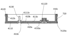
- G11B—INFORMATION STORAGE BASED ON RELATIVE MOVEMENT BETWEEN RECORD CARRIER AND TRANSDUCER
- G11B33/00—Constructional parts, details or accessories not provided for in the other groups of this subclass
- G11B33/02—Cabinets; Cases; Stands; Disposition of apparatus therein or thereon
- G11B33/022—Cases
-
- G—PHYSICS
- G11—INFORMATION STORAGE
- G11B—INFORMATION STORAGE BASED ON RELATIVE MOVEMENT BETWEEN RECORD CARRIER AND TRANSDUCER
- G11B19/00—Driving, starting, stopping record carriers not specifically of filamentary or web form, or of supports therefor; Control thereof; Control of operating function ; Driving both disc and head
- G11B19/20—Driving; Starting; Stopping; Control thereof
- G11B19/2009—Turntables, hubs and motors for disk drives; Mounting of motors in the drive
-
- G—PHYSICS
- G11—INFORMATION STORAGE
- G11B—INFORMATION STORAGE BASED ON RELATIVE MOVEMENT BETWEEN RECORD CARRIER AND TRANSDUCER
- G11B25/00—Apparatus characterised by the shape of record carrier employed but not specific to the method of recording or reproducing, e.g. dictating apparatus; Combinations of such apparatus
- G11B25/04—Apparatus characterised by the shape of record carrier employed but not specific to the method of recording or reproducing, e.g. dictating apparatus; Combinations of such apparatus using flat record carriers, e.g. disc, card
- G11B25/043—Apparatus characterised by the shape of record carrier employed but not specific to the method of recording or reproducing, e.g. dictating apparatus; Combinations of such apparatus using flat record carriers, e.g. disc, card using rotating discs
-
- G—PHYSICS
- G11—INFORMATION STORAGE
- G11B—INFORMATION STORAGE BASED ON RELATIVE MOVEMENT BETWEEN RECORD CARRIER AND TRANSDUCER
- G11B33/00—Constructional parts, details or accessories not provided for in the other groups of this subclass
- G11B33/02—Cabinets; Cases; Stands; Disposition of apparatus therein or thereon
-
- G—PHYSICS
- G11—INFORMATION STORAGE
- G11B—INFORMATION STORAGE BASED ON RELATIVE MOVEMENT BETWEEN RECORD CARRIER AND TRANSDUCER
- G11B33/00—Constructional parts, details or accessories not provided for in the other groups of this subclass
- G11B33/12—Disposition of constructional parts in the apparatus, e.g. of power supply, of modules
-
- G—PHYSICS
- G11—INFORMATION STORAGE
- G11B—INFORMATION STORAGE BASED ON RELATIVE MOVEMENT BETWEEN RECORD CARRIER AND TRANSDUCER
- G11B5/00—Recording by magnetisation or demagnetisation of a record carrier; Reproducing by magnetic means; Record carriers therefor
- G11B5/48—Disposition or mounting of heads or head supports relative to record carriers ; arrangements of heads, e.g. for scanning the record carrier to increase the relative speed
- G11B5/52—Disposition or mounting of heads or head supports relative to record carriers ; arrangements of heads, e.g. for scanning the record carrier to increase the relative speed with simultaneous movement of head and record carrier, e.g. rotation of head
- G11B5/53—Disposition or mounting of heads on rotating support
- G11B5/531—Disposition of more than one recording or reproducing head on support rotating cyclically around an axis
-
- H—ELECTRICITY
- H02—GENERATION; CONVERSION OR DISTRIBUTION OF ELECTRIC POWER
- H02K—DYNAMO-ELECTRIC MACHINES
- H02K15/00—Processes or apparatus specially adapted for manufacturing, assembling, maintaining or repairing of dynamo-electric machines
- H02K15/14—Casings; Enclosures; Supports
-
- H—ELECTRICITY
- H02—GENERATION; CONVERSION OR DISTRIBUTION OF ELECTRIC POWER
- H02K—DYNAMO-ELECTRIC MACHINES
- H02K5/00—Casings; Enclosures; Supports
- H02K5/04—Casings or enclosures characterised by the shape, form or construction thereof
- H02K5/06—Cast metal casings
-
- H—ELECTRICITY
- H02—GENERATION; CONVERSION OR DISTRIBUTION OF ELECTRIC POWER
- H02K—DYNAMO-ELECTRIC MACHINES
- H02K5/00—Casings; Enclosures; Supports
- H02K5/04—Casings or enclosures characterised by the shape, form or construction thereof
- H02K5/16—Means for supporting bearings, e.g. insulating supports or means for fitting bearings in the bearing-shields
- H02K5/167—Means for supporting bearings, e.g. insulating supports or means for fitting bearings in the bearing-shields using sliding-contact or spherical cap bearings
-
- Y—GENERAL TAGGING OF NEW TECHNOLOGICAL DEVELOPMENTS; GENERAL TAGGING OF CROSS-SECTIONAL TECHNOLOGIES SPANNING OVER SEVERAL SECTIONS OF THE IPC; TECHNICAL SUBJECTS COVERED BY FORMER USPC CROSS-REFERENCE ART COLLECTIONS [XRACs] AND DIGESTS
- Y10—TECHNICAL SUBJECTS COVERED BY FORMER USPC
- Y10T—TECHNICAL SUBJECTS COVERED BY FORMER US CLASSIFICATION
- Y10T29/00—Metal working
- Y10T29/49—Method of mechanical manufacture
- Y10T29/49002—Electrical device making
- Y10T29/4902—Electromagnet, transformer or inductor
- Y10T29/49021—Magnetic recording reproducing transducer [e.g., tape head, core, etc.]
- Y10T29/49025—Making disc drive
Definitions
- the present invention relates to a base plate, a spindle motor, a disk drive device, and a base plate manufacturing method.
- a base which is part of the housing of a conventional disk drive device, is formed by casting a die-cast member.
- a spindle motor is fixed on the base.
- a spindle motor rotates a plurality of disks around a rotation axis (see, for example, Patent Document 1).
- it has an actuator mounting portion (pivot post). The actuator mounting portion protrudes upward from the top surface of the bottom portion (see, for example, Patent Document 2).
- An object of the present invention is to provide a base plate and a method for manufacturing a base plate that can be made thinner while suppressing a decrease in strength, and a base plate and a method for manufacturing a base plate that can prevent gas leakage from a disk drive device.
- An exemplary base plate of the first invention for solving the problem is a base plate that forms part of a housing of a disk drive device, and is composed of a metal plate and a die-cast part.
- the metal plate has a plate-like bottom plate portion extending perpendicularly to the rotating shaft of the vertically extending disk.
- the die cast part covers at least part of the bottom plate part.
- the metal forming the bottom plate portion has higher rigidity than the metal forming the die cast portion.
- An exemplary base plate of a second invention for solving the problem is a base plate that forms part of a housing of a disk drive device, and includes a die cast part and a pivot post.
- the die-cast portion is made of a die-cast member and has a bottom portion extending perpendicular to the axis of rotation of the vertically extending disk.
- the pivot post is arranged at a position different from the rotation axis, and protrudes upward from the upper surface of the bottom surface portion and extends vertically along the swing axis of the head that reads or writes information on the disc.
- the pivot post is a separate member from the die cast part.
- the metal that makes up the pivot post is stiffer than the metal that makes up the bottom plate.
- An exemplary method of manufacturing a base plate of the first invention is a method of manufacturing a base plate that forms part of a housing of a disk drive device, and includes a casting process, an electrodeposition coating process, and a cutting process in this order.
- a casting process integrally casts a metal plate and a die-cast part with a metal mold
- the metal plate has a bottom plate portion and a peripheral plate portion.
- the bottom plate portion extends perpendicularly to the rotating shaft of the disk extending vertically and has a plate shape.
- the peripheral plate portion extends upward from the outer peripheral edge of the bottom plate portion to surround the periphery of the bottom plate portion.
- the die cast part covers at least part of the bottom plate part and the peripheral plate part.
- an electrodeposition coating film is formed at least on the die-cast part and a part of the metal plate.
- the cutting step the surface of the die cast part is cut.
- An exemplary method of manufacturing a base plate of the second invention is a method of manufacturing a base plate that forms part of the housing of a disk drive device, and includes a casting process, a removal process, and an electrodeposition coating process in this order.
- a pivot post that protrudes upward from the top surface of the bottom part along the swing axis of the head that reads or writes information on the disk and extends vertically is placed in the mold and molten metal is injected.
- the removing step removes the gate trace portion connected to the die cast portion.
- an electrodeposition coating film is formed on the surface of the die cast part.
- a base plate that can be made thinner while suppressing a decrease in strength, and a spindle motor and a disk drive device using the same. Moreover, it is possible to provide a method for manufacturing a base plate that can be made thinner while suppressing a decrease in strength. According to the exemplary second aspect of the invention, it is possible to provide a base plate capable of preventing gas leakage from a disk drive device, a spindle motor using the base plate, and a method of manufacturing the base plate. Also, it is possible to provide a disk drive that can prevent gas leakage.
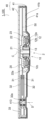
- FIG. 1 is a longitudinal sectional view of a disk drive device according to embodiments of the first and second inventions.
- FIG. 2 is a perspective view of a base plate according to embodiments of the first and second inventions.
- FIG. 3 is a cross-sectional perspective view of a base plate according to embodiments of the first and second inventions.
- FIG. 4 is a perspective view of a metal plate according to embodiments of the first and second inventions.
- FIG. 5 is a cross-sectional perspective view showing an enlarged part of the base plate according to the embodiment of the first and second inventions.
- FIG. 6 is a flow chart showing the manufacturing process of the base plate according to the embodiment of the first invention.
- FIG. 7 is an explanatory view explaining the manufacturing process of the base plate according to the embodiment of the first invention.
- FIG. 8 is an explanatory view explaining the manufacturing process of the base plate according to the embodiment of the first invention.
- FIG. 9 is an explanatory view explaining the manufacturing process of the base plate according to the embodiment of the first invention.
- 10A and 10B are explanatory diagrams for explaining the manufacturing process of the base plate according to the embodiment of the first invention.
- 11A and 11B are explanatory diagrams for explaining the manufacturing process of the base plate according to the embodiment of the first invention.
- 12A and 12B are explanatory diagrams for explaining the manufacturing process of the base plate according to the embodiment of the first invention.
- 13A and 13B are explanatory diagrams for explaining the manufacturing process of the base plate according to the embodiment of the first invention.
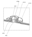
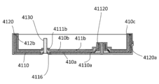
- FIG. 14 is a cross-sectional perspective view showing an enlarged part of the base plate according to the embodiment of the second invention.
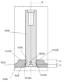
- FIG. 15 is a front cross-sectional view showing an enlarged pivot post of a base plate according to an embodiment of the second invention.
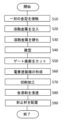
- FIG. 16 is a flow chart showing the manufacturing process of the base plate according to the embodiment of the second invention.
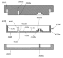
- FIG. 17 is an explanatory view explaining the manufacturing process of the base plate according to the embodiment of the second invention.
- 18A and 18B are explanatory diagrams for explaining the manufacturing process of the base plate according to the embodiment of the second invention.
- 19A and 19B are explanatory diagrams for explaining the manufacturing process of the base plate according to the embodiment of the second invention.
- FIG. 20 is an explanatory view explaining the manufacturing process of the base plate according to the embodiment of the second invention.
- FIG. 21 is an explanatory view explaining the manufacturing process of the base plate according to the embodiment of the second invention.
- FIG. 22 is an explanatory view explaining the manufacturing process of the base plate according to the embodiment of the second invention.
- FIG. 23 is an explanatory view explaining the manufacturing process of the base plate according to the embodiment of the second invention.
- FIG. 24 is an explanatory view explaining the manufacturing process of the modified base plate according to the embodiment of the second invention.
- FIG. 25 is a front sectional view showing an enlarged pivot post of a modification of the base plate according to the embodiment of the second invention.
- the direction parallel to the rotation axis C is referred to as the "axial direction”
- the direction orthogonal to the rotation axis C is referred to as the "radial direction”
- the direction along the arc centered on the rotation axis C is referred to as the "circumferential direction”.
- the axial direction is defined as the vertical direction
- the cover 42 side with respect to the base plate 41 is defined as the upper side, and the shape and positional relationship of each part will be described.
- this definition of the vertical direction is not intended to limit the orientation of the base plate 41 and the disk drive device 1 according to the present invention when in use.
- FIG. 1 is a longitudinal sectional view of a disk drive device 1 according to an embodiment of the invention.
- the disk drive device 1 is a hard disk drive.
- the disk drive device 1 includes a spindle motor 2 , a disk 50 , a head 31 , an arm 32 , a swing mechanism 33 and a housing 40 .
- the housing 40 accommodates the spindle motor 2, the disk 50, the head 31, and the arm 32 inside.
- the inside of the housing 40 is filled with a gas with a density lower than that of air.
- a gas with a density lower than that of air Specifically, helium gas is filled. Hydrogen gas or the like may be filled instead of helium gas.
- the housing 40 has a base plate 41 and a cover 42 .
- a disk 50 , a spindle motor 2 and an access section 30 are arranged on a base plate 41 inside the housing 40 .
- An upper opening of the base plate 41 is closed with a cover 42 .
- the base plate 41 will be described later in detail.
- the spindle motor 2 rotates the disk 50 around the rotation axis C while supporting the disk 50 . That is, the disc 50 is rotated around the rotation axis C by the spindle motor 2 .
- the spindle motor 2 has a stationary portion 10 and a rotating portion 20 .
- the stationary section 10 remains relatively stationary with respect to the housing 40 .
- the rotating portion 20 is rotatably supported with respect to the stationary portion 10 .
- the stationary part 10 has a stator 12 and a bearing unit 13 .
- the base plate 4 A part of 1 constitutes a stationary part 10 .
- the spindle motor 2 has a base plate 41 .
- the base plate 41 extends perpendicularly to the rotation axis C on the lower side of the rotating part 20 .
- the base plate 41 is part of the spindle motor 2 and also part of the housing 40 .
- the stator 12 and bearing unit 13 are fixed to the base plate 41 .
- the stator 12 has a stator core 12a, which is a magnetic material, and a plurality of coils 12b.
- the stator core 12a has a plurality of teeth 12c protruding radially outward.
- the plurality of coils 12b are composed of conductive wires wound around the teeth 12c.
- the bearing unit 13 rotatably supports the shaft 21 on the rotating part 20 side.
- a fluid dynamic pressure bearing mechanism is used for the bearing unit 13 .
- the rotating part 20 has a shaft 21 , a hub 22 and a magnet 23 .
- the shaft 21 is a columnar member extending in the axial direction. A lower end of the shaft 21 is housed inside the bearing unit 13 .
- the hub 22 is fixed to the upper end of the shaft 21 and expands radially outward.
- the upper surface of the outer peripheral portion 22 a of the hub 22 supports the disk 50 .
- the magnets 23 are fixed to the inner peripheral surface of the hub 22 and arranged radially outwardly of the stator 12 to face each other with a predetermined distance therebetween.
- the magnet 23 has an annular shape, and the inner peripheral surface of the magnet 23 is alternately magnetized with N poles and S poles in the circumferential direction.
- the disk 50 is a disk-shaped information recording medium with a hole in the center.
- Each disk 50 is mounted on the spindle motor 2 and arranged in parallel with each other in the axial direction at equal intervals via spacers (not shown).
- the head 31 magnetically reads or writes information on the disk 50 .
- the arm 32 is attached to the tip of a pivot post 413, which will be described later, of the base plate 41 via a bearing 32a.
- a head 31 is provided at the tip of the arm 32 .
- the swinging mechanism 33 is a mechanism for swinging the arm 32 and the head 31 .
- the arm 32 swings around the swing axis D.
- the head 31 is swung around the swing axis D by the swing mechanism 33 via the arm 32 .
- the head 31 moves relatively to the disk 50 and accesses the rotating disk 50 in close proximity.
- FIG. 2 is a perspective view of the base plate 41.
- FIG. 3 is a cross-sectional perspective view of the base plate 41.
- FIG. 2 Although the traces of the gate trace portion 41e shown in FIG. 2 are removed in the manufacturing process of the base plate 41, which will be described later, they are shown for the sake of explanation.
- the base plate 41 is formed in a box shape with an open top, and has a bottom wall portion 411 , a peripheral wall portion 412 , a pivot post 413 , a connector window portion 414 and a cylindrical wall portion 415 .
- the bottom wall portion 411 has a rectangular shape when viewed from the axial direction, and extends perpendicularly to the rotation axis C and the swing axis D. As shown in FIG.
- the peripheral wall portion 412 extends upward from the outer peripheral edge of the bottom wall portion 411 to surround the bottom wall portion 411 .
- the cover 42 (see FIG. 1) is arranged on the upper end surface of the peripheral wall portion 412 and screwed, for example.
- the peripheral wall portion 412 has a gate scar portion 41 e to which the gate 214 (see FIG. 8) was connected during casting, and the gate scar portion 41 e is arranged on the outer surface of the peripheral wall portion 412 .
- the pivot post 413 protrudes upward from the upper surface of the bottom wall portion 411 along the swing axis D and is formed in a columnar shape.
- the connector window 414 draws out a connector (not shown) connected to the swing mechanism 33 to the outside of the base plate 41 .
- the cylindrical wall portion 415 is arranged on the rotation axis C and protrudes axially upward.
- the shaft 21 (see FIG. 1) is press-fitted inside the cylindrical wall portion 415 . Thereby, the base plate 41 and the shaft 21 are fixed.
- the base plate 41 is composed of a metal plate 41a and a die-cast part 41b covering the metal plate 41a (see FIG. 3).
- the metal plate 41a is formed, for example, by pressing a metal plate such as stainless steel having higher rigidity than an aluminum alloy.
- the die-cast part 41b is made of a die-cast member such as an aluminum alloy. That is, the metal forming the metal plate 41a has higher rigidity than the metal forming the die cast portion 41b.
- the thickness of the base plate 41 can be reduced while suppressing a decrease in strength. Therefore, the thickness of the housing 40 can be reduced in the axial direction. Further, by thinning the base plate 41, the space in the axial direction inside the housing 40 can be expanded. As a result, the number of disks 50 that can be accommodated in the housing 40 can be increased.
- the base plate 41 is an insert-cast product, and the metal plate 41a and the die-cast part 41b are integrally formed. A method of manufacturing the base plate 41 will be described later in detail.
- FIG. 4 is a perspective view of the metal plate 41a
- FIG. 5 is a cross-sectional perspective view showing an enlarged cylindrical wall portion 415 of the base plate 41. As shown in FIG.
- the metal plate 41a is formed in a box shape with an open top, and has a bottom plate portion 411a, a peripheral plate portion 412a, and a flange portion 413a.
- the bottom plate portion 411a has a rectangular shape when viewed from the axial direction, and is formed in a plate shape extending perpendicularly to the rotation axis C.
- the peripheral plate portion 412a extends upward from the outer peripheral edge of the bottom plate portion 411a to surround the bottom plate portion 411a.
- the flange portion 413 a extends radially outward from the upper end of the peripheral plate portion 412 a surrounding the disc 50 .
- the bottom wall portion 411 is formed by joining the die-cast portion 41b to the upper surface of the bottom plate portion 411a.
- the peripheral wall portion 412 is formed by joining the die-cast portion 41b to the outer peripheral surface and the inner peripheral surface of the peripheral plate portion 412a.
- the bottom plate portion 411 a has a cylindrical portion 4112 , a stepped portion 4113 , a plurality of bottom plate through holes 4114 and connector through holes 4115 .
- the cylindrical portion 4112 is arranged on the rotating shaft C, penetrates in the axial direction, and projects upward in the axial direction.
- the cylinder wall portion 415 is formed by joining the die-cast portion 41 b to the inner and outer peripheral surfaces of the cylinder portion 4112 . That is, the inner peripheral surface of the cylindrical portion 4112 is covered with the die cast portion 41b.
- the shaft 21 Since the shaft 21 is held by the cylindrical wall portion 415 including the cylindrical portion 4112 having higher rigidity than the metal forming the die cast portion 41b, the shaft 21 can be firmly fixed to the bottom plate portion 411a. Further, when the shaft 21 is press-fitted into the cylindrical portion 4112, the die-cast portion 41b covering the inner peripheral surface of the cylindrical portion 4112 is deformed and becomes a cushioning material. As a result, stress concentration on the cylindrical portion 4112 can be reduced, and deformation of the cylindrical portion 4112 can be prevented.
- a groove 415a extending in the circumferential direction is formed in the inner peripheral surface of the die cast portion 41b arranged on the inner peripheral surface of the cylindrical portion 4112 (see FIG. 5).
- the die-cast portion 41b covering the inner peripheral surface of the cylindrical portion 4112 is more easily deformed.
- the pressing force of the shaft 21 is reduced, and stress concentration on the cylindrical portion 4112 can be further reduced.
- the adhesive when adhesive is applied to the outer peripheral surface of the lower end portion of the shaft 21 and the shaft 21 is press-fitted into the cylindrical portion 4112 , the adhesive accumulates inside the groove portion 415 a so that the shaft 21 can be firmly fixed by the cylindrical portion 4112 .
- the stepped portion 4113 is formed in an annular shape that protrudes axially upward and surrounds the tubular portion 4112 .
- the thickness of the die cast portion 41b joined to the lower surface of the stepped portion 4113 can be increased.
- the strength of the stepped portion 4113 can be improved.
- the rigidity of the root portion of the cylindrical portion 4112 can be improved.
- the stepped portion 4113 has a plurality of conductor through-holes 4113a which penetrate in the axial direction and are arranged in the circumferential direction.
- the inside of the conductor wire through-hole 4113a is not filled with the die cast portion 41b, and the conductor wire through-hole 4113a extends in the axial direction and penetrates the die cast portion 41b. As a result, a conductor (not shown) connected to the spindle motor 2 can be led out of the base plate 41 through the conductor through-hole 4113a.
- the bottom plate through hole 4114 axially penetrates the bottom plate portion 411a and is filled with the die cast portion 41b. By providing the bottom plate through hole 4114, the bonding strength between the die cast portion 41b and the bottom plate portion 411a is improved. Further, the number of bottom plate through holes 4114 arranged inside the disk facing area 50a formed on the bottom plate portion 411a by projecting the disk 50 in the axial direction is greater than the number of the bottom plate through holes arranged outside the disk facing area 50a. Less than 4114 numbers. In this embodiment, the bottom plate through-hole 4114 is not provided inside the disk facing area 50a.
- the connector through-hole 4115 penetrates the bottom plate portion 411a in the axial direction, and a connector (not shown) connected to the swing mechanism 33 is pulled out. A portion of the connector through-hole 4115 is covered with the die cast portion 41b to form the connector window portion 414 (see FIG. 2). By cutting the die-cast portion 41b that partially covers the connector through-hole 4115, the opening area of the connector through-hole 4115 (the diameter of the connector window 414) can be easily changed.
- the peripheral plate portion 412 a has a peripheral plate through hole 4121 , a concave portion 4122 and a peripheral plate groove portion 4123 .
- the peripheral plate through hole 4121 radially penetrates the peripheral plate portion 412a and is filled with the die cast portion 41b. By providing the peripheral plate through hole 4121, the bonding strength between the die cast portion 41b and the peripheral plate portion 412a is improved.
- the recessed part 4122 is formed so that part of the bottom plate part 411a and the peripheral plate part 412a is recessed inward across the boundary between the bottom plate part 411a and the peripheral plate part 412a.
- the interior of the recess 4122 is filled with the die cast portion 41b.
- the recess 4122 is arranged on the opposite side of the central axis C with a center line L extending in the width direction through the center in the longitudinal direction of the bottom plate portion 411a. By providing the concave portion 4122, the bonding strength between the die cast portion 41b and the peripheral plate portion 412a is improved.
- the recess 4122 is arranged on the opposite side of the central axis C with the center line L interposed therebetween. This can prevent contact between the recess 4122 and the disc 50 .
- the circumferential plate groove portion 4123 is formed on the joint surface with the die cast portion 41b.
- the circumferential plate groove portion 4123 is formed on the outer peripheral surface of the circumferential plate portion 412a and extends in the circumferential direction.
- the groove portion 4123 may be formed on the inner peripheral surface of the peripheral plate portion 412a.
- the flange portion 413a extends radially outward from the upper end of the curved portion 4124 of the peripheral plate portion 412a and is at least partially covered with the die cast portion 41b.
- the curved portion 4124 curves along the periphery of the disc 50 when viewed from the axial direction.
- the flange portion 413 a has a flange through-hole 4131 .
- the flange through hole 4131 penetrates in the axial direction and is filled with the die cast portion 41b.
- FIG. 6 is a flow chart showing the manufacturing process of the base plate 41. As shown in FIG. 7 to 13 are explanatory diagrams explaining the manufacturing process of the base plate.
- step S1 the peripheral edge portion of the mold 202 holding the metal plate 41a and the peripheral edge portion of the mold 201 are brought into contact with each other in the vertical direction so that the mold 201 and the mold 202 are separated.
- a cavity 210 is formed therebetween.
- the cavity 210 has a shape corresponding to the shape of the die cast portion 41b.
- Cavity 210 also communicates with a gate 214 extending along opposing surfaces of mold 201 and mold 202 . The outer end of gate 214 opens to the outside of mold 201 and mold 202 .
- an air vent channel (not shown) for venting air from the cavity 210 is provided separately from the gate 214.
- the outer end of the air vent channel opens to the outside of the mold 201 and the mold 202 .
- the mold 201 has a columnar recess 201a.
- the columnar recess 201a is formed by recessing the lower surface of the mold 201 upward in the axial direction.
- the inside of the columnar recess 201 a communicates with the cavity 210 . Molten metal flows into the interior of the columnar recess 201 a to form the pivot post 413 .
- the mold 202 has a column portion 202a.
- the column portion 202 a protrudes axially upward from the upper surface and is inserted through the cylindrical portion 4112 . At this time, the gap between the inner peripheral surface of the cylindrical portion 4112 and the outer peripheral surface of the column portion 202a communicates with the cavity 210. As shown in FIG.
- step S2 molten metal is injected into the cavity 210 through the gate 214, as shown in FIG.
- the molten metal is, for example, a molten aluminum alloy.
- air in the cavity 210 or gas generated from the molten metal is pushed out of the molds 201 and 202 through the air vent channel. This allows the molten metal to spread throughout cavity 210 .
- the molten metal flows into the gap between the inner peripheral surface of the cylindrical portion 4112 and the outer peripheral surface of the column portion 202a, and the inner peripheral surface of the cylindrical portion 4112 is covered with the die cast portion 41b. Further, the molten metal flows into the bottom plate through hole 4114 and the connector through hole 4115 of the bottom plate portion 411a and the peripheral plate through hole 4121 and the recess 4122 of the peripheral plate portion 412a.
- step S3 after the molten metal has spread in the cavity 210, the molten metal is cooled and hardened. Thereby, the base plate 41 is formed within the cavity 210 .
- a chill layer (not shown) is formed on the surface of the base plate 41 . The chill layer is formed at a location where the molten metal is in contact with the mold 201 and the mold 202 and hardens quickly when the molten metal hardens. The chill layer, where the molten metal hardens faster than the rest, has less impurities and a higher metal density.
- a die cast part 41b covering the metal plate 41a is formed by injecting molten metal into the molds 201 and 202 in which the metal plate 41a is arranged. Therefore, it is possible to easily form the base plate 41 having a complicated shape whose strength is reinforced by the metal plate 41a having a simple shape.
- step S4 the base plate 41 is released from the pair of molds 201 and 202 as shown in FIG. At this time.
- the peripheral wall portion 412 has a gate trace portion 41d protruding from the outer surface.
- the gate trace portion 41d is formed by hardening the molten metal accumulated in the gate 214 and the air vent channel (not shown).
- step S5 as shown in FIG. 10, the gate trace portion 41d is cut.
- a gate trace portion 41e obtained by cutting the gate trace portion 41d slightly protrudes from the outer surface of the peripheral wall portion 412 and leaves a trace.
- an electrodeposition coating film 41c is formed on the surface of the die cast portion 41b.
- the electrodeposition coating film 41c is formed by, for example, immersing the base plate 41 in a coating material such as epoxy resin, and passing an electric current between the coating material and the die-cast part 41b. As a result, the coating material adheres to the surfaces of the die cast portion 41b and the exposed metal plate 41a to form an electrodeposition coating film 41c. At this time, the outer surface of the gate mark portion 41e is also covered with the electrodeposition coating film 41c. By covering at least part of the surface of the die cast portion 41b and the exposed metal plate 41a with the electrodeposition coating film 41c, the insulation of the base plate 41 can be improved and leakage of gas passing through the base plate 41 can be reduced.
- step S7 as shown in FIG. 12, the pivot post 413, which requires precision, is shaped by cutting with precision out of the surface of the die-cast part 41b.
- the electrodeposition coating film 41c is also cut by cutting the surface of the base plate 41, and the machined surface 71 is formed. As a result, a region is formed on the peripheral surface of the pivot post 413 where the electrodeposition coating film 41c is not provided.
- step S7 the outer surface of the die cast portion 41b of the peripheral wall portion 412 including the gate trace portion 41e formed when the gate trace portion 41d is removed in step S5 is cut and shaped.
- the electrodeposition coating film 41c on the outer peripheral surface of the peripheral wall portion 412 is cut, and the processed surface 72 is formed. That is, a machined surface 72 obtained by cutting the surface of the die cast portion 41b is formed to include at least a portion of the gate trace portion 41e.
- the gate marks 41e accumulated in the gate 214 and the air vent channel (not shown) can be shaped by a series of operations.
- machined surface 72 may be formed only on one surface of the peripheral wall portion 412 including the gate trace portion 41e. Further, the processed surface 72 may be formed across one surface of the peripheral wall portion 412 including the gate trace portion 41e and at least one surface adjacent to the one surface.
- step S7 the gate trace portion 41e is removed by cutting and the trace disappears, but the gate trace portion 41e is indicated by a broken line in FIG. 12 in order to explain the trace that the gate was connected during casting.
- step S8 the base plate 41 is immersed in an impregnating agent.
- the impregnating agent 41f is infiltrated in the machined surfaces 71 and 72 from which the electrodeposition coating film 41c has been cut.
- an epoxy resin or an acrylic resin is used as the impregnating agent 41f.
- minute cavities formed on the surface of the die cast portion 41b are sealed with the impregnating agent 41f on the processed surfaces 71 and 72 from which the electrodeposition coating film 41c has been cut.
- the helium gas filled inside the housing 40 can be prevented from leaking to the outside through the processed surface 72 .
- the impregnating agent 41f has a lower viscosity than the coating material forming the electrodeposition coating film 41c. Therefore, the impregnating agent 41f is more likely to impregnate the minute cavities formed on the surface of the die cast portion 41b than the coating material forming the electrodeposition coating film 41c.
- the method for manufacturing the cast base plate 41 that forms a part of the housing 40 of the disk drive device 1 includes, in order, a casting process, a removal process, an electrodeposition coating process, a cutting process, and an impregnation process. have.
- the metal plate 41a and the die cast portion 41b are integrally cast using a mold (steps S1 to S4).
- the gate trace portion 41d is cut (step S5).
- the electrodeposition coating process the electrodeposition coating film 41c is formed on at least the die-cast part 41b and part of the exposed metal plate 41a (step S6).
- the cutting step the surface of the base plate 41 is cut and shaped (step S7).
- the impregnation step the processed surface exposed from the electrodeposition coating film 41c on the surface of the die cast part 41b is impregnated with an impregnation agent (step S8).
- the above embodiments are merely examples of the present invention.
- the configuration of the embodiment may be changed as appropriate without departing from the technical idea of the present invention.
- the embodiments may be implemented in combination within a possible range.
- the bottom wall portion 411 is formed by joining the die-cast portion 41b to the upper surface of the bottom plate portion 411a. may be formed.
- FIG. 4 is a perspective view of the metal plate 41a.
- the metal plate 41a is formed in a box shape with an open top, and has a bottom plate portion 411a and a peripheral plate portion 412a.
- the bottom plate portion 411a has a rectangular shape when viewed from the axial direction, and is formed in a plate shape extending perpendicularly to the rotation axis C.
- the peripheral plate portion 412a extends upward from the outer peripheral edge of the bottom plate portion 411a to surround the bottom plate portion 411a.
- the bottom plate portion 411a has a cylindrical portion 4112 and a pivot through hole 4116.
- the cylindrical portion 4112 is arranged on the rotating shaft C, penetrates in the axial direction, and projects upward in the axial direction.
- the cylinder wall portion 415 is formed by joining the die-cast portion 41 b to the inner and outer peripheral surfaces of the cylinder portion 4112 .
- the shaft 21 Since the shaft 21 is held by the cylindrical wall portion 415 including the cylindrical portion 4112 having higher rigidity than the metal forming the die cast portion 41b, the shaft 21 can be firmly fixed to the bottom plate portion 411a. Further, when the shaft 21 is press-fitted into the cylindrical portion 4112, the die-cast portion 41b covering the inner peripheral surface of the cylindrical portion 4112 is deformed and becomes a cushioning material. As a result, stress concentration on the cylindrical portion 4112 can be reduced, and deformation of the cylindrical portion 4112 can be prevented.
- the pivot through-hole 4116 is arranged on the swing axis D, penetrates the bottom plate portion 411a in the axial direction, and is filled with the die-cast portion 41b. Also, the pivot post 413 is arranged on the pivot through hole 4116 .
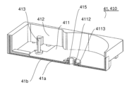
- the die-cast part 14 is a cross-sectional perspective view of the base plate 410.
- the die cast portion 410b is joined to the metal plate 410a and has a bottom surface portion 411b and a peripheral surface portion 412b.
- the bottom portion 411b is joined to the top surface of the bottom plate portion 4110a and extends perpendicularly to the rotation axis C.
- the bottom wall portion 4110 is configured by the bottom plate portion 4110a and the bottom surface portion 411b.
- the bottom surface portion 411b has a pedestal portion 4111b on the pivot through hole 4116 of the metal plate 410a.
- the pedestal portion 4111b protrudes upward from the upper surface of the bottom surface portion 411b along the swing axis D and is formed in a tubular shape.
- a lower end portion of the pivot post 4130 is arranged inside the pedestal portion 4111b. The pivot post 4130 is held inside the base portion 4111b and firmly fixed to the bottom portion 411b.
- the peripheral surface portion 412b is joined to the outer peripheral surface and the inner peripheral surface of the peripheral plate portion 4120a.
- the peripheral surface portion 412b joined to the inner peripheral surface of the peripheral plate portion 4120a extends upward from the outer peripheral edge of the bottom surface portion 411b to surround the bottom surface portion 411b.
- the peripheral wall portion 4120 is configured by the peripheral plate portion 4120a and the peripheral surface portion 412b.
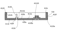
- FIG. 15 is a front sectional view showing an enlarged pivot post 4130.
- the pivot post 4130 is made of, for example, a metal such as stainless steel having higher rigidity than an aluminum alloy, and is formed in a columnar shape.
- the pivot post 4130 is a separate member from the die cast portion 410b, and the metal forming the pivot post 4130 has higher rigidity than the metal forming the die cast portion 410b. As a result, the rigidity of the pivot post 4130 is improved, and shrinkage cavities do not occur in the pivot post 4130 due to insert casting. Therefore, it is possible to prevent the gas filled inside the housing 40 from leaking to the outside through the pivot post 4130 .
- the pivot post 4130 has a post through hole 4130a and a post groove portion 413b.
- the post through-hole 4130a is arranged inside the pedestal portion 4111b and penetrates the pivot post 4130 in the radial direction of the swing axis D. As shown in FIG.
- the inside of the post through hole 4130a is filled with the die cast portion 410b. As a result, the pivot post 4130 is held more firmly inside the pedestal portion 4111b.
- the post groove portion 413b is arranged inside the pedestal portion 4111b, is recessed radially inward of the swing axis D, and extends in the circumferential direction.
- the inside of the post groove portion 413b is filled with the die cast portion 410b.
- the surface roughness of the outer peripheral surface of the pivot post 4130 inside the pedestal portion 4111b is greater than the surface roughness of the pivot post 4130 outside the pedestal portion 4111b. Thereby, the joint strength between the base portion 4111b and the pivot post 4130 is further improved.
- a bottom surface portion 411b of the die cast portion 410b has a joint portion 4112b and an inclined portion 4113b around the pivot post 4130 .
- Joint 4112b joins pivot post 4130 and is impregnated with impregnant 410f in at least a portion of joint 4112b.
- the inclined portion 4113b is inclined away from the pivot post 4130 as it goes axially downward from the lower end of the joint portion 4112b.
- the inclined portion 4113b By providing the inclined portion 4113b, it becomes easier to impregnate the joint portion 4112b with the impregnating agent 410f from the lower surface side of the bottom surface portion 411b.
- the axial length L1 of the joint portion 4112b is longer than the axial length L2 of the inclined portion 4113b. Accordingly, when the inclined portion 4113b is provided, it is possible to suppress a decrease in the bonding strength between the base portion 4111b and the pivot post 4130.
- a sealing material 4114b is arranged in the gap between the inclined portion 4113b and the pivot post 4130. As a result, leakage of the gas filled inside the housing 40 to the outside through the joint portion 4112b can be further suppressed.
- An epoxy-based thermosetting adhesive is preferably used as the sealing material.
- FIG. 16 is a flow chart showing the manufacturing process of the base plate 410. As shown in FIG. 17 to 23 are explanatory diagrams explaining the manufacturing process of the base plate.
- step S10 the periphery of the mold 2020 holding the metal plate 410a and the periphery of the mold 2010 holding the pivot post 4130 are brought into contact in the vertical direction.
- a cavity 2100 is thereby formed between the mold 2010 and the mold 2020 .
- Cavity 2100 has a shape corresponding to the shape of die cast portion 410b.
- Cavity 2100 also communicates with a gate 2140 that extends along opposite sides of mold 2010 and mold 2020 . The outer end of gate 2140 opens to the outside of mold 2010 and mold 2020 .
- an air vent channel (not shown) for venting air from the cavity 2100 is provided on the facing surfaces of the mold 2010 and the mold 2020 .
- the outer end of the air vent channel opens to the outside of the mold 2010 and the mold 2020 .
- the mold 2010 has a columnar recess 2010a and a base recess 201b.
- the columnar recess 2010a is formed by recessing the lower surface of the mold 2010 upward in the axial direction.
- a pivot post 4130 is arranged inside the columnar recess 2010a.
- the pedestal recessed portion 201b surrounds the columnar recessed portion 2010a, and the lower surface of the mold 2010 is recessed upward in the axial direction.
- the base recess 201 b communicates with the cavity 2100 .
- the mold 2020 has a column portion 2020a.
- the column portion 2020a protrudes axially upward from the upper surface and is inserted through the cylindrical portion 4112 . At this time, the gap between the inner peripheral surface of cylindrical portion 41120 and the outer peripheral surface of column portion 2020 a communicates with cavity 2100 .
- step S20 molten metal is injected into the cavity 2100 through the gate 2140, as shown in FIG.
- the molten metal is, for example, a molten aluminum alloy.
- air in the cavity 2100 or gas generated from the molten metal is pushed out of the mold 2010 and the mold 2020 through the air vent channel. This allows the molten metal to spread throughout the cavity 2100 .
- the molten metal flows into the pedestal concave portion 201b to form the pedestal portion 4111b.
- Molten metal also flows into pivot through hole 4116 and contacts the lower end of pivot post 4130 . Further, it flows into the gap between the inner peripheral surface of the cylindrical portion 41120 and the outer peripheral surface of the column portion 2020a, and the inner peripheral surface of the cylindrical portion 41120 is covered with the die cast portion 410b. At this time, the molten metal flows into the post through hole 4130a and the post groove portion 413b.
- step S30 after the molten metal has spread into the cavity 2100, the molten metal is cooled and hardened. This forms the base plate 410 within the cavity 2100 .
- a chill layer (not shown) is formed on the surface of the base plate 410 . The chill layer is formed at a location where the molten metal is in contact with the mold 2010 and the mold 2020 and hardens quickly when the molten metal hardens. The chill layer, where the molten metal takes effect faster than other parts, has less impurities and a higher metal density.
- a die cast part 410b that covers the metal plate 410a is formed by injecting molten metal into the molds 2010 and 2020 in which the metal plate 410a is arranged. Therefore, it is possible to easily form a complex-shaped base plate 410 whose strength is reinforced by a simple-shaped metal plate 410a.
- a bottom portion 411b is formed on the top surface of the metal plate 410a.
- a base portion 4111b is formed on the pivot through-hole 4116. As shown in FIG. A lower end portion of the pivot post 4130 is held inside the pedestal portion 4111b.
- step S40 the base plate 410 is released from the pair of molds 2010 and 2020 as shown in FIG. At this time.
- the peripheral wall portion 4120 has a gate trace portion 410d protruding from the outer surface.
- the gate trace portion 410d is formed by hardening the molten metal accumulated in the gate 2140 and the air vent channel (not shown).
- step S50 as shown in FIG. 20, the gate trace portion 410d is cut.
- a gate trace portion 410e obtained by cutting the gate trace portion 410d slightly protrudes from the outer surface of the peripheral wall portion 4120 and leaves a trace.
- an electrodeposition coating film 410c is formed on the surface of the die cast portion 410b.
- the electrodeposition coating film 410c is formed by immersing the base plate 410 in, for example, an epoxy-based resin coating material, and passing an electric current between the coating material and the die-cast part 410b. As a result, the coating material adheres to the surface of the die cast portion 410b to form the electrodeposition coating film 410c.
- the outer surface of the gate mark portion 410e is also covered with the electrodeposition coating film 410c.
- step S70 as shown in FIG. 22, of the surface of the die-cast part 410b, the part that requires precision is precision machined and shaped by cutting. Further, in step S70, the outer surface of the die cast portion 410b of the peripheral wall portion 4120 including the gate trace portion 410e formed when the gate trace portion 410d is removed in step S50 is cut and shaped.
- the electrodeposition coating film 410c on the outer peripheral surface of the peripheral wall portion 4120 is cut, and the processed surface 720 is formed.
- the gate marks 410e accumulated in the gate 2140 and the air vent channel (not shown) and the overflow can be shaped by a series of operations.
- the processed surface 720 may be formed only on one side of the peripheral wall portion 4120 including the gate trace portion 410e. Further, the processed surface 720 may be formed across one surface of the peripheral wall portion 4120 including the gate trace portion 410e and at least one surface adjacent to the one surface.
- step S80 the base plate 410 is immersed in an impregnating agent.
- the impregnating agent 410f is impregnated on the machined surface 720 from which the electrodeposition coating film 410c has been cut.
- the joint portion 4112b of the die cast portion 410b that joins with the pivot post 4130 is impregnated with an impregnating agent 410f (see FIG. 15).
- Epoxy resin or acrylic resin is used for the impregnating agent 410f, for example.
- minute cavities formed on the surface of the die cast portion 410b are sealed with the impregnating agent 410f on the machined surface 720 from which the electrodeposition coating film 410c has been cut.
- the gas filled inside the housing 40 can be prevented from leaking to the outside through the processing surface 720 .
- the impregnating agent 410f has a lower viscosity than the coating material forming the electrodeposition coating film 410c. Therefore, the impregnating agent 410f is more likely to impregnate the minute cavities formed on the surface of the die cast portion 410b than the coating material forming the electrodeposition coating film 410c.
- step S90 the sealing material 4114b is arranged in the gap between the inclined portion 4113b and the pivot post 4130.
- the method for manufacturing the cast base plate 410 that is part of the housing 40 of the disk drive device 100 includes the casting process, the removal process, the electrodeposition coating process, the cutting process, the impregnation process, and the sealing process. and, in order.
- the casting process places the pivot post 4130 in the mold 2010 and pours molten metal to form the die cast part 410b having the bottom part 411b.
- the die cast portion 410b having the bottom surface portion 411b and the pivot post 4130 which is a separate member from the die cast portion 410b, are integrally cast with a mold (steps S10 to S40).
- the gate trace portion 410d is cut (step S50).
- the electrodeposition coating film 410c is formed on the surface of the die cast part 410b (step S60).
- the cutting step the surface of base plate 410 is cut and shaped (step S70).
- the processed surface 720 exposed from the electrodeposition coating film 410c and the joint part 4112b (see FIG. 15) that joins with the pivot post 4130 of the die cast part 410b are impregnated with an impregnating agent (step S80).
- the sealing material 4114b is arranged in the gap between the inclined portion 4113b and the pivot post 4130 (step S90).
- 24A and 24B are explanatory diagrams for explaining the manufacturing process of the base plate 410 according to the modification, and the base plate 410 may be formed without the metal plate 410a. At this time, the die cast portion 410b and the pivot post 4130 are integrally formed.
- a bottom wall portion 4110 is configured by the bottom portion 411b.
- a peripheral wall portion 4120 is configured by the peripheral surface portion 412b.
- FIG. 25 is an enlarged front sectional view showing the pivot post 4130, in which the inclined portion 4113b is not formed.
- the area of the joint portion 4112b is increased, and the joint strength between the pedestal portion 4111b and the pivot post 4130 is further improved.
- the sealing step (step S90) in the manufacturing process of the base plate 410 is also omitted.
- at least part of the joint portion 4112b is impregnated with the impregnating agent 410f.
- a base plate which is part of a housing of a disk drive device, includes a die-cast part having a bottom part that extends perpendicularly to the rotation axis of the disk that extends vertically, and a die-cast part that is arranged at a position different from the rotation axis and provides information on the disk.
- a pivot post that protrudes upward from the upper surface of the bottom surface portion and extends vertically along the swing axis of the head that reads or writes the The base plate, wherein the metal forming the pivot post has higher rigidity than the metal forming the die cast portion.
- the bottom portion has a cylindrical pedestal portion that protrudes upward from the top surface along the swing axis, and the lower end portion of the pivot post is disposed inside the pedestal portion. baseplate.
- the base plate according to (2) wherein the surface roughness of the outer peripheral surface of the pivot post inside the pedestal portion is greater than the surface roughness of the outer peripheral surface of the pivot post outside the pedestal portion.
- the pivot post has a post groove portion extending in the circumferential direction recessed radially inward of the swing shaft on its peripheral surface, the post groove portion being disposed inside the pedestal portion, and the die-cast portion being inside the post groove portion.
- a baseplate according to (2) or (3) which is filled.
- the pivot post has a post through-hole penetrating in the radial direction of the swing shaft, the post through-hole being disposed inside the base portion and filled with the die-cast portion;
- the base plate according to any one of (4) to (4).
- the bottom surface portion has a joint portion that joins with the pivot post, and an inclined portion that inclines in a direction away from the pivot post as it goes axially downward from a lower end of the joint portion.
- a spindle motor comprising the base plate according to any one of (1) to (9).
- the die cast part has an inclined part inclined in a direction away from the pivot post as it goes axially downward from the lower end of the joint area, and after the impregnation step, the inclined part and the pivot post.
- the present invention can be used for a housing used in a disk drive device such as a hard disk drive.
Landscapes
- Engineering & Computer Science (AREA)
- Power Engineering (AREA)
- Manufacturing & Machinery (AREA)
- Motor Or Generator Frames (AREA)
- Moving Of Heads (AREA)
Priority Applications (2)
| Application Number | Priority Date | Filing Date | Title |
|---|---|---|---|
| JP2023548492A JPWO2023042866A1 (https=) | 2021-09-14 | 2022-09-14 | |
| US18/691,462 US20240386909A1 (en) | 2021-09-14 | 2022-09-14 | Base plate, spindle motor, disk drive device, and method for manufacturing base plate |
Applications Claiming Priority (4)
| Application Number | Priority Date | Filing Date | Title |
|---|---|---|---|
| JP2021149698 | 2021-09-14 | ||
| JP2021149699 | 2021-09-14 | ||
| JP2021-149698 | 2021-09-14 | ||
| JP2021-149699 | 2021-09-14 |
Publications (1)
| Publication Number | Publication Date |
|---|---|
| WO2023042866A1 true WO2023042866A1 (ja) | 2023-03-23 |
Family
ID=85602949
Family Applications (1)
| Application Number | Title | Priority Date | Filing Date |
|---|---|---|---|
| PCT/JP2022/034466 Ceased WO2023042866A1 (ja) | 2021-09-14 | 2022-09-14 | ベースプレート、スピンドルモータ、ディスク駆動装置及びベースプレートの製造方法 |
Country Status (3)
| Country | Link |
|---|---|
| US (1) | US20240386909A1 (https=) |
| JP (1) | JPWO2023042866A1 (https=) |
| WO (1) | WO2023042866A1 (https=) |
Cited By (1)
| Publication number | Priority date | Publication date | Assignee | Title |
|---|---|---|---|---|
| US12361976B2 (en) * | 2022-09-09 | 2025-07-15 | Nidec Corporation | Base plate with metal member embedded in the peripheral wall part, motor, and disk driving device having the same |
Citations (5)
| Publication number | Priority date | Publication date | Assignee | Title |
|---|---|---|---|---|
| JP2014003830A (ja) * | 2012-06-19 | 2014-01-09 | Nippon Densan Corp | ベースプレート、ベースユニット、モータ、ディスク駆動装置、およびベースプレートの製造方法 |
| JP2014154203A (ja) * | 2013-02-04 | 2014-08-25 | Seagate Technology Llc | ベースデッキフロアを備える装置および方法 |
| JP2015050788A (ja) * | 2013-08-30 | 2015-03-16 | サムスン電機ジャパンアドバンスドテクノロジー株式会社 | 回転機器 |
| JP2017075340A (ja) * | 2015-10-13 | 2017-04-20 | 株式会社黒坂鍍金工業所 | 密封容器の気密構造と気密施工方法、気密構造を備えたハードディスクドライブ装置 |
| JP2019058017A (ja) * | 2017-09-22 | 2019-04-11 | 日本電産株式会社 | ベースプレート、ハードディスク装置および製造方法 |
Family Cites Families (7)
| Publication number | Priority date | Publication date | Assignee | Title |
|---|---|---|---|---|
| US4814914A (en) * | 1985-06-27 | 1989-03-21 | Mitsubishi Denki Kabushiki Kaisha | Disc driving device having a reinforced base |
| US6034841A (en) * | 1998-05-29 | 2000-03-07 | International Business Machines Corporation | Disk drive with composite sheet metal and encapsulated plastic base |
| JP2014002821A (ja) * | 2012-06-19 | 2014-01-09 | Nippon Densan Corp | ベースプレート、ベースユニット、モータ、およびディスク駆動装置 |
| KR101474104B1 (ko) * | 2013-02-05 | 2014-12-17 | 삼성전기주식회사 | 베이스 어셈블리 및 이를 구비하는 기록 디스크 구동장치 |
| JP2014216040A (ja) * | 2013-04-28 | 2014-11-17 | 日本電産株式会社 | スピンドルモータおよびディスク駆動装置 |
| US20150015995A1 (en) * | 2013-07-11 | 2015-01-15 | HGST Netherlands B.V. | Hard disk drive spindle motor cup |
| JP2022038646A (ja) * | 2020-08-27 | 2022-03-10 | ミネベアミツミ株式会社 | ベース部材、スピンドルモータおよびハードディスク駆動装置 |
-
2022
- 2022-09-14 US US18/691,462 patent/US20240386909A1/en active Pending
- 2022-09-14 JP JP2023548492A patent/JPWO2023042866A1/ja active Pending
- 2022-09-14 WO PCT/JP2022/034466 patent/WO2023042866A1/ja not_active Ceased
Patent Citations (5)
| Publication number | Priority date | Publication date | Assignee | Title |
|---|---|---|---|---|
| JP2014003830A (ja) * | 2012-06-19 | 2014-01-09 | Nippon Densan Corp | ベースプレート、ベースユニット、モータ、ディスク駆動装置、およびベースプレートの製造方法 |
| JP2014154203A (ja) * | 2013-02-04 | 2014-08-25 | Seagate Technology Llc | ベースデッキフロアを備える装置および方法 |
| JP2015050788A (ja) * | 2013-08-30 | 2015-03-16 | サムスン電機ジャパンアドバンスドテクノロジー株式会社 | 回転機器 |
| JP2017075340A (ja) * | 2015-10-13 | 2017-04-20 | 株式会社黒坂鍍金工業所 | 密封容器の気密構造と気密施工方法、気密構造を備えたハードディスクドライブ装置 |
| JP2019058017A (ja) * | 2017-09-22 | 2019-04-11 | 日本電産株式会社 | ベースプレート、ハードディスク装置および製造方法 |
Cited By (1)
| Publication number | Priority date | Publication date | Assignee | Title |
|---|---|---|---|---|
| US12361976B2 (en) * | 2022-09-09 | 2025-07-15 | Nidec Corporation | Base plate with metal member embedded in the peripheral wall part, motor, and disk driving device having the same |
Also Published As
| Publication number | Publication date |
|---|---|
| JPWO2023042866A1 (https=) | 2023-03-23 |
| US20240386909A1 (en) | 2024-11-21 |
Similar Documents
| Publication | Publication Date | Title |
|---|---|---|
| JP7682640B2 (ja) | ベースプレート、スピンドルモータ、ディスク駆動装置及びベースプレートの製造方法 | |
| JP7671154B2 (ja) | ベースプレート、スピンドルモータ、ディスク駆動装置及びベースプレートの製造方法 | |
| JP7668122B2 (ja) | ベースプレート、スピンドルモータおよびディスク駆動装置 | |
| US10407775B2 (en) | Base plate, hard disk drive, and method of manufacturing base plate | |
| US8873196B2 (en) | Base plate made of materials which have a different young's modulus, base unit, motor, disk drive apparatus and method of manufacturing the base plate | |
| US11682431B2 (en) | Base member, spindle motor, and hard disk drive device | |
| JP2016171717A (ja) | スピンドルモータ、およびディスク駆動装置 | |
| JP7159834B2 (ja) | ベースプレートおよびハードディスク装置 | |
| US12361976B2 (en) | Base plate with metal member embedded in the peripheral wall part, motor, and disk driving device having the same | |
| WO2023042866A1 (ja) | ベースプレート、スピンドルモータ、ディスク駆動装置及びベースプレートの製造方法 | |
| JP2016170843A (ja) | スピンドルモータ、およびディスク駆動装置 | |
| JP5532855B2 (ja) | スピンドルモータ、ディスク駆動装置、及びスピンドルモータの製造方法 | |
| JP2019087291A (ja) | ベース部材およびそれを備えるディスク駆動装置 | |
| JP2008005623A (ja) | モータおよび記録ディスク駆動装置 | |
| JP2007209178A (ja) | ロータユニット及びロータユニットの生産方法 | |
| US12482502B2 (en) | Spindle motor having blind hole configuration detail and hard disk drive device having the same | |
| JP2025009831A (ja) | ベースプレート、モータ、ディスク駆動装置及びベースプレートの製造方法 | |
| JP2015050788A (ja) | 回転機器 | |
| US12512123B2 (en) | Base plate, spindle motor, disk drive device, and base plate manufacturing method | |
| JP2024163827A (ja) | ベースプレート、スピンドルモータ、ディスク駆動装置及びベースプレートの製造方法 | |
| JP2008027540A (ja) | ディスク型記録装置のベースプレートの製造方法、ディスク型記録装置のベースプレートおよびディスク型記録装置 | |
| JP2024027869A (ja) | ベースプレート、モータ、ディスク駆動装置及びベースプレートの製造方法 | |
| JP2020005470A (ja) | スピンドルモータ | |
| JP2024057270A (ja) | ベース、及び、ハードディスク駆動装置 | |
| JP2007032623A (ja) | スラスト板の製造方法、流体動圧軸受装置の製造方法、スラスト板、及び流体動圧軸受装置 |
Legal Events
| Date | Code | Title | Description |
|---|---|---|---|
| 121 | Ep: the epo has been informed by wipo that ep was designated in this application |
Ref document number: 22870013 Country of ref document: EP Kind code of ref document: A1 |
|
| WWE | Wipo information: entry into national phase |
Ref document number: 2023548492 Country of ref document: JP |
|
| WWE | Wipo information: entry into national phase |
Ref document number: 2401001597 Country of ref document: TH |
|
| WWE | Wipo information: entry into national phase |
Ref document number: 18691462 Country of ref document: US |
|
| NENP | Non-entry into the national phase |
Ref country code: DE |
|
| 122 | Ep: pct application non-entry in european phase |
Ref document number: 22870013 Country of ref document: EP Kind code of ref document: A1 |