WO2023042525A1 - マイクロニードルパッチ - Google Patents
マイクロニードルパッチ Download PDFInfo
- Publication number
- WO2023042525A1 WO2023042525A1 PCT/JP2022/026226 JP2022026226W WO2023042525A1 WO 2023042525 A1 WO2023042525 A1 WO 2023042525A1 JP 2022026226 W JP2022026226 W JP 2022026226W WO 2023042525 A1 WO2023042525 A1 WO 2023042525A1
- Authority
- WO
- WIPO (PCT)
- Prior art keywords
- needle
- base material
- microneedle patch
- functional member
- adhesive layer
- Prior art date
- Legal status (The legal status is an assumption and is not a legal conclusion. Google has not performed a legal analysis and makes no representation as to the accuracy of the status listed.)
- Ceased
Links
Images




Classifications
-
- A—HUMAN NECESSITIES
- A61—MEDICAL OR VETERINARY SCIENCE; HYGIENE
- A61M—DEVICES FOR INTRODUCING MEDIA INTO, OR ONTO, THE BODY; DEVICES FOR TRANSDUCING BODY MEDIA OR FOR TAKING MEDIA FROM THE BODY; DEVICES FOR PRODUCING OR ENDING SLEEP OR STUPOR
- A61M37/00—Other apparatus for introducing media into the body; Percutany, i.e. introducing medicines into the body by diffusion through the skin
- A61M37/0015—Other apparatus for introducing media into the body; Percutany, i.e. introducing medicines into the body by diffusion through the skin by using microneedles
-
- A—HUMAN NECESSITIES
- A61—MEDICAL OR VETERINARY SCIENCE; HYGIENE
- A61M—DEVICES FOR INTRODUCING MEDIA INTO, OR ONTO, THE BODY; DEVICES FOR TRANSDUCING BODY MEDIA OR FOR TAKING MEDIA FROM THE BODY; DEVICES FOR PRODUCING OR ENDING SLEEP OR STUPOR
- A61M37/00—Other apparatus for introducing media into the body; Percutany, i.e. introducing medicines into the body by diffusion through the skin
-
- A—HUMAN NECESSITIES
- A61—MEDICAL OR VETERINARY SCIENCE; HYGIENE
- A61B—DIAGNOSIS; SURGERY; IDENTIFICATION
- A61B5/00—Measuring for diagnostic purposes; Identification of persons
- A61B5/145—Measuring characteristics of blood in vivo, e.g. gas concentration or pH-value ; Measuring characteristics of body fluids or tissues, e.g. interstitial fluid or cerebral tissue
- A61B5/14503—Measuring characteristics of blood in vivo, e.g. gas concentration or pH-value ; Measuring characteristics of body fluids or tissues, e.g. interstitial fluid or cerebral tissue invasive, e.g. introduced into the body by a catheter or needle or using implanted sensors
-
- A—HUMAN NECESSITIES
- A61—MEDICAL OR VETERINARY SCIENCE; HYGIENE
- A61B—DIAGNOSIS; SURGERY; IDENTIFICATION
- A61B5/00—Measuring for diagnostic purposes; Identification of persons
- A61B5/145—Measuring characteristics of blood in vivo, e.g. gas concentration or pH-value ; Measuring characteristics of body fluids or tissues, e.g. interstitial fluid or cerebral tissue
- A61B5/14507—Measuring characteristics of blood in vivo, e.g. gas concentration or pH-value ; Measuring characteristics of body fluids or tissues, e.g. interstitial fluid or cerebral tissue specially adapted for measuring characteristics of body fluids other than blood
- A61B5/1451—Measuring characteristics of blood in vivo, e.g. gas concentration or pH-value ; Measuring characteristics of body fluids or tissues, e.g. interstitial fluid or cerebral tissue specially adapted for measuring characteristics of body fluids other than blood for interstitial fluid
- A61B5/14514—Measuring characteristics of blood in vivo, e.g. gas concentration or pH-value ; Measuring characteristics of body fluids or tissues, e.g. interstitial fluid or cerebral tissue specially adapted for measuring characteristics of body fluids other than blood for interstitial fluid using means for aiding extraction of interstitial fluid, e.g. microneedles or suction
-
- A—HUMAN NECESSITIES
- A61—MEDICAL OR VETERINARY SCIENCE; HYGIENE
- A61B—DIAGNOSIS; SURGERY; IDENTIFICATION
- A61B5/00—Measuring for diagnostic purposes; Identification of persons
- A61B5/145—Measuring characteristics of blood in vivo, e.g. gas concentration or pH-value ; Measuring characteristics of body fluids or tissues, e.g. interstitial fluid or cerebral tissue
- A61B5/14532—Measuring characteristics of blood in vivo, e.g. gas concentration or pH-value ; Measuring characteristics of body fluids or tissues, e.g. interstitial fluid or cerebral tissue for measuring glucose, e.g. by tissue impedance measurement
-
- A—HUMAN NECESSITIES
- A61—MEDICAL OR VETERINARY SCIENCE; HYGIENE
- A61B—DIAGNOSIS; SURGERY; IDENTIFICATION
- A61B5/00—Measuring for diagnostic purposes; Identification of persons
- A61B5/145—Measuring characteristics of blood in vivo, e.g. gas concentration or pH-value ; Measuring characteristics of body fluids or tissues, e.g. interstitial fluid or cerebral tissue
- A61B5/1468—Measuring characteristics of blood in vivo, e.g. gas concentration or pH-value ; Measuring characteristics of body fluids or tissues, e.g. interstitial fluid or cerebral tissue using chemical or electrochemical methods, e.g. by polarographic means
- A61B5/1473—Measuring characteristics of blood in vivo, e.g. gas concentration or pH-value ; Measuring characteristics of body fluids or tissues, e.g. interstitial fluid or cerebral tissue using chemical or electrochemical methods, e.g. by polarographic means invasive, e.g. introduced into the body by a catheter
-
- A—HUMAN NECESSITIES
- A61—MEDICAL OR VETERINARY SCIENCE; HYGIENE
- A61B—DIAGNOSIS; SURGERY; IDENTIFICATION
- A61B5/00—Measuring for diagnostic purposes; Identification of persons
- A61B5/15—Devices for taking samples of blood
- A61B5/150007—Details
- A61B5/150015—Source of blood
- A61B5/150022—Source of blood for capillary blood or interstitial fluid
-
- A—HUMAN NECESSITIES
- A61—MEDICAL OR VETERINARY SCIENCE; HYGIENE
- A61B—DIAGNOSIS; SURGERY; IDENTIFICATION
- A61B5/00—Measuring for diagnostic purposes; Identification of persons
- A61B5/15—Devices for taking samples of blood
- A61B5/150969—Low-profile devices which resemble patches or plasters, e.g. also allowing collection of blood samples for testing
-
- A—HUMAN NECESSITIES
- A61—MEDICAL OR VETERINARY SCIENCE; HYGIENE
- A61B—DIAGNOSIS; SURGERY; IDENTIFICATION
- A61B5/00—Measuring for diagnostic purposes; Identification of persons
- A61B5/15—Devices for taking samples of blood
- A61B5/150977—Arrays of piercing elements for simultaneous piercing
- A61B5/150984—Microneedles or microblades
-
- A—HUMAN NECESSITIES
- A61—MEDICAL OR VETERINARY SCIENCE; HYGIENE
- A61B—DIAGNOSIS; SURGERY; IDENTIFICATION
- A61B5/00—Measuring for diagnostic purposes; Identification of persons
- A61B5/15—Devices for taking samples of blood
- A61B5/157—Devices characterised by integrated means for measuring characteristics of blood
-
- A—HUMAN NECESSITIES
- A61—MEDICAL OR VETERINARY SCIENCE; HYGIENE
- A61B—DIAGNOSIS; SURGERY; IDENTIFICATION
- A61B5/00—Measuring for diagnostic purposes; Identification of persons
- A61B5/48—Other medical applications
- A61B5/4836—Diagnosis combined with treatment in closed-loop systems or methods
- A61B5/4839—Diagnosis combined with treatment in closed-loop systems or methods combined with drug delivery
-
- A—HUMAN NECESSITIES
- A61—MEDICAL OR VETERINARY SCIENCE; HYGIENE
- A61B—DIAGNOSIS; SURGERY; IDENTIFICATION
- A61B5/00—Measuring for diagnostic purposes; Identification of persons
- A61B5/68—Arrangements of detecting, measuring or recording means, e.g. sensors, in relation to patient
- A61B5/6801—Arrangements of detecting, measuring or recording means, e.g. sensors, in relation to patient specially adapted to be attached to or worn on the body surface
- A61B5/683—Means for maintaining contact with the body
- A61B5/6832—Means for maintaining contact with the body using adhesives
- A61B5/6833—Adhesive patches
-
- A—HUMAN NECESSITIES
- A61—MEDICAL OR VETERINARY SCIENCE; HYGIENE
- A61B—DIAGNOSIS; SURGERY; IDENTIFICATION
- A61B5/00—Measuring for diagnostic purposes; Identification of persons
- A61B5/68—Arrangements of detecting, measuring or recording means, e.g. sensors, in relation to patient
- A61B5/6846—Arrangements of detecting, measuring or recording means, e.g. sensors, in relation to patient specially adapted to be brought in contact with an internal body part, i.e. invasive
- A61B5/6847—Arrangements of detecting, measuring or recording means, e.g. sensors, in relation to patient specially adapted to be brought in contact with an internal body part, i.e. invasive mounted on an invasive device
- A61B5/685—Microneedles
-
- A—HUMAN NECESSITIES
- A61—MEDICAL OR VETERINARY SCIENCE; HYGIENE
- A61B—DIAGNOSIS; SURGERY; IDENTIFICATION
- A61B2562/00—Details of sensors; Constructional details of sensor housings or probes; Accessories for sensors
- A61B2562/12—Manufacturing methods specially adapted for producing sensors for in-vivo measurements
-
- A—HUMAN NECESSITIES
- A61—MEDICAL OR VETERINARY SCIENCE; HYGIENE
- A61M—DEVICES FOR INTRODUCING MEDIA INTO, OR ONTO, THE BODY; DEVICES FOR TRANSDUCING BODY MEDIA OR FOR TAKING MEDIA FROM THE BODY; DEVICES FOR PRODUCING OR ENDING SLEEP OR STUPOR
- A61M37/00—Other apparatus for introducing media into the body; Percutany, i.e. introducing medicines into the body by diffusion through the skin
- A61M37/0015—Other apparatus for introducing media into the body; Percutany, i.e. introducing medicines into the body by diffusion through the skin by using microneedles
- A61M2037/0023—Drug applicators using microneedles
-
- A—HUMAN NECESSITIES
- A61—MEDICAL OR VETERINARY SCIENCE; HYGIENE
- A61M—DEVICES FOR INTRODUCING MEDIA INTO, OR ONTO, THE BODY; DEVICES FOR TRANSDUCING BODY MEDIA OR FOR TAKING MEDIA FROM THE BODY; DEVICES FOR PRODUCING OR ENDING SLEEP OR STUPOR
- A61M37/00—Other apparatus for introducing media into the body; Percutany, i.e. introducing medicines into the body by diffusion through the skin
- A61M37/0015—Other apparatus for introducing media into the body; Percutany, i.e. introducing medicines into the body by diffusion through the skin by using microneedles
- A61M2037/0053—Methods for producing microneedles
-
- A—HUMAN NECESSITIES
- A61—MEDICAL OR VETERINARY SCIENCE; HYGIENE
- A61M—DEVICES FOR INTRODUCING MEDIA INTO, OR ONTO, THE BODY; DEVICES FOR TRANSDUCING BODY MEDIA OR FOR TAKING MEDIA FROM THE BODY; DEVICES FOR PRODUCING OR ENDING SLEEP OR STUPOR
- A61M37/00—Other apparatus for introducing media into the body; Percutany, i.e. introducing medicines into the body by diffusion through the skin
- A61M37/0015—Other apparatus for introducing media into the body; Percutany, i.e. introducing medicines into the body by diffusion through the skin by using microneedles
- A61M2037/0061—Methods for using microneedles
Definitions
- the present invention relates to microneedle patches.
- Non-Patent Literature 1 and Patent Literature 1 disclose an analysis patch for puncturing a patient's skin with a microneedle to collect body fluid such as interstitial fluid and analyzing the body fluid.
- the device described in Non-Patent Document 1 detects and analyzes body fluid sucked up from microneedles formed on one surface of a substrate using a sensor member provided on the back surface of the substrate, and has a simple configuration. can be analyzed effectively.
- the device described in Non-Patent Document 1 transports the bodily fluid sucked up by the microneedle to the sensor member in the thickness direction of the base material, so the transportation distance is short and analysis can be performed quickly.
- the transport speed is not sufficiently high.
- the back side of the base material is fixed to the adhesive layer of the adhesive sheet so that the area of the adhesive layer where the base material is not adhered can be attached to the skin.
- the base material is paper, there is a problem that the adhesive sheet and the base material are easily separated.
- the substrate is a silicon wafer, there is no problem that the adhesive sheet is easily peeled off.
- Non-Patent Document 1 by changing the sensor member to a drug administration member, it is conceivable to use it as a drug administration patch instead of a test patch. Faster transport speeds are preferred.
- the present invention has been made in view of such actual circumstances, and when a microneedle patch is used as a test patch or the like, the test or the like can be performed quickly, and the base material can be easily peeled off from the tape. It is an object of the present invention to provide a microneedle patch that solves the problems of paper substrates such as being brittle and easily damaged.
- the present invention provides a liquid-impermeable base material having through holes, an absorbent material capable of absorbing liquid filled in the through holes, and one part of the base material.
- a needle-like portion having a flow path formed therein provided on the surface side, and a functional member provided on the other surface side of the base material, wherein the needle-like portion and the absorbent material are connected to each other.
- a microneedle patch that is connected to each other, wherein the absorbent material and the functional member are connected to each other (Invention 1).
- a through hole is provided in the substrate, an absorbent material capable of absorbing liquid is filled therein, the needle-like portion and the absorbent material are connected to each other, and the absorbent material and the functional
- a liquid-impermeable substrate can be used to create a patch with a short liquid transport channel, enabling rapid analysis in the case of a test patch, and Even when used as a drug administration patch, the drug solution can be quickly supplied to the skin.
- a liquid-impermeable base material the body fluid obtained from the needle-shaped part or the drug solution transported to the needle-shaped part does not seep into the base material, and the entire amount of the obtained liquid is transported.
- a drug solution can be rapidly supplied into the body.
- a liquid-impermeable base material when the patch is provided with an adhesive sheet to be attached to the skin, it is possible to prevent the base material from being peeled off from the adhesive sheet. That is, if the substrate itself is made of a liquid-permeable material, the liquid easily permeates into the substrate and enters between the adhesive sheet and the substrate, which causes separation between the adhesive sheet and the substrate.
- the liquid can pass only through the through-holes in the base material, so that the base material does not permeate and the base material is peeled off from the pressure-sensitive adhesive sheet. is suppressed.
- a liquid-impermeable base material breakage of the base material can be suppressed. That is, even a paper base material itself is not easily damaged, but since the base material itself is a material that is permeable to liquids, it is likely to become brittle when it comes into contact with liquids. Damage is also suppressed by using a flexible base material.
- the needle-like portion is made of a porous material (invention 2).
- the needle-like portion has a hole formed therein, and the hole also opens on the side surface of the needle-like portion (Invention 3).
- the one surface of the substrate is provided with a first adhesive layer (invention 4).
- the first adhesive layer is preferably a pressure-sensitive adhesive layer (invention 5).
- a second adhesive layer is provided on the other side of the base material (invention 6).
- the through-hole and the functional material are provided at positions at least partially overlapping each other in plan view (Invention 7).
- the absorbent material protrudes from the other side of the substrate, or the other side of the substrate and the surface of the absorbent material are included in the same plane. It is preferably filled (Invention 8).
- the absorbent material is preferably a porous material (Invention 9).
- At least a sheet for covering the functional member is further provided, and the sheet has an adhesive layer on the surface facing the functional member (Invention 10).
- the sheet includes ventilation means for exhausting air remaining between the sheet and the base material (invention 11).
- the functional member is a detection member that detects the liquid obtained from the needle-like portion or a drug administration member that administers a drug as the liquid from the needle-like portion. (Invention 12).
- the functional members include at least a first functional member and a second functional member, and the first functional member and the The second functional member is preferably the detection member that detects different components (Invention 13).
- a second aspect of the present invention is a liquid-impermeable base material having through holes, an absorbent material filled in the through holes, and a flow path provided on one side of the base material. and a formed needle-like portion, wherein the needle-like portion and the absorbent material are connected to each other (Invention 14).
- invention 14 by using a liquid-impermeable base material, it is possible to prevent the base material from being peeled off from the adhesive sheet when the patch is provided with the adhesive sheet.
- a through hole is provided in the base material, an absorbent material capable of absorbing liquid is filled in the through hole, and the needle-like portion and the absorbent material are connected to each other to achieve such a liquid-impermeable structure. Rapid analysis when used as a test patch by obtaining a microneedle structure that can transport the entire amount of liquid obtained using a substrate and can create a patch with a short liquid transport channel.
- the drug solution can be quickly supplied to the skin.
- FIG. 1 is a plan view of a microneedle patch according to a first embodiment
- FIG. (1) A cross-sectional view of the microneedle patch according to the first embodiment taken along line AA.
- (2) A cross-sectional view of the microneedle patch according to the first embodiment taken along line BB.
- 4 is a photograph showing the results of Example 1 and Comparative Example 2.
- a microneedle patch 1 comprises a microneedle structure 10 .
- the microneedle structure 10 includes a plurality of needle-like portions 12 on one surface side of a substrate 11 and spaced apart from each other at predetermined intervals.
- a hole 13 is formed in each needle-like portion 12 .
- a through-hole 15 is formed in the base material 11 , and the absorbent material 16 is filled in the through-hole 15 .
- the needles 12 and the absorbent material 16 are connected.
- the microneedle patch 1 further has a functional member 21 on the back (other side) side of the substrate 11 of the microneedle structure 10 .
- the functional member 21 is provided so as to overlap with the through hole 15 provided in the base material 11 in plan view.
- Functional member 21 connects with absorbent material 16 .
- the functional member 21 of this embodiment is a detection member, and the microneedle patch 1 functions as a test patch. Each member will be described in detail below.
- Needle-like portion The shape, size, forming pitch, and number of forming needle-like portions 12 can be appropriately selected depending on the intended use of the microneedles.
- Examples of the shape of the needle-like portion 12 include columnar, prismatic, conical, and pyramidal shapes, and in this embodiment, it is pyramidal.
- the maximum diameter or maximum cross-sectional dimension of the needle-like portion 12 is, for example, 25 to 1000 ⁇ m, and the tip diameter or cross-sectional dimension of the tip is 1 to 100 ⁇ m.
- the height is, for example, 50 to 2000 ⁇ m.
- the needle-like portions 12 are arranged in a plurality of rows in one direction of the substrate 11, and arranged in a matrix by forming a plurality of needle-like portions 12 in each row.
- the needle-like portion 12 has a hole portion 13 formed therein as a flow path through which liquid flows.
- the hole portion 13 may be configured in any way and may be provided mechanically, but the needle-like portion 12 is preferably made of a porous material. Since the needle-like portion 12 is made of a porous material, a channel through which the body fluid passes is relatively formed as the hole portion 13 therein, so there is no need to mechanically form a nano-order channel. . That is, if the needle-like portion 12 is formed so that at least a part thereof has a porous structure, body fluids or drug solutions can pass through the pores 13 of the porous structure.
- the amount of flow is greater than when a simple single communicating hole is formed. It is possible to increase Furthermore, when forming the needle-like portion 12 so that at least a portion thereof has a porous structure in this way, if the porous structure is not covered on part or all of the side surface of the needle-like portion, the needle-like portion 12 A hole 13 is also opened on the side surface of the . In this case, the flow rate of the liquid can be increased as compared with the case where only the distal end portion of the needle-like portion 12 is opened.
- porous materials include, for example, calcium silicate, calcium carbonate, diatomaceous earth, silicon dioxide (silica), aluminum oxide (alumina), clay minerals such as montmorillonite and kaolin, and various glasses.
- Inorganic materials various metals, low-molecular-weight organic compounds such as calcium lactate, resin materials such as crystalline cellulose, polycaprolactone, polylactic acid, and polyglycol, composite materials of resin and metal, and the like.
- the method of forming the porous structure of the porous material will be described in detail later, but at the same time as the needle-like portion 12 is formed, or after the projections 32 having no porous structure are formed, these materials are provided with a porous structure.
- the forming method is preferable from the viewpoint of making the hole 13 a continuous structure. As such a forming method, for example, two or more different materials are mixed to form protrusions, and then at least one material is removed to form pores to obtain a porous structure. .
- the needle-shaped portion 12 is formed by forming projections made of a water-insoluble material and a water-soluble material in the manufacturing process described later, and removing the water-soluble material in the removal step to form a hole. 13 , and the water-insoluble material that is insoluble in water remains to form a porous needle-like portion 12 .
- the water-insoluble material that constitutes the needle-like portion 12 is preferably a water-insoluble resin, considering ease of handling in the manufacturing process.
- the water-insoluble resin is preferably a water-insoluble resin having a melting point higher than room temperature and 250° C. or lower, more preferably a water-insoluble resin having a melting point higher than 40° C. and 200° C. or lower, and having a melting point higher than 45° C. and Water-insoluble resins having a melting point of 150° C. or lower are particularly preferred, and water-insoluble resins having a melting point of higher than 45° C. and lower than 80° C. are particularly preferred.
- the melting point is higher than room temperature
- the water-insoluble resin becomes solid at room temperature and can form the needle-like portion 12.
- the melting point is lower than 150°C, the material can be used as a base material. As the degree of freedom increases, workability also improves.
- the melting point of the water-insoluble resin is preferably 130°C or less.
- the melting point of the water-insoluble resin is more preferably 40 to 120°C, even more preferably 45 to 100°C.
- water-insoluble resins having a melting point of 130° C. or less include polyethylene, polyolefin resins such as ⁇ -olefin copolymers, olefin copolymer resins such as ethylene-vinyl acetate copolymer resins, polyurethane elastomers, and ethylene-acrylic acid.
- acrylic copolymer-based resins such as ethyl copolymers.
- the fluid from the needle-like portion 12 can flow more easily than in the structure in which the holes are opened only at the top of the needle-like portion.
- the melting point of the water-insoluble resin is high, the strength of the needle-like portion 12 can be improved.
- the melting point of the water-insoluble resin is preferably 135 to 240°C, more preferably 140 to 220°C, even more preferably 145 to 200°C.
- water-insoluble resins having a melting point of over 130° C. include polypropylene, polyvinylidene fluoride, acetal resins, and polycarbonate.
- such a water-insoluble resin is preferably a water-insoluble biodegradable resin that is less likely to affect the human body.
- the biodegradable resin aliphatic polyesters and derivatives thereof are preferably used, and from the group consisting of polylactic acid, polyglycolic acid, polycaprolactone, and copolymers obtained by copolymerizing the monomers constituting them. At least one selected is included.
- the melting point of the water-insoluble resin is 130° C. or less
- polycaprolactone, polybutylene succinate, aliphatic-aromatic copolyester, etc. can be used as the biodegradable resin.
- the melting point of the water-insoluble resin is higher than 130°C, polyglycolic acid, polylactic acid, polyhydroxybutyric acid, etc. can be used as the biodegradable resin.
- the water-insoluble material is polycaprolactone, which is a biodegradable resin having a melting point of 60° C., or a copolymer of caprolactone and other monomers constituting biodegradable resins.
- the molecular weight of the water-insoluble resin is generally 5,000-300,000, preferably 7,000-200,000, more preferably 8,000-150,000.
- the melting point of the water-insoluble resin is 130° C. or less, the strength of the needle-like portion 12 tends to decrease.
- the weight average molecular weight of the water-insoluble resin is preferably 40,000 or more, more preferably 40,000 to 200,000, and still more preferably 60 ,000 to 150,000.
- the needle-like portion 12 may further contain a filler.
- the mechanical strength of the needle-like portion 12 can be improved by containing the filler in the needle-like portion 12 .
- the filler is preferably contained so as to be dispersed in the resin of the needle-like portion 12 .
- the filler is preferably made of resin, and preferably made of one selected from the group consisting of natural organic polymers or modified products thereof, and biodegradable resins. Examples of natural organic polymers include cellulose, and examples of fillers composed of natural organic polymers or modified products thereof include cellulose fibers, cellulose acetate true-spherical fine particles, and the like.
- As the biodegradable resin a biodegradable resin having a melting point exceeding 130° C. or having no melting point is preferred. Examples of the biodegradable resin having a melting point exceeding 130° C. include the same biodegradable resin as used for the water-insoluble resin, cellulose acetate diacetate, and the like.
- the holes 13 are voids formed by removing the water-soluble material from the projections made of the water-insoluble material and the water-soluble material. Pass through as a flow path. As shown in the cross section of the needle-like portion 12, the removal of the water-soluble material forms a plurality of voids that communicate with each other. Some of the holes 13 extend to one surface of the substrate 11 .
- the size of the opening of the hole 13 is determined by the application such as a test patch using the microneedle structure 10, but from the viewpoint of facilitating the passage of liquid, the opening is 0.1 to 50.0 ⁇ m. , more preferably 0.5 to 25.0 ⁇ m, even more preferably 1.0 to 10.0 ⁇ m.
- body fluid includes blood, interstitial fluid, interstitial fluid, lymph fluid, and the like.
- the needle-like portion 12 may have a base portion 14 over at least a region where the needle-like portion 12 is formed between one surface side of the base material 11]
- the base portion 14 It is provided in layers over the entire one surface of the material 11 .
- the base 14 serves as a base for each needle-like portion 12 and has a hole portion 13 like each needle-like portion 12 .
- the base 14 is formed with a thickness of 0.1 to 500 ⁇ m, for example. By having such a thickness, the strength of the base material 11 is increased, and preferable adhesiveness is obtained between the needle-like portion 12 , the base part 14 and the base material 11 .
- the base portion 14 is also preferably porous like the needle-like portion 12, and the same porous material as the needle-like portion 12 can be used.
- a porous material is used for the base portion 14, there is no need to mechanically form a hole because a flow path is formed therein through which the liquid flows, and the liquid from the needle-like portion 12 flows through the base portion 14. It is possible to pass through and reach the functional member 21 via the absorbent material 16 of the through-hole 15, which is preferable.
- the base portion 14 is made of the same porous material as the material described for the needle portion 12 and is formed by the same process. 12 and base material 11 can obtain better adhesion through base 14, which is preferable.
- the base portion 14 is provided over the entire surface of the substrate 11, the porous material is also present in the portion of the substrate 11 where the needle-like portion 12 is not formed. , the strength of the microneedle structure 10 as a whole is further improved since it is attached to the base material 11 .
- the substrate 11 has liquid impermeability. Since the liquid impermeability of the base material 11 can suppress liquid absorption by the base material 11 , the liquid can pass only through the through holes 15 in the base material 11 . Therefore, the body fluid obtained from the needle-like portion 12 or the drug solution transported to the needle-like portion 12 does not seep into the base material 11, and the entire amount can be circulated through the through-hole 15, and the test patch can be used. In some cases, it enables rapid analysis and, even when used as a drug delivery patch, it can deliver drug solutions rapidly to the skin. Furthermore, the liquid does not permeate into the base material 11, and the separation of the base material 11 from the tape 22 is suppressed.
- Materials having such liquid impermeability include resin films, metal-containing sheets, glass films, and the like.
- Metal-containing sheets include metal foils.
- resin films a metal layer may be formed on a resin film having low water resistance by vapor deposition or the like to improve the water resistance, and the resin film may be used as the metal-containing sheet.
- resin films examples include polyesters such as polyethylene terephthalate (PET), polybutylene terephthalate (PBT) and polyethylene naphthalate (PEN), polyolefins such as polyethylene (PE) and polypropylene (PP), polyarylate, polyurethane, polycarbonate, polyamide, Examples thereof include resin films made of resins such as polyimide, ethylene-vinyl acetate copolymer, polyvinyl chloride, polytetrafluoroethylene, silicone, polysulfone, polylactic acid, and acrylic resin. Also, even if the material is non-liquid impermeable, such as non-woven fabric or paper, it may be a laminated resin film formed by laminating a water-insoluble resin on these to make the whole liquid impermeable.
- polybutylene terephthalate is used as the resin used for the resin film.
- PBT polyethylene terephthalate
- PET polyethylene
- PE polypropylene
- ethylene-vinyl acetate copolymer polyvinyl chloride
- acrylic resin polyurethane
- polylactic acid A resin having low thermal resistance may be used.
- the resin used for the resin film is preferably a heat-resistant resin.
- Heat-resistant resins include heat-resistant organic polymers and silicone resins.
- the glass transition temperature of the heat-resistant organic polymer is preferably 80° C. or higher, more preferably 110° C. or higher, still more preferably 140° C. or higher, and even more preferably 200° C. or higher.
- the glass transition temperature of the heat-resistant organic polymer is obtained by performing TMA (thermo-mechanical analysis) on a sample of the heat-resistant organic polymer at a temperature increase rate of 5 ° C./min. is the temperature at the intersection.
- Heat-resistant organic polymers include polymethyl methacrylate, polystyrene, polyacrylonitrile, polyphenylene oxide, polyethylene naphthalate (PEN), polyphenylene sulfide, polytetrafluoroethylene, polycarbonate, allyl resin, polyetheretherketone, acetylcellulose resin, It is preferably at least one selected from polysulfone, polyethersulfone, polyimide, and polyamideimide.
- the base material 11 is made of a flexible material that is highly conformable to the skin.
- resin films and non-woven fabrics impregnated with water-insoluble resins are preferable from this point of view.
- resin films made of resins such as polyester, polyolefin, polyarylate, polycarbonate, polyamide, polyimide, polysulfone, etc. is preferred.
- nonwoven fabric impregnated with a water-insoluble resin include polyester nonwoven fabric impregnated with an ethylene-vinyl acetate copolymer.
- the base material 11 may be of a single layer structure or a structure in which a plurality of layers are laminated as long as the base material 11 has liquid impermeability.
- the substrate 11 a laminate of a first layer 111 and a second layer 112 made of polyethylene terephthalate is used as the substrate 11.
- the first layer 111 or the second layer 112 may be the lamination surface with the needle portion 12, but in the present embodiment, the needle portion 12 is formed on the first layer 111 side.
- the thickness of the substrate 11 (the thickness excluding the first adhesive layer 114 and the second adhesive layer 115, and the first primer layer and the second primer layer, which will be described later) is preferably 3 to 200 ⁇ m, and more It is preferably 10 to 140 ⁇ m, more preferably 30 to 115 ⁇ m. When the thickness is 3 ⁇ m or more, the strength of the base material 11 can be easily maintained. It is possible.
- first layer 111 and the second layer 112 When laminating the first layer 111 and the second layer 112, an adhesive may be applied or printed to form an adhesive layer to adhere the first layer 111 and the second layer 112, or double-sided tape may be used.
- the first layer 111 and the second layer 112 may be bonded together.
- the first layer 111 and the second layer 112 are laminated with double-sided tape 113 .
- the first adhesive layer 114 is preferably provided on the surface (one surface) of the base material 11 on which the needle-like portions 12 are formed, as in the present embodiment.
- a pressure-sensitive adhesive is preferable, and examples thereof include acrylic pressure-sensitive adhesives, silicone-based pressure-sensitive adhesives, rubber-based pressure-sensitive adhesives, and more preferably acrylic pressure-sensitive adhesives. can.
- the solid composition 31 is adhered to the base material 11 in advance, and the base material 11 and the solid composition 31 are adhered in advance.
- the microneedle structure 10 can be easily obtained by putting the composition 31 into a mold and heat-pressing it in the heat-pressing step. Although such an effect cannot be obtained, a first primer layer (not shown) is used instead of the first adhesive layer 114 for the purpose of improving the adhesiveness between the needle-like portion 12 and the substrate 11. ) may be provided. Moreover, even when the base material 11 has the first adhesive layer 114 , a first primer layer may be provided as an intermediate layer between the base material 11 and the first adhesive layer 114 . Examples of the primer layer include an acrylic primer layer and a polyester primer layer.
- acrylic adhesive one containing an acrylic polymer obtained by polymerizing a monomer whose main component is an acrylic acid alkyl ester can be used.
- the acrylic polymer may be a copolymer of alkyl acrylate and other monomers.
- Other monomers include acrylic esters other than alkyl acrylates, such as acrylic esters having a hydroxyl group, acrylic esters having a carboxyl group, acrylic esters having an ether group, vinyl acetate, styrene, and the like.
- Monomers other than acrylic acid esters are included.
- the acrylic polymer may be crosslinked by reacting a functional group derived from the acrylic ester having a hydroxyl group, the acrylic ester having a carboxyl group, or the like with a crosslinking agent.
- the acrylic adhesive may contain tackifiers, plasticizers, antistatic agents, fillers, curable components, etc. in addition to the above components.
- Both solvent-based and emulsion-based coating liquids can be used to obtain acrylic pressure-sensitive adhesives.
- the second adhesive layer 115 is preferably provided on the surface of the base material 11 on which the needle-like portions 12 are not formed (the other surface, the back surface) as in the present embodiment.
- the adhesiveness between the base material 11 and the tape 22 is further improved, and peeling can be further suppressed.
- the functional member 21 can receive pressure from the tape 22, and the adhesion between the functional member 21 and the tape 22 is also improved. do.
- Examples of such a second adhesive layer include an acrylic pressure-sensitive adhesive, a silicone pressure-sensitive adhesive, a rubber pressure-sensitive adhesive, and the like, and an acrylic pressure-sensitive adhesive is preferable.
- the acrylic pressure-sensitive adhesive used for the second adhesive layer the same one as used for the first adhesive layer 114 can be used.
- a second primer layer (not shown) may be provided between the second adhesive layer 115 and the base material 11 or instead of the second adhesive layer 115 .
- the same kind of material as the first primer layer can be used.
- the same adhesive (for example, both acrylic adhesives) may be used for the first adhesive layer 114 and the second adhesive layer 115, or the first adhesive layer 114 and the second adhesive layer 115 may be A different adhesive may be used for the second adhesive layer 115 .
- the through holes 15 are formed in the base material 11 so that the liquid can flow between the needle-like portion 12 and the functional member 21 .
- the shape of the through hole 15 is circular in this embodiment, it is not limited to this, and may be rectangular or the like.
- the through hole 15 is provided in the center of the base material 11 in this embodiment, it is not limited to this, and may be formed anywhere on the base material 11, or may be formed in plurality. In any case, in this embodiment, when transporting the liquid between the needle-like portion 12 and the functional member 21, the liquid seeps into the base material 11 because the base material 11 has liquid impermeability.
- the transport distance is short, and when configured as a detection patch, detection can be performed at a high analysis speed.
- detection can be performed at a high analysis speed.
- the area of the through holes 15 is preferably 0.05 to 15%, more preferably 0.75 to 10%, and even more preferably 1 to 5% of the area of the base material 11. If the area of the through-holes 15 is 15% or less of the area of the base material 11, the rigidity of the substrate 11 can be easily ensured. Further, when the area of the through-holes 15 is 0.05% or more of the area of the base material 11 , body fluid can be more efficiently acquired through the substrate 11 .
- the inside of the through hole 15 is filled with an absorbent material 16 capable of absorbing liquid.
- an absorbent material capable of absorbing liquid.
- the absorbent material 16 and the needle-like portion 12 are connected, and the absorbent material 16 and the functional member 21 are connected so that the liquid functions with the needle-like portion 12. It is possible to circulate between the liquid member 21 .
- the absorbent material 16 granules of hydrophilic substances such as cellulose and silica, nonwoven fabrics, paper, fabrics, knitted fabrics, fiber aggregates such as absorbent cotton, porous materials, and the like can be used. Among these, a fiber assembly or a porous material is preferable from the viewpoint that it is easy to obtain a shape that matches the through holes 15 .
- the absorbent material 16 may be formed from two or more of the materials described above.
- porous material in the absorbent material 16 those listed as porous materials in the description of the needle-like portion 12 can be used. Any porous material may also be used. Further, when the absorbent material 16 is manufactured using the same porous material as the porous material forming the needle-like portion 12, it is more preferable because it can be formed simultaneously with the needle-like portion 12 and is simple. In this embodiment, the same water-insoluble material as the needle-like portion 12 is used as the absorbent material 16, and the water-insoluble material is filled into the through holes 15 at the same time as the needle-like portion 12 is formed.
- the absorbent material 16 filled in the through-holes 15 fills the through-holes 15 of the substrate 11 so that the back surface of the substrate 11 and the surface of the absorbent material 16 are included in the same plane. Alternatively, it is preferably provided so as to protrude above the through hole 15 of the base material 11 .
- the upper surface of the absorbent material 16 is included in the same plane as the upper surface of the through hole 15 or is provided so as to protrude above it, so that the absorbent material 16 and the functional member 21 are securely connected. , making it easier for liquid to flow between the absorbent material 16 and the functional member 21 .
- the absorbent material 16 protruding from the upper surface of the through-hole 15 is provided with a protrusion 17 extending from the absorbent material 16 .
- the projecting portion 17 is directly connected to the functional member 21 .
- the absorbent material 16 and the functional member 21 are more securely connected, and liquid can easily flow between the absorbent material 16 and the functional member 21.
- the functional member 21 and the absorbent material 16 can be connected by providing the functional material 21 in a pressed state. can.
- the absorbent material 16 and the functional member 21 do not have direct contact points.
- the absorbent material 16 and the functional member 21 do not have direct contact points.
- the absorbent material 16 and the functional member 21 do not have direct contact points.
- the absorbent material 16 and the functional member 21 are connected included in
- the functional member 21 has a detection function such as detecting the obtained body fluid and performing analysis or determination based on the detected body fluid, or a drug administration function such as storing a drug to be administered into the body. etc.
- the functional member 21 can be configured by incorporating a component that functions as a detection function or a drug administration function into a sheet such as paper.
- the functional member 21 is provided so as to overlap the through-hole 15 in plan view so that at least a part thereof is directly connected to the absorbent material 16 in the through-hole 15 . With such a configuration, the transport of the liquid in the microneedle structure 10 is based solely on the flow of the liquid in the thickness direction of the base material 11 through the through-holes 15, so the transport distance is extremely short. be able to.
- the functional member 21 When the functional member 21 is not provided so as to overlap the through-hole 15 in plan view, the functional member 21 and the water absorbent material 16 are indirectly connected by a material through which liquid can flow. good too.
- the material through which the liquid can flow the same material as that used for the absorbent material 16 can be used.
- the functional member 21 is in the form of a circular sheet and is placed directly above the through-hole 15 in a plan view so that the center of the through-hole 15 and the center of the functional member 21 are substantially aligned. , covers the entire surface of the absorbent material 16 exposed in the through-holes 15 .
- the shape and arrangement of the functional member 21 are not limited to those described above, and may be rectangular or the like, and may not be directly above the through hole 15 .
- the functional member 21 of this embodiment flows in through the hole 13 of the needle-like portion 12 by piercing the skin of the subject with the needle-like portion 12, and passes through the absorbent material 16 and the projecting portion 17 of the through-hole 15. It has a detection function for analyzing and testing body fluid that has reached the functional member 21 .
- a detection function for example, there is a glucose measuring paper that changes color depending on the glucose concentration in the body fluid.
- the glucose measuring paper is used as the functional member 21, the interstitial fluid sampled by the microneedle structure 10 is absorbed by the glucose measuring paper and discolored, and the blood glucose level is measured over time based on the degree of discoloration. It can be used as a microneedle patch 1 for blood sugar level measurement.
- the microneedle patch 1 can also be used as a microneedle patch 1 having a drug administration function of administering a drug from the base material 11 through the needle-like portion 12 into the body through the skin.
- the functional member 21 is configured as a paper-like base material containing a drug.
- a physiologically active substance-containing sheet is provided as the functional member 21, and the physiologically active substance from the physiologically active substance-containing sheet can be administered into the skin via the base material 11 and the needle-like portion 12. It can be used as a needle patch 1.
- the microneedle patch 1 may have multiple functional members 21, and the multiple functional members 21 may have the same function or may have different functions. Of course, it is not limited to whether all of the functional members 21 have the same function or different functions.
- the plurality of first functional members have the function of detecting and analyzing the same component
- the plurality of second functional members also have the function of detecting and analyzing the same component.
- the first functional member and the second functional member may each be configured to detect different components.
- the absorbent material 16 in one through-hole 15 may be connected to a part of the plurality of functional members 21, or a plurality of through-holes 15 may be provided, A plurality of functional members 21 may be configured to connect to absorbent material 16 in separate through-holes 15, respectively.
- the base material 11 has two through holes 15, each provided with a functional member 21 having a different function. That is, the functional member 21 having the above-described detection function is provided in the central through-hole 15 of the base material 11, and another through-hole 15A is also provided in the corner of the base material 11, and this through-hole 15A has a functional member 21A which is a reference sheet for detecting water.
- a functional member 21A is provided directly above this separate through-hole 15A so as to connect with the absorbent material 16A in the through-hole 15A.
- the reference sheet is paper impregnated with a component that changes color upon detection of water in bodily fluids. By providing the reference sheet, it is possible to know that the interstitial fluid has reached the functional member 21 by discoloration of the reference sheet, and then to start analysis of glucose in the interstitial fluid.
- the tape 22 should cover at least the functional member 21 and protect the functional member 21.
- the tape 22 covers not only the functional member 21 but also the base material 11. In the covered state, the part corresponding to the outside of the base material 11 is directly attached to the skin.
- the tape 22 is preferably made of a material having flexibility and stretchability in consideration of the ability to follow the skin to which it is applied, but is not limited to such materials.
- a preferred material for the tape 22 is a stretchable woven fabric, and conventionally known materials can be used.
- the tape 22 is provided with an adhesive layer 23 to fix the functional member 21 to the base material 11 and to be attached to the skin. Since the adhesive layer 23 is attached to the skin, it is preferably an adhesive having biological safety, and examples thereof include an acrylic adhesive and a rubber adhesive.
- a ventilation hole 224 is formed as a ventilation means so that air can be pushed out from the ventilation hole 24 when the tape 22 is attached. .
- a ventilation hole 224 is formed as a ventilation means so that air can be pushed out from the ventilation hole 24 when the tape 22 is attached.
- the ventilation means is not limited to such a ventilation hole 24.
- unevenness is provided on the surface of the adhesive layer 23 to form a ventilation hole by unevenness between the tape 22 and the base material 11, and this ventilation hole A tape 22 that allows air to pass through the outside of the tape 22 may be used.
- the microneedle patch 1 may be provided with a release sheet covering the exposed adhesive layer 23 of the tape 22, the needle-like portion 13, and one side of the substrate 11.
- a release sheet a known release sheet can be provided.
- the tape 22 not only protects the functional member 21 but also has a function as an adhesive tape to the skin, but is not limited thereto. It may be configured as a covering, and a tape larger than the tape 22 may be placed over the tape 22 so that the tape is applied to the skin. That is, the tape 22 may have only the function of protecting the functional member 21 and fixing it to the back surface of the base material 11, and another member may have the function of an adhesive tape to the skin.
- the adhesive layer 23 of the tape 22 in addition to the above-mentioned ones, those whose biosafety level does not reach the level for sticking to the skin can also be used.
- the adhesive layer 23 may be omitted by adhering the tape 22 with the second adhesive layer 115 of the substrate 11 .
- the microneedle structure 10 may be fixed on the skin of the living body by, for example, wrapping a pressurizing rubber band over the tape 22. .
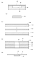
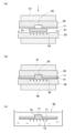
- 3 to 5 show a method for manufacturing the microneedle patch 1 according to the embodiment of the present invention.
- a solid composition 31 having a water-insoluble material and a water-soluble material is provided on the base material 11 (adhesion step), and then the solid composition 31 is heat-processed to form the protrusions 32 ( heating and pressurizing step), and then removing the water-soluble material from the protrusions 32 (removing step) so that the protrusions 32 become the needle-like portions 12 .
- a mixture 33 is prepared by heating a water-insoluble material and a water-soluble material to melt and mix them. In preparing the mixture 33, it is preferable to heat at 40° C. or higher and 180° C. or lower, which has little effect on the base material 11, so that the viscosity can be reduced when the resin is melted. Heating is more preferable, and heating at 70 to 120° C. is even more preferable.
- the water-soluble material a water-soluble material with a melting point higher than normal temperature is preferable.
- the water-soluble material may be organic or inorganic, and includes sodium chloride, potassium chloride, mirabilite, sodium carbonate, potassium nitrate, alum, sugar, water-soluble resin, and the like.
- a water-soluble thermoplastic resin is preferable, and one having a melting point higher than room temperature is preferable.
- water-soluble thermoplastic resins include biodegradable resins described later, as well as hydroxypropyl cellulose and polyvinylpyrrolidone.
- the water-soluble thermoplastic resin is more preferably a biodegradable resin in consideration of the effects on the human body.
- Such biodegradable resins include at least one selected from the group consisting of polyalkylene glycols such as polyethylene glycol and polypropylene glycol, polyvinyl alcohol, collagen, and mixtures thereof, with polyalkylene glycol being particularly preferred.
- the molecular weight of the polyalkylene glycol is, for example, preferably 200 to 4,000,000, more preferably 600 to 500,000, particularly preferably 1,000 to 100,000.
- polyalkylene glycols it is preferable to use polyethylene glycol.
- the water-insoluble material and the water-soluble material are preferably mixed at a weight ratio of 9:1 to 1:9, more preferably 8:2 to 2:8, and 7:3 to 3:3. 7 is particularly preferred.
- the needle-like portion 12 having a desired porosity is formed, and it becomes easy to achieve both liquid permeability and strength of the needle-like portion 12 .
- the mixture may contain not only the water-insoluble material, the filler, and the water-soluble material, but also other materials as non-volatile solids.
- the mixture 33 is injected into a solid composition recess 42 formed in a solid composition mold 41, as shown in FIG. 3(a).
- the solid composition recess 42 may be formed with a shape and capacity that can store a desired amount of the mixture 33 .
- a solid composition made of, for example, polydimethylsiloxane (PDMS) is applied to the upper surface of the solid composition recesses 42 in order to flatten the surface.
- PDMS polydimethylsiloxane
- the material of the solid composition mold 41 is not particularly limited, for example, it should be made of a silicone compound or the like that facilitates the creation of an accurate mold and allows the solid composition 31 that is solidified to be easily peeled off. is preferred, and in this embodiment it is made of polydimethylsiloxane.
- the base material 11 is produced.
- the base material 11 may be a single layer as described above.
- an adhesive tape having a second layer 112 as a tape base and a second adhesive layer 115 is adhered to the upper surface of the double-sided tape 113 to prepare the base 11 composed of multiple layers.
- each adhesive sheet is attached to the double-sided tape 113 so that the first adhesive layer 114 and the second adhesive layer 115 of each adhesive sheet are on the opposite side of the double-sided tape 113 .
- the substrate 11 with the first adhesive layer 114 and the second adhesive layer 115 exposed is formed.
- the substrate 11 having the first adhesive layer 114 and the second adhesive layer 115 is produced by attaching two adhesive tapes to the double-sided tape 113 as the substrate 11, but the present invention is not limited to this. .
- the present invention is not limited to this.
- by forming an adhesive layer on one side of the adhesive tape where the base material is exposed it is possible to produce the base material 11 having adhesive layers formed on both sides.
- through holes 15 are formed in the base material 11.
- the method of forming the through holes 15 is not particularly limited, and can be formed by punching, for example.
- the solid composition 31 is attached to the first adhesive layer 114 of the base material 11 to integrate the base material 11 and the solid composition 31 together.
- the first adhesive layer 114 the solid composition 31 is adhered to the base material 11 in advance, and the base material 11 and the solid composition 31 are placed in a mold and heated as described later.
- the microneedle structure 10 can be easily obtained by heat-pressing in the pressurizing step.
- handling such as transportation is facilitated.
- the solid composition 31 provided with the substrate 11 is placed on a mold 52 having recesses 51 so that the solid composition 31 faces the recesses 51 .
- a protrusion-forming recess 53 is also provided in the center of the bottom surface of the recess 51 .
- the protrusion-forming concave portion 53 is for forming the needle-like portion 12 , and is formed in a shape and size corresponding to the needle-like portion 12 .
- the lid 54 of the mold 52 is installed on the second adhesive layer 115 side of the base material 11 .
- This lid 54 is also made of polydimethylsiloxane, for example. It is preferable that the lid 54 is formed with an upward recessed lid recess 55 at a position corresponding to the through hole 15 of the base material 11 as in the present embodiment.
- the lid recess 55 By providing the lid recess 55, the solid composition 31 heated and pressurized in the next heating and pressurizing step flows into the through-hole 15 and is filled into the absorbent material 16, and the lid recess 55 is further filled.
- a protrusion 17 connected to the absorbent material 16 is formed or at least formed such that the upper surface of the absorbent material 16 is contained in the same plane as the upper surface of the substrate 11 .
- the lid recess 55 is also formed in accordance with the desired size and shape of the protrusion 17, or is formed so that the solid composition 31 reaches the same plane as the back surface of the base material to such an extent that the protrusion 17 is not formed. be.
- the lid recess 55 is provided in the lid 54 in this embodiment, the present invention is not limited to this.
- the lid recess 55 is not formed in the lid 54, the protrusion 17 is not formed and only a portion of the absorbent material 16 is contained in the same plane as the upper surface of the base material 11, or the absorbent material 16 is not provided.
- the absorbent material 16 may be formed so that the upper surface is recessed with respect to the upper surface of the base material 11, liquid transport between the absorbent material 16 and the functional member 21 may still occur. It is formed to connect to the extent possible.
- the absorbent material 16 has a porous structure formed by removing the water-soluble material in the removal step described later, and exhibits absorbency. Although not absorbent, it is referred to as absorbent material 16 for convenience.
- a heating and pressurizing step shown in FIG. 4(b) is performed.
- the heating and pressurizing step is for forming projections and the like of a desired shape, and the heating and pressurizing may be performed at once.
- a preliminary step for starting melting of the solid composition 31 provided with the substrate 11, and a preliminary step for sufficiently filling the recess 51 etc. with the molten solid composition 31 It is preferable to consist of this step.
- the heating conditions in the preliminary step and the main step it is sufficient to heat at least at 40° C. or higher and 180° C. or lower which has little effect on the substrate 11, preferably at 55 to 140° C., and 70 to 70° C. Heating at 120° C. is more preferred.
- the solid composition 31 is heated at a melting temperature.
- the lower stage 37 may be heated, or the upper stage 38 may be heated. In this step, the heating may be maintained after the preliminary step, and the temperature may be changed as appropriate.
- the mold 52 is pressed (pressurized) between the upper stage 57 and the lower stage 56 .
- the pressure in this preliminary step is preferably 0.1-5.0 MP. With the pressure within this range, the solid composition 31 can be melted in a short time. By holding for 10 seconds to 10 minutes, the solid composition 31 is melted.
- the pressurizing conditions may be changed between the preliminary process and the main process. For example, in this step, pressurization can be performed under conditions of higher pressure and longer time than in the preliminary step.
- the solid composition 31 is sufficiently melted, and the recess 51, the projection forming recess 53, the through hole 15, and the lid recess 55 are filled. be done.
- the mold 52 is removed from the lower stage 37, and the molten solid composition 31 is held at -10 to 3°C for 1 to 60 minutes (refrigeration solidification step) to be refrigerated and solidified.
- the projecting portion 32 and the like having a shape corresponding to the projecting portion forming recessed portion 53 and having high transferability are formed.
- the cleaning liquid in this removing step contains water, and the removing step is performed by placing the adhered protrusions 32 and the base material 11 in the cleaning liquid 58 in this embodiment.
- the cleaning liquid may be a mixed solvent such as water and alcohol.
- the holes 13 are formed in the projections 32 and the like, and the needle-like portions 12 are formed. That is, by removing the water-soluble material, the base 14, the absorbent material 16, and the protruding portion 17 as well as the needle-like portion 12 are formed with the same porosity. Thereby, the microneedle structure 10 of this embodiment is obtained.
- the microneedles are arranged such that the regions in which the needle-like portions 12 of the microneedle structure 10 are formed fit in recesses 62 provided on a mounting table 61 made of polydimethylsiloxane, for example.
- a structure 10 is placed.
- the tape 22 with the adhesive layer 23 formed thereon is cut into a predetermined size, and the functional member 21 is attached to the adhesive layer 23 of the tape 22 .
- the functional member 21 is adhered to the tape 22 so as to arrange the functional member 21 at a predetermined position on the back surface side of the substrate 11 of the microneedle structure 10 obtained.
- the microneedle patch 1 It is possible to manufacture the microneedle patch 1 by laminating it on the agent layer (installation step).
- the functional member 21 is laminated by laminating it on the adhesive layer of the tape 22, but the lamination method is not limited to this, and a conventionally known method can be used.
- the tape 22 After placing the functional member 21 on the back side, the tape 22 is formed by forming an adhesive layer such as a commonly used rubber-based adhesive, an acrylic adhesive, or a silicone-based adhesive on the tape base material. You may manufacture the microneedle patch 1 by laminating
- the needle-like portion 12 is formed using a water-insoluble material in order to easily form the hole portion 13 by removing the water-soluble material, but the method of manufacturing the needle-like portion 12 is not particularly limited.
- a liquid composition containing a water-soluble material, a water-insoluble material, and a solvent is formed, the solvent is evaporated, the composition other than the solvent is filled in the recesses for forming protrusions, and the protrusions are formed by drying. may be formed.
- the liquid composition is added dropwise with a dispenser or the like on the base material 11 by adjusting the viscosity to be 0.1 to 1000 mP s while containing the water-soluble material and the water-insoluble material. You may form the needle-like part 12 by.
- the solid composition 31 contains a water-soluble material and a water-insoluble material, but the material is not particularly limited as long as a porous structure can be formed in the needle-like portion 12 or the like. .
- the solid composition 31 is formed by any known method. A method of forming a needle-like portion 12 made of a porous material while generating gas inside and foaming, a method of sintering and binding a powder of a solid composition 31 containing a resin in a mold, and removing the porous material from the mold.
- a method for obtaining the needle-like portion 12, etc., can be exemplified.
- the composition does not contain a solvent, so discoloration and deformation of the substrate 11 can be suppressed, which is preferable.
- the solid composition 31 is adhered by the first adhesive layer 114 and fixed to the base material 11 in the bonding step, but is not limited to this, and the solid composition 31 can be heated by heating the solid composition 31. It may be melted and adhered to the base material 11 and then cooled to be fixed to the base material 11 . In this case, the first adhesive layer 114 may not be provided.
- the order of the bonding process and the heating/pressurizing process may be changed, and the bonding process may be performed after the heating/pressurizing process. That is, the protrusions 32 may be adhered to the base material 11 after the protrusions 32 are formed.
- Example 1 3 g of polyethylene glycol (weight average molecular weight: 4 kDa) as a water-soluble material and 7 g of polycaprolactone (melting point: 60° C.) as a water-insoluble material are heated at 110° C. while being heated and stirred to melt and mix to prepare a mixture. bottom.
- a solid composition mold 41 made of polydimethylsiloxane was prepared. In this solid composition mold 41, the opening of the solid composition recess 42 was rectangular with a diameter of 15 mm ⁇ 15 mm and a depth of 1.5 mm. was 5 mm. The mixture 33 was injected into the solid composition recess 42 .
- a solid composition sheet 43 made of polydimethylsiloxane was used as a lid and placed on the solid composition mold 41 into which the mixture 33 was injected, and the surface of the solid composition 31 was flattened. This state was maintained at 3° C. for 5 minutes, and the molten mixture 33 solidified into a solid state.
- two adhesive tapes (PET base material: thickness 100 ⁇ m / acrylic adhesive layer: thickness 25 ⁇ m) are attached to the side where the adhesive is not provided on each base material with double-sided tape (Nichiban Co., Ltd., product Name: Nicetac NW-25) was applied to both sides of the double-sided tape to obtain the substrate 11 with the first adhesive layer 114 and the second adhesive layer 115 exposed.
- the produced base material 11 was cut into a size of 30 mm square, and a circular through hole 15 (5 mm diameter) was formed in the central part.
- the obtained first adhesive layer 114 of the substrate 11 and the solid composition 31 were adhered.
- a mold 52 having recesses 53 for forming protrusions was prepared in order to perform the heating and pressing process.
- the mold 52 was made of polydimethylsiloxane and had recesses 53 for forming protrusions formed on its surface as detailed below.
- ⁇ Shape of projection-forming recess 53 quadrangular pyramid shape with square cross section ⁇ Length of one side of maximum cross-section of projection-forming recess 53: 500 ⁇ m ⁇ Height of protrusion-forming concave portion 53: 900 ⁇ m
- arrangement of protrusion-forming recesses 53 Square grid pattern ⁇ Pitch of protrusion-forming recesses 53: 1000 ⁇ m - Number of protrusion forming concave portions 53: 13 in one row, 13 in 13 rows, total 169
- a heating and pressurizing step was performed using the solid composition 31, the base material 11, and the mold 52.
- the solid composition 31 and the mold 52 are placed on the lower stage 56 of a heating press (AH-1T, manufactured by AS ONE Corporation), and a 30 mm square polydimethylsiloxane lid 54 is placed from above. repeated.
- the lid 54 had a circular lid recess 55 (diameter of 5.0 mm, depth of 125 ⁇ m) formed in the center thereof.
- the lid 54 was placed so that the lid concave portion 55 faced the through hole 15 of the base material 11 .
- the solid composition 31 is pressed through the lid 54 and the mold 52 for 2 minutes to preliminarily. did the process. Then, while performing the same heating, this step was performed by pressing at 4 MPa for 30 seconds. Furthermore, the base material 11 and the solid composition 31 housed in the lid 54 and the mold 52 were stored in a refrigerator at 3° C. for 10 minutes to solidify the solid composition 31 . After that, the substrate 11 and the molded solid composition 31 are separated from the mold and immersed in purified water at 25° C. for 24 hours to dissolve and remove polyethylene glycol as a water-soluble material. A base 14, absorbent material 16 was formed. After that, the microneedle structure 10 was obtained by allowing the microneedle structure 10 to stand still at 30° C. for 5 hours in a dry open to evaporate the moisture and dry.
- Adhesive sheet cut into 30 mm square (A 20 ⁇ m thick acrylic adhesive (AR-2040, manufactured by Big Technos Co., Ltd.) is applied to the matte processed surface of an 80 ⁇ m thick polyolefin base film).
- Glucose measuring paper (a circular shape with a diameter of 5 mm, for detecting glucose) was attached as the functional material 21 to the central portion of the tape 22 .
- a plurality of through holes (diameter of 200 ⁇ m) as vent holes 24 were formed in the peripheral portion of the functional member 21 of the tape 22 .
- the microneedle structure 10 is placed in a concave portion 62 provided on a mounting table 61 made of polydimethylsiloxane so that the region in which the needle-like portion 12 is formed is accommodated, and the through hole 15 of the base material 11 and the tape 22 are placed.
- a tape 22 was attached so as to overlap with the functional member 21 of , and a microneedle patch 1 was obtained. After each evaluation of the microneedle patch 1 was completed, it was confirmed by observing the cross section with a microscope that the microneedle patch had the protruding portion 17 .
- Example 2 A microneedle patch 1 was obtained under the same conditions as in Example 1 except that the lid recess 55 was not formed in the lid 54 . Moreover, after finishing each evaluation of the microneedle patch 1, it was confirmed by observation of the cross section that this microneedle patch did not have the projecting portion 17.
- FIG. 2 A microneedle patch 1 was obtained under the same conditions as in Example 1 except that the lid recess 55 was not formed in the lid 54 . Moreover, after finishing each evaluation of the microneedle patch 1, it was confirmed by observation of the cross section that this microneedle patch did not have the projecting portion 17. FIG.
- Example 3 In Example 1, a piece of adhesive tape (PET substrate: thickness 100 ⁇ m/acrylic adhesive layer: thickness 25 ⁇ m) was used as the substrate 11 on which only the first adhesive layer 114 was formed. A microneedle patch was obtained under the same conditions except that the lid recess 55 was not formed in the lid 54 . That is, the microneedle patch 1 according to this example differs from the microneedle patch 1 obtained in Example 1 in that it does not have the second adhesive layer 115 . Moreover, after finishing each evaluation of the microneedle patch 1, it was confirmed by observation of the cross section that this microneedle patch did not have the projecting portion 17.
- FIG. 1 shows that after finishing each evaluation of the microneedle patch 1, it was confirmed by observation of the cross section that this microneedle patch did not have the projecting portion 17.
- Example 4 In Example 1, a piece of adhesive tape (PET substrate: thickness 100 ⁇ m/acrylic adhesive layer: thickness 25 ⁇ m) was used as the substrate 11 on which only the first adhesive layer 114 was formed. A microneedle patch was obtained under the same conditions except for the points. That is, the microneedle patch 1 according to this example differs from the microneedle patch 1 obtained in Example 1 in that it does not have the second adhesive layer 115 . After each evaluation of the microneedle patch 1 was completed, it was confirmed by observing the cross section with a microscope that the microneedle patch had the protruding portion 17 .
- PET substrate thickness 100 ⁇ m/acrylic adhesive layer: thickness 25 ⁇ m
- Comparative example 1 As a comparative example, a water-permeable base material (circular qualitative filter paper No. 2 (manufactured by ADVANTEC) without through-holes) was used instead of the base material 11, and the lid recess 55 was not formed in the lid part 54. A microneedle patch was obtained under the same conditions except for the above.
- Comparative example 2 As a comparative example, a water-permeable base material (circular qualitative filter paper No. 2 (manufactured by ADVANTEC), no through holes) was used instead of the base material 11, the lid recess 55 was not formed in the lid 54, A microneedle patch was obtained under the same conditions except that the following additional steps were performed.
- a water-permeable base material circular qualitative filter paper No. 2 (manufactured by ADVANTEC), no through holes
- double-sided tape (commercial product using paper core material) was cut into a circle with a diameter of 5 mm, and a circular opening with a diameter of 3 mm was formed in the center.
- a double-faced tape having openings was attached to the area corresponding to the needle-shaped portion forming area on the back surface of the water-permeable substrate. Then, the opening of the double-sided tape was fully filled with edible powdered cellulose. The tape was attached to the microneedle structure so that the glucose measuring paper as the functional member was superimposed on the double-faced tape with the opening.
- Example 3 a sheet having a 20 ⁇ m thick adhesive layer made of acrylic adhesive on both sides of a water-permeable base material (circular qualitative filter paper No. 2 (manufactured by ADVANTEC)) is used.
- a microneedle patch was obtained under the same conditions as in Example 1 except for this. After each evaluation of the microneedle patch 1 was completed, it was confirmed by observing the cross section with a microscope that the microneedle patch had the protruding portion 17 .
- microneedle patches obtained in Examples 1 to 4 and Comparative Examples 1 to 3 are placed on an agarose gel (1% by mass) added with glucose (5 mol%), and lightly touched with a finger from above. Press for 5 seconds and puncture for 5 minutes. After that, it was confirmed whether the substrate and the tape could be separated using tweezers. Those that could not be peeled were evaluated as "A” (high evaluation), and those that could be peeled were evaluated as "B” (low evaluation). The results are shown in Table 1 as "Peelability Evaluation”.
- microneedle patch glucose measurement papers obtained in Examples 1 to 4 and Comparative Examples 1 to 3 are likely to detect glucose and change color. If the discolored part is 80% or more of the area of the glucose measurement paper, the evaluation is "A" (high evaluation), if it is 50% or more and less than 80%, it is “B”, and if it is less than 50%, it is “C” ( low evaluation). In addition, confirmation of discoloration was performed 5 minutes after puncturing. The results are shown in Table 1 as "sensing evaluation”.
- microneedle patch glucose measurement papers obtained in Examples 1 to 4 and Comparative Example 2 were visually observed every 1 minute after the puncture to see if the color change due to the detection of glucose could be clearly confirmed. , and the time until the start of coloring are shown in Table 1. 6 shows photographs of discoloration of the microneedle patches of Example 1 and Comparative Example 2.
- Example 1 As shown in Table 1, in Examples 1 to 4, both the peelability evaluation and the sensing evaluation are highly evaluated, the strength of the microneedle patch itself is high, and the liquid is sufficiently absorbed from the needle-like portion 12. It turns out that detection can be done. Further, as shown in FIG. 6, the microneedle patch 1 of Example 1 immediately detected glucose and changed color. In Example 1, it was found that the analysis speed was high because the time until the start of coloring was short. On the other hand, in Comparative Examples 1 to 3, since a water-permeable base material was used, moisture permeated the base material, and the peeling evaluation, sensing evaluation, and time until the start of coloring were all, or at least It turned out that one of the evaluations was low.
- microneedle patch of the present invention can be used, for example, as a drug administration patch or test patch.
- microneedle patch 10 microneedle structure 11 base material 12 needle-like portion 13 hole portion 21 functional member 22 tape 23 adhesive layer 24 vent hole 31 solid composition 32 protrusion 33 mixture 41 solid composition mold 42 Concave portion 51 for solid composition Concave portion 52 Mold 53 Protrusion forming concave portion 54 Lid 55 Lid concave portion
Landscapes
- Health & Medical Sciences (AREA)
- Life Sciences & Earth Sciences (AREA)
- Engineering & Computer Science (AREA)
- Physics & Mathematics (AREA)
- Public Health (AREA)
- Biomedical Technology (AREA)
- Heart & Thoracic Surgery (AREA)
- Medical Informatics (AREA)
- Animal Behavior & Ethology (AREA)
- General Health & Medical Sciences (AREA)
- Veterinary Medicine (AREA)
- Pathology (AREA)
- Biophysics (AREA)
- Molecular Biology (AREA)
- Surgery (AREA)
- Hematology (AREA)
- Optics & Photonics (AREA)
- Dermatology (AREA)
- Anesthesiology (AREA)
- Emergency Medicine (AREA)
- Chemical & Material Sciences (AREA)
- Chemical Kinetics & Catalysis (AREA)
- General Chemical & Material Sciences (AREA)
- Bioinformatics & Cheminformatics (AREA)
- Medicinal Chemistry (AREA)
- Pharmacology & Pharmacy (AREA)
- Media Introduction/Drainage Providing Device (AREA)
- Measurement Of The Respiration, Hearing Ability, Form, And Blood Characteristics Of Living Organisms (AREA)
- Medicinal Preparation (AREA)
Priority Applications (5)
| Application Number | Priority Date | Filing Date | Title |
|---|---|---|---|
| CN202280059330.0A CN117897199A (zh) | 2021-09-17 | 2022-06-30 | 微针贴片 |
| KR1020247004905A KR20240056491A (ko) | 2021-09-17 | 2022-06-30 | 마이크로 니들 패치 |
| JP2023548137A JPWO2023042525A1 (https=) | 2021-09-17 | 2022-06-30 | |
| DE112022004458.6T DE112022004458T5 (de) | 2021-09-17 | 2022-06-30 | Mikronadelpflaster |
| US18/692,290 US20240424271A1 (en) | 2021-09-17 | 2022-06-30 | Microneedle patch |
Applications Claiming Priority (2)
| Application Number | Priority Date | Filing Date | Title |
|---|---|---|---|
| JP2021-152537 | 2021-09-17 | ||
| JP2021152537A JP7141625B1 (ja) | 2021-09-17 | 2021-09-17 | マイクロニードルパッチ及びマイクロニードル構造体 |
Publications (1)
| Publication Number | Publication Date |
|---|---|
| WO2023042525A1 true WO2023042525A1 (ja) | 2023-03-23 |
Family
ID=83400863
Family Applications (1)
| Application Number | Title | Priority Date | Filing Date |
|---|---|---|---|
| PCT/JP2022/026226 Ceased WO2023042525A1 (ja) | 2021-09-17 | 2022-06-30 | マイクロニードルパッチ |
Country Status (7)
| Country | Link |
|---|---|
| US (1) | US20240424271A1 (https=) |
| JP (2) | JP7141625B1 (https=) |
| KR (1) | KR20240056491A (https=) |
| CN (1) | CN117897199A (https=) |
| DE (1) | DE112022004458T5 (https=) |
| TW (1) | TW202312938A (https=) |
| WO (1) | WO2023042525A1 (https=) |
Cited By (6)
| Publication number | Priority date | Publication date | Assignee | Title |
|---|---|---|---|---|
| WO2025005050A1 (ja) * | 2023-06-30 | 2025-01-02 | リンテック株式会社 | マイクロニードル構造体及びマイクロニードルパッチ |
| WO2025070573A1 (ja) * | 2023-09-26 | 2025-04-03 | Toppanホールディングス株式会社 | 検査デバイスおよび検査方法 |
| WO2025105446A1 (ja) * | 2023-11-14 | 2025-05-22 | リンテック株式会社 | マイクロニードルパッチ及び分析方法 |
| WO2025105444A1 (ja) * | 2023-11-14 | 2025-05-22 | リンテック株式会社 | マイクロニードル構造体、マイクロニードルパッチ及びマイクロニードル構造体の製造方法 |
| WO2026071015A1 (ja) * | 2024-09-30 | 2026-04-02 | リンテック株式会社 | マイクロニードル構造体の製造方法及びマイクロニードル構造体 |
| WO2026071014A1 (ja) * | 2024-09-30 | 2026-04-02 | リンテック株式会社 | マイクロニードル構造体及びその製造方法 |
Families Citing this family (4)
| Publication number | Priority date | Publication date | Assignee | Title |
|---|---|---|---|---|
| US20250064349A1 (en) * | 2023-08-25 | 2025-02-27 | General Electric Company | Microneedle-integrated interstitial fluid biomarker sensor systems and methods thereof |
| WO2025105296A1 (ja) * | 2023-11-14 | 2025-05-22 | リンテック株式会社 | マイクロニードル構造体及びその製造方法 |
| WO2025182934A1 (ja) * | 2024-02-26 | 2025-09-04 | 国立大学法人 東京大学 | 多孔質マイクロニードルを備えるマイクロニードルパッチ、及び当該マイクロニードルパッチを製造する方法 |
| KR102883072B1 (ko) | 2025-07-04 | 2025-11-06 | 원종표 | 마이크로 니들형 두피자극기 |
Citations (6)
| Publication number | Priority date | Publication date | Assignee | Title |
|---|---|---|---|---|
| JP2002532165A (ja) * | 1998-12-18 | 2002-10-02 | メドトロニック ミニメド インコーポレイテッド | 医療装置と共に使われる、微小突刺し部材を備える挿入セット及びそのような挿入セットの使用方法 |
| JP2003038467A (ja) * | 2001-06-12 | 2003-02-12 | Lifescan Inc | 生物流体サンプリングおよび分析物測定の装置および方法 |
| JP2005514179A (ja) * | 2002-01-15 | 2005-05-19 | スリーエム イノベイティブ プロパティズ カンパニー | マイクロニードル装置および製造方法 |
| JP2012509138A (ja) * | 2008-11-20 | 2012-04-19 | アーカル・メディカル,インコーポレーテッド | 持続的分析物モニタリングのためのデバイス、システム、方法、およびツール |
| JP2017000724A (ja) * | 2015-06-05 | 2017-01-05 | 国立大学法人東北大学 | マイクロニードル及びマイクロアレイ並びにその製造方法 |
| WO2019176126A1 (ja) * | 2018-03-16 | 2019-09-19 | 国立大学法人東京大学 | 検査チップおよび検査装置 |
Family Cites Families (1)
| Publication number | Priority date | Publication date | Assignee | Title |
|---|---|---|---|---|
| JP6767695B2 (ja) | 2018-03-29 | 2020-10-14 | パナソニックIpマネジメント株式会社 | 組成物、近赤外光電変換素子および撮像装置 |
-
2021
- 2021-09-17 JP JP2021152537A patent/JP7141625B1/ja active Active
-
2022
- 2022-06-30 KR KR1020247004905A patent/KR20240056491A/ko active Pending
- 2022-06-30 DE DE112022004458.6T patent/DE112022004458T5/de not_active Withdrawn
- 2022-06-30 JP JP2023548137A patent/JPWO2023042525A1/ja active Pending
- 2022-06-30 CN CN202280059330.0A patent/CN117897199A/zh active Pending
- 2022-06-30 WO PCT/JP2022/026226 patent/WO2023042525A1/ja not_active Ceased
- 2022-06-30 US US18/692,290 patent/US20240424271A1/en active Pending
- 2022-06-30 TW TW111124589A patent/TW202312938A/zh unknown
Patent Citations (6)
| Publication number | Priority date | Publication date | Assignee | Title |
|---|---|---|---|---|
| JP2002532165A (ja) * | 1998-12-18 | 2002-10-02 | メドトロニック ミニメド インコーポレイテッド | 医療装置と共に使われる、微小突刺し部材を備える挿入セット及びそのような挿入セットの使用方法 |
| JP2003038467A (ja) * | 2001-06-12 | 2003-02-12 | Lifescan Inc | 生物流体サンプリングおよび分析物測定の装置および方法 |
| JP2005514179A (ja) * | 2002-01-15 | 2005-05-19 | スリーエム イノベイティブ プロパティズ カンパニー | マイクロニードル装置および製造方法 |
| JP2012509138A (ja) * | 2008-11-20 | 2012-04-19 | アーカル・メディカル,インコーポレーテッド | 持続的分析物モニタリングのためのデバイス、システム、方法、およびツール |
| JP2017000724A (ja) * | 2015-06-05 | 2017-01-05 | 国立大学法人東北大学 | マイクロニードル及びマイクロアレイ並びにその製造方法 |
| WO2019176126A1 (ja) * | 2018-03-16 | 2019-09-19 | 国立大学法人東京大学 | 検査チップおよび検査装置 |
Cited By (6)
| Publication number | Priority date | Publication date | Assignee | Title |
|---|---|---|---|---|
| WO2025005050A1 (ja) * | 2023-06-30 | 2025-01-02 | リンテック株式会社 | マイクロニードル構造体及びマイクロニードルパッチ |
| WO2025070573A1 (ja) * | 2023-09-26 | 2025-04-03 | Toppanホールディングス株式会社 | 検査デバイスおよび検査方法 |
| WO2025105446A1 (ja) * | 2023-11-14 | 2025-05-22 | リンテック株式会社 | マイクロニードルパッチ及び分析方法 |
| WO2025105444A1 (ja) * | 2023-11-14 | 2025-05-22 | リンテック株式会社 | マイクロニードル構造体、マイクロニードルパッチ及びマイクロニードル構造体の製造方法 |
| WO2026071015A1 (ja) * | 2024-09-30 | 2026-04-02 | リンテック株式会社 | マイクロニードル構造体の製造方法及びマイクロニードル構造体 |
| WO2026071014A1 (ja) * | 2024-09-30 | 2026-04-02 | リンテック株式会社 | マイクロニードル構造体及びその製造方法 |
Also Published As
| Publication number | Publication date |
|---|---|
| JPWO2023042525A1 (https=) | 2023-03-23 |
| DE112022004458T5 (de) | 2024-08-22 |
| JP7141625B1 (ja) | 2022-09-26 |
| JP2023044484A (ja) | 2023-03-30 |
| TW202312938A (zh) | 2023-04-01 |
| CN117897199A (zh) | 2024-04-16 |
| KR20240056491A (ko) | 2024-04-30 |
| US20240424271A1 (en) | 2024-12-26 |
Similar Documents
| Publication | Publication Date | Title |
|---|---|---|
| JP7141625B1 (ja) | マイクロニードルパッチ及びマイクロニードル構造体 | |
| DK3054908T3 (en) | CARRIER SYSTEM FOR A BODY-MOUNTED OBJECT AND PROCEDURE FOR PREPARING THEREOF | |
| CN103596598B (zh) | 敷料及其相关制备方法 | |
| US20200046871A1 (en) | Medical articles using miscible composition | |
| JP5806701B2 (ja) | 経皮投与用貼付剤の製造方法及び経皮投与用貼付剤 | |
| US9029625B2 (en) | Film dressing with improved application assistance | |
| US9271873B2 (en) | Film dressing comprising an application aid | |
| US20260014359A1 (en) | Microneedle structure | |
| JP2024049852A (ja) | マイクロニードル構造体の製造方法 | |
| WO2022211058A1 (ja) | マイクロニードル構造体の製造方法およびマイクロニードル構造体 | |
| US20240180465A1 (en) | Microneedle structure and method for producing same | |
| TWI808139B (zh) | 創傷被覆材料 | |
| WO2023190910A1 (ja) | マイクロニードル構造体 | |
| WO2025105446A1 (ja) | マイクロニードルパッチ及び分析方法 | |
| WO2025105444A1 (ja) | マイクロニードル構造体、マイクロニードルパッチ及びマイクロニードル構造体の製造方法 | |
| JP2024518020A (ja) | 局所的使用のためのバッチ | |
| HK1224546B (zh) | 用於穿戴於身体上的物件的承载系统及其制造方法 |
Legal Events
| Date | Code | Title | Description |
|---|---|---|---|
| 121 | Ep: the epo has been informed by wipo that ep was designated in this application |
Ref document number: 22869674 Country of ref document: EP Kind code of ref document: A1 |
|
| WWE | Wipo information: entry into national phase |
Ref document number: 2023548137 Country of ref document: JP |
|
| WWE | Wipo information: entry into national phase |
Ref document number: 202280059330.0 Country of ref document: CN |
|
| WWE | Wipo information: entry into national phase |
Ref document number: 18692290 Country of ref document: US |
|
| WWE | Wipo information: entry into national phase |
Ref document number: 112022004458 Country of ref document: DE |
|
| 122 | Ep: pct application non-entry in european phase |
Ref document number: 22869674 Country of ref document: EP Kind code of ref document: A1 |