WO2023037936A1 - 作業車両 - Google Patents
作業車両 Download PDFInfo
- Publication number
- WO2023037936A1 WO2023037936A1 PCT/JP2022/032652 JP2022032652W WO2023037936A1 WO 2023037936 A1 WO2023037936 A1 WO 2023037936A1 JP 2022032652 W JP2022032652 W JP 2022032652W WO 2023037936 A1 WO2023037936 A1 WO 2023037936A1
- Authority
- WO
- WIPO (PCT)
- Prior art keywords
- image
- moving object
- bird
- work vehicle
- control unit
- Prior art date
- Legal status (The legal status is an assumption and is not a legal conclusion. Google has not performed a legal analysis and makes no representation as to the accuracy of the status listed.)
- Ceased
Links
Images




Classifications
-
- B—PERFORMING OPERATIONS; TRANSPORTING
- B60—VEHICLES IN GENERAL
- B60R—VEHICLES, VEHICLE FITTINGS, OR VEHICLE PARTS, NOT OTHERWISE PROVIDED FOR
- B60R1/00—Optical viewing arrangements; Real-time viewing arrangements for drivers or passengers using optical image capturing systems, e.g. cameras or video systems specially adapted for use in or on vehicles
- B60R1/20—Real-time viewing arrangements for drivers or passengers using optical image capturing systems, e.g. cameras or video systems specially adapted for use in or on vehicles
- B60R1/22—Real-time viewing arrangements for drivers or passengers using optical image capturing systems, e.g. cameras or video systems specially adapted for use in or on vehicles for viewing an area outside the vehicle, e.g. the exterior of the vehicle
- B60R1/23—Real-time viewing arrangements for drivers or passengers using optical image capturing systems, e.g. cameras or video systems specially adapted for use in or on vehicles for viewing an area outside the vehicle, e.g. the exterior of the vehicle with a predetermined field of view
- B60R1/27—Real-time viewing arrangements for drivers or passengers using optical image capturing systems, e.g. cameras or video systems specially adapted for use in or on vehicles for viewing an area outside the vehicle, e.g. the exterior of the vehicle with a predetermined field of view providing all-round vision, e.g. using omnidirectional cameras
-
- B—PERFORMING OPERATIONS; TRANSPORTING
- B66—HOISTING; LIFTING; HAULING
- B66C—CRANES; LOAD-ENGAGING ELEMENTS OR DEVICES FOR CRANES, CAPSTANS, WINCHES, OR TACKLES
- B66C13/00—Other constructional features or details
-
- H—ELECTRICITY
- H04—ELECTRIC COMMUNICATION TECHNIQUE
- H04N—PICTORIAL COMMUNICATION, e.g. TELEVISION
- H04N7/00—Television systems
- H04N7/18—Closed-circuit television [CCTV] systems, i.e. systems in which the video signal is not broadcast
Definitions
- the present invention relates to work vehicles.
- a crane which are typical work vehicles, have long been known.
- a crane is mainly composed of a traveling body and a revolving body.
- the traveling body includes a plurality of wheels and is configured to travel freely.
- the revolving structure is equipped with wire ropes and hooks in addition to a boom, and is configured to freely carry loads.
- One aspect of the work vehicle includes: A control unit that acquires a surrounding image of the surroundings of the running body and/or a composite image obtained by synthesizing a plurality of the surrounding images, and displays the acquired image on an image display unit arranged in a cabin above the running body.
- the control unit detects a moving object in the acquired image, and outputs a warning when the detected moving object is invisible or difficult to be visually recognized in the display image of the image display unit.
- the operator can use the displayed image inside the cabin more safely.
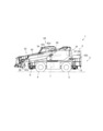
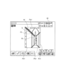
- a diagram showing a crane The figure which shows the structure of an image display system. The figure which shows the inside of a cabin. The figure which displayed the peripheral image and the bird's-eye view synthetic
- the working vehicle according to the first embodiment will be described using FIG.
- the work vehicle will be described as a mobile crane (hereinafter simply referred to as a crane), but the technical concept of the present application can also be applied to other work vehicles having the traveling body 2 .
- Another work vehicle is, for example, an aerial work vehicle.
- the crane 1 is mainly composed of a traveling body 2 and a revolving body 3.
- the traveling body 2 is provided with a pair of left and right front wheels 4 and rear wheels 5 respectively.
- the traveling body 2 is provided with an outrigger 6 that is grounded and stabilized when carrying out the work of transporting a load.
- the traveling body 2 can turn the rotating body 3 supported on the top thereof by a turning motor 7 .
- the revolving body 3 is equipped with a boom support 31.
- the revolving body 3 also has a boom 32 projecting forward from the rear portion of the boom support 31 .
- the boom 32 can be swiveled by the swivel motor 7 .
- the boom 32 is telescopically telescopic by means of a telescopic cylinder 34 .
- the boom 32 can be raised and lowered by a raising and lowering cylinder 35 .
- a wire rope 33 is stretched over the boom 32 .
- a hook 36 is attached to the wire rope 33 hanging down from the tip of the boom 32 .
- a winch 37 is installed near the base end of the boom 32 .
- the winch 37 is configured integrally with a winding hydraulic motor 38 to enable the wire rope 33 to be wound in and out. Therefore, the hook 36 can be moved up and down by the winding hydraulic motor 38 .
- the revolving body 3 has a cabin 39 on the side of the boom 32 .
- FIG. 1 the configuration of the image display system 41 provided in the crane 1 will be described using FIGS. 2 and 3.
- FIG. 2 the configuration of the image display system 41 provided in the crane 1 will be described using FIGS. 2 and 3.
- the image display system 41 has a camera 42, a control section 43, an image display section 48, and a buzzer 49.
- the camera 42 captures a peripheral image P of the running body 2 (see FIG. 4).
- the cameras 42 are composed of a front camera 42a, a rear camera 42b, a right camera 42c, and a left camera 42d.
- the installation position and number of the cameras 42 are not particularly limited as long as they can photograph the surroundings of the traveling body 2 .
- the front camera 42a captures, for example, the area in front of the traveling body 2 as a front image Pa including the horizon (see FIG. 4).
- the front camera 42a is provided at the front end portion of the traveling body 2 (the front end portion excluding the boom 32). Further, the front camera 42 a is connected to the control section 43 . Therefore, the control unit 43 can acquire the forward image Pa.
- the rear camera 42b captures, for example, the rear area including the rear end of the traveling body 2 as a rear image (not shown) including the horizon.
- the rear camera 42 b is provided at the rear end of the traveling body 2 .
- the rear camera 42 b is connected to the control section 43 . Therefore, the control unit 43 can acquire the rear image.
- the right camera 42c captures, for example, the right side area including the right end of the revolving body 3 as a right side image (not shown) including the horizon.
- the right camera 42c is provided at the right end portion of the revolving body 3 (the outer plate portion on the right side of the cabin 39). Also, the right camera 42 c is connected to the control unit 43 . Therefore, the control unit 43 can acquire the right image.
- the left camera 42d captures, for example, the left area including the left end of the revolving body 3 as a left image (not shown) including the horizon.
- the left camera 42d is provided at the left end portion of the revolving body 3 (the outer plate portion on the left side of the boom support 31). Also, the left camera 42 d is connected to the control unit 43 . Therefore, the control unit 43 can acquire the left image.
- the control unit 43 controls the display of the image display unit 48 and outputs warnings.
- the control unit 43 can process the acquired image. Further, the control unit 43 can switch the image displayed on the image display unit 48 according to the operation information of the operator.
- the control unit 43 has an overhead controller 44 , an image recognition controller 45 , a tracking controller 46 and a warning controller 47 .
- the control unit 43 is configured by a control circuit (not shown) exemplified by a processor such as a CPU (Central Processing Unit).
- the control unit 43 further has a storage unit (not shown) such as a memory that stores a predetermined program, and by causing the processor to execute the program, the overhead controller 44, the image recognition controller 45, and the tracking controller 46 are controlled. and each function of the warning controller 47 is realized.
- the bird's-eye view controller 44 synthesizes the surrounding images P to generate a bird's-eye composite image Pm of the surroundings of the traveling object 2 (see FIG. 4).
- the image recognition controller 45 detects the moving object photographed by the camera 42 on the image.
- a tracking controller 46 tracks the moving object on the image.
- the warning controller 47 warns that a moving body has entered the synthesizing section.
- the region that cannot be properly recognized is an example of a portion that is invisible or difficult for the operator to see in the image displayed on the image display section 48 .
- the mobile object is an object that moves around the crane 1, such as a person, a two-wheeled vehicle, a forklift, etc., and features such as shape are set in the image recognition controller 45 as objects to be detected.
- the moving object is detected as moving relative to crane 1 (camera 42). For example, even if the moving body is stationary, if the position or orientation of the camera 42 changes while the crane 1 is traveling or turning, the moving body is recognized as a moving body on the image by the image recognition controller 45. detected.
- the image display unit 48 displays images. As shown in FIG. 3, the image display unit 48 is provided inside the cabin 39 in front of the operator's seat so that the operator can visually recognize it while the crane 1 is running while looking forward.
- the image display unit 48 has a so-called touch panel, and operation information is input by the operator touching the display surface (touch operation).
- the image display unit 48 is connected to the control unit 43 . Therefore, the control unit 43 can cause the image display unit 48 to display images such as the surrounding image P and the bird's-eye composite image Pm (see FIG. 4). Further, the control unit 43 can acquire operation information input by the operator through the image display unit 48 .
- the operation information input by the operator is not limited to the touch operation, and may be input using an input device such as a button.
- the buzzer 49 vibrates a diaphragm to generate a buzzing sound.
- the buzzer 49 is attached inside the cabin 39 so that the operator can recognize the buzzer sound while the crane 1 is running.
- a buzzer 49 is connected to the control unit 43 . Therefore, the control unit 43 (warning controller 47) can transmit a signal to the buzzer 49 to cause the buzzer 49 to generate a buzzing sound.
- the bird's-eye composite image Pm is generally generated by first generating the bird's-eye view image of each peripheral image P, and converting it to positions corresponding to the front, rear, left, and right of the running body 2 (in the case where there are four cameras 42 as described above). It is generated by arranging each bird's-eye view image and performing a blending process to reduce the discomfort of the synthesizing unit S.
- this is only an example, and a method or the like may be used in which the four peripheral images P are directly converted into one panorama image, and the panorama image is converted into the bird's-eye composite image Pm.
- the bird's-eye composite image Pm may be arranged with a surrounding image P that has not been turned into a bird's-eye view image. That is, generation of the bird's-eye composite image Pm is not limited to converting the peripheral image P into a bird's-eye view image.
- the bird's-eye view controller 44 performs image processing so that the bird's-eye view images are seamlessly connected to generate the bird's-eye composite image Pm.
- the bird's-eye composite image Pm includes a front bird's-eye view image Pa1 obtained by converting the front image Pa into a bird's-eye image, a rear bird's-eye image Pb1 obtained by converting a rear image into a bird's-eye image, and a right image obtained by converting a right image into a bird's-eye image.
- the bird's-eye composite image Pm includes the front bird's-eye image Pa1 and the left bird's-eye image Pd1 up to the horizon, and has a wider display area than the rear bird's-eye image Pb1 and the right bird's-eye image Pc1.
- the bird's-eye view composite image Pm allows the entire circumference of the crane 1 to be visually recognized as a single image while the crane 1 is traveling forward. Suitable for
- a composite portion S which is a portion where the peripheral images P are joined together, is formed (light ink portion).
- the synthesizing unit S synthesizes images between the front bird's-eye image Pa1 and the right bird's-eye image Pc1, between the right bird's-eye image Pc1 and the rear bird's-eye image Pb1, between the rear bird's-eye image Pb1 and the left bird's-eye image Pd1, and the left bird's-eye image. They are respectively formed between the image Pd1 and the front bird's-eye view image Pa1.
- the synthesizing portion S may be a blind spot on the bird's-eye synthetic image Pm, or may be stretched during synthesis and displayed unnaturally. Therefore, there is a possibility that the operator will overlook the moving object existing in the synthesizing section S. Note that the area of the combining portion S in the bird's-eye combined image Pm is set in the control unit 43 .
- the crane 1 includes a shift switch (not shown) for detecting whether the crane 1 is in a state corresponding to forward travel or in a state corresponding to reverse travel, and a shift switch (not shown) for detecting whether the crane 1 is in a state corresponding to forward travel or reverse travel. and a PTO switch (not shown) for detecting whether or not the power source is being taken out by a PTO (Power take-off device).
- the shift switch and PTO switch are connected to the controller 43 . Therefore, the control unit 43 can recognize whether the crane 1 is traveling forward, whether the crane 1 is traveling backward, or whether the crane 1 is working.
- the control unit 43 changes the size of the display areas of the bird's-eye images Pa1, Pb1, Pc1, and Pd1 according to the conditions of forward traveling, backward traveling, and working, and selectively displays the bird's-eye composite image Pm. can be generated.
- the moving body M is described as a person, but it is not particularly limited, and the moving body M may be a two-wheeled vehicle, a forklift, or the like.
- the image recognition controller 45 detects a person on the bird's-eye synthetic image Pm using techniques such as deep learning. Specifically, the image recognition controller 45 extracts a person candidate based on the outline feature on the bird's-eye view composite image Pm, and uses a model that has learned the feature such as the shape of the person to recognize the above person. Determine whether the candidate is a person. As shown in FIG. 5, the control unit 43 superimposes and displays a rectangular frame F1 so as to surround the person on the bird's-eye composite image Pm as a detection result. The image recognition controller 45 holds the coordinate information of the area where the person exists on the bird's-eye composite image Pm.
- the area in which a person exists is an area surrounded by a minimum rectangular frame F1 (bounding box) capable of enclosing a person on the bird's-eye composite image Pm.
- the bird's-eye view composite image Pm is set to be updated at a cycle of 30 Hz, for example.
- the detection of the moving object M performed by the image recognition controller 45 is set to be performed every frame at a cycle of 30 Hz, for example, like the update of the bird's-eye composite image Pm.
- the method of detecting the moving body M is not particularly limited, and a known method can be used.
- the moving body M can be detected based on the feature amount of the moving body M. Further, when the position or orientation of the camera 42 is changed (when the crane 1 is traveling or turning), the movement of the moving body M is calculated based on the difference between the moving direction of the moving body M on the image and the moving direction of the background. Body M can be detected.
- the tracking controller 46 assigns an ID, which is identification information, to each detected moving object M. For example, on the bird's-eye view synthesized images Pm of continuous frames (on the bird's-eye view synthesized images Pm whose shooting time is continuous), if the areas within the bounding boxes overlap at a rate equal to or greater than a certain threshold, the same It is regarded as a moving body M and given a similar ID. As a result, the moving object M can be identified between consecutive frames, and the moving object M can be tracked.
- an ID which is identification information
- the tracking controller 46 considers that the moving object M is not the same and assigns a different ID. Give.
- the warning controller 47 highlights the combining section S when the moving body M enters the combining section S (when the moving body M becomes undetectable). For example, the warning controller 47 causes the image display unit 48 to display an elliptical frame F2 surrounding the composite portion S as a highlight display of the composite portion S.
- the warning controller 47 switches the display to the surrounding image P including the combining part S, and highlights the moving body M on the image display unit 48 .
- the warning controller 47 additionally displays the peripheral image P including the combined portion S, and causes the image display portion 48 to highlight the moving body M.
- FIG. 7 the warning controller 47 displays, as the switching display of the surrounding image P, the image of the forward image Pa in which the moving object M is captured. Then, the warning controller 47 causes the image display section 48 to display a frame F3 surrounding the moving object M as a highlight display of the synthesizing section S. As shown in FIG.
- the warning controller 47 displays, as an additional display of the peripheral image P, a bird's-eye synthetic image Pm and a front image Pa in which the moving object M is captured side by side. Then, the warning controller 47 causes the image display unit 48 to display a frame F4 surrounding the moving body M as a highlighted display of the moving body M. FIG. In addition, the warning controller 47 can display an elliptical frame F5 surrounding the synthesized portion S into which the moving object M has entered, thereby highlighting the synthesized portion S. FIG. As a result, the warning controller 47 can allow the operator to more accurately recognize the position of the moving object M that has entered the synthesizing section S.
- the warning controller 47 causes the buzzer 49 to generate a buzzing sound at the same time as the warning on the image display unit 48 described above. Thereby, the warning controller 47 can make the operator recognize that the moving body M has entered the synthesizing section S more reliably.
- the warning controller 47 continues the warning on the image display section 48 and the buzzer 49 for an arbitrary period of time. After that, the warning controller 47 returns the display of the image display unit 48 to the original bird's-eye synthetic image Pm, and stops the buzzer sound of the buzzer 49 .
- the operator can operate the crane 1 so that even if the moving body M enters the combining section S while the crane 1 is traveling, the moving body M and the traveling body 2 do not come into contact with each other.
- the image display system 41 detects the boom 32 and the suspended load on the bird's-eye composite image Pm during the work of the crane 1, and outputs a warning when the boom 32 and the load enter the synthesizing section S. You can also As a result, the operator can operate the boom 32 and the like so that the mobile object M does not come into contact with the boom 32 and the load.
- the work vehicle (crane 1) has an image recognition controller 45 that detects the moving body M photographed by the camera 42 on the image (overhead view composite image Pm), and the moving body M on the image (overhead view composite image Pm).
- a tracking controller 46 for tracking and a warning controller 47 for warning that the moving body M has entered the synthesizing section S are provided.
- the operator recognizes that the moving body M has entered the synthesizing section S. Therefore, the operator can use the overhead composite image Pm more safely.
- the camera 42 can be used as a sensor for detecting the moving object M, it is advantageous in terms of cost.
- the tracking controller 46 gives identification information (ID) to the mobile object M.
- ID identification information
- the tracking controller 46 gives identification information (ID) to the mobile object M.
- the image recognition controller 45 detects the mobile object M on the bird's-eye composite image Pm.
- the number of pixels of the bird's-eye composite image Pm is generally smaller than the total number of pixels of the peripheral images P. As shown in FIG. Therefore, the moving object M can be detected with fewer computational resources than when the peripheral image P is used.
- the warning controller 47 causes the image display unit 48 to highlight, when the moving body M has entered the combining part S, the combining part S into which the moving body M has entered.
- the position of the mobile object M that has entered the synthesizing section S can be recognized from the bird's-eye synthetic image Pm. Therefore, even if the moving object M enters the synthesizing section S, the operator can more safely drive or operate the work vehicle while grasping the position of the moving object M on the bird's-eye synthetic image Pm.
- the warning controller 47 switches the screen display to the surrounding image P and highlights the moving body M when the moving body M enters the synthesizing unit S. According to such a work vehicle, the position of the moving object M that has entered the synthesizing section S can be recognized from the peripheral image P. Therefore, even if the moving object M invades the synthesizing unit S, the operator can confirm the moving object M on the peripheral image P and safely drive or operate the work vehicle.
- the image recognition controller 45 detects a person on the peripheral image P using techniques such as deep learning. As shown in FIG. 9, in the peripheral image P, an area Sa corresponding to the combined portion S of the bird's-eye view combined image Pm is set (light ink portion). The area Sa is an example of a portion of the surrounding image P displayed on the image display unit 48 that is invisible or difficult for the operator to see.
- the warning controller 47 issues a warning using the image display unit 48 and the buzzer 49 when the moving object M has entered the area Sa.
- the warning controller 47 returns the display of the image display unit 48 to the original bird's-eye synthetic image Pm and stops the buzzer sound of the buzzer 49 when the moving object M cannot be detected in each peripheral image P.
- the image recognition controller 45 detects the mobile object M on the peripheral image P. According to such a work vehicle, the moving object M can be detected without relying on the bird's-eye composite image Pm.
- the technical idea of the present application can also be applied to the operation of arbitrarily arranging the peripheral images P from the respective cameras 42 and displaying them on the image display unit 48 without generating the bird's-eye composite image Pm.
- the image recognition controller 45 can perform moving object detection processing on the surrounding images P from each camera 42 .
- the image recognition controller 45 performs moving object detection processing not only on the peripheral image P being displayed on the image display unit 48, but also on (data of) the peripheral image P not displayed on the image display unit 48. It can be carried out.
- the peripheral image P not displayed on the image display unit 48 is an example of a portion of the peripheral image P being displayed on the image display unit 48 that is invisible or difficult for the operator to see.
- the warning controller 47 displays the position of the moving object M with respect to the traveling object 2 as visual information (for example, the moving object M).
- the warning can be given by switching the screen display to the surrounding image P where is detected and highlighting the moving object M) or by audio information (for example, outputting the direction in which the moving object M is detected by audio).
Landscapes
- Engineering & Computer Science (AREA)
- Multimedia (AREA)
- Mechanical Engineering (AREA)
- Signal Processing (AREA)
- Closed-Circuit Television Systems (AREA)
Priority Applications (1)
| Application Number | Priority Date | Filing Date | Title |
|---|---|---|---|
| JP2023546897A JPWO2023037936A1 (https=) | 2021-09-08 | 2022-08-30 |
Applications Claiming Priority (2)
| Application Number | Priority Date | Filing Date | Title |
|---|---|---|---|
| JP2021146434 | 2021-09-08 | ||
| JP2021-146434 | 2021-09-08 |
Publications (1)
| Publication Number | Publication Date |
|---|---|
| WO2023037936A1 true WO2023037936A1 (ja) | 2023-03-16 |
Family
ID=85506690
Family Applications (1)
| Application Number | Title | Priority Date | Filing Date |
|---|---|---|---|
| PCT/JP2022/032652 Ceased WO2023037936A1 (ja) | 2021-09-08 | 2022-08-30 | 作業車両 |
Country Status (2)
| Country | Link |
|---|---|
| JP (1) | JPWO2023037936A1 (https=) |
| WO (1) | WO2023037936A1 (https=) |
Cited By (1)
| Publication number | Priority date | Publication date | Assignee | Title |
|---|---|---|---|---|
| JP7853393B1 (ja) | 2024-12-10 | 2026-04-28 | 日立建機株式会社 | 作業機械の映像表示システム |
Citations (6)
| Publication number | Priority date | Publication date | Assignee | Title |
|---|---|---|---|---|
| JP2002019556A (ja) * | 2000-07-04 | 2002-01-23 | Matsushita Electric Ind Co Ltd | 監視システム |
| JP2003169323A (ja) * | 2001-11-29 | 2003-06-13 | Clarion Co Ltd | 車両周囲監視装置 |
| JP2006131166A (ja) * | 2004-11-09 | 2006-05-25 | Alpine Electronics Inc | 運転支援装置 |
| JP2014064144A (ja) * | 2012-09-20 | 2014-04-10 | Komatsu Ltd | 作業車両用周辺監視システム及び作業車両 |
| JP2016119559A (ja) * | 2014-12-19 | 2016-06-30 | 日立建機株式会社 | 作業機械の周囲監視装置 |
| JP2018148386A (ja) * | 2017-03-06 | 2018-09-20 | 日立建機株式会社 | 移動物体検知システム |
-
2022
- 2022-08-30 WO PCT/JP2022/032652 patent/WO2023037936A1/ja not_active Ceased
- 2022-08-30 JP JP2023546897A patent/JPWO2023037936A1/ja active Pending
Patent Citations (6)
| Publication number | Priority date | Publication date | Assignee | Title |
|---|---|---|---|---|
| JP2002019556A (ja) * | 2000-07-04 | 2002-01-23 | Matsushita Electric Ind Co Ltd | 監視システム |
| JP2003169323A (ja) * | 2001-11-29 | 2003-06-13 | Clarion Co Ltd | 車両周囲監視装置 |
| JP2006131166A (ja) * | 2004-11-09 | 2006-05-25 | Alpine Electronics Inc | 運転支援装置 |
| JP2014064144A (ja) * | 2012-09-20 | 2014-04-10 | Komatsu Ltd | 作業車両用周辺監視システム及び作業車両 |
| JP2016119559A (ja) * | 2014-12-19 | 2016-06-30 | 日立建機株式会社 | 作業機械の周囲監視装置 |
| JP2018148386A (ja) * | 2017-03-06 | 2018-09-20 | 日立建機株式会社 | 移動物体検知システム |
Cited By (1)
| Publication number | Priority date | Publication date | Assignee | Title |
|---|---|---|---|---|
| JP7853393B1 (ja) | 2024-12-10 | 2026-04-28 | 日立建機株式会社 | 作業機械の映像表示システム |
Also Published As
| Publication number | Publication date |
|---|---|
| JPWO2023037936A1 (https=) | 2023-03-16 |
Similar Documents
| Publication | Publication Date | Title |
|---|---|---|
| US10661712B2 (en) | Bird's-eye view image system, bird's-eye view image display method and program | |
| JP5529943B2 (ja) | 作業車両用周辺監視システム及び作業車両 | |
| JP5128566B2 (ja) | 周囲画像提示装置及び操作支援システム | |
| EP3595298B1 (en) | Human detection system for work vehicle, and work vehicle equipped with same | |
| JP6352797B2 (ja) | 作業機械の周囲監視装置 | |
| JP6017691B2 (ja) | 情報提示装置、クレーンシステム及び情報提示方法 | |
| JP2011035729A (ja) | 車両周辺画像表示装置および車両周辺画像表示方法 | |
| WO2019208283A1 (ja) | クレーン車 | |
| JP2010112100A (ja) | 作業機械の監視装置 | |
| JP6507501B2 (ja) | クレーン車の障害物報知システム | |
| JP2002176641A (ja) | 周囲映像提示装置 | |
| JP2010165087A (ja) | 運転支援装置 | |
| WO2017038123A1 (ja) | 車両の周囲監視装置 | |
| JP6917167B2 (ja) | 建設機械用俯瞰画像表示装置 | |
| JP5926315B2 (ja) | 作業車両用周辺監視システム及び作業車両 | |
| JP5718080B2 (ja) | 車両用周辺監視装置 | |
| WO2023037936A1 (ja) | 作業車両 | |
| JP6756554B2 (ja) | 画像表示システム | |
| JP2003063339A (ja) | 駐車支援装置 | |
| JP2019087909A (ja) | 画像表示装置、及び画像表示システム | |
| JP2016013888A (ja) | クレーン車の障害物報知システム | |
| JP2018039476A (ja) | 画像表示システム | |
| JP2017061283A (ja) | 作業車両の周囲監視装置 | |
| US12030751B2 (en) | Crane information display system | |
| JP2016013890A (ja) | クレーン車の障害物報知システム |
Legal Events
| Date | Code | Title | Description |
|---|---|---|---|
| 121 | Ep: the epo has been informed by wipo that ep was designated in this application |
Ref document number: 22867258 Country of ref document: EP Kind code of ref document: A1 |
|
| WWE | Wipo information: entry into national phase |
Ref document number: 2023546897 Country of ref document: JP |
|
| NENP | Non-entry into the national phase |
Ref country code: DE |
|
| 122 | Ep: pct application non-entry in european phase |
Ref document number: 22867258 Country of ref document: EP Kind code of ref document: A1 |