WO2023032642A1 - 回転電機 - Google Patents
回転電機 Download PDFInfo
- Publication number
- WO2023032642A1 WO2023032642A1 PCT/JP2022/030779 JP2022030779W WO2023032642A1 WO 2023032642 A1 WO2023032642 A1 WO 2023032642A1 JP 2022030779 W JP2022030779 W JP 2022030779W WO 2023032642 A1 WO2023032642 A1 WO 2023032642A1
- Authority
- WO
- WIPO (PCT)
- Prior art keywords
- armature
- position regulating
- regulating member
- winding
- partial
- Prior art date
Links
- 238000004804 winding Methods 0.000 claims abstract description 439
- 230000001105 regulatory effect Effects 0.000 claims description 310
- 230000007704 transition Effects 0.000 claims description 186
- 229920005989 resin Polymers 0.000 claims description 90
- 239000011347 resin Substances 0.000 claims description 90
- 239000004020 conductor Substances 0.000 claims description 71
- 239000000463 material Substances 0.000 claims description 49
- 239000011810 insulating material Substances 0.000 claims description 30
- 238000000465 moulding Methods 0.000 claims description 11
- 238000001514 detection method Methods 0.000 claims description 10
- 238000009413 insulation Methods 0.000 description 19
- 239000002826 coolant Substances 0.000 description 11
- 230000033228 biological regulation Effects 0.000 description 10
- 230000000149 penetrating effect Effects 0.000 description 10
- 230000002093 peripheral effect Effects 0.000 description 9
- 238000000034 method Methods 0.000 description 8
- 229910052751 metal Inorganic materials 0.000 description 7
- 239000002184 metal Substances 0.000 description 7
- 229910001018 Cast iron Inorganic materials 0.000 description 6
- 229910052782 aluminium Inorganic materials 0.000 description 6
- XAGFODPZIPBFFR-UHFFFAOYSA-N aluminium Chemical compound [Al] XAGFODPZIPBFFR-UHFFFAOYSA-N 0.000 description 6
- 230000006866 deterioration Effects 0.000 description 6
- 230000017525 heat dissipation Effects 0.000 description 6
- 230000008569 process Effects 0.000 description 6
- 238000010586 diagram Methods 0.000 description 5
- 238000004519 manufacturing process Methods 0.000 description 5
- 238000000926 separation method Methods 0.000 description 5
- 229910000838 Al alloy Inorganic materials 0.000 description 4
- 239000004918 carbon fiber reinforced polymer Substances 0.000 description 4
- 238000001816 cooling Methods 0.000 description 4
- 238000003780 insertion Methods 0.000 description 4
- 230000037431 insertion Effects 0.000 description 4
- 230000005415 magnetization Effects 0.000 description 4
- 239000011295 pitch Substances 0.000 description 4
- 239000000853 adhesive Substances 0.000 description 3
- 230000001070 adhesive effect Effects 0.000 description 3
- 238000005452 bending Methods 0.000 description 3
- 230000000694 effects Effects 0.000 description 3
- 230000004907 flux Effects 0.000 description 3
- 230000001771 impaired effect Effects 0.000 description 3
- 230000015572 biosynthetic process Effects 0.000 description 2
- 230000008859 change Effects 0.000 description 2
- 239000000498 cooling water Substances 0.000 description 2
- 238000013461 design Methods 0.000 description 2
- 239000000696 magnetic material Substances 0.000 description 2
- 238000012986 modification Methods 0.000 description 2
- 230000004048 modification Effects 0.000 description 2
- 239000003507 refrigerant Substances 0.000 description 2
- 230000000452 restraining effect Effects 0.000 description 2
- 229920003002 synthetic resin Polymers 0.000 description 2
- 239000000057 synthetic resin Substances 0.000 description 2
- 238000012546 transfer Methods 0.000 description 2
- 229910000831 Steel Inorganic materials 0.000 description 1
- 239000003990 capacitor Substances 0.000 description 1
- 239000000470 constituent Substances 0.000 description 1
- 230000002708 enhancing effect Effects 0.000 description 1
- 238000007654 immersion Methods 0.000 description 1
- 230000002452 interceptive effect Effects 0.000 description 1
- 238000010030 laminating Methods 0.000 description 1
- 239000010687 lubricating oil Substances 0.000 description 1
- 229910001172 neodymium magnet Inorganic materials 0.000 description 1
- 230000007935 neutral effect Effects 0.000 description 1
- NJPPVKZQTLUDBO-UHFFFAOYSA-N novaluron Chemical compound C1=C(Cl)C(OC(F)(F)C(OC(F)(F)F)F)=CC=C1NC(=O)NC(=O)C1=C(F)C=CC=C1F NJPPVKZQTLUDBO-UHFFFAOYSA-N 0.000 description 1
- 239000003921 oil Substances 0.000 description 1
- 230000001737 promoting effect Effects 0.000 description 1
- 230000004044 response Effects 0.000 description 1
- 239000004065 semiconductor Substances 0.000 description 1
- 239000010959 steel Substances 0.000 description 1
Images


Classifications
-
- H—ELECTRICITY
- H02—GENERATION; CONVERSION OR DISTRIBUTION OF ELECTRIC POWER
- H02K—DYNAMO-ELECTRIC MACHINES
- H02K3/00—Details of windings
- H02K3/46—Fastening of windings on the stator or rotor structure
- H02K3/47—Air-gap windings, i.e. iron-free windings
Definitions
- the disclosure in this specification relates to a rotating electric machine.
- a rotating electric machine that includes a field element including a magnet portion having a plurality of magnetic poles whose polarities alternate in the circumferential direction, and an armature having multiphase armature windings. Armatures having a toothless structure are also known.
- the winding regulating member is made of metal from the viewpoint of rigidity.
- the insulation of the armature winding may be impaired.
- the present disclosure has been made in view of the above circumstances, and aims to provide a rotating electric machine that can properly maintain the insulation state of the armature winding.
- Means 1 is A rotating electric machine comprising a field magnet having a plurality of magnetic poles, an armature having a toothless structure having multi-phase armature windings, and an armature holding member holding the armature, the armature winding has a phase winding composed of a plurality of partial windings for each phase;
- the partial winding has a pair of intermediate conductor portions provided at a predetermined interval in the circumferential direction, and transition portions provided at one end side and the other end side in the axial direction and annularly connecting the pair of intermediate conductor portions.
- the partial winding is assembled to the armature holding member by a position regulating member that is a part of the armature holding member or a member fixed to the armature holding member.
- the position of is regulated,
- An insulating layer is interposed between the partial winding and the position regulating member.
- a rotating electrical machine with a toothless armature requires a structure to fix the armature windings.
- an armature holding member is used to hold the armature, and the positions of the partial windings constituting the armature winding are controlled by a part of the armature holding member or a member fixed to the armature holding member. Appropriate fixation of the armature winding can be achieved by regulating it with the member.
- a metal position regulating member is used from the viewpoint of rigidity, there is a concern that the insulation of the armature winding will be impaired due to contact between the partial windings and the position regulating member. With respect to this concern, the insulating layer is interposed between the partial winding and the position regulating member, so that the deterioration of the insulation can be suppressed. As a result, the insulated state of the armature winding can be properly maintained.
- the position regulating member is provided in a state of being inserted into the annular inner side of the transition portion at the coil end, and the position regulating member is positioned between the transition portion and the position regulating member.
- An insulating layer is interposed.
- the position regulating member in a state of being inserted into the annular inner side of the transition portion at the coil end of the armature, it is possible to regulate the position of each partial winding in two different directions. For example, in a configuration in which the transition portion extends in the axial direction (a configuration in which the transition portion is not bent in the radial direction), the position regulating member is inserted into the annular inner side of the transition portion, thereby restricting the position in the circumferential and axial directions. becomes possible. In addition, in the configuration in which the transition portion is bent and extends in the radial direction, the position restriction member is inserted into the annular inner side of the transition portion, so that position restriction in the circumferential direction and the radial direction is possible. Further, since the insulating layer is interposed between the transition portion and the position regulating member, it is possible to suppress deterioration of the insulation of the partial winding due to the position regulating member.
- the partial winding is formed in an annular shape by winding the conductive wire material multiple times on the basis of the inner circumference side.
- the tolerance of the partial winding when designing the separation distance (insulation distance) between the transition portion and the position regulating member. It's becoming
- the armature winding has, as the partial windings, a first partial winding and a second partial winding in which the shapes of the transition portions at the coil ends are different, At least one of the first partial winding and the second partial winding is bent in the radial direction at the coil end and is arranged to overlap each other in the circumferential direction, and the position regulating member comprises: It is provided as a common member that regulates the respective positions of the first partial winding and the second partial winding.
- each position of the first partial winding and the second partial winding is configured to be positionally regulated using a common position regulating member, so that the number of parts can be reduced and the configuration can be simplified.
- the position regulating member as the common member comprises a portion on the annular inner side of the transition portion of the first partial winding and an annular inner portion of the transition portion on the second partial winding. It is provided in a state in which it enters each of the parts to be.
- each transition portion is arranged close to each other.
- the position regulating member is provided so as to be inserted into the annular inner portion of the transition portion of the first partial winding and the annular inner portion of the transition portion of the second partial winding. bottom. This makes it possible to easily achieve positional regulation in a plurality of directions for each partial winding.
- the position regulating member is a member provided separately from the armature holding member and fixed to the armature holding member by a fixture.
- the position regulating member enters a portion of the first partial winding that is annularly inside the transition portion, while facing the transition portion of the second partial winding from the outside in the axial direction. is provided.
- the position regulating member can be assembled while taking into account the bent state of the connecting portion of each partial winding.
- the position regulating member is a member provided separately from the armature holding member and fixed to the armature holding member by a fixture, and the coil end: In the first partial winding, the transition portion is bent in the radial direction, and in the second partial winding, the transition portion is not bent in the radial direction, and the position regulating member as the common member comprises: It is provided in a state in which it enters a portion of the first partial winding that is the annular inner side of the transition portion, while facing a portion of the second partial winding that is the annular outer portion of the transition portion. .
- the position regulating member which is a common member, is set in a state of being inserted into the annular inner portion of the transition portion of the first partial winding, while being opposed to the annular outer portion of the transition portion of the second partial winding. It was configured to In this case, the position regulating member can be assembled while taking into account the bent state of the connecting portion of each partial winding. In addition, after the first partial winding and the second partial winding are assembled, the position regulating member can be axially assembled, thereby facilitating the manufacturing work.
- the position regulating member has a portion that sandwiches the circumferentially extending portion of the transition portion of the second partial winding from each of the annular outer side and the annular inner side.
- the second partial winding is a partial winding having a crossover portion that is not bent in the radial direction at any of the coil ends, and the circumferentially extending portion of the crossover portion of the second partial winding is a position regulating member. It was configured to be sandwiched from each of the annular outer side and the annular inner side. In this case, since the transition portion of the second partial winding is sandwiched from both sides in the axial direction by the position regulating members, it is possible to appropriately regulate the position in the axial direction.
- the position regulating member is a member provided separately from the armature holding member and fixed to the armature holding member by a fixture, It has an annular portion, and a restricting portion is provided on either the inner or outer side in the radial direction of the annular portion so as to enter the annular inner side of the transition portion of the partial winding.
- a fixed portion fixed to the armature holding member by the fixture is provided on the side.
- a regulating portion that enters the annular inner side of the transition portion of the partial winding is provided on either the radially inner or outer side of the annular portion.
- a fixed portion which is fixed to the armature holding member by a fixture, is provided on the other side.
- a regulating portion for regulating the position of the partial winding and a fixed portion mechanically fixed to the armature holding member are provided at radially inner and outer positions of the position regulating member. Therefore, the position regulating member can be fixed to the armature holding member without interfering with the position regulation of the connecting portions arranged in the circumferential direction.
- the restricting portion can be provided with sufficient strength.
- Means 9 in any one of Means 1 to 8, the transition portions of the plurality of partial windings are arranged in the circumferential direction, and the annular position regulating member faces the transition portions arranged in the circumferential direction. is provided, and a wiring module electrically connected to each of the partial windings forms a loop and is provided in a state of being fixed to the position regulating member.
- an annular position regulating member is provided so as to face each of the transition portions lined up in the circumferential direction, and the annular wiring module is fixed to the position regulating member. It was configured to As a result, it is possible to suitably realize electrical connection between each partial winding arranged in the circumferential direction and the wiring module while reducing the number of parts.
- any one of means 1 to 9 at least one of the coil ends on both sides in the axial direction, these members are integrated within a range including the transition portion of the partial winding and the position regulating member.
- the insulating layer is formed by resin molding.
- At least one of the coil ends in the axial direction is integrally resin-molded in a range including the transition portion of the partial winding and the position regulating member, thereby separating the transition portion of the partial winding and the position regulating member.
- the resin molded portion is formed using the same resin material within the range including.
- the insulating layer can be appropriately formed in the portion facing the position regulating member around the transition portion of the partial winding (the gap portion between the transition portion and the position regulating member).
- the annular portion of the position regulating member is provided with a through hole penetrating in the axial direction, and the range including the inside of the through hole and both sides of the annular portion in the axial direction is provided. It is resin molded.
- the annular portion of the position regulating member is provided with a through hole penetrating in the axial direction, thereby promoting the flow of the resin material from the axially outer side to the axially inner side of the position regulating member.
- the resin material is reliably made to flow between the transition portions of the partial windings and the position regulating member, and proper formation of the resin molded portion (formation of the insulating layer) can be achieved.
- the portion of the position regulating member that is on the opposite side of the armature holding member across the transition portion and that surrounds the transition portion is a non-resin-molded portion. It is a mold part.
- the portion that is on the opposite side of the armature holding member across the transition portion and that surrounds the transition portion is defined as a non-molded portion that is not molded with resin.
- a part of the position regulating member is exposed to the outside without being molded with resin, thereby improving heat dissipation.
- the non-molded portion (exposed portion) of the position regulating member serves as an oil-cooled heat radiating portion.
- the armature holding member is provided with the position regulating member on one axial end side and the other axial end side, respectively, and the position regulating member on the axial one end side in the axial direction
- a component that extends from the position regulating member to the position regulating member on the other axial end side and includes the intermediate conductor portion of the partial winding is molded with resin.
- the constituent members including the respective position regulating members on both ends in the axial direction and the intermediate conductor portions of the partial windings are resin-molded.
- the resin mold is formed in a range that includes the entire partial winding, and unintended insulation deterioration in the partial winding can be appropriately suppressed.
- the armature has an armature core provided radially inside or outside the armature winding, and the intermediate conductor portion of the partial winding and the armature core, and the insulating material is a resin material having higher adhesion than the insulating layer at the coil end.
- the insulating material interposed between the intermediate conductors of the partial windings and the armature core is made of a resin material with higher adhesive strength than the insulating layer at the coil ends, so the assembly strength of the partial windings to the armature core is increased. can be increased, and positional deviation of the partial windings can be suitably suppressed.
- the armature has an armature core provided radially inside or outside the armature winding, and the intermediate conductor portion of the partial winding and the armature core, and the insulating material is a resin material having a higher thermal conductivity than the insulating layer at the coil end.
- the insulating material interposed between the intermediate conductor part of the partial winding and the armature core is made of a resin material with a higher thermal conductivity than the insulating layer at the coil end, so that the cooling performance of the intermediate conductor part is improved. be able to.
- a temperature detection section for detecting the temperature of the armature is provided, and the temperature detection section is resin-molded together with the transition section and the position regulating member.
- the resin-molded part can both transfer heat to the temperature detection part and fix the temperature detection part.
- the first coil end on one side in the axial direction is provided as the position regulating member, which is a member separate from the armature holding member and is related to the armature holding member.
- a first position regulating member fixed to the armature holding member by a fixture is provided, and a second position regulating member is provided on the second coil end on the other side in the axial direction as the position regulating member in a state of protruding in the radial direction.
- a member is integrally formed with the armature holding member.
- a first position regulating member which is a separate member from the armature holding member, is fixed by a fixture to a first coil end on one axial end side of the armature holding member, and a second coil end on the other axial end side of the armature holding member is fixed with a fixture.
- the configuration is such that the second position regulating member is integrally formed in a radially protruding state. According to this configuration, when the partial windings are assembled to the armature holding member, the partial windings are first assembled while being positionally regulated by the second position regulating member integrally formed with the armature holding member. After that, the first position restricting member can be retrofitted to the assembly including the armature holding member and the partial winding.
- the armature winding includes, as the partial windings, a partial winding having the transition portion that is radially bent at the second coil end, and a partial winding that is not radially bent.
- the second position regulating member has an annular wall portion radially opposed to the cylindrical portion of the armature holding member; The bridge portion, which is not bent in the radial direction, is inserted into an annular groove formed between the portion and the annular wall portion.
- a second position regulating member that protrudes radially in the armature holding member is provided with an annular wall portion, and an annular groove portion is formed between the cylindrical portion and the annular wall portion of the armature holding member.
- a connecting portion that is not bent in the radial direction is inserted. In this case, by inserting the transition portion into the annular groove, it becomes possible to regulate the position of the partial winding having the transition portion in the radial direction and the axial direction.
- the annular wall portion has a plurality of regulating portions provided at predetermined intervals in the circumferential direction and extending in the axial direction;
- the restricting portion is in a state of being inserted into the annular inner side of the radially bent transition portion.
- the annular wall portion of the second position regulating member is provided with a plurality of regulating portions extending in the axial direction at predetermined intervals in the circumferential direction, and the regulating portions enter the annular inner side of the transition portion bent in the radial direction. .
- the restricting portion of the annular wall portion since the restricting portion of the annular wall portion enters the annular inner side of the transition portion, it is possible to restrict the position of the partial winding having the transition portion in the circumferential direction.
- the armature has an armature core provided radially inside or outside the armature winding, and the armature core comprises the armature An insulating material forming the insulating layer is interposed between the armature core and the armature holding member so as to face the holding member in the radial direction.
- the gap between the armature core and the armature holding member is used as a passage for the insulating material (resin material) to flow. can be easily formed (resin mold).
- Passages are formed between the armature core and the armature holding member so as to extend in the axial direction at predetermined intervals in the circumferential direction and to allow the flow of insulating material during manufacture of the armature. Good.
- the armature has an armature core provided radially inside or outside the armature winding, and the position regulating member comprises the armature
- the armature core and the position regulating member which are provided separately from the holding member, are provided with through holes penetrating in the axial direction. are overlapped, a fixture is inserted through each of the through holes of the armature core and the position regulating member, and the fixture is fastened on the opposite side of the position regulating member with the armature core sandwiched therebetween.
- the fixture With the position regulating member superimposed on the axial end face of the armature core, the fixture is inserted through each through hole of the armature core and the position regulating member, and the fixture is inserted into the position regulating member with the armature core sandwiched therebetween. It was configured to be fastened on the opposite side of the As a result, it is possible to fix the armature core and the position regulating member at the same time.
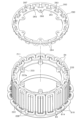
- FIG. 1 is a vertical cross-sectional view of a rotating electric machine in the first embodiment
- FIG. 2 is a perspective view showing the appearance of the stator unit
- FIG. 3 is a plan view of the stator unit
- 4, (a) is a cross-sectional view along the line 4a-4a in FIG. 3
- (b) is a cross-sectional view along the line 4b-4b in FIG.
- FIG. 5 is an exploded perspective view of the core assembly
- 6, (a) is a vertical cross-sectional view of the core assembly
- (b) is a cross-sectional view of the core assembly
- FIG. 1 is a vertical cross-sectional view of a rotating electric machine in the first embodiment
- FIG. 2 is a perspective view showing the appearance of the stator unit
- FIG. 3 is a plan view of the stator unit
- 4 is a cross-sectional view along the line 4a-4a in FIG. 3
- (b) is a cross-sectional view along the line 4b-4b
- FIG. 7 is a perspective view of a position regulating member;
- FIG. 8 is a perspective view showing a state in which the position regulating member is attached to the core assembly;
- FIG. 9 is a perspective view showing the configuration of the partial winding,
- FIG. 10 is a perspective view showing the configuration of the position regulating member;
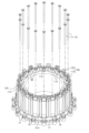
- FIG. 11 is a vertical cross-sectional view of the stator unit,
- FIG. 12 is a perspective view of the wiring module,
- FIG. 13 is an exploded perspective view of the stator unit;
- FIG. 14 is a perspective view for explaining the assembly process of the stator unit;
- FIG. 15 is a perspective view for explaining the assembly process of the stator unit;
- FIG. 16 is a perspective view for explaining the assembly process of the stator unit;
- FIG. 17 is a perspective view for explaining the assembly process of the stator unit;
- FIG. 18 is a longitudinal sectional view of the stator unit,
- FIG. 19 is a perspective view showing the appearance of the stator unit in the second embodiment,
- FIG. 20 is a plan view of the stator unit, 21, (a) is a cross-sectional view taken along line 21a-21a in FIG. 20, and (b) is a cross-sectional view taken along line 21b-21b in FIG.
- FIG. 22 is an exploded perspective view showing the core assembly and the position regulating member;
- FIG. 23 is a longitudinal sectional view of the stator unit,
- FIG. 24 is a perspective view showing the appearance of the stator unit in the third embodiment,
- FIG. 25 is a longitudinal sectional view of the stator unit, FIG.
- FIG. 26 is an exploded perspective view of the stator unit;
- FIG. 27 is an exploded perspective view of the stator unit;
- FIG. 28 is a perspective view showing the appearance of the stator unit in the fourth embodiment;
- FIG. 29 is a perspective view showing a state in which the position regulating member is separated in the stator unit;
- FIG. 30 is a perspective view showing the appearance of the stator unit in the fifth embodiment;
- FIG. 31 is a perspective view showing a state in which the position regulating member is separated in the stator unit;
- FIG. 32 is a diagram showing partial windings of a modified example.
- the rotary electric machine in this embodiment is used as a vehicle power source, for example.
- the rotating electric machine can be widely used for industrial use, vehicle use, aircraft use, home appliance use, OA equipment use, game machine use, and the like.
- parts that are the same or equivalent to each other are denoted by the same reference numerals in the drawings, and the description of the same reference numerals is used.
- the rotary electric machine 10 is an outer rotor type surface magnet type polyphase AC motor, and is used as an in-wheel motor of a vehicle.
- FIG. 1 is a vertical cross-sectional view of a rotating electrical machine 10.
- the direction in which the rotation axis extends is defined as the axial direction
- the direction radially extending from the center of the rotation axis is defined as the radial direction
- the direction extending circumferentially about the rotation axis is defined as the circumferential direction.
- the rotary electric machine 10 is roughly divided into a rotary electric machine main body having a rotor 20 and a stator unit 30 including a stator 40.
- the rotary electric machine main body is fixed to a vehicle body (not shown).
- a substantially cylindrical spindle 11 and a hub 12 fixed to a wheel (not shown) are integrated.
- the hub 12 has an insertion hole 13 through which the spindle 11 is inserted.
- the hub 12 is rotatably supported by a pair of bearings 14 and 15 while the spindle 11 is inserted through the insertion hole 13 of the hub 12 .
- the direction in which the axis serving as the center of rotation extends (horizontal direction in FIG. 1) is the axial direction, and the rotary electric machine 10 is installed in the vehicle so that the axial direction is horizontal or substantially horizontal. It's becoming
- the rotor 20 and the stator 40 are arranged to face each other in the radial direction with an air gap therebetween.
- a stator unit 30 is fixed to the spindle 11 and a rotor 20 is fixed to the hub 12 . Therefore, the hub 12 and rotor 20 are rotatable with respect to the spindle 11 and stator unit 30 .
- the rotor 20 corresponds to the "field element" and the stator 40 corresponds to the "armature".
- the rotor In a state in which the integrated body of the spindle 11 and the stator unit 30 and the integrated body of the hub 12 and the rotor 20 are assembled with each other, the rotor is provided on one axial end side of the rotor 20 (base end side of the spindle 11).
- a cover 16 is fixed.
- the rotor cover 16 has an annular plate shape, and is fixed to the rotor 20 with fasteners such as bolts with the bearing 17 interposed between the rotor cover 16 and the stator unit 30 .
- the rotor 20 has a substantially cylindrical rotor carrier 21 and an annular magnet unit 22 fixed to the rotor carrier 21 .
- the rotor carrier 21 has a tubular portion 23 having a cylindrical shape and an end plate portion 24 provided on one axial end side of the tubular portion 23 .
- a magnet unit 22 is fixed annularly.
- the other axial end of the rotor carrier 21 is open.
- the rotor carrier 21 functions as a magnet holding member.
- a through hole 24a is formed in the central portion of the end plate portion 24, and the hub 12 is fixed to the end plate portion 24 by a fastener such as a bolt while being inserted through the through hole 24a.
- the magnet unit 22 is composed of a plurality of permanent magnets arranged so that their polarities alternate along the circumferential direction of the rotor 20 . Thereby, the magnet unit 22 has a plurality of magnetic poles in the circumferential direction.
- the magnet unit 22 corresponds to the "magnet section".
- the permanent magnet is, for example, a sintered neodymium magnet having an intrinsic coercive force of 400 [kA/m] or more and a residual magnetic flux density Br of 1.0 [T] or more.
- the magnet unit 22 has a plurality of polar anisotropic permanent magnets, and each magnet is magnetized on the d-axis side (portion near the d-axis) and the q-axis side (portion near the q-axis).
- the orientation of the easy axis is different, the orientation of the easy axis of magnetization is parallel to the d-axis on the d-axis side, and the orientation of the easy axis of magnetization is perpendicular to the q-axis on the q-axis side.
- an arcuate magnet magnetic path is formed along the direction of the axis of easy magnetization.
- each magnet is oriented such that the direction of the axis of easy magnetization is parallel to the d-axis on the d-axis side, which is the magnetic pole center, compared to the q-axis side, which is the magnetic pole boundary.
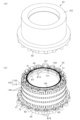
- FIG. 2(a) and 2(b) are perspective views showing the appearance of the stator unit 30, of which FIG. 2(b) shows a state where the resin mold provided in the stator unit 30 is removed.
- . 3 is a plan view of the stator unit 30,
- FIG. 4(a) is a sectional view taken along line 4a-4a in FIG. 3
- FIG. 4(b) is a sectional view taken along line 4b-4b in FIG. be.
- the stator unit 30 generally includes a stator 40, a radially inner stator holder 50, and a wiring module 130.
- the stator 40 has a toothless structure and has a stator winding 41 and a stator core 42 .
- the stator core 42 and the stator holder 50 are integrally provided as a core assembly CA, and a plurality of partial windings 81 constituting the stator winding 41 are assembled to the core assembly CA.
- the stator winding 41 corresponds to the "armature winding”
- the stator core 42 corresponds to the "armature core”
- the stator holder 50 corresponds to the "armature holding member”.
- the core assembly CA corresponds to the "supporting member”.
- a range including the stator 40 and the wiring module 130 of the stator unit 30 is covered with a resin material. Therefore, the stator unit 30 is covered with the resin mold portion 150 except for a part thereof, and its outer peripheral surface is formed to be a resin surface (see FIG. 2(a)).
- FIG. 5 is an exploded perspective view of the core assembly CA
- FIG. 6(a) is a longitudinal sectional view of the core assembly CA
- FIG. 6(b) is a lateral sectional view of the core assembly CA (FIG. 6 ( 6b-6b line sectional view of a)).
- the core assembly CA has the stator core 42 and the stator holder 50 assembled radially inward thereof.
- the stator core 42 is integrally attached to the outer peripheral surface of the stator holder 50 .
- the stator core 42 is configured as a core sheet laminate in which core sheets made of magnetic steel sheets, which are magnetic materials, are laminated in the axial direction, and has a cylindrical shape with a predetermined thickness in the radial direction.
- the radially outer peripheral surface of the stator core 42 is curved without irregularities, and the stator windings 41 are assembled to the outer peripheral surface (that is, the rotor 20 side of the radially inner and outer surfaces).
- the stator core 42 functions as a back yoke.
- the stator core 42 is configured by laminating a plurality of core sheets, which are punched into, for example, an annular plate shape, in the axial direction.
- a stator core 42 having a helical core structure may be used. In the stator core 42 of the helical core structure, a band-shaped core sheet is used, and this core sheet is wound in an annular shape and laminated in the axial direction, thereby forming a cylindrical stator core 42 as a whole. It is
- a plurality of protrusions 43 are provided at predetermined intervals in the circumferential direction on the inner peripheral surface on the radially inner side.
- the protrusions 43 are portions that locally increase the radial thickness of the stator core 42 , and the portions thickened by the protrusions 43 are formed with through holes 44 penetrating in the axial direction.
- the stator 40 has a slotless structure that does not have teeth for forming slots. can be anything. These (A) to (C) substantially correspond to the toothless structure.
- an inter-conductor member is provided between each conductor portion (intermediate conductor portion 82 described later) in the circumferential direction, and as the inter-conductor member, the width dimension of the inter-conductor member in the circumferential direction in one magnetic pole is Wt, Bs is the saturation magnetic flux density of the member between the conductors, Wm is the width dimension of the magnet in the circumferential direction of one magnetic pole, and Br is the residual magnetic flux density of the magnet. material is used.
- stator 40 In the stator 40, a member between conductors is provided between each conductor portion (intermediate conductor portion 82) in the circumferential direction, and a non-magnetic material is used as the member between conductors.
- the stator 40 has a configuration in which no member between conductors is provided between conductors (intermediate conductors 82) in the circumferential direction.
- the stator holder 50 includes a cylindrical portion 51 to which the stator core 42 is assembled, a projecting portion 52 projecting radially outward from the cylindrical portion 51 , and a bottom portion 53 formed radially inward of the cylindrical portion 51 . have.
- the bottom portion 53 is provided with a through-hole 54 that penetrates in the axial direction, and the spindle 11 can be inserted through the through-hole 54 .
- the stator holder 50 is made of, for example, metal such as aluminum or cast iron, or carbon fiber reinforced plastic (CFRP).
- the cylindrical portion 51 has an outer peripheral surface formed in two steps, and has a small diameter portion 55 and a large diameter portion 56 .
- a stator core 42 is assembled to the small diameter portion 55 .
- a plurality of concave portions 57 corresponding to the convex portions 43 of the stator core 42 are provided in the small-diameter portion 55 .
- the protrusions 43 on the stator core 42 side enter into the recesses 57 .
- An end surface 58 is formed on the small diameter portion 55 side of the large diameter portion 56 , and a plurality of axially extending hole portions 59 are formed in the end surface 58 so as to be open.
- a female thread is formed at the hole portion 59 .
- a coolant passage 60 for circulating a coolant such as cooling water is formed in the cylindrical portion 51 .
- the refrigerant passage 60 extends in the axial direction and is annularly provided along the cylindrical portion 51, and allows the refrigerant to flow in the circumferential direction between an inlet portion and an outlet portion (not shown).
- the coolant passages 60 are formed by being recessed radially inward for each of the recesses 57 .
- the coolant passage 60 may be formed in an annular shape without recessing each recess 57 .
- the cylindrical portion 51 has a double structure consisting of a radially outer outer cylindrical member and a radially inner inner cylindrical member, and a clearance space between the outer cylindrical member and the inner cylindrical member serves as a coolant passage 60. I hope you are.
- the coolant passage 60 is connected to an external circulation path for circulating the coolant.
- the external circulation path is provided with, for example, an electric pump and a heat dissipation device such as a radiator.
- a plurality of projecting portions 61 are provided on the overhanging portion 52 at predetermined intervals in the circumferential direction.
- a through-hole 62 is formed through each of the projecting portions 61 in the axial direction.
- a female thread is formed in each of the through holes 62 .
- the number of protrusions 43 (the number of through-holes 44) of the stator core 42 and the number of protrusions 61 are the same, for example, 18 in this embodiment.
- FIG. 7 is a perspective view of the position regulating member 70
- FIG. 8 is a perspective view showing a state where the position regulating member 70 is attached to the core assembly CA.
- the position regulating member 70 has an annular portion 71 having a larger diameter than the large diameter portion 56 of the stator holder 50, and the annular portion 71 is provided with a plurality of projecting portions 72 projecting radially outward. It is The protrusions 72 are provided at predetermined intervals in the circumferential direction, and the positions of the protrusions 72 match the positions of the protrusions 61 provided on the protrusion 52 of the stator holder 50 . A through-hole 73 is formed in each protruding portion 72 so as to extend therethrough in the axial direction.
- the annular portion 71 is provided with restricting portions 75 and 76 for restricting the position of transition portions (transition portions 83 and 84 to be described later) of the partial winding 81 assembled to the core assembly CA.
- the restricting portions 75 extend radially inward from the annular portion 71 and are provided at predetermined intervals in the circumferential direction.
- the restricting portions 76 extend axially from the annular portion 71 and are provided at predetermined intervals in the circumferential direction. is provided.
- These restricting portions 75 and 76 are convex portions extending in the circumferential direction, and are provided so as to be alternately arranged in the circumferential direction.
- the position regulating member 70 is a member that plays a role of regulating the position of the partial winding 81, and is preferably a highly rigid member.
- the position regulating member 70 is made of metal, such as aluminum, an aluminum alloy, or cast iron.
- the position regulating member 70 is attached to the protruding portion 52 of the stator holder 50 . That is, by screwing a bolt 77 as a fixture to the protruding portion 61 on the overhanging portion 52 side and the protruding portion 72 on the position regulating member 70 side, the position regulating member 70 is fixed to the core assembly CA. ing. In this state, the large-diameter portion 56 of the stator holder 50 and the position regulating member 70 face each other in the radial direction, and an annular space is formed between them. The position of the partial winding 81 is restricted by this annular space and the restricting portions 75 and 76 of the position restricting member 70 . However, the details will be described later.
- An annular internal space is formed on the inner peripheral side of the cylindrical portion 51, and an electric component that constitutes an inverter as a power converter, for example, may be arranged in the internal space.
- An electrical component is, for example, an electrical module in which semiconductor switching elements and capacitors are packaged.
- stator winding 41 assembled to the core assembly CA.
- the state in which the stator winding 41 is assembled to the core assembly CA is as shown in FIGS.
- a plurality of partial windings 81 forming the winding 41 are assembled in a state of being arranged in the circumferential direction.
- the stator winding 41 has a plurality of phase windings, and is formed in a cylindrical shape (annular shape) by arranging the phase windings of each phase in a predetermined order in the circumferential direction.
- the stator winding 41 is configured to have three phase windings by using U-phase, V-phase and W-phase windings.
- the stator 40 includes, in the axial direction, a portion corresponding to a coil side CS radially facing the stator core 42 and a coil end axially outside the coil side CS. and portions corresponding to CE1 and CE2.
- the coil side CS is also a portion facing the magnet unit 22 of the rotor 20 in the radial direction.
- the partial windings 81 are assembled in a state in which both ends in the axial direction protrude axially outward (that is, toward the coil ends CE1 and CE2) from the stator core 42 .
- the partial windings 81 are provided according to the number of poles of the rotary electric machine 10, and a plurality of partial windings 81 are connected in parallel or in series for each phase.
- the number of magnetic poles is 24, but the number is arbitrary.
- Each of the partial windings 81 is provided so that one of both ends in the axial direction is bent in the radial direction and the other is not bent in the radial direction.
- Half of the partial windings 81 among all the partial windings 81 are bent radially inward at one axial end side.
- the remaining half of the partial windings 81 are bent at the other end in the axial direction, and are bent radially outward at the bent side.
- the partial winding 81 having the bent portion that is bent radially inward is referred to as the "partial winding 81A”
- the partial winding having the bent portion that is bent radially outward. 81 is also called "partial winding 81B".
- each partial winding 81A, 81B will be described in detail.
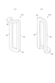
- 9(a) and 9(b) are perspective views showing the configuration of partial windings 81A and 81B.
- Each of the partial windings 81A and 81B is formed by winding a conductor material in multiple layers, and includes a pair of intermediate conductor portions 82 that are provided in parallel and in a straight line, and a pair of intermediate conductor portions 82 as an axis. It has a pair of transition portions 83 and 84 connected at both ends thereof.
- the pair of intermediate conductor portions 82 and the pair of bridge portions 83 and 84 form an annular shape.
- the pair of intermediate conductor portions 82 are spaced apart by a predetermined coil pitch, and the intermediate conductor portion 82 of the partial winding 81 of the other phase can be arranged between the pair of intermediate conductor portions 82 in the circumferential direction.
- the pair of intermediate conductor portions 82 are separated by two coil pitches, and one intermediate conductor portion 82 of the partial winding 81 of the other two phases is arranged between the pair of intermediate conductor portions 82. It is configured to be When the partial windings 81A and 81B are arranged side by side in the circumferential direction, the intermediate conductor portions 82 of the different partial windings 81A and 81B are arranged side by side in the circumferential direction in close proximity.
- the transition portions 83 and 84 on both sides in the axial direction are provided as portions corresponding to the coil ends CE1 and CE2 (see FIG. 4A).
- the other transition portion 84 is formed without being bent in the radial direction.
- the transition portion 83 is the "flexion side transition portion”
- the transition portion 84 is the "non-flexion side transition portion”.
- the bridging portion 83 is provided so as to be bent in a direction orthogonal to the intermediate conductor portion 82, that is, in a direction orthogonal to the axial direction.
- the partial windings 81A and 81B are substantially L-shaped when viewed from the side.
- the connecting portion 83 is bent radially in a different direction.
- the connecting portion 83 is bent radially inward
- the connecting portion 83 is bent radially outward. It is In this case, assuming that the partial windings 81A and 81B are arranged side by side in the circumferential direction, it is assumed that the crossover portions 83 of the partial windings 81A and 81B have different shapes in plan view (planar shapes in the radial direction). It is preferable that the crossover portion 83 of the partial winding 81A has a narrower circumferential width toward the distal end, and the crossover portion 83 of the partial winding 81B has a wider circumferential width toward the distal end.
- the intermediate conductor portions 82 are provided as coil side conductor portions arranged one by one in the circumferential direction on the coil side CS.
- each of the bridging portions 83 and 84 is provided as a coil end wire portion that connects the in-phase intermediate wire portions 82 at two different positions in the circumferential direction in the coil ends CE1 and CE2.
- the partial windings 81A and 81B are formed by winding the conductor material in multiple layers so that the cross section of the conductor assembly portion is square.
- the wire rods are arranged in a plurality of rows in the circumferential direction and in a plurality of rows in the radial direction, so that the cross section is formed to have a substantially rectangular shape.
- Each of the partial windings 81A and 81B is preferably covered with an insulating material in a state in which the conductor material is wound in multiple layers. Although a detailed description by illustration is omitted, it is preferable that each intermediate conductor portion 82 in the partial windings 81A and 81B is covered with a sheet-like insulating cover. For example, a configuration in which an insulating film material is wrapped around the intermediate conductor portion 82 is conceivable. Moreover, it is preferable that the transition portions 83 and 84 are attached with an insulating cover that is molded in accordance with the shape of the transition portion. The insulating cover can insulate the connecting portions of the partial windings 81A and 81B. Alternatively, the entire partial windings 81A and 81B may be coated with a resin material by resin immersion or the like.
- the position of the partial winding 81 is regulated by the position regulating member 70 on the coil end CE2 side (lower side in FIG. 4A). be.
- the position of the partial winding 81 is regulated by the position regulating member 100 different from the position regulating member 70 on the coil end CE1 side (upper side in FIG. 4A). That is, the position of each partial winding 81 is regulated by the position regulating member 70 on the side (CE2 side) where the transition portion 83 is bent radially outward among both ends in the axial direction, whereas the transition portion 83 is regulated in the radial direction.
- the position of the inwardly bent side (CE1 side) is restricted by the position restriction member 100 .
- FIG. 10(a) is a perspective view of the position regulating member 100
- FIG. 10(b) shows a state in which the first annular member 110 and the second annular member 120 constituting the position regulating member 100 are separated from each other. It is a perspective view showing.
- the position regulating member 100 has a first annular member 110 and a second annular member 120 which are formed in an annular shape and are provided in a state of being superimposed in the axial direction.
- the first annular member 110 is provided in contact with the axial end face of the stator core 42
- the second annular member 120 is axially opposite to the stator core 42 across the first annular member 110 .
- the position of the partial winding 81 is restricted by a position restricting member 100 having a first annular member 110 and a second annular member 120 that can be separated from each other.
- Each of the annular members 110 and 120 is a member that plays a role of regulating the position of the partial winding 81, and is preferably a highly rigid member.
- the annular members 110 and 120 are made of metal, such as aluminum, aluminum alloy, cast iron, or the like.
- the first annular member 110 has an annular portion 111 and restricting portions 112 and 113 provided on the annular portion 111 at predetermined intervals.
- the restricting portion 112 is provided so as to extend axially from the annular portion 111
- the restricting portion 113 is provided so as to extend radially outward from the annular portion 111 .
- These restricting portions 112 and 113 are arranged alternately in the circumferential direction.
- a through hole 114 is formed in each restricting portion 112 so as to extend therethrough in the axial direction.
- a plurality of restricting portions 112 among the restricting portions 112 arranged in the circumferential direction are provided with protruding portions 115 protruding radially inward.
- the second annular member 120 has an annular portion 121 and restricting portions 122 provided on the annular portion 121 at predetermined intervals.
- the restricting portion 122 is provided so as to extend axially from the annular portion 121 and is bent radially outward at its distal end side.
- a through hole 123 is formed through the annular portion 121 in the axial direction.
- the annular portions 111 and 121 of the respective annular members 110 and 120 are overlapped to form the respective annular members.
- the through holes 114 and 123 of the members 110 and 120 are communicated in the axial direction.
- the restricting portion 113 on the first annular member 110 side and the restricting portion 122 on the second annular member 120 side face each other while being spaced apart from each other in the axial direction (vertical direction in the figure).
- At least one of the annular members 110 and 120 is provided with an engaging portion by, for example, uneven engagement in order to suppress mutual positional deviation when the annular members 110 and 120 are superimposed. Good. As a result, the annular members 110 and 120 are prevented from being dislocated during assembly to the core assembly CA.
- the position regulating member 100 (the first annular member 110 and the second annular member 120) is fixed to the core assembly CA by a long bolt 101. Specifically, as shown in FIGS. 4A and 4B, the position regulating member 100 is attached to the axial end surface of the stator core 42 . In the assembled state, the through holes 114 and 123 of the annular members 110 and 120, the through hole 44 on the side of the stator core 42, and the hole portion 59 on the side of the stator holder 50 communicate in the axial direction. A position restricting member 100 is fixed to the core assembly CA by screwing a long bolt 101 into a series of holes.
- FIGS. 11(a) and 11(b) are enlarged views showing a part of FIGS. 4(a) and 4(b).
- FIG. 11(a) corresponds to FIG. b) corresponds to FIG. 4(b).
- the annular portion 71 of the position regulating member 70 and the large diameter portion 56 of the stator holder 50 face each other in the radial direction.
- a transition portion 84 (a transition portion on the non-flexing side) of the partial winding 81A is inserted into the annular space formed therebetween. This restricts the radial and axial positions of the partial winding 81A on the coil end CE2 side. Further, the restricting portion 75 of the position restricting member 70 enters the annular inner side of the transition portion 84 of the partial winding 81A, thereby restricting the circumferential and axial positions of the partial winding 81A on the coil end CE2 side.
- the restricting portion 76 of the position restricting member 70 enters the annular inner side of the transition portion 83 (flexion-side transition portion) of the partial winding 81B, thereby restricting the circumferential position of the partial winding 81B on the coil end CE2 side. It is
- the annular portion 111 of the first annular member 110 restricts the axial position of the partial winding 81A.
- the restricting portion 112 of the first annular member 110 enters the annular inner side of the transition portion 83 of the partial winding 81A, thereby restricting the circumferential and radial positions of the partial winding 81A on the coil end CE1 side. .
- the transition portion 84 of the partial winding 81B is arranged on the side of the coil end CE1. are restricted in their circumferential and axial positions.
- the position regulating members 70 and 100 are provided as common members for regulating the respective positions of the partial windings 81A and 81B.
- the wiring module 130 is a winding connection member that is electrically connected to the partial windings 81A and 81B in the stator winding 41.
- the wiring module 130 connects the partial windings 81 of each phase in parallel. Alternatively, they are connected in series, and the phase winding of each phase is connected to the neutral point.
- the wiring module 130 is provided on the coil end CE1 side, that is, on the side where the connecting portion 83 of the partial winding 81A is bent radially inward among both axial sides. ing.
- the wiring module 130 is formed in an annular shape, and is provided with a plurality of pedestals 131 at predetermined intervals in the circumferential direction.
- the wiring module 130 is fixed to the position regulating member 100 .
- the wiring module 130 is fixed to the position regulating member 100 by fixing the pedestal portion 131 to the projecting portion 115 (see FIG. 10A) provided on the first annular member 110 .
- the transition portions 84 of the partial winding 81B are arranged in a ring, and the wiring module 130 is provided radially inside the transition portions 84 .
- the wiring module 130 has a wiring member such as a busbar for each phase, and the wiring member is connected to the power input/output line of each phase.
- the power input/output lines of each phase are connected to an inverter (not shown) for power input/output.
- the wiring module 130 may be integrally provided with a current sensor that detects the phase current of each phase.
- the wiring module 130 may be formed in an annular shape according to the form of the stator winding 41, and may be a polygonal annular one or a substantially C-shaped one in which a part of the annular portion is missing. It may be of any shape.
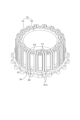
- FIG. 13 is an exploded perspective view in which the stator unit 30 is disassembled in order of assembly.
- FIG. 13 shows the stator unit 30 disassembled into the core assembly CA, partial winding 81A, position regulating members 70 and 100, partial winding 81B, and wiring module .
- 14 to 17 are perspective views showing the structure of the stator unit 30 during the assembly process.
- each partial winding 81A is arranged with the through hole 44 of the stator core 42 as the center position in the circumferential direction.
- the transition portion 84 of the partial winding 81A (the transition portion on the non-flexing side) faces the axial end face of the overhanging portion 52 of the stator holder 50, and They are arranged in the circumferential direction along the large diameter portion 56 .
- the position regulating member 70 on the coil end CE2 side is assembled to the assembly in the state of FIG. At this time, the position regulating member 70 is assembled from above in the axial direction, and the position regulating member 70 is fixed to the core assembly CA by screwing the bolt 77 .
- the transition portion 84 of each partial winding 81A enters between the annular portion 71 of the position regulating member 70 and the large diameter portion 56 of the stator holder 50, and the partial winding is performed on the coil end CE2 side.
- the radial position of the wire 81A is restricted.
- the restricting portion 75 of the position restricting member 70 enters between the pair of intermediate conductor portions 82 of each partial winding 81A and axially opposes the distal end portion of the transition portion 84, so that the partial winding is performed on the coil end CE2 side.
- the circumferential and axial positions of the wire 81A are restricted.
- the position regulating member 100 on the coil end CE1 side is assembled to the assembly in the state of FIG.
- Annular members 110 and 120 of position regulating member 100 are assembled from the axially outer side of transition portion 83 of partial winding 81A and fixed to core assembly CA by screwing long bolt 101 .
- the annular portion 111 of the first annular member 110 restricts the axial position of the partial winding 81A.
- the restricting portion 112 of the first annular member 110 enters the annular inner side of the transition portion 83 of the partial winding 81A, thereby restricting the circumferential and radial positions of the partial winding 81A on the coil end CE1 side.
- a plurality of partial windings 81B are attached to the assembly in the state of FIG.
- the partial winding 81B is assembled from the radially outer side so that each intermediate conductor portion 82 is inserted between the intermediate conductor portions 82 on the partial winding 81A side.
- the restricting portion 76 of the position restricting member 70 enters the annular inner side of the transition portion 83 of the partial winding 81B, thereby restricting the circumferential position of the partial winding 81B on the coil end CE2 side.
- the transition portion 84 of the partial winding 81B is arranged between the restricting portion 113 of the first annular member 110 and the restricting portion 122 of the second annular member 120, the partial winding 81B is arranged on the side of the coil end CE1. are regulated in circumferential and axial positions.
- the wiring module 130 is attached to the assembly in the state of FIG. 17 (see FIG. 4(b)).
- a sheet-like (band-like) coil cover 140 is provided radially outwardly of the partial windings 81A and 81B as a restraining member for binding the partial windings 81A and 81B. installed.
- the coil cover 140 is an endless cover formed in an annular shape, and is provided so as to cover the partial windings 81A and 81B from the outside in the radial direction.
- the coil cover 140 is provided in a range including at least the coil side CS in the axial direction, and is divided into a plurality of parts in the axial direction as shown.
- the coil cover 140 may be provided as a single cover.
- the coil cover 140 is preferably made of a sheet material that has insulating properties and is flexurally deformable.
- the sheet material is, for example, an insulating resin sheet.
- the coil cover 140 may be spring-shaped and have binding force.
- the coil cover 140 may be configured using an insulating material such as synthetic resin, or may be configured such that the conductive material is covered with an insulating material such as synthetic resin. That is, it is preferable that the coil cover 140 has insulation at least on its outer surface.
- a string-like member may be wound radially outwardly of each of the partial windings 81A and 81B.
- a range including the stator windings 41 and the wiring module 130 is resin-molded.
- a resin molded portion 150 is formed by integrally resin-molding a range including the coil ends CE1, CE2 and the coil side CS on both sides in the axial direction.
- An insulating layer is formed between the wires 81A, 81B and the position regulating members 70, 100.
- FIG. 18A and 18B are cross-sectional views showing the stator unit 30 with the resin mold portion 150 added.
- 18(a) is a diagram corresponding to FIG. 4(a)
- FIG. 18(b) is a diagram corresponding to FIG. 4(b).
- the resin molded portion 150 extends in the axial direction from the position regulating member 70 on the one axial end side to the position regulating member 100 on the other axial end side, and It is provided to include each intermediate conductor portion 82 of the partial windings 81A and 81B.
- the transition portions 83, 84 of the partial windings 81A, 81B and the position regulating member 70 are arranged with a slight separation from each other, and the separated portions are filled with a resin material. An insulating layer is thus formed.
- the transition portions 83 and 84 of the partial windings 81A and 81B and the position regulating member 100 are arranged with a slight separation from each other, and the separated portions are filled with a resin material.
- An insulating layer is formed by
- an insulating layer is formed by filling a resin material between the intermediate conductor portions 82 arranged in the circumferential direction.
- each transition portion 83, 84 and position regulating members 70, 100 are separated from each other.
- a gap portion due to the separation is filled with a resin material.
- a resin material (insulating material) is interposed between the stator core 42 and the stator holder 50 .
- the stator core 42 and the stator holder 50 are formed with unevenness in the radially inner and outer facing portions (see FIG. 5), and the stator core 42 and the stator holder 50 are fitted together by fitting the unevenness. Combined.
- a resin material is interposed in the gap between these two members.
- the stator core 42 may be attached to the stator holder 50 by shrink fitting, pin fixing, or the like, in addition to the concave-convex fitting described above.
- the insulation layers of the coil ends CE1 and CE2 and the insulation layers of the coil sides CS that is, the insulation layers on the outer side in the axial direction of the stator core 42 and the insulation layers on the inner and outer sides in the radial direction of the stator core 42 are made of the same resin material. It should be
- the gap between the stator core 42 and the stator holder 50 can be used as a passage through which the resin material (insulating material) flows.
- passages resin passages
- the end surface 58 of the stator holder 50 is provided with a plurality of protrusions in the circumferential direction to form a gap between the end surface 58 of the stator holder 50 and the axial end surface of the stator core 42, and the gap
- the resin material to flow through.
- At least one of the stator core 42 and the stator holder 50 is provided with a through-hole penetrating between both end surfaces in the axial direction. The configuration may be such that it is used as a resin passage that makes it possible.
- the insulating layers of the coil ends CE1, CE2 and the insulating layer of the coil side CS may be made of different resin materials.
- the insulating material interposed between the intermediate conductor portions 82 of the partial windings 81A, 81B and the stator core 42 is preferably a resin material having a higher adhesive strength than the insulating layers of the coil ends CE1, CE2. This resin material is preferably cured at the same time during the preheating process during molding.
- the insulating material interposed between the intermediate conductor portion 82 of the partial windings 81A, 81B and the stator core 42 is a resin material having a higher thermal conductivity than the insulating layers of the coil ends CE1, CE2. good.
- the insulating layer between the intermediate conductor portion 82 and the stator core 42 is preferably made of resin having a thermal conductivity of 0.3 W/mK or more, for example.
- a temperature detection section 160 for detecting the temperature of the stator 40 may be provided inside the resin mold section 150 .
- the temperature detecting section 160 is provided integrally with the position regulating member 100 or the wiring module 130, for example, and these are collectively resin-molded.
- the resin mold part 150 should be provided at least on each of the coil ends CE1 and CE2. In other words, a configuration in which the resin molded portion 150 is not provided on the coil side CS may be employed.
- the partial windings 81A There is a concern that the insulation of the stator winding 41 may be impaired due to the contact between 81B and the position regulating members 70 and 100 .
- the resin molded portion 150 is provided and an insulating layer is interposed between the partial windings 81A, 81B and the position regulating members 70, 100, thereby suppressing deterioration in insulating properties. As a result, the insulation state of the stator winding 41 can be properly maintained.
- position regulation is performed in two different directions in each of the partial windings 81A and 81B. It becomes possible. Since the insulating layer is interposed between the transition portions 83, 84 and the position regulating members 70, 100, it is possible to suppress the deterioration of the insulation properties of the partial windings 81A, 81B due to the position regulating members 70, 100.
- each of the partial windings 81A and 81B is formed in an annular shape by multiple windings of a conductive wire on the basis of the inner circumference side.
- the separation distance (insulation distance) between the transition portions 83 and 84 and the position regulating members 70 and 100 is designed.
- tolerance design of the partial windings 81A and 81B is facilitated.
- the partial windings 81A and 81B are caused to interfere with each other. Instead, they can be arranged so as to overlap each other in the circumferential direction. In this case, since the positions of the partial windings 81A and 81B are restricted using the common position restriction members 70 and 100, the number of parts can be reduced and the configuration can be simplified.
- the transition portions of the partial windings 81A and 81B 83 and 84 are arranged close to each other.
- the position regulating members 70 and 100 are provided so as to enter the annular inner side of the connecting portion of the partial winding 81A and the annular inner side of the connecting portion of the partial winding 81B. made it This makes it possible to easily achieve positional regulation in a plurality of directions in each of the partial windings 81A and 81B.
- the position regulating member 100 is set in a state of being inserted into the annular inner side of the transition portion 83 of the partial winding 81A at the coil end CE1, and is set to a state of facing the transition portion 84 of the partial winding 81B from the outside in the axial direction. It was configured. In this case, in the coil end CE1, the position regulating member 100 can be assembled while considering the bending states of the transition portions 83 and 84 of the partial windings 81A and 81B.
- the position regulating member 100 is configured to have portions (regulating portions 113 and 122) that sandwich the circumferentially extending portion of the transition portion 84 of the partial winding 81B from the annular outer side and the annular inner side, respectively. In this case, since the transition portion 84 of the partial winding 81B is sandwiched from both sides in the axial direction by the position regulating members 100, the position in the axial direction can be properly regulated.
- an annular position regulating member 100 is provided so as to face the transition portions 83 and 84 arranged in the circumferential direction,
- the annular wiring module 130 is fixed to the position regulating member 100 (specifically, the second annular member 120).
- each member is integrally resin-molded within a range including the transition portions 83, 84 of each partial winding 81A, 81B and the position regulating members 70, 100.
- the resin molded portion 150 is formed using the same resin material in each of the coil ends CE1 and CE2.
- an insulating layer is appropriately formed in the portions facing the position regulating members 70 and 100 (the gaps between the transition portions and the position regulating members) around the transition portions 83 and 84 of the partial windings 81A and 81B. can do.
- the structural members including the respective position regulating members 70 and 100 on both ends in the axial direction and the intermediate conductor portions 82 of the partial windings 81A and 81B are resin-molded. Thereby, the resin molded portion 150 is formed in a range including the entire partial windings 81A and 81B, and unintended insulation deterioration in the partial windings 81A and 81B can be appropriately suppressed.
- the gap between the intermediate conductor portions 82 of the partial windings 81A, 81B and the stator core 42 is a resin material having a higher adhesive strength than the insulating layers of the coil ends CE1 and CE2.
- the intermediate conductor portions 82 of the partial windings 81A and 81B and the stator core 42 and the stator holder 50 is a resin material having a higher thermal conductivity than the insulating layers of the coil ends CE1 and CE2. As a result, it is possible to improve the cooling performance of the intermediate conductor portion 82 .
- the temperature detection part 160 is integrally resin-molded together with the transition parts 83, 84 of the partial windings 81A, 81B and the position regulating member 100. As a result, the resin molded portion 150 can both transfer heat to the temperature detecting portion 160 and fix the temperature detecting portion 160 .
- stator unit 30 By interposing an insulating material forming an insulating layer between the stator core 42 and the stator holder 50, rattling of the stator core 42 with respect to the stator holder 50 can be suppressed. Further, in this case, when the stator unit 30 is manufactured, the gap between the stator core 42 and the stator holder 50 is used as a passage for the insulating material (resin material) to flow. , CE2 can be easily formed (resin molding).
- Passages are formed between the stator core 42 and the stator holder 50 so as to extend in the axial direction at predetermined intervals in the circumferential direction and to allow the flow of the insulating material when the stator unit 30 is manufactured. I hope it is.
- the fixture (long bolt 101) is inserted through each through hole of the stator core 42 and the position regulating member 100, and the fixture is inserted. , are fastened on the opposite side of the position regulating member 100 with the stator core 42 interposed therebetween. This allows the stator core 42 and the position regulating member 100 to be fixed simultaneously.
- FIG. 19(a) and (b) are perspective views showing the appearance of the stator unit 30, of which FIG. 19(b) shows a state where the resin mold provided in the stator unit 30 is removed.
- . 20 is a plan view of the stator unit 30,
- FIG. 21(a) is a cross-sectional view along the line 21a-21a of FIG. 20,
- FIG. 21(b) is a cross-sectional view along the line 21b-21b of FIG. be.
- FIG. 22 is an exploded perspective view showing the core assembly CA and the position regulating member 170 attached to the coil end CE2 side of the core assembly CA in this embodiment.
- the configuration of the coil end CE2 side of the configuration for restricting the winding position in the coil ends CE1 and CE2 is changed. ing.
- a hole portion 59 provided in the large-diameter portion 56 is a through hole penetrating in the axial direction.
- other configurations of the core assembly CA are the same as those shown in FIG. 5 and the like. Also, since there is no change in the configuration of the position regulating member 100 on the coil end CE1 side, description thereof will be omitted.
- the position regulating member 170 is formed in an annular shape, and has an end plate located axially outside the axial end face (lower end face in the drawing) of the large diameter portion 56 of the stator holder 50 . and an annular wall portion 172 extending axially from the outer edge of the end plate portion 171 .
- the end plate portion 171 is provided with a plurality of boss portions 173 at predetermined intervals in the circumferential direction, and each of the boss portions 173 is formed with a through hole 174 penetrating therethrough in the axial direction.
- the annular wall portion 172 is formed to have a larger diameter than the large diameter portion 56 .
- a plurality of restricting portions 175 are provided on the annular wall portion 172 so as to extend in the axial direction.
- the restricting portions 175 are convex portions extending in the circumferential direction, and are provided at predetermined intervals in the circumferential direction.
- the position regulating member 170 is made of, for example, aluminum, an aluminum alloy, cast iron, or the like.
- the position regulating member 170 has a boss portion 173 that is the axial end face of the large diameter portion 56 of the stator holder 50 (lower end face in the drawing). is attached to the stator holder 50 in a state of abutting on the . In this state, the annular wall portion 172 of the position regulating member 170 and the large diameter portion 56 of the stator holder 50 face each other in the radial direction. 84 (transition portion on the non-flexing side) is inserted. This restricts the radial and axial positions of the partial winding 81A on the coil end CE2 side.
- the restricting portion 175 of the position restricting member 170 enters the ring-shaped inner side of the transition portion 83 (flexion-side transition portion) of the partial winding 81B, thereby restricting the circumferential position of the partial winding 81B on the coil end CE2 side.
- the annular wall portion 172 may be provided with a plurality of restricting portions extending radially inward at predetermined intervals in the circumferential direction.
- the restricting portion enters the annular inner side of the transition portion 84 of the partial winding 81A, thereby restricting the circumferential and axial positions of the partial winding 81A on the coil end CE2 side.
- FIGS. 23(a) and 23(b) are cross-sectional views showing the stator unit 30 with the resin mold portion 150 added.
- 23(a) is a diagram corresponding to FIG. 21(a)
- FIG. 23(b) is a diagram corresponding to FIG. 21(b).
- the resin molded portion 150 extends in the axial direction from the position regulating member 170 on the one axial end side to the position regulating member 100 on the other axial end side, and It is provided to include each intermediate conductor portion 82 of the partial windings 81A and 81B.
- the configuration is substantially the same as that of FIGS. 18(a) and 18(b). That is, in each of the coil ends CE1 and CE2, the resin material enters between the transition portions 83 and 84 of the partial windings 81A and 81B and the position regulating members 70 and 100 to form an insulating layer. .
- a resin material (insulating material) is interposed between the stator core 42 and the stator holder 50 .
- the portion of the position regulating member 170 that is opposite to the stator holder 50 across the transition portion 84 of the partial winding 81A and that surrounds the transition portion 84 from the outside in the radial direction is It is a non-molded portion that is not resin-molded (X portion in FIG. 23).
- a part of the position regulating member 170 is exposed to the outside without being resin-molded, thereby improving heat dissipation. That is, in the rotary electric machine 10 , for example, lubricating oil may be dripped inside the rotor carrier 21 to lubricate the stator 40 .
- the non-molded portion (exposed portion) of the position regulating member 170 serves as a heat radiating portion by oil cooling.
- an end plate portion 171 of the position regulating member 170 which is located axially outside the axial end surface of the stator holder 50 , is provided with a hole portion 176 penetrating therethrough in the axial direction.
- the hole portion 176 is preferably provided at a position that does not interfere with the boss portion 173 . In this case, it is possible to fill the annular groove surrounding the large-diameter portion 56 of the stator holder 50 with the resin material through the hole 176 . Therefore, an insulating layer can be properly formed around the position regulating member 170 .
- FIG. 24(a) and (b) are perspective views showing the appearance of the stator unit 200, of which FIG. 24(a) shows the stator unit 200 in a resin-molded state and FIG. ) shows the stator unit 200 without resin molding.
- FIG. 25(a) is a vertical cross-sectional view of the stator unit 200 in a resin-molded state
- FIG. 25(b) is a vertical cross-sectional view of the stator unit 200 in a non-resin-molded state.
- FIG. 26 is an exploded perspective view showing the main components of the stator unit 200.
- the stator unit 200 has a stator 210, a radially inner stator holder 220, and a wiring module 230 as an overview.
- the stator 210 has a toothless structure and has a stator winding 211 and a stator core 212 .
- the stator core 212 and the stator holder 220 are integrally provided as a core assembly CA (see FIG. 26), and the stator windings 211 are assembled to the core assembly CA.
- the stator 210 has substantially the same configuration as the stator 40 described above, and the stator winding 211 is composed of a plurality of partial windings 81A and 81B as described above.
- the stator core 212 has the same configuration as the stator core 42 except that it does not have a plurality of projections on its inner peripheral side.
- the detailed description of the configuration similar to that of the stator 40 is omitted.
- the side (upper side in the drawing) where the transition portion 83 of the partial winding 81A is bent radially inward is the coil end CE1
- the side where 83 is bent radially outward is the coil end CE2.
- the wiring module 230 also has the same configuration as the wiring module 130, so description thereof will be omitted.
- the stator holder 220 has a cylindrical portion 221 to which the stator core 212 is assembled.
- a flange portion 222 extending radially inward is formed at the axial end portion of the cylindrical portion 221 on the side of the coil end CE1. It is
- Each boss portion 223 is provided with a hole portion 223a extending in the axial direction.
- a female screw is formed in each of the holes 223a.
- a protruding portion 225 that protrudes radially outward from the cylindrical portion 221 is provided at the axial end portion on the coil end CE2 side.
- the projecting portion 225 includes an end plate portion 226 extending radially outward from the cylindrical portion 221 (large diameter portion 221a) of the stator holder 220, and an annular annular wall extending axially from the outer edge portion of the end plate portion 226. 227.
- the annular wall portion 227 is formed to have a larger diameter than the large diameter portion 221a.
- a plurality of restricting portions 228 are provided on the annular wall portion 227 so as to extend in the axial direction.
- the restricting portions 228 are convex portions extending in the circumferential direction, and are provided at predetermined intervals in the circumferential direction.
- the projecting portion 225 of the stator holder 220 functions as a position regulating member that regulates the positions of the partial windings 81A and 81B assembled to the core assembly CA on the coil end CE2 side.
- the stator holder 220 is made of, for example, metal such as aluminum or cast iron, or carbon fiber reinforced plastic (CFRP). Although not shown, the stator holder 220, like the stator holder 50, preferably has a coolant passage through which a coolant such as cooling water flows.
- CFRP carbon fiber reinforced plastic
- a position regulating member 240 that regulates the position of the partial winding 81 is attached to the boss portion 223 of the stator holder 220 .
- the position regulating member 240 has an annular portion 241 and a plurality of regulating portions 242 provided on the annular portion 241 at predetermined intervals.
- the restricting portion 242 is provided so as to extend axially from the annular portion 241 .
- the annular portion 241 is formed with a plurality of through holes 243 extending axially as bolt insertion holes.
- the position regulating member 240 is fixed to the stator holder 220 with bolts 245 .
- the position regulating member 240 is made of, for example, aluminum, aluminum alloy, cast iron, or the like.
- a regulating portion 242 that enters the annular inner side of the transition portion 83 of the partial winding 81A is provided on either the radially inner or outer side of the annular portion 241, and , through-holes 243 (fixed portions) that are fixed to the stator holder 220 by bolts 245 are provided.
- the regulating portion 242 and the through hole 243 (fixed portion) are provided at radially inner and outer positions of the position regulating member 240, the positional regulation of the connecting portions 83 arranged in the circumferential direction is hindered. It is possible to fix the position regulating member 240 to the stator holder 220 without doing so.
- the regulating portion 242 becomes smaller due to the restriction of the fixed portion.
- the restricting portion 242 can be provided with sufficient strength.
- each partial winding 81A, 81B will be described in detail with reference to FIGS. 25 to 27.
- FIG. On the coil end CE2 side (lower side in the drawing), the large diameter portion 221a of the stator holder 220 and the annular wall portion 227 of the projecting portion 225 face each other in the radial direction. , the transition portion 84 (the transition portion on the non-bending side) of the partial winding 81A is inserted. This restricts the radial and axial positions of the partial winding 81A on the coil end CE2 side.
- the restricting portion 228 of the projecting portion 225 enters the annular inner side of the transition portion 83 (transition portion on the bending side) of the partial winding 81B, thereby restricting the circumferential position of the partial winding 81B on the coil end CE2 side.
- the axial position of the partial winding 81A is regulated by the annular portion 241 of the position regulating member 240.
- the restricting portion 242 of the position restricting member 240 enters the annular inner side of the transition portion 83 of the partial winding 81A, thereby restricting the circumferential and radial positions of the partial winding 81A on the coil end CE1 side.
- a position regulating member 240 (first position regulating member), which is a separate member from the stator holder 220, is fixed by a bolt 245, while on the side of the coil end CE1, the position regulating member 240 protrudes in the radial direction.
- the overhanging portion 225 (second position regulating member) is integrally formed with the stator holder 220 in a state where the stator holder 220 is closed. According to this configuration, when the partial windings 81A and 81B are assembled to the stator holder 220, the partial windings are first positioned while being restricted by the projecting portion 225 integrally formed on the stator holder 220.
- the position restricting member 240 can be retrofitted to the assembly including the stator holder 220 and the partial windings 81A, 81B.
- the number of parts can be reduced and the assembly work can be simplified, while at the same time, the proper position control member for each of the partial windings 81A and 81B can be obtained. positional regulation can be applied.
- a resin molded portion 250 is formed in a range including the stator windings 211 and the wiring module 230 .
- the configuration of the resin mold portion 250 will be described with reference to FIG. 25(a).
- the resin molded portion 250 extends in the axial direction from the projecting portion 225, which is the position regulating member on one axial end side, to the position regulating member 240 on the other axial end side, and is located between the partial windings 81A and 81B. It is provided to include a conductor portion 82 . In this case, in each of the coil ends CE1 and CE2, the resin material enters between the transition portions 83 and 84 of the partial windings 81A and 81B and the projecting portion 225 and the position regulating member 240, forming an insulating layer. It is configured.
- the portion of the protruding portion 225 that is opposite to the stator holder 220 across the transition portion 84 of the partial winding 81A and surrounds the transition portion 84 from the outside in the radial direction is It is a non-molded portion that is not resin-molded (X portion in FIG. 25(a)). In this case, a part of the overhanging portion 225 is not resin-molded and is exposed to the outside, thereby improving heat dissipation.
- the partial winding 81A has the connecting portion 83 bent radially inward, and the partial winding 81B has the connecting portion 83 bent radially outward.
- the wire length of the partial winding 81A is shorter, and the resistance of the wire is lower, so that the amount of heat generated is likely to be larger.
- the transition portion 83 of the partial winding 81A is accommodated in the annular groove portion formed by the protruding portion 225, thereby enhancing heat dissipation.
- the heat is preferably dissipated to the cooling passages provided in the stator holder 220 .
- FIG. 28 is a perspective view showing the configuration of the stator unit 200 of this embodiment
- FIG. 29 is a perspective view showing a state in which the position regulating member 260 is separated from the stator unit 200 of this embodiment.
- the stator unit 200 is configured to include a position restricting member 260 as a position restricting portion on the coil end CE1 side.
- the stator unit 200 shown in FIG. 28 is different from the stator unit 200 shown in FIG.
- the configuration other than the member 260 is generally the same.
- the configurations of the core assembly CA and the stator winding 211 are the same as in FIG.
- the position regulating member 260 has a first annular portion 261, a second annular portion 262, and a plurality of connecting portions 263 that axially connect the annular portions 261 and 262. are doing.
- the first annular portion 261 is provided with a plurality of axially extending restricting portions 264 at predetermined intervals and a plurality of axially penetrating holes 265 and 266 .
- the hole portions 265 are provided at the same pitch as the restricting portions 264 in the circumferential direction, and the hole portions 265 and the restricting portions 264 are alternately arranged in the circumferential direction.
- the hole portion 266 is provided as a bolt insertion hole through which the bolt 245 is inserted.
- a plurality of axially extending restricting portions 267 are provided at predetermined intervals on the second annular portion 262 .
- a position restricting member 260 is attached to the stator holder 220 on the side of the coil end CE1 (upper side in the drawing).
- the first annular portion 261 of the position restricting member 260 regulates the axial position of the partial winding 81A
- the second annular portion 262 regulates the axial position of the partial winding 81B. position
- the restricting portion 264 of the position restricting member 260 enters the ring-shaped inner side of the transition portion 83 (flexion-side transition portion) of the partial winding 81A, so that the partial winding 81A is rotated in the circumferential and radial directions on the coil end CE1 side. position is restricted.
- the restricting portion 267 of the position restricting member 260 enters between the transition portions 84 (transition portions on the non-flexing side) of the respective winding portions 81B arranged in the circumferential direction, so that the winding portions 81B are aligned on the side of the coil end CE1.
- the position in the circumferential direction is regulated.
- the position regulating member 260 is inserted into the circular inner side of the connecting portion 83 of the partial winding 81A, while facing the circular outer side of the connecting portion 84 of the partial winding 81B. It was configured to be in the state. In this case, the position regulating member 260 can be assembled while considering the bent state of the transition portions 83 and 84 of the partial windings 81A and 81B. In addition, after the partial windings 81A and 81B are assembled, the position regulating member 260 can be axially assembled, thereby facilitating the manufacturing work.
- the first annular portion 261 of the position regulating member 260 is provided with the hole portion 265 penetrating in the axial direction, the first annular portion The flow of the resin material from the outside in the axial direction of 261 to the inside in the axial direction is encouraged. As a result, resin molding is performed in a range including the inside of the hole portion 265 and both sides of the first annular portion 261 in the axial direction. In this case, the resin material reliably flows between the transition portions 83 and 84 of the partial windings 81A and 81B and the position regulating member 260, thereby forming an appropriate resin mold portion 250 (forming an insulating layer). can be realized.
- FIG. 30 is a perspective view showing the configuration of the stator unit 200 of this embodiment
- FIG. 31 is a perspective view showing a state in which the position regulating members 270 and 280 are separated from each other in the stator unit 200 of this embodiment. be.
- the stator unit 200 is configured to include a position restricting member 270 as a position restricting portion on the coil end CE1 side and a position restricting member 280 as a position restricting portion on the coil end CE2 side.
- the configuration of the stator winding 211 is the same as the configuration described above.
- the position restricting member 270 includes an annular portion 271, a plurality of restricting portions 272 extending radially inward from the annular portion 271, and a plurality of restricting portions extending axially from the annular portion 271. 273.
- the restricting portion 273 extends axially from the annular portion 271 and has a shape that is bent at its distal end side and extends radially outward. Further, the annular portion 271 is provided with a projecting portion 274 extending in the axial direction as a portion to be attached to a stator holder (not shown).
- the position regulating member 280 has an annular portion 281, a plurality of regulating portions 282 extending axially from the annular portion 281, and a plurality of regulating portions 283 extending radially outward from the annular portion 281. ing. Further, the annular portion 281 is provided with a projecting portion 284 extending radially inward as a portion to be attached to a stator holder (not shown).
- a position restricting member 270 is attached to the stator holder 220 on the side of the coil end CE2 (lower side in the drawing).
- the restricting portion 272 of the position restricting member 270 enters the ring-shaped inner side of the transition portion 84 of the partial winding 81A (the transition portion on the non-flexing side) of the winding portion 81A, thereby causing the axial movement of the partial winding 81A on the side of the coil end CE2.
- Direction and circumferential position are restricted.
- the regulating portion 273 of the position regulating member 270 enters the annular inner side (bending-side transition portion) of the transition portion 83 of the partial winding 81B, the axial direction and the circumferential direction of the partial winding 81B on the coil end CE2 side. position is restricted.
- a position regulating member 280 is attached to the stator holder 220 on the side of the coil end CE1 (upper side in the drawing).
- the restricting portion 282 of the position restricting member 280 enters the ring-shaped inner side of the transition portion 83 (flexion-side transition portion) of the partial winding 81A, thereby causing the partial winding 81A to move in the circumferential direction on the coil end CE1 side. and radial positions are restricted.
- the restricting portion 283 of the position restricting member 280 enters the annular inner side of the transition portion 84 of the partial winding 81B (transition portion on the non-flexing side), the partial winding 81B is moved in the axial direction and the circumferential direction on the coil end CE1 side. position is regulated.
- the configuration is such that the resin molded portion is formed at each of the coil ends CE1 and CE2 on both sides in the axial direction. good.
- the position regulating members for regulating the positions of the partial windings 81A and 81B are provided at the coil ends CE1 and CE2 on both sides in the axial direction. It is good also as a structure which provides a member. In this case, it is preferable that the coil cover 140 constrains the partial windings 81A and 81B while restricting the positions of the partial windings 81A and 81B only on one side in the axial direction.
- the stator units 30, 200 are configured to include the stator cores 42, 212, but this may be changed to a configuration that does not include the stator cores 42, 212.
- each partial winding 81A, 81B is assembled to the stator holder 50,220.
- an insulating layer resin material
- one partial winding 81A of the two types of partial windings 81A and 81B has a substantially C-shape when viewed from the side, and the other partial winding 81B has a substantially I-shape when viewed from the side. shape.
- the partial winding 81A and 81B the partial winding 81A is pre-attached to the core assembly CA, and the partial winding 81B is post-attached to the core assembly CA.
- a position regulating member is attached to the transition portion of each partial winding 81A, 81B, and the transition portion and the position regulating member are collectively resin-molded.
- the axial end faces of the stator cores 42, 212 and the axial end faces of the stator holders 50, 220 are flush with each other on the coil end CE1 side. good.
- the axial end faces of the stator holders 50 and 220 may project axially beyond the axial end faces of the stator cores 42 and 212 . In this case, an effect of improving heat dissipation can be expected.
- the stator winding 41 in the rotating electrical machine 10 may be configured to have two phase windings (a U-phase winding and a V-phase winding).
- a pair of intermediate conductor portions 82 are provided separated by one coil pitch. may be arranged as long as one is arranged.
- a surface magnet type rotor is used as the rotor 20, but instead of this, an embedded magnet type rotor may be used.
- the rotating electrical machine 10 has an outer rotor structure, but this may be changed to a rotating electrical machine with an inner rotor structure.
- a stator is provided radially outward and a rotor is provided radially inward.
- a rotating armature type rotating electric machine having a field element as a rotor and an armature as a stator is replaced with a rotating field type rotating electric machine having an armature as a rotor and a field element as a stator. It is also possible to employ a rotating electric machine.
- the application of the rotating electrical machine 10 may be other than a driving motor for a vehicle, and may be a rotating electrical machine widely used in moving bodies including aircraft, or a rotating electrical machine used in industrial or household electrical equipment. .
- the disclosure in this specification is not limited to the illustrated embodiments.
- the disclosure encompasses the illustrated embodiments and variations thereon by those skilled in the art.
- the disclosure is not limited to the combinations of parts and/or elements shown in the embodiments.
- the disclosure can be implemented in various combinations.
- the disclosure can have additional parts that can be added to the embodiments.
- the disclosure encompasses omitting parts and/or elements of the embodiments.
- the disclosure encompasses permutations or combinations of parts and/or elements between one embodiment and another.
- the disclosed technical scope is not limited to the description of the embodiments.
- the disclosed technical scope is indicated by the description of the claims, and should be understood to include all modifications within the meaning and range of equivalents to the description of the claims.
- the partial winding includes a pair of intermediate conductor portions (82) provided at a predetermined interval in the circumferential direction, and transition portions provided at one end side and the other end side in the axial direction and connecting the pair of intermediate conductor portions in an annular fashion.
- Position regulating members (70, 100, 170, 225, 240, 260, 260, 70, 100, 170, 225, 240, 260, 70, 100, 170, 225, 240, 260, 70, 100, 170, 225, 240, 260, 70, 70, 70, 70, 70, 70, 70, 70, 70, 70, 70, 70, 70, 70, 70, 70, and 270, 280) regulate the positions of the partial windings assembled to the armature holding member, A rotating electric machine, wherein an insulating layer (150, 250) is interposed between the partial winding and the position regulating member.
- the armature winding has, as the partial windings, a first partial winding and a second partial winding in which the shape of the transition portion at the coil end is different, At least one of the first partial winding and the second partial winding is arranged to overlap each other in the circumferential direction with at least one of the winding ends bent in the radial direction,
- the position regulating member as the common member is inserted into a portion of the first partial winding that is annularly inside the transition portion and a portion of the second partial winding that is annularly inside of the transition portion.
- the position regulating member is a member provided separately from the armature holding member and fixed to the armature holding member by a fixture (101, 245); In the coil end, the connecting portion of the first partial winding is bent in the radial direction, and the connecting portion of the second partial winding is not bent in the radial direction, The position regulating member, which is the common member, enters the annular inner side of the transition portion of the first partial winding, while being the annular outer side of the transition portion of the second partial winding.
- the position regulating member is A member provided separately from the armature holding member and fixed to the armature holding member by a fixture (245), having an annular portion (241, 261), A restricting portion (242, 264) is provided on either one of the radial inner and outer sides of the annular portion, and the restriction portion (242, 264) that enters the annular inner side of the transition portion of the partial winding is provided on the other side.
- each of the transition portions of the plurality of partial windings is arranged in a circumferential direction, and the ring-shaped position regulating member is provided so as to face each of the transition portions arranged in the circumferential direction; 9.
- a wiring module (130) electrically connected to each of the partial windings has an annular shape and is fixed to the position regulating member.
- the insulating layer is formed by integrally resin-molding these members in a range including the transition portion of the partial winding and the position regulating member in at least one of the coil ends on both sides in the axial direction.
- the rotating electrical machine according to any one of Configurations 1 to 9.
- a through hole (265) passing through the annular portion (261) in the axial direction is provided in the position regulating member, and resin molding is performed within a range including the inside of the through hole and both sides of the annular portion in the axial direction.
- the armature has an armature core (42) provided radially inside or radially outside the armature winding, An insulating material is interposed between the intermediate conductor portion of the partial winding and the armature core, and the insulating material is a resin material having higher adhesion than the insulating layer in the coil end. 14.
- the rotating electric machine according to any one of 10 to 13.
- the armature has an armature core (42) provided radially inside or radially outside the armature winding, An insulating material is interposed between the intermediate conductor portion of the partial winding and the armature core, and the insulating material is a resin material having a higher thermal conductivity than the insulating layer in the coil end.
- a temperature detection unit (160) for detecting the temperature of the armature The electric rotating machine according to any one of configurations 10 to 15, wherein the temperature detection section is resin-molded together with the transition section and the position regulating member.
- a second coil end (CE1) which is a separate member from the armature holding member and is fixed to the armature holding member by a fixture (245), serves as the position regulating member.
- a one-position regulating member (240) is provided, Configuration 1, wherein a second position regulating member (225) as the position regulating member is integrally formed with the armature holding member in a radially projecting state on the second coil end (CE2) on the other side in the axial direction. 17.
- the rotary electric machine according to any one of 16.
- the armature winding includes, as the partial windings, a partial winding having the transition portion bent in the radial direction at the second coil end and a partial winding having the transition portion not radially bent at the second coil end.
- the second position regulating member has an annular wall portion (227) radially opposed to the cylindrical portion (221) of the armature holding member, and a gap between the cylindrical portion and the annular wall portion (227) is provided.
- the annular wall portion has a plurality of regulating portions (228) provided at predetermined intervals in the circumferential direction and extending in the axial direction, 19.
- the armature has an armature core (42) provided radially inside or radially outside the armature winding, The armature core is provided so as to face the armature holding member in a radial direction,
- the rotating electric machine according to any one of configurations 1 to 19, wherein an insulating material forming the insulating layer is interposed between the armature core and the armature holding member.
- the armature has an armature core (42) provided radially inside or radially outside the armature winding,
- the position regulating member is provided separately from the armature holding member, Through holes (44, 114, 123) extending through the armature core and the position regulating member in the axial direction are provided, respectively,
- a fixture (101) is inserted through each of the through-holes of the armature core and the position regulating member in a state in which the position regulating member is superimposed on the axial end face of the armature core, and the fixture is: 21.
- the rotating electric machine according to any one of configurations 1 to 20, wherein the armature core is interposed and fastened on the opposite side of the position regulating member.
Landscapes
- Engineering & Computer Science (AREA)
- Power Engineering (AREA)
- Insulation, Fastening Of Motor, Generator Windings (AREA)
Abstract
回転電機(10)は、複数の磁極を有する界磁子(20)と、多相の電機子巻線(41)を有するティースレス構造の電機子(40)と、電機子を保持する電機子保持部材(50)と、を備えている。電機子巻線において、部分巻線(81)は、一対の中間導線部(82)と渡り部(83,84)とを有しており、互いに異なる部分巻線の各中間導線部どうしが近接状態で周方向に並べて配置されている。電機子のコイルエンドにおいて、電機子保持部材の一部又は電機子保持部材に固定された部材である位置規制部材(70,100)により、電機子保持部材に組み付けられた状態での部分巻線の位置が規制されている。部分巻線と位置規制部材との間には絶縁層(150)が介在している。
Description
本出願は、2021年9月3日に出願された日本出願番号2021-144252号に基づくもので、ここにその記載内容を援用する。
この明細書における開示は、回転電機に関する。
従来、周方向に極性が交互となる複数の磁極を有する磁石部を含む界磁子と、多相の電機子巻線を有する電機子と、を備える回転電機が知られている。また、電機子としてティースレス構造を有するものが知られており、このティースレス構造の電機子では、電機子コアのティースに電機子巻線が巻装される構成とは異なり、電機子巻線の位置ずれが生じることが懸念される。そこで、例えば、電機子巻線の軸方向端部であるコイルエンドに巻線規制部材(コイルエンドホルダ)を取り付け、その巻線規制部材を電機子巻線に係合させることで電機子巻線の位置を規制するようにした技術が提案されている(特許文献1参照)。
巻線規制部材により電機子巻線の位置を規制する場合、剛性の観点から巻線規制部材が金属製であることが望ましい。しかしながら、金属製の巻線規制部材を用いる場合、電機子巻線の絶縁性が損なわれることの懸念が考えられる。
本開示は、上記事情に鑑みてなされたものであり、電機子巻線の絶縁状態を適正に維持することができる回転電機を提供することを目的とする。
この明細書における開示された複数の態様は、それぞれの目的を達成するために、互いに異なる技術的手段を採用する。この明細書に開示される目的、特徴、および効果は、後続の詳細な説明、および添付の図面を参照することによってより明確になる。
手段1は、
複数の磁極を有する界磁子と、多相の電機子巻線を有するティースレス構造の電機子と、前記電機子を保持する電機子保持部材と、を備える回転電機であって、
前記電機子巻線は、相ごとに複数の部分巻線からなる相巻線を有し、
前記部分巻線は、周方向に所定間隔を離して設けられる一対の中間導線部と、軸方向一端側及び他端側に設けられ前記一対の中間導線部を環状に接続する渡り部とを有し、互いに異なる部分巻線の各中間導線部どうしが近接状態で周方向に並べて配置されており、
前記電機子のコイルエンドにおいて、前記電機子保持部材の一部又は前記電機子保持部材に固定された部材である位置規制部材により、前記電機子保持部材に組み付けられた状態での前記部分巻線の位置が規制されており、
前記部分巻線と前記位置規制部材との間に絶縁層が介在している。
ティースレス構造の電機子を有する回転電機では、電機子巻線を固定する構造が必要となる。この点、電機子を保持する電機子保持部材を用い、電機子巻線を構成する部分巻線の位置を、電機子保持部材の一部又は電機子保持部材に固定された部材である位置規制部材により規制することで、電機子巻線の適正な固定が可能となる。ただしこの場合、剛性の観点から金属製の位置規制部材を用いる構成にすると、部分巻線と位置規制部材との接触に伴い電機子巻線の絶縁性が損なわれることが懸念される。この懸念に対して、部分巻線と位置規制部材との間に絶縁層を介在させる構成としたため、絶縁性低下を抑制できる。その結果、電機子巻線の絶縁状態を適正に維持することができる。
手段2では、手段1において、前記位置規制部材は、前記コイルエンドにおいて前記渡り部の環状内側となる部位に入り込んだ状態で設けられており、前記渡り部と前記位置規制部材との間に前記絶縁層が介在している。
電機子のコイルエンドにおいて渡り部の環状内側となる部位に入り込んだ状態で位置規制部材が設けられていることにより、各部分巻線において異なる2方向での位置規制が可能となる。例えば、渡り部が軸方向に延びる構成(渡り部が径方向に屈曲されていない構成)では、その渡り部の環状内側に位置規制部材が入り込んでいることにより、周方向及び軸方向の位置規制が可能となる。また、渡り部が屈曲されて径方向に延びる構成では、その渡り部の環状内側に位置規制部材が入り込んでいることにより、周方向及び径方向の位置規制が可能となる。また、渡り部と位置規制部材との間に絶縁層が介在していることにより、やはり位置規制部材による部分巻線の絶縁性低下を抑制できる。
なお、部分巻線は内周側基準で導線材を多重に巻回して環状に形成されることが考えられる。この場合、渡り部の環状内側に位置規制部材を入り込ませる構成では、それら渡り部と位置規制部材との間の離間距離(絶縁距離)を設計する際において部分巻線の公差設計等が容易となっている。
手段3では、手段2において、前記電機子巻線は、前記部分巻線として、前記コイルエンドにおける前記渡り部の形状が相違している第1部分巻線及び第2部分巻線を有し、前記第1部分巻線及び前記第2部分巻線は、前記コイルエンドにおいて少なくともいずれか一方が径方向に屈曲された状態で互いに周方向に重なる状態で配置されており、前記位置規制部材は、前記第1部分巻線及び前記第2部分巻線の各位置を共に規制する共通部材として設けられている。
部分巻線として、コイルエンドにおける渡り部の形状が相違している第1部分巻線及び第2部分巻線を用いることにより、部分巻線どうしを相互に干渉させることなく、互いに周方向に重なる状態で配置することができる。この場合、第1部分巻線及び第2部分巻線の各位置を、共通の位置規制部材を用いて位置規制する構成にしたため、部品点数の削減や構成の簡素化を図ることができる。
手段4では、手段3において、前記共通部材としての前記位置規制部材が、前記第1部分巻線における前記渡り部の環状内側となる部位と、前記第2部分巻線における前記渡り部の環状内側となる部位とにそれぞれ入り込んだ状態で設けられている。
第1部分巻線及び第2部分巻線を、コイルエンドにおいて少なくともいずれか一方が径方向に屈曲された状態で互いに周方向に重なる状態で配置する場合、第1部分巻線及び第2部分巻線において各々の渡り部が近接配置される。この点を鑑み、位置規制部材を、第1部分巻線における渡り部の環状内側となる部位と、第2部分巻線における渡り部の環状内側となる部位とにそれぞれ入り込んだ状態で設けるようにした。これにより、各部分巻線において複数の方向における位置規制を簡易に実現することができる。
手段5では、手段3において、前記位置規制部材は、前記電機子保持部材とは別体で設けられ、当該電機子保持部材に対して固定具により固定される部材であり、前記共通部材としての前記位置規制部材が、前記第1部分巻線における前記渡り部の環状内側となる部位に入り込んだ状態になる一方、前記第2部分巻線における前記渡り部に軸方向外側から対向する状態にして設けられている。
共通部材としての位置規制部材を、第1部分巻線における渡り部の環状内側となる部位に入り込んだ状態にする一方、第2部分巻線における渡り部に軸方向外側から対向する状態にする構成とした。この場合、各部分巻線における渡り部の屈曲状態を加味しつつ位置規制部材を組み付けることができる。
手段6では、手段3において、前記位置規制部材は、前記電機子保持部材とは別体で設けられ、当該電機子保持部材に対して固定具により固定される部材であり、前記コイルエンドにおいて、前記第1部分巻線では前記渡り部が径方向に屈曲され、前記第2部分巻線では前記渡り部が径方向に屈曲されていない構成であり、前記共通部材としての前記位置規制部材が、前記第1部分巻線における前記渡り部の環状内側となる部位に入り込んだ状態になる一方、前記第2部分巻線における前記渡り部の環状外側となる部位に対向する状態にして設けられている。
共通部材としての位置規制部材を、第1部分巻線における渡り部の環状内側となる部位に入り込んだ状態にする一方、第2部分巻線における渡り部の環状外側となる部位に対向する状態にする構成とした。この場合、各部分巻線における渡り部の屈曲状態を加味しつつ位置規制部材を組み付けることができる。また、第1部分巻線及び第2部分巻線の組み付け後に、軸方向から位置規制部材を組み付けることが可能であり、作製作業を容易化できるものとなっている。
手段7では、手段6において、前記位置規制部材は、前記第2部分巻線の前記渡り部において周方向に延びる部分を、環状外側及び環状内側のそれぞれから挟み込む部位を有する。
第2部分巻線は、いずれかのコイルエンドにおいて径方向に屈曲されていない渡り部を有する部分巻線であり、その第2部分巻線の渡り部において周方向に延びる部分が、位置規制部材により環状外側及び環状内側のそれぞれから挟み込まれる構成にした。この場合、第2部分巻線の渡り部が、位置規制部材により軸方向両側から挟み込まれるため、軸方向の位置規制を適正に行わせることができる。
手段8では、手段1~7のいずれかにおいて、前記位置規制部材は、前記電機子保持部材とは別体で設けられ、当該電機子保持部材に対して固定具により固定される部材であり、環状をなす環状部を有し、前記環状部における径方向内外のうちいずれか一方の側に、前記部分巻線における前記渡り部の環状内側に入り込んだ状態となる規制部が設けられ、他方の側に、前記固定具により前記電機子保持部材に固定される被固定部が設けられている。
電機子保持部材とは別体で設けられた位置規制部材において、環状部における径方向内外のうちいずれか一方の側に、部分巻線における渡り部の環状内側に入り込んだ状態となる規制部を設けるとともに、他方の側に、固定具により電機子保持部材に固定される被固定部を設ける構成とした。この場合、位置規制部材において径方向内外に離れた位置に、部分巻線の位置規制のための規制部と、電機子保持部材に対して機械的に固定される被固定部とがそれぞれ設けられているため、周方向に並ぶ各渡り部の位置規制を邪魔することなく、電機子保持部材に対する位置規制部材の固定を行わせることができる。つまり、位置規制部材において、例えば径方向外側の位置に部分巻線の規制部と被固定部とを共に設ける構成にすると、被固定部の制約を受けて規制部が小さくなる等の懸念が生じるが、上記構成によれば、規制部を十分な強度を有するものとして設けることができる。
手段9では、手段1~8のいずれかにおいて、前記複数の部分巻線における前記各渡り部は周方向に並び、その周方向に並ぶ前記各渡り部に対向する状態で環状の前記位置規制部材が設けられており、前記各部分巻線に対して電気的に接続される配線モジュールが、環状をなし、かつ前記位置規制部材に対して固定された状態で設けられている。
各部分巻線の渡り部が周方向に並ぶ構成において、その周方向に並ぶ各渡り部に対向する状態で環状の位置規制部材を設けるとともに、環状の配線モジュールを、位置規制部材に対して固定する構成とした。これにより、部品点数の削減を図りつつ、周方向に並ぶ各部分巻線と配線モジュールとの電気的な接続を好適に実現することができる。
手段10では、手段1~9のいずれかにおいて、軸方向両側の前記コイルエンドのうち少なくともいずれかにおいて前記部分巻線の前記渡り部と前記位置規制部材とを含む範囲でこれら各部材が一体で樹脂モールドされることにより、前記絶縁層が形成されている。
軸方向の少なくともいずれかのコイルエンドにおいて部分巻線の渡り部と位置規制部材とを含む範囲でこれら各部材が一体で樹脂モールドされることにより、部分巻線の渡り部と位置規制部材とを含む範囲で同一の樹脂材料を用いて樹脂モールド部が形成されている。この場合、部分巻線の渡り部の周囲において位置規制部材に対向する部分(渡り部と位置規制部材との間の隙間部分)に適正に絶縁層を形成することができる。
手段11では、手段10において、前記位置規制部材において環状をなす環状部に、軸方向に貫通する貫通孔が設けられており、その貫通孔内と前記環状部の軸方向両側とを含む範囲で樹脂モールドがなされている。
位置規制部材の環状部に、軸方向に貫通する貫通孔が設けられていることにより、位置規制部材の軸方向外側から軸方向内側への樹脂材の流れが促される。これにより、部分巻線の各渡り部と位置規制部材との間への樹脂材の回り込みが確実に行われ、適正なる樹脂モールド部の形成(絶縁層の形成)を実現できる。
手段12では、手段10又は11において、前記位置規制部材において、前記渡り部を挟んで前記電機子保持部材の反対側であり、かつ当該渡り部を包囲する部位が、樹脂モールドがなされていない非モールド部となっている。
位置規制部材において、渡り部を挟んで電機子保持部材の反対側であり、かつ当該渡り部を包囲する部位を、樹脂モールドがなされていない非モールド部とした。この場合、位置規制部材の一部が樹脂モールドされずに外部に露出する露出部となっており、放熱性が向上する。例えば、油冷構造を有する構成では、位置規制部材の非モールド部(露出部)が油冷による放熱部となっている。
手段13では、手段10~12のいずれかにおいて、前記電機子保持部材には、軸方向一端側及び他端側にそれぞれ前記位置規制部材が設けられており、軸方向において軸方向一端側の前記位置規制部材から軸方向他端側の前記位置規制部材までの範囲であり、かつ前記部分巻線の前記中間導線部を含む構成部材が樹脂モールドされている。
軸方向において軸方向両端側の各位置規制部材と部分巻線の中間導線部とを含む構成部材を、樹脂モールドする構成とした。これにより、部分巻線の全体を含む範囲で樹脂モールドが形成され、部分巻線における意図しない絶縁低下を適正に抑制できる。
手段14では、手段10~13のいずれかにおいて、前記電機子は、前記電機子巻線の径方向内側又は径方向外側に設けられる電機子コアを有し、前記部分巻線の前記中間導線部と前記電機子コアとの間に絶縁材が介在しており、その絶縁材は、前記コイルエンドにおける前記絶縁層よりも接着力の高い樹脂材である。
部分巻線の中間導線部と電機子コアとの間に介在している絶縁材を、コイルエンドにおける絶縁層よりも接着力の高い樹脂材としたため、電機子コアに対する部分巻線の組み付け強度を高めることができ、部分巻線の位置ずれを好適に抑制することができる。
手段15では、手段10~14のいずれかにおいて、前記電機子は、前記電機子巻線の径方向内側又は径方向外側に設けられる電機子コアを有し、前記部分巻線の前記中間導線部と前記電機子コアとの間に絶縁材が介在しており、その絶縁材は、前記コイルエンドにおける前記絶縁層よりも熱伝導率の高い樹脂材である。
部分巻線の中間導線部と電機子コアとの間に介在している絶縁材を、コイルエンドにおける絶縁層よりも熱伝導率の高い樹脂材としたため、中間導線部での冷却性向上を図ることができる。
手段16では、手段10~15のいずれかにおいて、前記電機子の温度を検出する温度検出部を有し、前記温度検出部が、前記渡り部及び前記位置規制部材と共に樹脂モールドされている。
部分巻線の渡り部及び位置規制部材と共に温度検出部を一体的に樹脂モールドしたため、その樹脂モールド部により、温度検出部に対する熱伝達と温度検出部の固定とを両立させることができる。
手段17では、手段1~7のいずれかにおいて、前記電機子保持部材において、軸方向一方の第1コイルエンドには、前記位置規制部材として、前記電機子保持部材とは別部材でありかつ当該電機子保持部材に対して固定具により固定される第1位置規制部材が設けられ、軸方向他方の第2コイルエンドには、前記位置規制部材として、径方向に張り出した状態で第2位置規制部材が前記電機子保持部材に一体成形されている。
電機子保持部材の軸方向一端側の第1コイルエンドに、電機子保持部材とは別部材の第1位置規制部材を固定具により固定する一方、軸方向他端側の第2コイルエンドに、径方向に張り出した状態で第2位置規制部材を一体成形する構成とした。この構成よれば、電機子保持部材に対して各部分巻線を組み付ける場合において、先に、電機子保持部材に一体成形された第2位置規制部材により位置規制した状態で各部分巻線を組み付け、その後に、電機子保持部材及び部分巻線を含むアセンブリに対して、第1位置規制部材を後付けすることができる。この場合、軸方向両側の位置規制部材のうち一方を電機子保持部材に一体成形しておくことで、部品点数の削減や組み付け作業の簡略化を図りつつ、各部分巻線に対する適正な位置規制を施すことができる。
手段18では、手段17において、前記電機子巻線は、前記部分巻線として、前記第2コイルエンドにおいて径方向に屈曲された前記渡り部を有する部分巻線と、径方向に屈曲されていない前記渡り部を有する部分巻線とを有しており、前記第2位置規制部材は、前記電機子保持部材の円筒部に対して径方向に対向する環状の環状壁部を有し、前記円筒部と前記環状壁部との間に形成される環状溝部に、径方向に屈曲されていない前記渡り部が挿入されている。
電機子保持部材において径方向に張り出した状態で形成された第2位置規制部材に、環状の環状壁部を設け、電機子保持部材の円筒部と環状壁部との間に形成される環状溝部に、径方向に屈曲されていない渡り部を挿入する構成とした。この場合、環状溝部内に渡り部が挿入されることで、その渡り部を有する部分巻線において、径方向及び軸方向の位置規制が可能となる。
手段19では、手段18において、前記第2位置規制部材において、前記環状壁部は、周方向に所定間隔で設けられ軸方向に延びる複数の規制部を有し、前記第2位置規制部材における前記規制部が、径方向に屈曲された前記渡り部の環状内側に入り込んだ状態となっている。
第2位置規制部材の環状壁部に、周方向に所定間隔で、軸方向に延びる複数の規制部を設け、その規制部が、径方向に屈曲された渡り部の環状内側に入り込む状態とした。この場合、環状壁部の規制部が渡り部の環状内側に入り込むことで、その渡り部を有する部分巻線において、周方向の位置規制が可能となる。
手段20では、手段1~19のいずれかにおいて、前記電機子は、前記電機子巻線の径方向内側又は径方向外側に設けられる電機子コアを有し、前記電機子コアは、前記電機子保持部材に対して径方向に対向する状態で設けられており、前記電機子コアと前記電機子保持部材との間に、前記絶縁層を構成する絶縁材が介在している。
電機子コアと電機子保持部材との間に、絶縁層を構成する絶縁材が介在していることにより、電機子保持部材に対する電機子コアのがたつきを抑制することができる。またこの場合、電機子の製造時において、電機子コアと電機子保持部材との間の隙間を、絶縁材(樹脂材)が流れる通路として用いることにより、軸方向両側のコイルエンドでの絶縁層の形成(樹脂モールド)を簡易に実施することができる。
なお、電機子コアと電機子保持部材との間には、周方向に所定間隔で軸方向に延び、電機子の製造時に絶縁材の流通を可能とする通路(樹脂通路)が形成されているとよい。
手段21では、手段1~20のいずれかにおいて、前記電機子は、前記電機子巻線の径方向内側又は径方向外側に設けられる電機子コアを有し、前記位置規制部材は、前記電機子保持部材に対して別体で設けられ、前記電機子コア及び前記位置規制部材には、軸方向に貫通する貫通孔がそれぞれ設けられており、前記電機子コアの軸方向端面に前記位置規制部材が重ねられた状態で、前記電機子コア及び前記位置規制部材の前記各貫通孔に固定具が挿通され、かつその固定具が、前記電機子コアを挟んで前記位置規制部材の反対側で締結されている。
電機子コアの軸方向端面に位置規制部材を重ねた状態で、電機子コア及び位置規制部材の各貫通孔に固定具を挿通させ、かつその固定具を、電機子コアを挟んで位置規制部材の反対側で締結する構成とした。これにより、電機子コア及び位置規制部材の同時の固定が可能になっている。
本開示についての上記目的およびその他の目的、特徴や利点は、添付の図面を参照しながら下記の詳細な記述により、より明確になる。その図面は、
図1は、第1実施形態における回転電機の縦断面図であり、
図2は、固定子ユニットの外観を示す斜視図であり、
図3は、固定子ユニットの平面図であり、
図4は、(a)は図3の4a-4a線断面図、(b)は図3の4b-4b線断面図であり、
図5は、コアアセンブリの分解示す斜視図であり、
図6は、(a)はコアアセンブリの縦断面図、(b)はコアアセンブリの横断面図であり、
図7は、位置規制部材の斜視図であり、
図8は、コアアセンブリに対して位置規制部材を組み付けた状態を示す斜視図であり、
図9は、部分巻線の構成を示す斜視図であり、
図10は、位置規制部材の構成を示す斜視図であり、
図11は、固定子ユニットの縦断面図であり、
図12は、配線モジュールの斜視図であり、
図13は、固定子ユニットの分解斜視図であり、
図14は、固定子ユニットの組み立て過程を説明するための斜視図であり、
図15は、固定子ユニットの組み立て過程を説明するための斜視図であり、
図16は、固定子ユニットの組み立て過程を説明するための斜視図であり、
図17は、固定子ユニットの組み立て過程を説明するための斜視図であり、
図18は、固定子ユニットの縦断面図であり、
図19は、第2実施形態における固定子ユニットの外観を示す斜視図であり、
図20は、固定子ユニットの平面図であり、
図21は、(a)は図20の21a-21a線断面図、(b)は図20の21b-21b線断面図であり、
図22は、コアアセンブリと位置規制部材とを分解して示す斜視図であり、
図23は、固定子ユニットの縦断面図であり、
図24は、第3実施形態における固定子ユニットの外観を示す斜視図であり、
図25は、固定子ユニットの縦断面図であり、
図26は、固定子ユニットの分解斜視図であり、
図27は、固定子ユニットの分解斜視図であり、
図28は、第4実施形態における固定子ユニットの外観を示す斜視図であり、
図29は、固定子ユニットにおいて位置規制部材を分離させた状態を示す斜視図であり、
図30は、第5実施形態における固定子ユニットの外観を示す斜視図であり、
図31は、固定子ユニットにおいて位置規制部材を分離させた状態を示す斜視図であり、
図32は、変形例の部分巻線を示す図である。
図面を参照しながら、複数の実施形態を説明する。複数の実施形態において、機能的におよび/または構造的に対応する部分および/または関連付けられる部分には同一の参照符号が付される場合がある。対応する部分および/又は関連付けられる部分については、他の実施形態の説明を参照することができる。
本実施形態における回転電機は、例えば車両動力源として用いられるものとなっている。ただし、回転電機は、産業用、車両用、航空機用、家電用、OA機器用、遊技機用などとして広く用いられることが可能となっている。なお、以下の各実施形態相互において、互いに同一又は均等である部分には、図中、同一符号を付しており、同一符号の部分についてはその説明を援用する。
(第1実施形態)
本実施形態に係る回転電機10は、アウタロータ式の表面磁石型多相交流モータであり、車両のインホイールモータとして用いられる。図1は、回転電機10の縦断面図である。以下の記載では、回転電機10において、回転軸線の延びる方向を軸方向とし、回転軸線の中心から放射状に延びる方向を径方向とし、回転軸線を中心として円周状に延びる方向を周方向としている。
本実施形態に係る回転電機10は、アウタロータ式の表面磁石型多相交流モータであり、車両のインホイールモータとして用いられる。図1は、回転電機10の縦断面図である。以下の記載では、回転電機10において、回転軸線の延びる方向を軸方向とし、回転軸線の中心から放射状に延びる方向を径方向とし、回転軸線を中心として円周状に延びる方向を周方向としている。
回転電機10は、大別して、回転子20と、固定子40を含んでなる固定子ユニット30とを有する回転電機本体を備えており、その回転電機本体に対して、不図示の車体に固定される略円柱状のスピンドル11と、不図示の車輪のホイールに固定されるハブ12とが一体化された構成となっている。ハブ12は、スピンドル11を挿通させる挿通孔13を有している。そして、ハブ12の挿通孔13にスピンドル11が挿通された状態で、一対の軸受14,15によりハブ12が回転可能に支持されている。回転電機10では、回転中心となる軸線の延びる向き(図1の左右方向)が軸方向であり、その軸方向が水平方向又は略水平方向となる向きで回転電機10が車両に取り付けられるものとなっている。
回転電機10では、回転子20及び固定子40が、エアギャップを挟んで径方向に対向配置されている。また、スピンドル11に対して固定子ユニット30が固定され、ハブ12に対して回転子20が固定されている。そのため、スピンドル11及び固定子ユニット30に対して、ハブ12及び回転子20が回転可能となっている。回転子20が「界磁子」に相当し、固定子40が「電機子」に相当する。
スピンドル11及び固定子ユニット30の一体物と、ハブ12及び回転子20の一体物とが互いに組み付けられた状態において、回転子20の軸方向一端側(スピンドル11の基端側)には回転子カバー16が固定されている。回転子カバー16は、円環板状をなしており、固定子ユニット30との間に軸受17を介在させた状態で、回転子20に対してボルト等の固定具により固定されている。
回転子20は、略円筒状の回転子キャリア21と、その回転子キャリア21に固定された環状の磁石ユニット22とを有している。回転子キャリア21は、円筒状をなす筒状部23と、その筒状部23の軸方向一端側に設けられた端板部24とを有しており、筒状部23の径方向内側に環状に磁石ユニット22が固定されている。回転子キャリア21の軸方向他端側は開放されている。回転子キャリア21は、磁石保持部材として機能する。端板部24の中央部には貫通孔24aが形成されており、その貫通孔24aに挿通された状態で、ハブ12がボルト等の固定具により端板部24に固定されている。
磁石ユニット22は、回転子20の周方向に沿って極性が交互に変わるように配置された複数の永久磁石により構成されている。これにより、磁石ユニット22は、周方向に複数の磁極を有する。磁石ユニット22が「磁石部」に相当する。永久磁石は、例えば、固有保磁力が400[kA/m]以上であり、かつ残留磁束密度Brが1.0[T]以上である焼結ネオジム磁石である。
磁石ユニット22は、それぞれ極異方性の複数の永久磁石を有しており、それら各磁石は、d軸側(d軸寄りの部分)とq軸側(q軸寄りの部分)とで磁化容易軸の向きが相違し、d軸側では磁化容易軸の向きがd軸に平行する向きとなり、q軸側では磁化容易軸の向きがq軸に直交する向きとなっている。この場合、磁化容易軸の向きに沿って円弧状の磁石磁路が形成されている。要するに、各磁石は、磁極中心であるd軸の側において、磁極境界であるq軸の側に比べて磁化容易軸の向きがd軸に平行となるように配向がなされて構成されている。
次に、固定子ユニット30の構成を説明する。図2(a),(b)は、固定子ユニット30の外観を示す斜視図であり、そのうち図2(b)は、固定子ユニット30に設けられた樹脂モールドを除去した状態を示している。図3は、固定子ユニット30の平面図であり、図4(a)は、図3の4a-4a線断面図であり、図4(b)は、図3の4b-4b線断面図である。
固定子ユニット30は、その概要として、固定子40と、その径方向内側の固定子ホルダ50と、配線モジュール130とを有している。固定子40は、ティースレス構造となっており、固定子巻線41と固定子コア42とを有している。そして、固定子コア42と固定子ホルダ50とを一体化してコアアセンブリCAとして設け、そのコアアセンブリCAに対して、固定子巻線41を構成する複数の部分巻線81を組み付ける構成としている。なお、固定子巻線41が「電機子巻線」に相当し、固定子コア42が「電機子コア」に相当し、固定子ホルダ50が「電機子保持部材」に相当する。また、コアアセンブリCAが「支持部材」に相当する。
固定子ユニット30は、固定子40と配線モジュール130とを含む範囲で樹脂材により被覆されている。そのため、固定子ユニット30は、一部を除いて樹脂モールド部150に覆われ、その外観として外周面が樹脂面となる形態で形成されている(図2(a)参照)。
ここではまず、コアアセンブリCAについて説明する。図5は、コアアセンブリCAの分解示す斜視図であり、図6(a)は、コアアセンブリCAの縦断面図であり、図6(b)は、コアアセンブリCAの横断面図(図6(a)の6b-6b線断面図)である。
コアアセンブリCAは、上述したとおり固定子コア42と、その径方向内側に組み付けられた固定子ホルダ50とを有している。言うなれば、固定子ホルダ50の外周面に固定子コア42が一体に組み付けられて構成されている。
固定子コア42は、磁性体である電磁鋼板からなるコアシートが軸方向に積層されたコアシート積層体として構成されており、径方向に所定の厚さを有する円筒状をなしている。固定子コア42の径方向外側の外周面は凹凸のない曲面状をなしており、その外周面(すなわち、径方向内外のうち回転子20側)には固定子巻線41が組み付けられる。固定子コア42はバックヨークとして機能する。固定子コア42は、例えば円環板状に打ち抜き形成された複数枚のコアシートが軸方向に積層されて構成されている。ただし、固定子コア42としてヘリカルコア構造を有するものを用いてもよい。ヘリカルコア構造の固定子コア42では、帯状のコアシートが用いられ、このコアシートが環状に巻回形成されるとともに軸方向に積層されることで、全体として円筒状の固定子コア42が構成されている。
また、固定子コア42において、径方向内側の内周面には、周方向に所定間隔で複数の凸部43が設けられている。凸部43は、固定子コア42の径方向の厚さを局所的に厚くする部分であり、凸部43により厚肉となった部分にはそれぞれ軸方向に貫通する貫通孔44が形成されている。
本実施形態において、固定子40は、スロットを形成するためのティースを有していないスロットレス構造を有するものであるが、その構成は以下の(A)~(C)のいずれかを用いたものであってもよい。これら(A)~(C)は実質的にティースレス構造に相当する。
(A)固定子40において、周方向における各導線部(後述する中間導線部82)の間に導線間部材を設け、かつその導線間部材として、1磁極における導線間部材の周方向の幅寸法をWt、導線間部材の飽和磁束密度をBs、1磁極における磁石の周方向の幅寸法をWm、磁石の残留磁束密度をBrとした場合に、Wt×Bs≦Wm×Brの関係となる磁性材料を用いている。
(B)固定子40において、周方向における各導線部(中間導線部82)の間に導線間部材を設け、かつその導線間部材として、非磁性材料を用いている。
(C)固定子40において、周方向における各導線部(中間導線部82)の間に導線間部材を設けていない構成となっている。
(A)固定子40において、周方向における各導線部(後述する中間導線部82)の間に導線間部材を設け、かつその導線間部材として、1磁極における導線間部材の周方向の幅寸法をWt、導線間部材の飽和磁束密度をBs、1磁極における磁石の周方向の幅寸法をWm、磁石の残留磁束密度をBrとした場合に、Wt×Bs≦Wm×Brの関係となる磁性材料を用いている。
(B)固定子40において、周方向における各導線部(中間導線部82)の間に導線間部材を設け、かつその導線間部材として、非磁性材料を用いている。
(C)固定子40において、周方向における各導線部(中間導線部82)の間に導線間部材を設けていない構成となっている。
固定子ホルダ50は、固定子コア42が組み付けられる円筒部51と、円筒部51よりも径方向外側に張り出す張出部52と、円筒部51の径方向内側に形成された底部53とを有している。底部53には、軸方向に貫通する貫通孔54が設けられており、その貫通孔54に、スピンドル11が挿通可能となっている。固定子ホルダ50は、例えばアルミニウムや鋳鉄等の金属、又は炭素繊維強化プラスチック(CFRP)により構成されている。
円筒部51は、その外周面が二段に形成されており、小径部55と大径部56とを有している。小径部55に対して固定子コア42が組み付けられている。小径部55には、固定子コア42の凸部43に対応する複数の凹部57が設けられており、固定子ホルダ50に対して固定子コア42が組み付けられることで、固定子ホルダ50側の凹部57内に固定子コア42側の凸部43が入り込む状態となっている。
大径部56には、小径部55側に端面58が形成されているとともに、その端面58に開口する状態で、軸方向に延びる複数の孔部59が形成されている。孔部59にて雌ねじが形成されている。固定子ホルダ50に対して固定子コア42が組み付けられた状態では、固定子コア42側の貫通孔44と固定子ホルダ50側の孔部59とが軸方向に連通する。固定子コア42の外径と固定子ホルダ50の大径部56の外径とは一致している。
円筒部51には、冷却水等の冷媒を流通させる冷媒通路60が形成されている。冷媒通路60は、軸方向に延び、かつ円筒部51に沿って環状に設けられており、不図示の入口部と出口部との間で周方向に冷媒を流通させるものとなっている。本実施形態では、上述のとおり小径部55に複数の凹部57が設けられていることから、その凹部57ごとに冷媒通路60が径方向内側に凹ませて形成されている。ただし、凹部57ごとに凹ませることなく、冷媒通路60が環状に形成されていてもよい。
なお、円筒部51を、径方向外側の外筒部材と径方向内側の内筒部材とからなる二重構造とし、それら外筒部材と内筒部材との間の隙間空間が冷媒通路60になっているとよい。不図示とするが、冷媒通路60には、冷媒を循環させる外部循環経路が接続されるようになっている。外部循環経路には、例えば電動式のポンプと、ラジエータ等の放熱装置とが設けられ、ポンプの駆動に伴い循環経路と回転電機10の冷媒通路60とを通じて冷媒が循環する。
また、張出部52には、周方向に所定間隔で複数の突出部61が設けられている。突出部61にはそれぞれ軸方向に貫通する貫通孔62が形成されている。貫通孔62にはそれぞれ雌ねじが形成されている。固定子コア42の凸部43の数(貫通孔44の数)と突出部61の数はいずれも同数で設けられており、本実施形態では例えば18個である。
固定子ホルダ50の張出部52には、コアアセンブリCAに対して組み付けられる部分巻線81の位置を規制する位置規制部材70が固定されるようになっている(図2(b)参照)。図7は、位置規制部材70の斜視図であり、図8は、コアアセンブリCAに対して位置規制部材70を組み付けた状態を示す斜視図である。
位置規制部材70は、固定子ホルダ50の大径部56よりも大径の円環部71を有しており、その円環部71には径方向外側に突出する複数の突出部72が設けられている。突出部72は周方向に所定間隔で設けられており、各突出部72の位置は、固定子ホルダ50の張出部52に設けられた突出部61の位置に合致している。突出部72にはそれぞれ軸方向に貫通する貫通孔73が形成されている。
また、円環部71には、コアアセンブリCAに組み付けられた部分巻線81の渡り部(後述する渡り部83,84)に対して位置規制を行う規制部75,76が設けられている。規制部75は、円環部71から径方向内側に延びるようにして周方向に所定間隔で設けられ、規制部76は、円環部71から軸方向に延びるようにして周方向に所定間隔で設けられている。これら各規制部75,76は、周方向に延びる凸状部であり、周方向に交互に並ぶようにして設けられている。
位置規制部材70は、部分巻線81の位置規制の役割を担う部材であり、高剛性の部材であることが望ましい。本実施形態では、位置規制部材70を金属製としており、例えばアルミニウムやアルミニウム合金、鋳鉄等により位置規制部材70が形成されている。
図8においては、固定子ホルダ50の張出部52に位置規制部材70が組み付けられている。つまり、張出部52側の突出部61と位置規制部材70側の突出部72とに固定具としてのボルト77が螺着されることにより、コアアセンブリCAに対して位置規制部材70が固定されている。この状態では、固定子ホルダ50の大径部56と位置規制部材70とが径方向に対向し、それら両者の間に環状空間が形成されている。そして、この環状空間と、位置規制部材70の各規制部75,76とにより、部分巻線81の位置規制が行われるようになっている。ただしその詳細は後述する。
なお、円筒部51の内周側には環状の内部空間が形成されており、その内部空間に、例えば電力変換器としてのインバータを構成する電気部品が配置される構成としてもよい。電気部品は、例えば半導体スイッチング素子やコンデンサをパッケージ化した電気モジュールである。円筒部51の内周面に当接した状態で電気モジュールを配置することにより、冷媒通路60を流れる冷媒による電気モジュールの冷却が可能となっている。
次に、コアアセンブリCAに対して組み付けられる固定子巻線41の構成を詳しく説明する。コアアセンブリCAに対して固定子巻線41が組み付けられた状態は、図2~図14に示すとおりであり、コアアセンブリCAの径方向外側、すなわち固定子コア42の径方向外側に、固定子巻線41を構成する複数の部分巻線81が周方向に並ぶ状態で組み付けられている。固定子巻線41は、複数の相巻線を有し、各相の相巻線が周方向に所定順序で配置されることで円筒状(環状)に形成されている。本実施形態では、U相、V相及びW相の相巻線を用いることで、固定子巻線41が3相の相巻線を有する構成となっている。
図4(a)に示すように、固定子40は、軸方向において、固定子コア42に径方向に対向するコイルサイドCSに相当する部分と、そのコイルサイドCSの軸方向外側であるコイルエンドCE1,CE2に相当する部分とを有している。コイルサイドCSは、回転子20の磁石ユニット22に径方向に対向する部分でもある。この場合、部分巻線81は、その軸方向両端部分が固定子コア42よりも軸方向外側(すなわちコイルエンドCE1,CE2側)に突出した状態で組み付けられている。部分巻線81は、回転電機10の極数に応じて設けられており、相ごとに複数の部分巻線81が並列又は直列に接続されている。本実施形態では、磁極数を24としているが、その数は任意である。
部分巻線81はそれぞれ、軸方向両端のうち一方が径方向に屈曲され、他方が径方向に屈曲されずに設けられている。そして、全ての部分巻線81のうち半数の部分巻線81は、軸方向一端側が屈曲側となり、その屈曲側で径方向内側に屈曲されている。また、残りの半数の部分巻線81は、軸方向他端側が屈曲側となり、その屈曲側で径方向外側に屈曲されている。なお以下の記載では、部分巻線81のうち、径方向内側に屈曲された屈曲部を有する部分巻線81を「部分巻線81A」、径方向外側に屈曲された屈曲部を有する部分巻線81を「部分巻線81B」とも称する。
各部分巻線81A,81Bの構成を詳しく説明する。図9(a),(b)は、部分巻線81A,81Bの構成を示す斜視図である。
部分巻線81A,81Bはいずれも、導線材を多重に巻回することで構成されており、互いに平行でかつ直線状に設けられる一対の中間導線部82と、一対の中間導線部82を軸方向両端でそれぞれ接続する一対の渡り部83,84とを有している。そして、これら一対の中間導線部82と一対の渡り部83,84とにより環状に形成されている。一対の中間導線部82は、所定のコイルピッチ分を離して設けられており、周方向において一対の中間導線部82の間に、他相の部分巻線81の中間導線部82が配置可能となっている。本実施形態では、一対の中間導線部82は2コイルピッチ分を離して設けられ、一対の中間導線部82の間に、他2相の部分巻線81における中間導線部82が1つずつ配置される構成となっている。各部分巻線81A,81Bを周方向に並べて配置した状態では、互いに異なる部分巻線81A,81Bの各中間導線部82どうしが近接状態で周方向に並べて配置されている。
軸方向両側の各渡り部83,84は、それぞれコイルエンドCE1,CE2(図4(a)参照)に相当する部分として設けられ、各渡り部83,84のうち、一方の渡り部83は径方向に屈曲形成され、他方の渡り部84は径方向に屈曲されることなく形成されている。渡り部83が「屈曲側の渡り部」であり、渡り部84が「非屈曲側の渡り部」である。渡り部83は、中間導線部82に対して直交する向き、すなわち軸方向に直交する方向に折り曲がるようにして設けられている。これにより、部分巻線81A,81Bは、側方から見て略L形状となっている。
部分巻線81A,81Bでは、渡り部83の径方向の屈曲方向が異なり、部分巻線81Aでは渡り部83が径方向内側に屈曲され、部分巻線81Bでは渡り部83が径方向外側に屈曲されている。この場合、各部分巻線81A,81Bを周方向に並べて配置することを想定すると、部分巻線81A,81Bにおける渡り部83の平面視の形状(径方向の平面形状)が互いに異なっているとよく、部分巻線81Aの渡り部83では先端側ほど周方向の幅が細くなり、部分巻線81Bの渡り部83では先端側ほど周方向の幅が広くなっているとよい。
図4(a)では、軸方向両側のうち一端側であるコイルエンドCE1側(図の上側)において、部分巻線81Aの渡り部83が径方向内側に屈曲され、他端側であるコイルエンドCE2側(図の下側)において、部分巻線81Bの渡り部83が径方向外側に屈曲されている。
各部分巻線81A,81Bにおいて、中間導線部82は、コイルサイドCSにおいて周方向に1つずつ並ぶコイルサイド導線部として設けられている。また、各渡り部83,84は、コイルエンドCE1,CE2において、周方向に異なる2位置の同相の中間導線部82どうしを接続するコイルエンド導線部として設けられている。
部分巻線81A,81Bでは、導線集合部分の横断面が四角形になるように導線材が多重に巻回されて形成されている。中間導線部82で言えば、導線材が周方向に複数列で並べられ、かつ径方向に複数列で並べられることで、横断面が略矩形状となるように形成されている。
各部分巻線81A,81Bは、導線材が多重に巻回された状態で絶縁材により被覆されているとよい。図示による詳細な説明は割愛するが、部分巻線81A,81Bにおいて各中間導線部82に、シート状の絶縁被覆体が被せられているとよい。例えば、中間導線部82に絶縁フィルム材を巻装する構成が考えられる。また、渡り部83,84には、その渡り部形状に合わせて成形された絶縁カバーが取り付けられているとよい。絶縁カバーにより、各部分巻線81A,81Bにおける渡り部どうしの絶縁を図ることができる。また、樹脂浸漬等により、各部分巻線81A,81Bの全体が樹脂材により被覆されている構成であってもよい。
上述したとおり、コアアセンブリCAに対して部分巻線81が組み付けられた状態では、コイルエンドCE2側(図4(a)の下側)において部分巻線81の位置が位置規制部材70により規制される。これに対し、コイルエンドCE1側(図4(a)の上側)では、位置規制部材70とは別の位置規制部材100により、部分巻線81の位置が規制される。つまり、各部分巻線81は、軸方向両端のうち渡り部83が径方向外側に屈曲された側(CE2側)が位置規制部材70により位置規制されるのに対し、渡り部83が径方向内側に屈曲された側(CE1側)が位置規制部材100により位置規制されるものとなっている。
以下に、位置規制部材100の構成を説明する。図10(a)は、位置規制部材100の斜視図であり、図10(b)は、位置規制部材100を構成する第1環状部材110と第2環状部材120とを互いに分離させた状態を示す斜視図である。位置規制部材100は、それぞれ環状に形成され、かつ軸方向に重ねられた状態で設けられる第1環状部材110と第2環状部材120とを有している。第1環状部材110は、固定子コア42の軸方向端面に当接した状態で設けられ、第2環状部材120は、軸方向において第1環状部材110を挟んで固定子コア42の反対側に設けられる。コイルエンドCE1側では、互いに分割可能な第1環状部材110及び第2環状部材120を有する位置規制部材100により、部分巻線81の位置が規制されるものとなっている。
各環状部材110,120は、位置規制部材70と同様、部分巻線81の位置規制の役割を担う部材であり、高剛性の部材であることが望ましい。本実施形態では、各環状部材110,120を金属製としており、例えばアルミニウムやアルミニウム合金、鋳鉄等により各環状部材110,120が形成されている。
図10(b)に示すように、第1環状部材110は、円環部111と、その円環部111に所定間隔で設けられた規制部112,113とを有している。規制部112は、円環部111から軸方向に延びるように設けられるのに対し、規制部113は、円環部111から径方向外側に延びるように設けられている。これら各規制部112,113は、周方向に交互に並ぶようにして設けられている。各規制部112には、それぞれ軸方向に貫通する貫通孔114が形成されている。また、周方向に並ぶ各規制部112のうち複数の規制部112には、径方向内側に突出する突出部115が設けられている。
また、第2環状部材120は、円環部121と、その円環部121に所定間隔で設けられた規制部122とを有している。規制部122は、円環部121から軸方向に延びるように設けられ、その先端側で径方向外側に屈曲されている。また、円環部121には、軸方向に貫通する貫通孔123が形成されている。
図10(a)に示すように、第1環状部材110及び第2環状部材120を一体化した状態では、各環状部材110,120の円環部111,121が重ね合わされることで、各環状部材110,120の貫通孔114,123が軸方向に連通した状態となる。また、第1環状部材110側の規制部113と第2環状部材120側の規制部122とが軸方向(図の上下方向)に互いに離間した状態で対向する。
なお、各環状部材110,120を重ね合わせた状態での互いの位置ずれを抑制すべく、各環状部材110,120の少なくともいずれかには、例えば凹凸係合による係合部が設けられているとよい。これにより、コアアセンブリCAへの組み付け時において各環状部材110,120の位置ずれが抑制されるようになっている。
位置規制部材100(第1環状部材110及び第2環状部材120)は、長尺ボルト101によりコアアセンブリCAに対して固定されるようになっている。具体的には、図4(a),(b)に示すように、位置規制部材100は、固定子コア42の軸方向端面に組み付けられている。その組み付け状態では、各環状部材110,120の貫通孔114,123と、固定子コア42側の貫通孔44と、固定子ホルダ50側の孔部59とが軸方向に連通しており、これら一連の孔部に長尺ボルト101螺着されることで、コアアセンブリCAに対して位置規制部材100が固定されている。
位置規制部材70,100による部分巻線81A,81Bの位置規制の概要を、図11を用いて説明する。図11(a),(b)は、図4(a),(b)の一部を拡大して示す図であり、図11(a)が図4(a)に対応し、図11(b)が図4(b)に対応する。
図11(a),(b)に示すように、コイルエンドCE2側では、位置規制部材70の円環部71と固定子ホルダ50の大径部56とが径方向に対向し、それら両者の間に形成される環状空間に、部分巻線81Aの渡り部84(非屈曲側の渡り部)が挿入されている。これにより、コイルエンドCE2側において部分巻線81Aの径方向及び軸方向の位置が規制されている。また、位置規制部材70の規制部75が部分巻線81Aの渡り部84の環状内側に入り込むことにより、コイルエンドCE2側において部分巻線81Aの周方向及び軸方向の位置が規制されている。
さらに、位置規制部材70の規制部76が部分巻線81Bの渡り部83(屈曲側の渡り部)の環状内側に入り込むことにより、コイルエンドCE2側において部分巻線81Bの周方向の位置が規制されている。
一方、コイルエンドCE1側では、第1環状部材110の円環部111により、部分巻線81Aの軸方向の位置が規制されている。また、第1環状部材110の規制部112が部分巻線81Aの渡り部83の環状内側に入り込むことにより、コイルエンドCE1側において部分巻線81Aの周方向及び径方向の位置が規制されている。
さらに、第1環状部材110の規制部113と第2環状部材120の規制部122との間に、部分巻線81Bの渡り部84が配置されることにより、コイルエンドCE1側において部分巻線81Bの周方向及び軸方向の位置が規制されている。なお、位置規制部材70,100はそれぞれ、部分巻線81A,81Bの各位置を共に規制する共通部材として設けられている。
次に、配線モジュール130について説明する。配線モジュール130は、固定子巻線41において各部分巻線81A,81Bに電気的に接続される巻線接続部材であり、この配線モジュール130により、各相の部分巻線81が相ごとに並列又は直列に接続され、かつ各相の相巻線が中性点接続される。図4(a),(b)に示すように、配線モジュール130は、コイルエンドCE1側、すなわち軸方向両側のうち部分巻線81Aの渡り部83が径方向内側に屈曲された側に設けられている。
図12に示すように、配線モジュール130は円環状に形成されており、周方向に所定間隔で複数の台座部131が設けられている。配線モジュール130は、位置規制部材100に固定されるものとなっている。具体的には、第1環状部材110に設けられた突出部115(図10(a)参照)に台座部131が固定されることで、位置規制部材100に対して配線モジュール130が固定されている。コイルエンドCE1側では、部分巻線81Bの渡り部84が環状に並んで配置されており、その渡り部84の径方向内側に配線モジュール130が設けられている。
詳細な構成は割愛するが、配線モジュール130は、相ごとにバスバー等の配線部材を有しており、その配線部材が、各相の電力入出力線に接続される。そして、それら各相の電力入出力線が不図示のインバータに接続され、電力の入出力が行われるようになっている。なお、配線モジュール130に、各相の相電流を検出する電流センサが一体に設けられていてもよい。配線モジュール130は、固定子巻線41の形態に応じて環状に形成されているものであればよく、多角形状の環状をなすものや、環状部分の一部が欠けている略C字状の形状のものであってもよい。
次に、固定子ユニット30における各部材の組み付け手順と、固定子ユニット30の細部の詳細構成とを説明する。図13は、固定子ユニット30を組み付け順に分解した分解斜視図である。図13では、固定子ユニット30が、コアアセンブリCA、部分巻線81A、位置規制部材70,100、部分巻線81B、配線モジュール130に分解して示されている。また、図14~図17は、固定子ユニット30の組み立て過程の構成を示す斜視図である。
固定子ユニット30の組み付けに際し、まず図14では、コアアセンブリCAに対して複数の部分巻線81Aが組み付けられている。この状態では、コイルエンドCE1側(図の上側)において、部分巻線81Aの渡り部83(屈曲側の渡り部)が固定子コア42の軸方向端面に対向するように配置される。この場合、固定子コア42の貫通孔44を周方向の中心位置として各部分巻線81Aがそれぞれ配置される。また、コイルエンドCE2側(図の下側)では、部分巻線81Aの渡り部84(非屈曲側の渡り部)が、固定子ホルダ50の張出部52の軸方向端面に対向し、かつ大径部56に沿って周方向に並ぶ状態となっている。
図15では、図14の状態のアセンブリに対して、コイルエンドCE2側の位置規制部材70が組み付けられている。このとき、位置規制部材70が軸方向上側から組み付けられ、ボルト77の螺着により、位置規制部材70がコアアセンブリCAに固定される。この状態では、各部分巻線81Aの渡り部84が、位置規制部材70の円環部71と固定子ホルダ50の大径部56との間に入り込んだ状態となり、コイルエンドCE2側において部分巻線81Aの径方向の位置が規制される。また、位置規制部材70の規制部75が各部分巻線81Aの一対の中間導線部82の間に入り込み、渡り部84の先端部に軸方向に対向することにより、コイルエンドCE2側において部分巻線81Aの周方向及び軸方向の位置が規制される。
また、図16では、図15の状態のアセンブリに対して、コイルエンドCE1側の位置規制部材100が組み付けられている。位置規制部材100の環状部材110,120は、部分巻線81Aの渡り部83の軸方向外側から組み付けられ、長尺ボルト101の螺着によりコアアセンブリCAに固定される。この状態では、第1環状部材110の円環部111により、部分巻線81Aの軸方向の位置が規制される。また、第1環状部材110の規制部112が部分巻線81Aの渡り部83の環状内側に入り込むことにより、コイルエンドCE1側において部分巻線81Aの周方向及び径方向の位置が規制される。
また、図17では、図16の状態のアセンブリに対して、複数の部分巻線81Bが組み付けられている。このとき、部分巻線81Bは、各々の中間導線部82が部分巻線81A側の中間導線部82の間に入るようにして径方向外側から組み付けられる。この状態では、位置規制部材70の規制部76が部分巻線81Bの渡り部83の環状内側に入り込むことにより、コイルエンドCE2側において部分巻線81Bの周方向の位置が規制される。また、第1環状部材110の規制部113と第2環状部材120の規制部122との間に、部分巻線81Bの渡り部84が配置されることにより、コイルエンドCE1側において部分巻線81Bの周方向及び軸方向の位置が規制される。
そして、図17の状態のアセンブリに対して、配線モジュール130が組み付けられる(図4(b)参照)。
また、図4(b)に示すように、各部分巻線81A,81Bの径方向外側には、各部分巻線81A,81Bを拘束する拘束部材として、シート状(帯状)のコイルカバー140が取り付けられている。コイルカバー140は、円環に形成された無端状カバーであり、各部分巻線81A,81Bを径方向外側から覆うようにして設けられている。コイルカバー140は、軸方向において少なくともコイルサイドCSを含む範囲で設けられており、図示のごとく軸方向に複数に分割されている。ただし、コイルカバー140は単一のカバーとして設けられていてもよい。コイルカバー140は、絶縁性を有しかつ撓み変形可能なシート材であるとよい。シート材は、例えば絶縁性樹脂シートである。また、コイルカバー140は、バネ状(スプリング状)であり緊縛力を有するものであってもよい。
なお、コイルカバー140は、合成樹脂等の絶縁材料を用いて構成される他、導電材料が合成樹脂等の絶縁材料により被覆されている構成であってもよい。すなわち、コイルカバー140では少なくとも外表面に絶縁性が付与されているとよい。拘束部材として、紐状の部材が各部分巻線81A,81Bの径方向外側に巻回されている構成であってもよい。
また、図2(a)に示すように、本実施形態の固定子ユニット30では、固定子巻線41と配線モジュール130とを含む範囲で樹脂モールドが施されている。図2(a)では、軸方向両側のコイルエンドCE1,CE2とコイルサイドCSとを含む範囲で一体で樹脂モールドされることにより樹脂モールド部150が形成され、この樹脂モールド部150により、部分巻線81A,81Bと位置規制部材70,100との間に絶縁層が形成されている。
以下に、固定子ユニット30の樹脂モールドに関する構成を説明する。図18(a),(b)は、樹脂モールド部150を付加した状態の固定子ユニット30を示す断面図である。なお、図18(a)は図4(a)に対応する図であり、図18(b)は図4(b)に対応する図である。
図18(a),(b)に示すように、樹脂モールド部150は、軸方向において軸方向一端側の位置規制部材70から軸方向他端側の位置規制部材100までの範囲であり、かつ部分巻線81A,81Bの各中間導線部82を含むものとして設けられている。この場合、コイルエンドCE2において、各部分巻線81A,81Bの渡り部83,84と位置規制部材70とが僅かに互いに離間した状態でそれぞれ配置され、その離間部分に樹脂材が充填されていることにより絶縁層が形成されている。また、コイルエンドCE1において、各部分巻線81A,81Bの渡り部83,84と位置規制部材100とが僅かに互いに離間した状態でそれぞれ配置され、その離間部分に樹脂材が充填されていることにより絶縁層が形成されている。
コイルサイドCSでは、周方向に並ぶ各中間導線部82の間に樹脂材が充填されていることにより絶縁層が形成されている。
なお、コアアセンブリCAに対して部分巻線81A,81Bや位置規制部材70,100が組み付けられる場合には、それら部分巻線81A,81Bや位置規制部材70,100の組み付け位置により、各渡り部83,84と位置規制部材70,100とが互いに離間する状態となる。そして、それら離間による隙間部分が樹脂材により埋められる構成となっている。
また、固定子コア42と固定子ホルダ50との間に樹脂材(絶縁材)が介在する構成であるとよい。これにより、固定子ホルダ50に対する固定子コア42のがたつきが抑制される。上述したとおり固定子コア42と固定子ホルダ50との径方向内外の対向部には凹凸が形成されており(図5参照)、その凹凸の嵌め合わせにより固定子コア42及び固定子ホルダ50が結合されている。この場合、それら両部材の間の隙間部分に樹脂材が介在する構成となっている。なお、固定子ホルダ50に対する固定子コア42の組み付けが、上記の凹凸嵌合以外に、焼き嵌めやピン固定などであってもよい。
コイルエンドCE1,CE2の絶縁層とコイルサイドCSの絶縁層とが、すなわち固定子コア42の軸方向外側の絶縁層と、固定子コア42の径方向内外の絶縁層とが同じ樹脂材により形成されたものであるとよい。
固定子ユニット30の製造時には、固定子コア42と固定子ホルダ50との間の隙間を、樹脂材(絶縁材)が流れる通路として用いることが可能である。この場合、固定子コア42と固定子ホルダ50との間において、周方向に所定間隔で軸方向に延び、固定子ユニット30の製造時に樹脂材の流通を可能とする通路(樹脂通路)が形成されているとよい。また、例えば固定子ホルダ50の端面58に、周方向に複数の突起部を設けて、固定子ホルダ50の端面58と固定子コア42の軸方向端面との間に隙間を形成し、その隙間を通じて樹脂材を流す構成としてもよい。なお、固定子コア42及び固定子ホルダ50の少なくともいいずれかに、軸方向の両端面の間で貫通する貫通孔を設け、その貫通孔を、固定子ユニット30の製造時に樹脂材の流通を可能とする樹脂通路として用いる構成であってもよい。
ただし、コイルエンドCE1,CE2の絶縁層とコイルサイドCSの絶縁層とが互いに異なる樹脂材により形成されたものであってもよい。部分巻線81A,81Bの中間導線部82と固定子コア42との間に介在している絶縁材は、コイルエンドCE1,CE2における絶縁層よりも接着力の高い樹脂材であるとよい。この樹脂材は、モールド時の予熱工程で同時硬化されるとよい。また、部分巻線81A,81Bの中間導線部82と固定子コア42との間に介在している絶縁材は、コイルエンドCE1,CE2における絶縁層よりも熱伝導率の高い樹脂材であるとよい。なお、中間導線部82と固定子コア42との間の絶縁層は、例えば熱伝導率が0.3W/mK以上の樹脂により形成されているとよい。
図18(a)に示すように、樹脂モールド部150内には、固定子40の温度を検出する温度検出部160が設けられているとよい。つまり、温度検出部160を、例えば位置規制部材100又は配線モジュール130に一体的に設け、これらをまとめて樹脂モールドする構成であるとよい。
樹脂モールド部150は、少なくとも各コイルエンドCE1、CE2に設けられていればよい。つまり、コイルサイドCSには樹脂モールド部150が設けられていない構成であってもよい。
以上詳述した本実施形態によれば、以下の優れた効果が得られる。
各部分巻線81A,81Bの位置規制を行う位置規制部材70,100を有する固定子ユニット30において、剛性の観点から金属製の位置規制部材70,100を用いる構成にすると、部分巻線81A,81Bと位置規制部材70,100との接触に伴い固定子巻線41の絶縁性が損なわれることが懸念される。この懸念に対して、樹脂モールド部150を設け、部分巻線81A,81Bと位置規制部材70,100との間に絶縁層を介在させる構成としたため、絶縁性低下を抑制できる。その結果、固定子巻線41の絶縁状態を適正に維持することができる。
コイルエンドCE1,CE2において渡り部83,84の環状内側となる部位に位置規制部材70,100の一部を入り込ませるようにしたため、各部分巻線81A,81Bにおいて異なる2方向での位置規制が可能となる。そして、渡り部83,84と位置規制部材70,100との間に絶縁層が介在していることにより、やはり位置規制部材70,100による部分巻線81A,81Bの絶縁性低下を抑制できる。
なお、各部分巻線81A,81Bは内周側基準で導線材を多重に巻回して環状に形成されることが考えられる。この場合、渡り部83,84の環状内側に位置規制部材70,100を入り込ませる構成では、それら渡り部83,84と位置規制部材70,100との間の離間距離(絶縁距離)を設計する際において部分巻線81A,81Bの公差設計等が容易となっている。
部分巻線81A,81Bとして、コイルエンドCE1,CE2における渡り部83,84の形状が相違している部分巻線81A,81Bを用いることにより、部分巻線81A,81Bどうしを相互に干渉させることなく、互いに周方向に重なる状態で配置することができる。この場合、各部分巻線81A,81Bの位置を、共通の位置規制部材70,100を用いて位置規制する構成にしたため、部品点数の削減や構成の簡素化を図ることができる。
各部分巻線81A,81Bを、各コイルエンドCE1,CE2においていずれか一方が径方向に屈曲された状態で互いに周方向に重なる状態で配置する場合、部分巻線81A,81Bにおいて各々の渡り部83,84が近接配置される。この点を鑑み、位置規制部材70,100を、部分巻線81Aにおける渡り部の環状内側となる部位と、部分巻線81Bにおける渡り部の環状内側となる部位とにそれぞれ入り込んだ状態で設けるようにした。これにより、各部分巻線81A,81Bにおいて複数の方向における位置規制を簡易に実現することができる。
位置規制部材100を、コイルエンドCE1において部分巻線81Aにおける渡り部83の環状内側となる部位に入り込んだ状態にする一方、部分巻線81Bにおける渡り部84に軸方向外側から対向する状態にする構成とした。この場合、コイルエンドCE1において、各部分巻線81A,81Bにおける渡り部83,84の屈曲状態を加味しつつ位置規制部材100を組み付けることができる。
位置規制部材100が、部分巻線81Bの渡り部84において周方向に延びる部分を、環状外側及び環状内側のそれぞれから挟み込む部位(規制部113,122)を有する構成とした。この場合、部分巻線81Bの渡り部84が、位置規制部材100により軸方向両側から挟み込まれるため、軸方向の位置規制を適正に行わせることができる。
複数の部分巻線81A,81Bにおける各渡り部83,84が周方向に並ぶ構成において、その周方向に並ぶ各渡り部83,84に対向する状態で円環状の位置規制部材100を設けるとともに、円環状の配線モジュール130を、位置規制部材100(詳細には第2環状部材120)に対して固定する構成とした。これにより、部品点数の削減を図りつつ、周方向に並ぶ各部分巻線81A,81Bと配線モジュール130との電気的な接続を好適に実現することができる。
各コイルエンドCE1,CE2において、各部分巻線81A,81Bの渡り部83,84と位置規制部材70,100とを含む範囲でこれら各部材を一体で樹脂モールドした。この場合、各コイルエンドCE1,CE2において同一の樹脂材料を用いて樹脂モールド部150が形成されている。これにより、各部分巻線81A,81Bの渡り部83,84の周囲において位置規制部材70,100に対向する部分(渡り部と位置規制部材との間の隙間部分)に適正に絶縁層を形成することができる。
軸方向において軸方向両端側の各位置規制部材70,100と部分巻線81A,81Bの中間導線部82とを含む構成部材を、樹脂モールドする構成とした。これにより、部分巻線81A,81Bの全体を含む範囲で樹脂モールド部150が形成され、部分巻線81A,81Bにおける意図しない絶縁低下を適正に抑制できる。
コイルエンドCE1,CE2の絶縁層とコイルサイドCSの絶縁層とが互いに異なる樹脂材により形成されたものである場合において、部分巻線81A,81Bの中間導線部82と固定子コア42との間に介在している絶縁材を、コイルエンドCE1,CE2における絶縁層よりも接着力の高い樹脂材とした。これにより、固定子コア42に対する部分巻線81A,81Bの組み付け強度を高めることができ、部分巻線81A,81Bの位置ずれを好適に抑制することができる。
また、同じくコイルエンドCE1,CE2の絶縁層とコイルサイドCSの絶縁層とが互いに異なる樹脂材により形成されたものである場合において、部分巻線81A,81Bの中間導線部82と固定子コア42と固定子ホルダ50との間に介在している絶縁材を、コイルエンドCE1,CE2における絶縁層よりも熱伝導率の高い樹脂材とした。これにより、中間導線部82での冷却性向上を図ることができる。
部分巻線81A,81Bの渡り部83,84及び位置規制部材100と共に温度検出部160を一体的に樹脂モールドした。これにより、樹脂モールド部150により、温度検出部160に対する熱伝達と温度検出部160の固定とを両立することができる。
固定子コア42と固定子ホルダ50との間に、絶縁層を構成する絶縁材が介在していることにより、固定子ホルダ50に対する固定子コア42のがたつきを抑制することができる。またこの場合、固定子ユニット30の製造時において、固定子コア42と固定子ホルダ50との間の隙間を、絶縁材(樹脂材)が流れる通路として用いることにより、軸方向両側のコイルエンドCE1,CE2での絶縁層の形成(樹脂モールド)を簡易に実施することができる。
なお、固定子コア42と固定子ホルダ50との間には、周方向に所定間隔で軸方向に延び、固定子ユニット30の製造時に絶縁材の流通を可能とする通路(樹脂通路)が形成されているとよい。
固定子コア42の軸方向端面に位置規制部材100を重ねた状態で、固定子コア42及び位置規制部材100の各貫通孔に固定具(長尺ボルト101)を挿通させ、かつその固定具を、固定子コア42を挟んで位置規制部材100の反対側で締結する構成とした。これにより、固定子コア42及び位置規制部材100の同時の固定が可能になっている。
以下に、他の実施形態の構成及び作用効果について、上記第1実施形態との相違点を中心に説明する。
(第2実施形態)
本実施形態の固定子ユニット30を説明する。本実施形態の固定子ユニット30では、第1実施形態との相違点として、固定子ユニット30のコイルエンドCE2側における巻線位置規制の構成を変更している。図19(a),(b)は、固定子ユニット30の外観を示す斜視図であり、そのうち図19(b)は、固定子ユニット30に設けられた樹脂モールドを除去した状態を示している。図20は、固定子ユニット30の平面図であり、図21(a)は、図20の21a-21a線断面図であり、図21(b)は、図20の21b-21b線断面図である。図22は、本実施形態におけるコアアセンブリCAと、コアアセンブリCAのコイルエンドCE2側に取り付けられる位置規制部材170とを分解して示す斜視図である。
本実施形態の固定子ユニット30を説明する。本実施形態の固定子ユニット30では、第1実施形態との相違点として、固定子ユニット30のコイルエンドCE2側における巻線位置規制の構成を変更している。図19(a),(b)は、固定子ユニット30の外観を示す斜視図であり、そのうち図19(b)は、固定子ユニット30に設けられた樹脂モールドを除去した状態を示している。図20は、固定子ユニット30の平面図であり、図21(a)は、図20の21a-21a線断面図であり、図21(b)は、図20の21b-21b線断面図である。図22は、本実施形態におけるコアアセンブリCAと、コアアセンブリCAのコイルエンドCE2側に取り付けられる位置規制部材170とを分解して示す斜視図である。
本実施形態では、コイルエンドCE1,CE2における巻線位置規制の構成のうちコイルエンドCE2側の構成を変更しており、それに伴い、コアアセンブリCAの固定子ホルダ50において張出部52が削除されている。また、大径部56に設けられた孔部59は、軸方向に貫通する貫通孔となっている。ただし、コアアセンブリCAについて他の構成は、図5等に示す構成と共通である。また、コイルエンドCE1側の位置規制部材100の構成は変更が無いため、説明を省略する。
図22に示すように、位置規制部材170は、円環状に形成されており、固定子ホルダ50の大径部56の軸方向端面(図の下側端面)よりも軸方向外側となる端板部171と、その端板部171の外縁部から軸方向に延びる円環状の環状壁部172とを有している。端板部171には、周方向に所定間隔で複数のボス部173が設けられており、そのボス部173にはそれぞれ軸方向に貫通する貫通孔174が形成されている。
環状壁部172は、大径部56よりも大径に形成されている。環状壁部172には、軸方向に延びるようにして複数の規制部175が設けられている。規制部175は、周方向に延びる凸状部であり、周方向に所定間隔で設けられている。位置規制部材170は、例えばアルミニウムやアルミニウム合金、鋳鉄等により形成されている。
図21(a),(b)に示すように、コイルエンドCE2側において、位置規制部材170は、ボス部173が固定子ホルダ50の大径部56の軸方向端面(図の下側端面)に当接した状態で、固定子ホルダ50に組み付けられている。この状態では、位置規制部材170の環状壁部172と固定子ホルダ50の大径部56とが径方向に対向し、それら両者の間に形成される環状溝部に、部分巻線81Aの渡り部84(非屈曲側の渡り部)が挿入されている。これにより、コイルエンドCE2側において部分巻線81Aの径方向及び軸方向の位置が規制されている。また、位置規制部材170の規制部175が部分巻線81Bの渡り部83(屈曲側の渡り部)の環状内側に入り込むことにより、コイルエンドCE2側において部分巻線81Bの周方向の位置が規制されている。
なお、環状壁部172には、径方向内側に延びるようにして周方向に所定間隔で複数の規制部が設けられていてもよい。この場合、その規制部が部分巻線81Aの渡り部84の環状内側に入り込むことにより、コイルエンドCE2側において部分巻線81Aの周方向及び軸方向の位置が規制される。
図23(a),(b)は、樹脂モールド部150を付加した状態の固定子ユニット30を示す断面図である。なお、図23(a)は図21(a)に対応する図であり、図23(b)は図21(b)に対応する図である。
図23(a),(b)に示すように、樹脂モールド部150は、軸方向において軸方向一端側の位置規制部材170から軸方向他端側の位置規制部材100までの範囲であり、かつ部分巻線81A,81Bの各中間導線部82を含むものとして設けられている。その構成は、既述の図18(a),(b)と概ね同じである。つまり、各コイルエンドCE1,CE2において、各部分巻線81A,81Bの渡り部83,84と位置規制部材70,100との間に樹脂材が入り込み、絶縁層が形成される構成となっている。また、固定子コア42と固定子ホルダ50との間に樹脂材(絶縁材)が介在する構成となっている。
また、コイルエンドCE2側では、位置規制部材170において、部分巻線81Aの渡り部84を挟んで固定子ホルダ50の反対側であり、かつ当該渡り部84を径方向外側から包囲する部位が、樹脂モールドがなされていない非モールド部となっている(図23のX部)。この場合、位置規制部材170の一部が樹脂モールドされずに外部に露出する露出部となっており、放熱性が向上する。つまり、回転電機10では、例えば回転子キャリア21の内部に潤滑油を滴下して固定子40を油令することが考えられる。このような油冷構造を有する構成において、位置規制部材170の非モールド部(露出部)が油冷による放熱部となっている。
なお、図23(a)に示すように、位置規制部材170において固定子ホルダ50の軸方向端面よりも軸方向外側となる端板部171に、軸方向に貫通する孔部176が設けられていてもよい。孔部176は、ボス部173に干渉しない位置に設けられているとよい。この場合、固定子ホルダ50の大径部56を囲む環状溝部に対して、孔部176から樹脂材を充填することが可能となる。そのため、位置規制部材170の周囲において絶縁層を適正に形成することができる。
(第3実施形態)
本実施形態の固定子ユニット200を説明する。図24(a),(b)は、固定子ユニット200の外観を示す斜視図であり、そのうち図24(a)は、樹脂モールドがなされた状態の固定子ユニット200を示し、図24(b)は、樹脂モールドがなされていない状態の固定子ユニット200を示している。図25(a)は、樹脂モールドがなされた状態の固定子ユニット200の縦断面図であり、図25(b)は、樹脂モールドがなされていない状態の固定子ユニット200の縦断面図である。図26は、固定子ユニット200において主要な構成を分解して示す斜視図である。
本実施形態の固定子ユニット200を説明する。図24(a),(b)は、固定子ユニット200の外観を示す斜視図であり、そのうち図24(a)は、樹脂モールドがなされた状態の固定子ユニット200を示し、図24(b)は、樹脂モールドがなされていない状態の固定子ユニット200を示している。図25(a)は、樹脂モールドがなされた状態の固定子ユニット200の縦断面図であり、図25(b)は、樹脂モールドがなされていない状態の固定子ユニット200の縦断面図である。図26は、固定子ユニット200において主要な構成を分解して示す斜視図である。
固定子ユニット200は、その概要として、固定子210と、その径方向内側の固定子ホルダ220と、配線モジュール230とを有している。固定子210は、ティースレス構造となっており、固定子巻線211と固定子コア212とを有している。そして、固定子コア212と固定子ホルダ220とを一体化してコアアセンブリCAとして設け(図26参照)、そのコアアセンブリCAに対して、固定子巻線211を組み付ける構成としている。
固定子210は、上述した固定子40と概ね同様の構成を有しており、固定子巻線211は、上記同様、複数の部分巻線81A,81Bにより構成されている。固定子コア212は、内周側に複数の凸部を有していない点を除き、固定子コア42と同様の構成を有している。固定子210について、固定子40と同様の構成については詳細な説明を省略する。図25に示すように、軸方向両側のうち、部分巻線81Aの渡り部83が径方向内側に屈曲されている側(図の上側)がコイルエンドCE1であり、部分巻線81Bの渡り部83が径方向外側に屈曲されている側(図の下側)がコイルエンドCE2である。なお、配線モジュール230についても、配線モジュール130と同等の構成を有しているため、説明を省略する。
図26に示すように、固定子ホルダ220は円筒部221を有し、その円筒部221には固定子コア212が組み付けられている。円筒部221において、コイルエンドCE1側の軸方向端部には、径方向内側に延びるフランジ部222が形成されており、そのフランジ部222には周方向に所定間隔で複数のボス部223が設けられている。各ボス部223には、軸方向に延びる孔部223aが設けられている。孔部223aにはそれぞれ雌ねじが形成されている。
また、円筒部221において、コイルエンドCE2側の軸方向端部には、円筒部221よりも径方向外側に張り出した張出部225が設けられている。張出部225は、固定子ホルダ220の円筒部221(大径部221a)から径方向外側に延びる端板部226と、その端板部226の外縁部から軸方向に延びる円環状の環状壁部227とを有している。環状壁部227は、大径部221aよりも大径に形成されている。環状壁部227には、軸方向に延びるようにして複数の規制部228が設けられている。規制部228は、周方向に延びる凸状部であり、周方向に所定間隔で設けられている。
固定子ホルダ220の張出部225は、コイルエンドCE2側において、コアアセンブリCAに対して組み付けられる部分巻線81A,81Bの位置を規制する位置規制部材として機能する。
固定子ホルダ220は、例えばアルミニウムや鋳鉄等の金属、又は炭素繊維強化プラスチック(CFRP)により構成されている。なお、図示を略しているが、固定子ホルダ220は、固定子ホルダ50と同様に、冷却水等の冷媒を流通させる冷媒通路を有しているとよい。
また、コイルエンドCE1側において、固定子ホルダ220のボス部223には、部分巻線81の位置を規制する位置規制部材240が取り付けられている。位置規制部材240は、円環部241と、その円環部241に所定間隔で設けられた複数の規制部242とを有している。規制部242は、円環部241から軸方向に延びるように設けられている。円環部241には、ボルト挿通孔として、軸方向に貫通する複数の貫通孔243が形成されている。位置規制部材240は、ボルト245により固定子ホルダ220に固定されている。位置規制部材240は、例えばアルミニウムやアルミニウム合金、鋳鉄等により形成されている。
位置規制部材240において、円環部241における径方向内外のうちいずれか一方の側には、部分巻線81Aにおける渡り部83の環状内側に入り込む規制部242が設けられるとともに、他方の側には、ボルト245により固定子ホルダ220に固定される貫通孔243(被固定部)が設けられている。この場合、位置規制部材240において径方向内外に離れた位置に規制部242と貫通孔243(被固定部)とがそれぞれ設けられているため、周方向に並ぶ各渡り部83の位置規制を邪魔することなく、固定子ホルダ220に対する位置規制部材240の固定を行わせることができる。つまり、位置規制部材240において、仮に径方向外側の位置に規制部242と貫通孔243(被固定部)とを共に設ける構成にすると、被固定部の制約を受けて規制部242が小さくなる等の懸念が生じるが、上記構成によれば、規制部242を十分な強度を有するものとして設けることができる。
各部分巻線81A,81Bの位置規制について図25~図27を用いて詳しく説明する。コイルエンドCE2側(図の下側)では、固定子ホルダ220の大径部221aと張出部225の環状壁部227とが径方向に対向し、それら両者の間に形成される環状溝部に、部分巻線81Aの渡り部84(非屈曲側の渡り部)が挿入されている。これにより、コイルエンドCE2側において部分巻線81Aの径方向及び軸方向の位置が規制されている。また、張出部225の規制部228が部分巻線81Bの渡り部83(屈曲側の渡り部)の環状内側に入り込むことにより、コイルエンドCE2側において部分巻線81Bの周方向の位置が規制されている。
一方、コイルエンドCE1側では、固定子ホルダ220に対して位置規制部材240が組み付けられた状態において、位置規制部材240の円環部241により、部分巻線81Aの軸方向の位置が規制されている。また、位置規制部材240の規制部242が部分巻線81Aの渡り部83の環状内側に入り込むことにより、コイルエンドCE1側において部分巻線81Aの周方向及び径方向の位置が規制されている。
本実施形態では、コイルエンドCE2側において、固定子ホルダ220とは別部材の位置規制部材240(第1位置規制部材)がボルト245により固定される一方、コイルエンドCE1側において、径方向に張り出した状態で張出部225(第2位置規制部材)が固定子ホルダ220に一体成形される構成とした。この構成よれば、固定子ホルダ220に対して各部分巻線81A,81Bを組み付ける場合において、先に、固定子ホルダ220に一体成形された張出部225により位置規制された状態で各部分巻線81A,81Bを組み付け、その後に、固定子ホルダ220及び部分巻線81A,81Bを含むアセンブリに対して、位置規制部材240を後付けすることができる。この場合、軸方向両側の位置規制部材のうち一方を固定子ホルダ220に一体成形しておくことで、部品点数の削減や組み付け作業の簡略化を図りつつ、各部分巻線81A,81Bに対する適正な位置規制を施すことができる。
また、図24(a)に示すように、本実施形態の固定子ユニット200では、固定子巻線211と配線モジュール230とを含む範囲で樹脂モールド部250が形成されている。樹脂モールド部250の構成を、図25(a)を用いて説明する。
樹脂モールド部250は、軸方向において軸方向一端側の位置規制部材である張出部225から軸方向他端側の位置規制部材240までの範囲であり、かつ部分巻線81A,81Bの各中間導線部82を含むものとして設けられている。この場合、各コイルエンドCE1,CE2において、各部分巻線81A,81Bの渡り部83,84と、張出部225及び位置規制部材240との間に樹脂材が入り込み、絶縁層が形成される構成となっている。
また、コイルエンドCE1側では、張出部225において、部分巻線81Aの渡り部84を挟んで固定子ホルダ220の反対側であり、かつ当該渡り部84を径方向外側から包囲する部位が、樹脂モールドがなされていない非モールド部となっている(図25(a)のX部)。この場合、張出部225の一部が樹脂モールドされずに外部に露出する露出部となっており、放熱性が向上する。
なお、部分巻線81A,81Bを比べると、部分巻線81Aは渡り部83が径方向内側に屈曲され、部分巻線81Bは渡り部83が径方向外側に屈曲されている。この場合、部分巻線81Aの方が導線長が短くなり、導線抵抗が低くなることで発熱量が大きくなることが考えられる。ただし上記構成では、部分巻線81Aの渡り部83は、張出部225により形成された環状溝部に収容されていることで放熱性が高められている。また、固定子ホルダ220に設けられた冷却通路への放熱も好適に行われるものとなっている。
(第4実施形態)
本実施形態では、第3実施形態における固定子ユニット200の一部を変更している。図28は、本実施形態の固定子ユニット200の構成を示す斜視図であり、図29は、本実施形態の固定子ユニット200において位置規制部材260を分離させた状態を示す斜視図である。図28では、説明の便宜上、配線モジュールや樹脂モールドの図示を省略している。本実施形態では、固定子ユニット200において、コイルエンドCE1側での位置規制部として位置規制部材260を備える構成としている。図28に示す固定子ユニット200では、図24(b)に示す固定子ユニット200との対比において、位置規制部材240に代えて位置規制部材260を設けている点で相違するが、その位置規制部材260以外の構成は概ね同じである。図29において、コアアセンブリCA及び固定子巻線211の側の構成は、図27と同じである。
本実施形態では、第3実施形態における固定子ユニット200の一部を変更している。図28は、本実施形態の固定子ユニット200の構成を示す斜視図であり、図29は、本実施形態の固定子ユニット200において位置規制部材260を分離させた状態を示す斜視図である。図28では、説明の便宜上、配線モジュールや樹脂モールドの図示を省略している。本実施形態では、固定子ユニット200において、コイルエンドCE1側での位置規制部として位置規制部材260を備える構成としている。図28に示す固定子ユニット200では、図24(b)に示す固定子ユニット200との対比において、位置規制部材240に代えて位置規制部材260を設けている点で相違するが、その位置規制部材260以外の構成は概ね同じである。図29において、コアアセンブリCA及び固定子巻線211の側の構成は、図27と同じである。
図29に示すように、位置規制部材260は、第1円環部261と、第2円環部262と、それら各円環部261,262を軸方向に繋ぐ複数の繋ぎ部263とを有している。第1円環部261には、軸方向に延びる複数の規制部264が所定間隔で設けられているとともに、軸方向に貫通する複数の孔部265,266が設けられている。孔部265は、周方向において規制部264と同じピッチで、かつ周方向に孔部265と規制部264とが交互になるよう設けられている。孔部266は、ボルト245を挿通させるボルト挿通孔として設けられている。また、第2円環部262には、軸方向に延びる複数の規制部267が所定間隔で設けられている。
図28に示すように、固定子ホルダ220には、コイルエンドCE1側(図の上側)に位置規制部材260が組み付けられている。そして、その状態において、位置規制部材260の第1円環部261により、部分巻線81Aの軸方向の位置が規制されるとともに、第2円環部262により、部分巻線81Bの軸方向の位置が規制されている。また、位置規制部材260の規制部264が部分巻線81Aの渡り部83(屈曲側の渡り部)の環状内側に入り込むことにより、コイルエンドCE1側において部分巻線81Aの周方向及び径方向の位置が規制されている。さらに、位置規制部材260の規制部267が周方向に並ぶ各部分巻線81Bの渡り部84(非屈曲側の渡り部)どうしの間に入り込むことにより、コイルエンドCE1側において部分巻線81Bの周方向の位置が規制されている。
本実施形態では、位置規制部材260を、部分巻線81Aにおける渡り部83の環状内側となる部位に入り込んだ状態にする一方、部分巻線81Bにおける渡り部84の環状外側となる部位に対向する状態にする構成とした。この場合、各部分巻線81A,81Bにおける渡り部83,84の屈曲状態を加味しつつ位置規制部材260を組み付けることができる。また、各部分巻線81A,81Bの組み付け後に、軸方向から位置規制部材260を組み付けることが可能であり、作製作業を容易化できるものとなっている。
また、位置規制部材260の第1円環部261に、軸方向に貫通する孔部265が設けられていることにより、固定子ユニット200の製造時(モールド成形時)において、第1円環部261の軸方向外側から軸方向内側への樹脂材の流れが促される。これにより、孔部265内と第1円環部261の軸方向両側とを含む範囲で樹脂モールドがなされる。この場合、部分巻線81A,81Bの各渡り部83,84と位置規制部材260との間への樹脂材の回り込みが確実に行われ、適正なる樹脂モールド部250の形成(絶縁層の形成)を実現できる。
(第5実施形態)
本実施形態では、第3実施形態における固定子ユニット200の一部を変更している。図30は、本実施形態の固定子ユニット200の構成を示す斜視図であり、図31は、本実施形態の固定子ユニット200において位置規制部材270,280を分離させた状態を示す斜視図である。図30では、説明の便宜上、配線モジュールや固定子ホルダ、樹脂モールドの図示を省略している。本実施形態では、固定子ユニット200において、コイルエンドCE1側の位置規制部として位置規制部材270を備えるとともに、コイルエンドCE2側の位置規制部として位置規制部材280を備える構成としている。なお、固定子巻線211の構成は既述の構成と同じである。
本実施形態では、第3実施形態における固定子ユニット200の一部を変更している。図30は、本実施形態の固定子ユニット200の構成を示す斜視図であり、図31は、本実施形態の固定子ユニット200において位置規制部材270,280を分離させた状態を示す斜視図である。図30では、説明の便宜上、配線モジュールや固定子ホルダ、樹脂モールドの図示を省略している。本実施形態では、固定子ユニット200において、コイルエンドCE1側の位置規制部として位置規制部材270を備えるとともに、コイルエンドCE2側の位置規制部として位置規制部材280を備える構成としている。なお、固定子巻線211の構成は既述の構成と同じである。
図31に示すように、位置規制部材270は、円環部271と、その円環部271から径方向内側に延びる複数の規制部272と、円環部271から軸方向に延びる複数の規制部273とを有している。規制部273は、円環部271から軸方向に延び、かつその先端側で屈曲され径方向外側に延びる形状を有する。また、円環部271には、不図示の固定子ホルダに対する被取付部として、軸方向に延びる突出部274が設けられている。
また、位置規制部材280は、円環部281と、その円環部281から軸方向に延びる複数の規制部282と、円環部281から径方向外側に延びる複数の規制部283とを有している。また、円環部281には、不図示の固定子ホルダに対する被取付部として、径方向内側に延びる突出部284が設けられている。
図30に示すように、固定子ホルダ220には、コイルエンドCE2側(図の下側)に位置規制部材270が組み付けられている。そして、その状態において、位置規制部材270の規制部272が部分巻線81Aの渡り部84(非屈曲側の渡り部)の環状内側に入り込むことにより、コイルエンドCE2側において部分巻線81Aの軸方向及び周方向の位置が規制されている。また、位置規制部材270の規制部273が部分巻線81Bの渡り部83の環状内側(屈曲側の渡り部)に入り込むことにより、コイルエンドCE2側において部分巻線81Bの軸方向及び周方向の位置が規制されている。
また、固定子ホルダ220には、コイルエンドCE1側(図の上側)に位置規制部材280が組み付けられている。そして、その状態において、位置規制部材280の規制部282が部分巻線81Aの渡り部83(屈曲側の渡り部)の環状内側に入り込むことにより、コイルエンドCE1側において部分巻線81Aの周方向及び径方向の位置が規制されている。また、位置規制部材280の規制部283が部分巻線81Bの渡り部84(非屈曲側の渡り部)の環状内側に入り込むことにより、コイルエンドCE1側において部分巻線81Bの軸方向及び周方向の位置が規制されている。
(他の変形例)
・上記各実施形態では、軸方向両側の各コイルエンドCE1,CE2において樹脂モールド部を形成する構成としたが、これを変更し、いずれか一方のコイルエンドにおいて樹脂モールド部を形成する構成としてもよい。
・上記各実施形態では、軸方向両側の各コイルエンドCE1,CE2において樹脂モールド部を形成する構成としたが、これを変更し、いずれか一方のコイルエンドにおいて樹脂モールド部を形成する構成としてもよい。
・上記各実施形態では、軸方向両側の各コイルエンドCE1,CE2において、各部分巻線81A,81Bの位置を規制する位置規制部材を設ける構成としたが、いずれか一方のコイルエンドにおいて位置規制部材を設ける構成としてもよい。この場合、軸方向一方側のみで各部分巻線81A,81Bの位置規制を行うとともに、コイルカバー140により各部分巻線81A,81Bを拘束する構成とするとよい。
・上記各実施形態では、固定子ユニット30,200として固定子コア42,212を具備する構成としたが、これを変更し、固定子コア42,212を具備しない構成としてもよい。この場合、各部分巻線81A,81Bは、固定子ホルダ50,220に対して組み付けられる。なお、コイルサイドCSにおいて、各部分巻線81A,81Bの中間導線部82と固定子ホルダ50,220との間に絶縁層(樹脂材)が介在しているとよい。
・部分巻線81A,81Bの構成を変更することが可能である。
図32に示す構成では、2種類の部分巻線81A,81Bのうち一方の部分巻線81Aは、側面視で略C字状をなし、他方の部分巻線81Bは、側面視で略I字状をなしている。各部分巻線81A,81Bのうち、部分巻線81AがコアアセンブリCAに対して先付けされ、部分巻線81BがコアアセンブリCAに対して後付けされる。そして、軸方向両側の各コイルエンドCE1,CE2では、各部分巻線81A,81Bの渡り部に位置規制部材がそれぞれ組み付けられるとともに、それら渡り部と位置規制部材とをまとめて樹脂モールドされる。
・上記各実施形態では、コイルエンドCE1側において、固定子コア42,212の軸方向端面と固定子ホルダ50,220の軸方向端面とが面一となっていたが、これを変更してもよい。例えば、コイルエンドCE1側において、固定子コア42,212の軸方向端面よりも固定子ホルダ50,220の軸方向端面が軸方向に突出している構成としてもよい。この場合、放熱性向上の効果が期待できる。
・回転電機10における固定子巻線41は2相の相巻線(U相巻線及びV相巻線)を有する構成であってもよい。この場合、例えば部分巻線81では、一対の中間導線部82が1コイルピッチ分を離して設けられ、一対の中間導線部82の間に、他1相の部分巻線81における中間導線部82が1つ配置される構成となっていればよい。
・上記各実施形態では、回転子20として表面磁石型の回転子を用いたが、これに代えて、埋込磁石型の回転子を用いる構成としてもよい。
・上記各実施形態では、回転電機10をアウタロータ構造のものとしたが、これを変更し、インナロータ構造の回転電機であってもよい。インナロータ構造の回転電機では、固定子が径方向外側に設けられ、回転子が径方向内側に設けられる。
・回転電機10として、界磁子を回転子、電機子を固定子とする回転界磁形の回転電機に代えて、電機子を回転子、界磁子を固定子とする回転電機子形の回転電機を採用することも可能である。
・回転電機10の用途は車両の走行用モータ以外であってもよく、航空機を含め広く移動体に用いられる回転電機や、産業用又は家庭用の電気機器に用いられる回転電機であってもよい。
この明細書における開示は、例示された実施形態に制限されない。開示は、例示された実施形態と、それらに基づく当業者による変形態様を包含する。例えば、開示は、実施形態において示された部品および/または要素の組み合わせに限定されない。開示は、多様な組み合わせによって実施可能である。開示は、実施形態に追加可能な追加的な部分をもつことができる。開示は、実施形態の部品および/または要素が省略されたものを包含する。開示は、ひとつの実施形態と他の実施形態との間における部品および/または要素の置き換え、または組み合わせを包含する。開示される技術的範囲は、実施形態の記載に限定されない。開示されるいくつかの技術的範囲は、請求の範囲の記載によって示され、さらに請求の範囲の記載と均等の意味及び範囲内での全ての変更を含むものと解されるべきである。
上述の実施形態から抽出される技術思想を以下に記載する。
[構成1]
複数の磁極を有する界磁子(20)と、多相の電機子巻線(41,211)を有するティースレス構造の電機子(40,210)と、前記電機子を保持する電機子保持部材(50,220)と、を備える回転電機(10)であって、
前記電機子巻線は、相ごとに複数の部分巻線(81)からなる相巻線を有し、
前記部分巻線は、周方向に所定間隔を離して設けられる一対の中間導線部(82)と、軸方向一端側及び他端側に設けられ前記一対の中間導線部を環状に接続する渡り部(83,84)とを有し、互いに異なる部分巻線の各中間導線部どうしが近接状態で周方向に並べて配置されており、
前記電機子のコイルエンド(CE1,CE2)において、前記電機子保持部材の一部又は前記電機子保持部材に固定された部材である位置規制部材(70,100,170,225,240,260,270,280)により、前記電機子保持部材に組み付けられた状態での前記部分巻線の位置が規制されており、
前記部分巻線と前記位置規制部材との間に絶縁層(150,250)が介在している、回転電機。
[構成2]
前記位置規制部材は、前記コイルエンドにおいて前記渡り部の環状内側となる部位に入り込んだ状態で設けられており、
前記渡り部と前記位置規制部材との間に前記絶縁層が介在している、構成1に記載の回転電機。
[構成3]
前記電機子巻線は、前記部分巻線として、前記コイルエンドにおける前記渡り部の形状が相違している第1部分巻線及び第2部分巻線を有し、
前記第1部分巻線及び前記第2部分巻線は、前記コイルエンドにおいて少なくともいずれか一方が径方向に屈曲された状態で互いに周方向に重なる状態で配置されており、
前記位置規制部材は、前記第1部分巻線及び前記第2部分巻線の各位置を共に規制する共通部材として設けられている、構成2に記載の回転電機。
[構成4]
前記共通部材としての前記位置規制部材が、前記第1部分巻線における前記渡り部の環状内側となる部位と、前記第2部分巻線における前記渡り部の環状内側となる部位とにそれぞれ入り込んだ状態で設けられている、構成3に記載の回転電機。
[構成5]
前記位置規制部材は、前記電機子保持部材とは別体で設けられ、当該電機子保持部材に対して固定具(101,245)により固定される部材であり、
前記共通部材としての前記位置規制部材が、前記第1部分巻線における前記渡り部の環状内側となる部位に入り込んだ状態になる一方、前記第2部分巻線における前記渡り部に軸方向外側から対向する状態にして設けられている、構成3に記載の回転電機。
[構成6]
前記位置規制部材は、前記電機子保持部材とは別体で設けられ、当該電機子保持部材に対して固定具(101,245)により固定される部材であり、
前記コイルエンドにおいて、前記第1部分巻線では前記渡り部が径方向に屈曲され、前記第2部分巻線では前記渡り部が径方向に屈曲されていない構成であり、
前記共通部材としての前記位置規制部材が、前記第1部分巻線における前記渡り部の環状内側となる部位に入り込んだ状態になる一方、前記第2部分巻線における前記渡り部の環状外側となる部位に対向する状態にして設けられている、構成3に記載の回転電機。
[構成7]
前記位置規制部材は、前記第2部分巻線の前記渡り部において周方向に延びる部分を、環状外側及び環状内側のそれぞれから挟み込む部位(113,122)を有する、構成6に記載の回転電機。
[構成8]
前記位置規制部材は、
前記電機子保持部材とは別体で設けられ、当該電機子保持部材に対して固定具(245)により固定される部材であり、
環状をなす環状部(241,261)を有し、
前記環状部における径方向内外のうちいずれか一方の側に、前記部分巻線における前記渡り部の環状内側に入り込んだ状態となる規制部(242,264)が設けられ、他方の側に、前記固定具により前記電機子保持部材に固定される被固定部(243,266)が設けられている、構成1~7のいずれか1つに記載の回転電機。
[構成9]
前記複数の部分巻線における前記各渡り部は周方向に並び、その周方向に並ぶ前記各渡り部に対向する状態で環状の前記位置規制部材が設けられており、
前記各部分巻線に対して電気的に接続される配線モジュール(130)が、環状をなし、かつ前記位置規制部材に対して固定された状態で設けられている、構成1~8のいずれか1つに記載の回転電機。
[構成10]
軸方向両側の前記コイルエンドのうち少なくともいずれかにおいて前記部分巻線の前記渡り部と前記位置規制部材とを含む範囲でこれら各部材が一体で樹脂モールドされることにより、前記絶縁層が形成されている、構成1~9のいずれか1つに記載の回転電機。
[構成11]
前記位置規制部材において環状をなす環状部(261)に、軸方向に貫通する貫通孔(265)が設けられており、その貫通孔内と前記環状部の軸方向両側とを含む範囲で樹脂モールドがなされている、構成10に記載の回転電機。
[構成12]
前記位置規制部材において、前記渡り部を挟んで前記電機子保持部材の反対側であり、かつ当該渡り部を包囲する部位が、樹脂モールドがなされていない非モールド部となっている、構成10又は11に記載の回転電機。
[構成13]
前記電機子保持部材には、軸方向一端側及び他端側にそれぞれ前記位置規制部材が設けられており、
軸方向において軸方向一端側の前記位置規制部材から軸方向他端側の前記位置規制部材までの範囲であり、かつ前記部分巻線の前記中間導線部を含む構成部材が樹脂モールドされている、構成10~12のいずれか1つに記載の回転電機。
[構成14]
前記電機子は、前記電機子巻線の径方向内側又は径方向外側に設けられる電機子コア(42)を有し、
前記部分巻線の前記中間導線部と前記電機子コアとの間に絶縁材が介在しており、その絶縁材は、前記コイルエンドにおける前記絶縁層よりも接着力の高い樹脂材である、構成10~13のいずれか1つに記載の回転電機。
[構成15]
前記電機子は、前記電機子巻線の径方向内側又は径方向外側に設けられる電機子コア(42)を有し、
前記部分巻線の前記中間導線部と前記電機子コアとの間に絶縁材が介在しており、その絶縁材は、前記コイルエンドにおける前記絶縁層よりも熱伝導率の高い樹脂材である、構成10~14のいずれか1つに記載の回転電機。
[構成16]
前記電機子の温度を検出する温度検出部(160)を有し、
前記温度検出部が、前記渡り部及び前記位置規制部材と共に樹脂モールドされている、構成10~15のいずれか1つに記載の回転電機。
[構成17]
前記電機子保持部材において、
軸方向一方の第1コイルエンド(CE1)には、前記位置規制部材として、前記電機子保持部材とは別部材でありかつ当該電機子保持部材に対して固定具(245)により固定される第1位置規制部材(240)が設けられ、
軸方向他方の第2コイルエンド(CE2)には、前記位置規制部材として、径方向に張り出した状態で第2位置規制部材(225)が前記電機子保持部材に一体成形されている、構成1~16のいずれか1つに記載の回転電機。
[構成18]
前記電機子巻線は、前記部分巻線として、前記第2コイルエンドにおいて径方向に屈曲された前記渡り部を有する部分巻線と、径方向に屈曲されていない前記渡り部を有する部分巻線とを有しており、
前記第2位置規制部材は、前記電機子保持部材の円筒部(221)に対して径方向に対向する環状の環状壁部(227)を有し、前記円筒部と前記環状壁部との間に形成される環状溝部に、径方向に屈曲されていない前記渡り部が挿入されている、構成17に記載の回転電機。
[構成19]
前記第2位置規制部材において、前記環状壁部は、周方向に所定間隔で設けられ軸方向に延びる複数の規制部(228)を有し、
前記第2位置規制部材における前記規制部が、径方向に屈曲された前記渡り部の環状内側に入り込んだ状態となっている、構成18に記載の回転電機。
[構成20]
前記電機子は、前記電機子巻線の径方向内側又は径方向外側に設けられる電機子コア(42)を有し、
前記電機子コアは、前記電機子保持部材に対して径方向に対向する状態で設けられており、
前記電機子コアと前記電機子保持部材との間に、前記絶縁層を構成する絶縁材が介在している、構成1~19のいずれか1つに記載の回転電機。
[構成21]
前記電機子は、前記電機子巻線の径方向内側又は径方向外側に設けられる電機子コア(42)を有し、
前記位置規制部材は、前記電機子保持部材に対して別体で設けられ、
前記電機子コア及び前記位置規制部材には、軸方向に貫通する貫通孔(44,114,123)がそれぞれ設けられており、
前記電機子コアの軸方向端面に前記位置規制部材が重ねられた状態で、前記電機子コア及び前記位置規制部材の前記各貫通孔に固定具(101)が挿通され、かつその固定具が、前記電機子コアを挟んで前記位置規制部材の反対側で締結されている、構成1~20のいずれか1つに記載の回転電機。
Claims (21)
- 複数の磁極を有する界磁子(20)と、多相の電機子巻線(41,211)を有するティースレス構造の電機子(40,210)と、前記電機子を保持する電機子保持部材(50,220)と、を備える回転電機(10)であって、
前記電機子巻線は、相ごとに複数の部分巻線(81)からなる相巻線を有し、
前記部分巻線は、周方向に所定間隔を離して設けられる一対の中間導線部(82)と、軸方向一端側及び他端側に設けられ前記一対の中間導線部を環状に接続する渡り部(83,84)とを有し、互いに異なる部分巻線の各中間導線部どうしが近接状態で周方向に並べて配置されており、
前記電機子のコイルエンド(CE1,CE2)において、前記電機子保持部材の一部又は前記電機子保持部材に固定された部材である位置規制部材(70,100,170,225,240,260,270,280)により、前記電機子保持部材に組み付けられた状態での前記部分巻線の位置が規制されており、
前記部分巻線と前記位置規制部材との間に絶縁層(150,250)が介在している、回転電機。 - 前記位置規制部材は、前記コイルエンドにおいて前記渡り部の環状内側となる部位に入り込んだ状態で設けられており、
前記渡り部と前記位置規制部材との間に前記絶縁層が介在している、請求項1に記載の回転電機。 - 前記電機子巻線は、前記部分巻線として、前記コイルエンドにおける前記渡り部の形状が相違している第1部分巻線及び第2部分巻線を有し、
前記第1部分巻線及び前記第2部分巻線は、前記コイルエンドにおいて少なくともいずれか一方が径方向に屈曲された状態で互いに周方向に重なる状態で配置されており、
前記位置規制部材は、前記第1部分巻線及び前記第2部分巻線の各位置を共に規制する共通部材として設けられている、請求項2に記載の回転電機。 - 前記共通部材としての前記位置規制部材が、前記第1部分巻線における前記渡り部の環状内側となる部位と、前記第2部分巻線における前記渡り部の環状内側となる部位とにそれぞれ入り込んだ状態で設けられている、請求項3に記載の回転電機。
- 前記位置規制部材は、前記電機子保持部材とは別体で設けられ、当該電機子保持部材に対して固定具(101,245)により固定される部材であり、
前記共通部材としての前記位置規制部材が、前記第1部分巻線における前記渡り部の環状内側となる部位に入り込んだ状態になる一方、前記第2部分巻線における前記渡り部に軸方向外側から対向する状態にして設けられている、請求項3に記載の回転電機。 - 前記位置規制部材は、前記電機子保持部材とは別体で設けられ、当該電機子保持部材に対して固定具(101,245)により固定される部材であり、
前記コイルエンドにおいて、前記第1部分巻線では前記渡り部が径方向に屈曲され、前記第2部分巻線では前記渡り部が径方向に屈曲されていない構成であり、
前記共通部材としての前記位置規制部材が、前記第1部分巻線における前記渡り部の環状内側となる部位に入り込んだ状態になる一方、前記第2部分巻線における前記渡り部の環状外側となる部位に対向する状態にして設けられている、請求項3に記載の回転電機。 - 前記位置規制部材は、前記第2部分巻線の前記渡り部において周方向に延びる部分を、環状外側及び環状内側のそれぞれから挟み込む部位(113,122)を有する、請求項6に記載の回転電機。
- 前記位置規制部材は、
前記電機子保持部材とは別体で設けられ、当該電機子保持部材に対して固定具(245)により固定される部材であり、
環状をなす環状部(241,261)を有し、
前記環状部における径方向内外のうちいずれか一方の側に、前記部分巻線における前記渡り部の環状内側に入り込んだ状態となる規制部(242,264)が設けられ、他方の側に、前記固定具により前記電機子保持部材に固定される被固定部(243,266)が設けられている、請求項1に記載の回転電機。 - 前記複数の部分巻線における前記各渡り部は周方向に並び、その周方向に並ぶ前記各渡り部に対向する状態で環状の前記位置規制部材が設けられており、
前記各部分巻線に対して電気的に接続される配線モジュール(130)が、環状をなし、かつ前記位置規制部材に対して固定された状態で設けられている、請求項1に記載の回転電機。 - 軸方向両側の前記コイルエンドのうち少なくともいずれかにおいて前記部分巻線の前記渡り部と前記位置規制部材とを含む範囲でこれら各部材が一体で樹脂モールドされることにより、前記絶縁層が形成されている、請求項1に記載の回転電機。
- 前記位置規制部材において環状をなす環状部(261)に、軸方向に貫通する貫通孔(265)が設けられており、その貫通孔内と前記環状部の軸方向両側とを含む範囲で樹脂モールドがなされている、請求項10に記載の回転電機。
- 前記位置規制部材において、前記渡り部を挟んで前記電機子保持部材の反対側であり、かつ当該渡り部を包囲する部位が、樹脂モールドがなされていない非モールド部となっている、請求項10に記載の回転電機。
- 前記電機子保持部材には、軸方向一端側及び他端側にそれぞれ前記位置規制部材が設けられており、
軸方向において軸方向一端側の前記位置規制部材から軸方向他端側の前記位置規制部材までの範囲であり、かつ前記部分巻線の前記中間導線部を含む構成部材が樹脂モールドされている、請求項10に記載の回転電機。 - 前記電機子は、前記電機子巻線の径方向内側又は径方向外側に設けられる電機子コア(42)を有し、
前記部分巻線の前記中間導線部と前記電機子コアとの間に絶縁材が介在しており、その絶縁材は、前記コイルエンドにおける前記絶縁層よりも接着力の高い樹脂材である、請求項10に記載の回転電機。 - 前記電機子は、前記電機子巻線の径方向内側又は径方向外側に設けられる電機子コア(42)を有し、
前記部分巻線の前記中間導線部と前記電機子コアとの間に絶縁材が介在しており、その絶縁材は、前記コイルエンドにおける前記絶縁層よりも熱伝導率の高い樹脂材である、請求項10に記載の回転電機。 - 前記電機子の温度を検出する温度検出部(160)を有し、
前記温度検出部が、前記渡り部及び前記位置規制部材と共に樹脂モールドされている、請求項10に記載の回転電機。 - 前記電機子保持部材において、
軸方向一方の第1コイルエンド(CE1)には、前記位置規制部材として、前記電機子保持部材とは別部材でありかつ当該電機子保持部材に対して固定具(245)により固定される第1位置規制部材(240)が設けられ、
軸方向他方の第2コイルエンド(CE2)には、前記位置規制部材として、径方向に張り出した状態で第2位置規制部材(225)が前記電機子保持部材に一体成形されている、請求項1に記載の回転電機。 - 前記電機子巻線は、前記部分巻線として、前記第2コイルエンドにおいて径方向に屈曲された前記渡り部を有する部分巻線と、径方向に屈曲されていない前記渡り部を有する部分巻線とを有しており、
前記第2位置規制部材は、前記電機子保持部材の円筒部(221)に対して径方向に対向する環状の環状壁部(227)を有し、前記円筒部と前記環状壁部との間に形成される環状溝部に、径方向に屈曲されていない前記渡り部が挿入されている、請求項17に記載の回転電機。 - 前記第2位置規制部材において、前記環状壁部は、周方向に所定間隔で設けられ軸方向に延びる複数の規制部(228)を有し、
前記第2位置規制部材における前記規制部が、径方向に屈曲された前記渡り部の環状内側に入り込んだ状態となっている、請求項18に記載の回転電機。 - 前記電機子は、前記電機子巻線の径方向内側又は径方向外側に設けられる電機子コア(42)を有し、
前記電機子コアは、前記電機子保持部材に対して径方向に対向する状態で設けられており、
前記電機子コアと前記電機子保持部材との間に、前記絶縁層を構成する絶縁材が介在している、請求項1に記載の回転電機。 - 前記電機子は、前記電機子巻線の径方向内側又は径方向外側に設けられる電機子コア(42)を有し、
前記位置規制部材は、前記電機子保持部材に対して別体で設けられ、
前記電機子コア及び前記位置規制部材には、軸方向に貫通する貫通孔(44,114,123)がそれぞれ設けられており、
前記電機子コアの軸方向端面に前記位置規制部材が重ねられた状態で、前記電機子コア及び前記位置規制部材の前記各貫通孔に固定具(101)が挿通され、かつその固定具が、前記電機子コアを挟んで前記位置規制部材の反対側で締結されている、請求項1に記載の回転電機。
Priority Applications (2)
| Application Number | Priority Date | Filing Date | Title |
|---|---|---|---|
| JP2023545414A JPWO2023032642A1 (ja) | 2021-09-03 | 2022-08-12 | |
| CN202280059597.XA CN117897888A (zh) | 2021-09-03 | 2022-08-12 | 旋转电机 |
Applications Claiming Priority (2)
| Application Number | Priority Date | Filing Date | Title |
|---|---|---|---|
| JP2021-144252 | 2021-09-03 | ||
| JP2021144252 | 2021-09-03 |
Publications (1)
| Publication Number | Publication Date |
|---|---|
| WO2023032642A1 true WO2023032642A1 (ja) | 2023-03-09 |
Family
ID=85411039
Family Applications (1)
| Application Number | Title | Priority Date | Filing Date |
|---|---|---|---|
| PCT/JP2022/030779 WO2023032642A1 (ja) | 2021-09-03 | 2022-08-12 | 回転電機 |
Country Status (3)
| Country | Link |
|---|---|
| JP (1) | JPWO2023032642A1 (ja) |
| CN (1) | CN117897888A (ja) |
| WO (1) | WO2023032642A1 (ja) |
Citations (3)
| Publication number | Priority date | Publication date | Assignee | Title |
|---|---|---|---|---|
| JPS56115149A (en) * | 1980-02-14 | 1981-09-10 | Toshiba Corp | Slotless motor |
| JPH06141500A (ja) * | 1992-10-23 | 1994-05-20 | Japan Servo Co Ltd | コアレスモータ |
| JP2020178490A (ja) * | 2019-04-19 | 2020-10-29 | 株式会社デンソー | 回転電機 |
-
2022
- 2022-08-12 CN CN202280059597.XA patent/CN117897888A/zh active Pending
- 2022-08-12 WO PCT/JP2022/030779 patent/WO2023032642A1/ja active Application Filing
- 2022-08-12 JP JP2023545414A patent/JPWO2023032642A1/ja active Pending
Patent Citations (3)
| Publication number | Priority date | Publication date | Assignee | Title |
|---|---|---|---|---|
| JPS56115149A (en) * | 1980-02-14 | 1981-09-10 | Toshiba Corp | Slotless motor |
| JPH06141500A (ja) * | 1992-10-23 | 1994-05-20 | Japan Servo Co Ltd | コアレスモータ |
| JP2020178490A (ja) * | 2019-04-19 | 2020-10-29 | 株式会社デンソー | 回転電機 |
Also Published As
| Publication number | Publication date |
|---|---|
| CN117897888A (zh) | 2024-04-16 |
| JPWO2023032642A1 (ja) | 2023-03-09 |
Similar Documents
| Publication | Publication Date | Title |
|---|---|---|
| US11979063B2 (en) | Rotating electric machine | |
| US10819169B2 (en) | Axial gap rotating electrical machine and manufacturing method for the same | |
| US11923739B1 (en) | Electric motor with bar wound stator and end turn cooling | |
| US20210234415A1 (en) | Rotating electric machine | |
| US10116180B2 (en) | Rotary electric machine stator | |
| CN102782987B (zh) | 具有径向安装的齿的定子 | |
| US20090102314A1 (en) | Rotating electrical machinery | |
| JP2009022088A (ja) | 回転電機、及びこの製造方法 | |
| US20220271596A1 (en) | Rotating electric machine and method of manufacturing rotating electric machine | |
| JP2010239691A (ja) | 回転電機の固定子及び回転電機 | |
| US20220286007A1 (en) | Rotating electric machine | |
| US20230039361A1 (en) | Rotating electric machine | |
| JP2009106044A (ja) | 回転電機 | |
| JP6593038B2 (ja) | 回転電機 | |
| WO2023032642A1 (ja) | 回転電機 | |
| WO2020021844A1 (ja) | 回転電機の固定子 | |
| JP2011234553A (ja) | ステータの製造方法およびステータ | |
| JP7150171B2 (ja) | 回転電機の固定子、端子台及び回転電機 | |
| JP2022151073A (ja) | 回転電機 | |
| JP7404794B2 (ja) | 回転電機 | |
| CN116261821A (zh) | 旋转电机 | |
| JP7030961B2 (ja) | 固定子、及び回転電機 | |
| JP2012235696A (ja) | 回転電機の固定子 | |
| JP2010239680A (ja) | 回転電機用電機子及びその製造方法 | |
| WO2023181780A1 (ja) | 回転電機 |
Legal Events
| Date | Code | Title | Description |
|---|---|---|---|
| 121 | Ep: the epo has been informed by wipo that ep was designated in this application |
Ref document number: 22864227 Country of ref document: EP Kind code of ref document: A1 |
|
| ENP | Entry into the national phase |
Ref document number: 2023545414 Country of ref document: JP Kind code of ref document: A |
|
| WWE | Wipo information: entry into national phase |
Ref document number: 202280059597.X Country of ref document: CN |
|
| NENP | Non-entry into the national phase |
Ref country code: DE |