WO2023032420A1 - 加湿装置 - Google Patents
加湿装置 Download PDFInfo
- Publication number
- WO2023032420A1 WO2023032420A1 PCT/JP2022/024661 JP2022024661W WO2023032420A1 WO 2023032420 A1 WO2023032420 A1 WO 2023032420A1 JP 2022024661 W JP2022024661 W JP 2022024661W WO 2023032420 A1 WO2023032420 A1 WO 2023032420A1
- Authority
- WO
- WIPO (PCT)
- Prior art keywords
- water
- tank
- posture
- water supply
- tray
- Prior art date
- Legal status (The legal status is an assumption and is not a legal conclusion. Google has not performed a legal analysis and makes no representation as to the accuracy of the status listed.)
- Ceased
Links
Images


Classifications
-
- F—MECHANICAL ENGINEERING; LIGHTING; HEATING; WEAPONS; BLASTING
- F24—HEATING; RANGES; VENTILATING
- F24F—AIR-CONDITIONING; AIR-HUMIDIFICATION; VENTILATION; USE OF AIR CURRENTS FOR SCREENING
- F24F6/00—Air-humidification, e.g. cooling by humidification
-
- F—MECHANICAL ENGINEERING; LIGHTING; HEATING; WEAPONS; BLASTING
- F24—HEATING; RANGES; VENTILATING
- F24F—AIR-CONDITIONING; AIR-HUMIDIFICATION; VENTILATION; USE OF AIR CURRENTS FOR SCREENING
- F24F13/00—Details common to, or for air-conditioning, air-humidification, ventilation or use of air currents for screening
- F24F13/20—Casings or covers
-
- F—MECHANICAL ENGINEERING; LIGHTING; HEATING; WEAPONS; BLASTING
- F24—HEATING; RANGES; VENTILATING
- F24F—AIR-CONDITIONING; AIR-HUMIDIFICATION; VENTILATION; USE OF AIR CURRENTS FOR SCREENING
- F24F3/00—Air-conditioning systems in which conditioned primary air is supplied from one or more central stations to distributing units in the rooms or spaces where it may receive secondary treatment; Apparatus specially designed for such systems
- F24F3/12—Air-conditioning systems in which conditioned primary air is supplied from one or more central stations to distributing units in the rooms or spaces where it may receive secondary treatment; Apparatus specially designed for such systems characterised by the treatment of the air otherwise than by heating and cooling
- F24F3/14—Air-conditioning systems in which conditioned primary air is supplied from one or more central stations to distributing units in the rooms or spaces where it may receive secondary treatment; Apparatus specially designed for such systems characterised by the treatment of the air otherwise than by heating and cooling by humidification; by dehumidification
-
- F—MECHANICAL ENGINEERING; LIGHTING; HEATING; WEAPONS; BLASTING
- F24—HEATING; RANGES; VENTILATING
- F24F—AIR-CONDITIONING; AIR-HUMIDIFICATION; VENTILATION; USE OF AIR CURRENTS FOR SCREENING
- F24F6/00—Air-humidification, e.g. cooling by humidification
- F24F2006/008—Air-humidifier with water reservoir
Definitions
- the present disclosure relates to a humidifying device.
- Patent Document 1 discloses a humidifier that includes a humidifying element, a reservoir that supplies water to the humidifying element, and a tank that stores water.
- the tank is formed with a water supply port for supplying water stored therein to the water reservoir.
- the water supply port is provided with a water supply valve that also serves as a cap, and the water supply valve opens when the tank is attached to the main body of the humidifier so that the water supply port faces downward. By opening the water supply valve, water is supplied from the tank to the reservoir through the water supply port.
- the user removes the tank from the humidifier body and supplies water to the tank in a kitchen or washroom with a faucet.
- the tank can be supplied with water directly from the faucet, but it is necessary to remove the tank from the humidifier body and attach the tank with water again to the humidifier body.
- An object of the present disclosure is to provide a humidifying device that can easily supply water to a tank.
- a first aspect of the present disclosure includes a casing (10), an air passage (AP) formed in the casing (10), and a humidifying section (U3) that humidifies air flowing through the air passage (AP). ), a tray (50) for supplying water to the humidifying section (U3), a tank (60) for supplying water to the tray (50), and the tank (60) are communicated with each other, and the tank ( 60), and a water supply port (67) for supplying water to the interior of the casing (10).
- the water supply port (67) is exposed to the outside of the casing (10), so that the tank (60) can be supplied directly from the water supply port (67) without removing the tank (60) from the humidifier main body. can supply water to
- a second aspect of the present disclosure provides, in the first aspect,
- the water supply port (67) changes between a first position exposed to the outside of the casing (10) when water is supplied and a second position accommodated inside the casing (10) when water is not supplied.
- water can be supplied into the tank (60) by setting the water supply port (67) to the first posture according to the timing of water supply.
- the water supply port (67) is not exposed to the outside of the casing (10), so that dust and the like can be prevented from entering the tank (60) through the water supply port (67).
- a third aspect of the present disclosure provides, in the second aspect,
- the casing (10) further includes an openable/closable door (18) that forms part of the side surface of the casing (10), the water supply port (67) is arranged inside the door (18), and the first posture is , the door (18) is open, and the second position is the door (18) closed.
- the water supply port (67) can be changed between the first posture and the second posture by opening and closing the door portion (18).
- the door portion (18) is located on the side surface of the casing (10). Since it is not necessary to lift the , water supply work becomes easier.
- a fourth aspect of the present disclosure in the third aspect, further includes an openable/closable cover member (68) arranged at the water inlet (67).
- the cover member (68) is opened and closed so that the water supply port (67) is exposed to the outside only when water is supplied. ) to the outside.
- a fifth aspect of the present disclosure is, in the fourth aspect, The lid member (68) changes so that the water supply port (67) is open in the first posture and closed in the second posture.
- a sixth aspect of the present disclosure is, in the fifth aspect, In the first posture, the lid member (68) is urged to maintain the open state of the water supply port (67) and restricts the change from the first posture to the second posture. .
- water can be supplied without manually opening the lid member (68). Further, since the change from the first posture to the second posture is regulated, it is possible to suppress the change from the first posture to the second posture during water supply.
- a seventh aspect of the present disclosure is, in the third to sixth aspects,
- the water supply port (67) is provided in the tank (60), the tank (60) is rotatably supported by the casing (10), and the water supply port (67) is connected to the tank (60). rotates to change between the first posture and the second posture.
- the water supply port (67) can be changed between the first posture and the second posture simply by rotating the tank (60).
- An eighth aspect of the present disclosure is, in the seventh aspect, A direction in which the tank (60) rotates from the second posture to the first posture is defined as a first direction, and a direction in which the tank (60) rotates from the first posture to the second posture is defined as a second direction. It further comprises a restricting member (70) restricting the tank (60) from further tilting in the first direction from the first position when the tank (60) is .
- the regulating member (70) can regulate the tank (60) from further tilting in the first direction from the state of the first posture. This prevents the water in the tank (60) from spilling out of the water supply port (67).
- a ninth aspect of the present disclosure is, in the seventh or eighth aspect, It further comprises an overflow suppression mechanism (K) for guiding water overflowing from the water inlet (67) to the tray (50).
- K overflow suppression mechanism
- the water is guided into the tray (50), so the water enters the mechanical parts inside the casing (10). can be suppressed, and as a result, failure of the humidifier can be suppressed.
- the tank (60) is arranged such that the first side surface (61a) of the tank (60) is along the inner surface of the door portion (18), and the flood control mechanism (K) is provided with the door portion (18). and the passage portion (P) formed between the inner surface of the first side surface (61a) and the door portion (P) along the passage portion (P) to cover both ends of the first side surface (61a). 18) and a pair of wall portions (19).
- water spilled between the door portion (18) and the first side surface (61a) of the tank (60) can flow into the tray (50) through the passage portion (P). Water spilled on both sides of the first side surface (61a) can flow into the tray (50) along the inner surface of the wall (19).
- An eleventh aspect of the present disclosure is, in the first to tenth aspects,
- the tank (60) is configured to be removable from the casing (10).
- water can be supplied by removing the tank (60).
- water can be supplied in two ways: a method of directly supplying water to the tank (60) and a method of supplying water by removing the tank (60).
- a twelfth aspect of the present disclosure is, in the first to eleventh aspects,
- the tank (60) has an opening/closing mechanism (66) that communicates with the tray (50), and the tray (50) is supplied with water when the opening/closing mechanism (66) is in an open state. Water is not supplied when is closed.
- water is not absorbed into the tray (50) by closing the opening/closing mechanism (66) when the tank (60) is full. It is possible to prevent water from overflowing from the tray (50).
- the water supply port (67) includes an inlet (67a) into which water flows, and an outlet (67b) through which the water flowing in from the inlet (67a) flows out into the tank (60).
- the opening area of (67b) is smaller than the opening area of the inlet (67a).
- the outflow port (67b) by making the outflow port (67b) smaller than the inflow port (67a), it is possible to suppress water leakage from the water supply port (67) due to rebounding of water flowing into the tank (60).
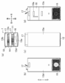
- Drawing 1 is a perspective view showing an outline of a humidifying device concerning an embodiment.
- (a) is a top view of a humidifier.
- (b) is a left side view of the humidifier.
- (c) is a front view of the humidifier.
- (d) is a right side view of the humidifier.
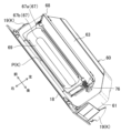
- (a) is a perspective view of the humidifying device in the second posture.
- (b) is a perspective view of the humidifying device in the first posture.
- FIG. 4 is an enlarged view of the humidifying chamber in the IV-IV line cross section of FIG.
- FIG. 5 is an enlarged view of the lower part of the humidifying chamber in the VV line cross section of FIG.
- FIG. 6 is a perspective view of the tank and side door removed from the casing.
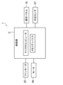
- FIG. 8 is a block diagram showing the relationship between the control unit and various devices.
- the humidifying apparatus (1) of the present embodiment is a floor-standing apparatus to be placed indoors.
- a humidifier (1) has a humidifying function and an air cleaning function. The user can select the air cleaning function only, but the air cleaning function is accompanied when the humidification function is selected.
- the humidifier (1) mainly includes a casing (10), a fan unit (U1), an air cleaning unit (U2), a humidification unit (U3), and a water supply unit (U4).
- the humidifier (1) conveys the sucked indoor air through the fan unit (U1), the air cleaning unit (U2), and the humidifying unit (U3) in order, and blows it indoors.
- a casing (10 a fan unit (U1), an air cleaning unit (U2), a humidification unit (U3), and a water supply unit (U4).
- the casing (10) is formed in a vertically long box shape.
- An air passage (AP) is formed in the vertical direction in the casing (10).
- a blowing chamber (2), an air cleaning chamber (3), and a humidifying chamber (4) are arranged in this order from bottom to top.
- the casing (10) has a top plate (11), a bottom plate (12), and four side plates (13).
- An operation panel (16) is provided on the top plate (11).
- the operation panel (16) includes a power switch for selecting operation and stop of the humidifier (1), a button for selecting execution and stop of the humidification function, and the like.
- the operation panel (16) includes a display (not shown) on which predetermined information is displayed.
- the predetermined information is, for example, the current indoor humidity, water level information in the tray (50) described later, and the like.
- "front”, “rear”, “right” and “left” indicate directions when the operation panel (16) is viewed from the front.
- the top plate (11) is provided with an air outlet (14).
- the outlet (14) is formed behind the operation panel (16).
- the outlet (14) is formed over the entire area in the left-right direction.
- the outlet (14) is provided with two flaps (17).
- Each flap (17) is formed in a horizontally long rectangle.
- the two flaps (17) are arranged side by side in the front-rear direction.
- Each flap (17) is rotatably supported by the top plate (11) and controls the opening and closing of each air outlet (14) and the wind direction.
- the four side panels (13) are a front panel (13a), a rear panel (13b), a right side panel (13c) and a left side panel (13d).
- a suction port (15) is provided in each of the lower portions of the right side panel (13c) and the left side panel (13d).
- the suction port (15) communicates with the air passage (AP) and sucks in air in the room.
- each suction port (15) is provided below the center of each side panel (13c, 13d) and substantially throughout the width direction (front-rear direction) of each side panel (13c, 13d).
- a pre-filter (not shown) is arranged in each suction port (15).
- a pre-filter is arranged to cover each suction port (15). As a result, relatively large dust and the like are collected.
- the bottom plate (12) closes the lower end of the side plate (13).
- the casing (10) is provided with a side door (18).
- the side door (18) is an example of the door portion (18) of the present disclosure.
- the side door (18) forms part of the side surface of the casing (10).
- the side door (18) forms part of the right side panel (13c).
- the side door (18) is formed in a rectangular shape, and constitutes a portion that is above the center of the right side panel (13c) and covers substantially the entire width direction (front-rear direction) of the right side panel (13c). .
- the side door (18) is configured to be openable (see Fig. 3). Specifically, the lower end of the side door (18) is rotatably supported in the casing (10). ) is slanted forward and open at the top. When fully opened, the side door (18) is inclined 25 to 45 degrees from the fully closed state (where the side door (18) is vertical).
- the state in which the side door (18) is open is the first posture (state shown in FIG. 3(b)), and the state in which the side door (18) is closed is the second posture (state in FIG. 3(a)).
- the open state means that the side door (18) is fully open
- the closed state means that the side door (18) is fully closed.
- the direction in which the side door (18) rotates from the second posture toward the first posture is defined as the first direction
- the direction in which the side door (18) rotates from the first posture to the second posture is defined as the first direction. It is called the second direction.
- the state in which the side door 18 is fully open means that the side door 18 is supported in the first posture without further turning in the first direction.
- the first posture may be a state in which at least a portion of the water supply port (67) is exposed to the outside of the casing (10) so that water can be supplied from the outside in a first water supply method described later.
- Fan unit The fan unit (U1) is placed in the blower chamber (2).
- the fan unit (U1) is arranged to face the suction port (15).
- the fan unit (U1) has a fan (21) and a fan motor (22).
- Fan (21) is a sirocco fan.
- the fan (21) is rotated by driving the fan motor (22).
- the fan (21) draws in the indoor air from each suction port (15) into the blower chamber (2), and conveys it toward the air outlet (14) to the air cleaning chamber (3) and the humidifying chamber (4) in that order. do.
- the fan (21) conveys the air in the air passage (AP) from the inlet (15) toward the outlet (14).
- the fan (21) has a variable air volume.
- the fan motor (22) is configured to have a variable rotational speed.
- the rotation speed of the fan motor (22) can be switched in a plurality of steps.
- the rotation speed of the fan motor (22) is controlled by the controller (C).
- the air cleaning unit (U2) is placed in the air cleaning room (3).
- the air cleaning unit (U2) has a dust filter (31) and a deodorizing filter (32).
- the dust collecting filter (31) and the deodorizing filter (32) are arranged so that their filter surfaces are substantially horizontal at a height position substantially in the center of the casing (10).
- the deodorizing filter (32) is arranged above the dust collecting filter (31).
- dust such as fine pollen and PM2.5 is removed by the dust collection filter (31).
- the air that has passed through the dust collection filter (31) is deodorized by a deodorizing filter (32) containing activated carbon or the like, where formaldehyde and odorous components are adsorbed or decomposed. In this way, the air is cleaned by passing through the air cleaning unit (U2).
- the humidification unit (U3) is placed in the humidification chamber (4).
- the humidification unit (U3) humidifies the air in the air passage (AP).
- the humidification unit (U3) is an example of the humidification section (U3) of the present disclosure.
- the humidification unit (U3) has an evaporation filter (41) and a frame (42).
- the vaporization filter (41) has a disk-shaped vaporization material.
- the vaporizing material is, for example, non-woven fabric. As the water adheres to the vaporization material, moisture is supplied to the air passing through the vaporization filter (41).
- the vaporization filter (41) is arranged so that the filter surface faces in the left-right direction.
- the frame (42) is made of an annular resin material.
- the vaporization filter (41) is held in the inner frame of the frame (42).
- a first shaft portion (43) is provided at the center of the circle of the frame (42).
- the first shaft (43) is connected to the motor (44) (see FIG. 4). By driving the motor (44), the frame (42) and the vaporization filter (41) rotate together. At its lowest point, the frame (42) is arranged to be submerged in water in a second tray (50b), which will be described later.
- a plurality of water scooping parts (42a) arranged along the circumferential direction are provided on the outer peripheral edge of the frame (42).
- the plurality of water fetching parts (42a) are arranged at regular intervals. As the frame (42) rotates, the water scooping portion (42a) passing through the lowest point of the frame (42) scoops up water. In this manner, the plurality of water scooping parts (42a) sequentially scoop up the water in the tray (50).
- the water scooping part (42a) discharges water toward the vaporization filter (41) when passing near the highest point of the frame (42). Water is attached to the vaporization filter (41) by the water supplied from the water scooping portion (42a). Thus, the vaporization filter (41) is configured to be supplied with water by rotation. Since the vaporization filter (41) rotates together with the frame (42), water is evenly supplied to the vaporization filter (41) from the plurality of water scooping portions (42a). Moisture is supplied (humidified) to the air as the air passes through the water-adhered area of the vaporization filter (41).
- the water supply unit (U4) is placed in the humidification chamber (4).
- the water supply unit (U4) supplies water to the humidification unit (U3).
- a water supply unit (U4) is arranged between the humidification unit (U3) and the side door (18).
- the water supply unit (U4) has a tray (50) and a tank (60).
- the tray (50) is placed in the humidification chamber (4).
- a tray (50) is placed between the humidification unit (U3) and the side door (18).
- the tray (50) stores water supplied from the tank (60).
- the tray (50) supplies water to the humidification unit (U3).
- the tray (50) has a first tray (50a) and a second tray (50b).
- the tray (50) is configured so that water in the first tray (50a) and the second tray (50b) can flow back and forth.
- the first tray (50a) is arranged below the tank (60). Water stored in the tank (60) flows into the first tray (50a). A portion of the bottom surface of the first tray (50a) is formed deep so that a float portion (51), which will be described later, is disposed thereon.
- the first tray (50a) is provided with an antibacterial section (not shown). The antibacterial part has an antibacterial material and suppresses the growth of mold and bacteria in the water in the tray (50).
- the second tray (50b) is arranged below the frame (42).
- the second tray (50b) is provided to cover the lower part of the frame (42) so that the water scooping part (42a) can scoop water.
- the second tray (50b) has a plate-like bottom (58) and two side walls (59).
- the bottom portion (58) is formed in a plate shape so that the plate surface is curved along the outer peripheral edge of the frame (42).
- Each side wall (59) is formed in a substantially semicircular shape.
- the two side walls (59) are connected to the bottom (58) facing each other.
- the second tray (50b) is provided with a bearing (59a) that rotatably supports the first shaft (43) of the frame (42).
- the bearing (59a) is provided to extend upward from the center of the side wall (59).
- the humidifier (1) of this example has a float section (51) and a water level sensor (57).
- the float portion (51) opens and closes a water supply valve (66) provided on the bottom surface of a tank (60), which will be described later.
- a water level sensor (57) detects the height position of the water surface of the tray (50).
- the float portion (51) has a float body (52), a floater (53), a magnet (56), and a contact portion (54).
- the float body (52) is provided so as to extend from the right side of the first tray (50a) toward the center.
- the floater (53) is arranged near one end of the float body (52).
- the floater (53) is hollow so as to float on the water surface and moves up and down according to the height of the water surface.
- a magnet (56) is arranged at one end of the float body (52) so as to face the inner surface of the tank (60).
- the magnet (56) moves vertically together with the float body (52).
- the contact portion (54) is provided at the other end of the float body (52).
- the contact portion (54) is arranged directly below the water supply valve (66), which will be described later.
- a second shaft portion (55) is provided on the side surface of the float body (52).
- the second shaft (55) is supported by the first tray (50a).
- the second shaft portion (55) is arranged between the floater (53) and the contact portion (54) at a position close to the contact portion (54).
- the float body (52) operates according to the seesaw principle, for example, when the floater (53) at one end of the float body (52) rises, the contact portion (54) at the other end descends.
- the water level sensor (57) detects the height position of the floater (53).
- the water level sensor (57) is, for example, a proximity sensor.
- the water level sensor (57) detects the height position of the floater (53) (the water level of the tray (50)) when the magnet (56) approaches the water level sensor (57) to a predetermined distance.
- the water level of the first tray (50a) (tray (50)) drops.
- the magnet (56) descends together with the floater (53), and when it descends to a predetermined height position, the water level sensor (57) detects that the magnet (56) is out of the predetermined distance.
- the water level sensor (57) detects that the magnet (56) is within a predetermined distance.
- the water level sensor (57) outputs an ON signal when the magnet (56) is within a detectable distance, an OFF signal when the magnet is not within a detectable distance, and the water level information of the tray (50). It is transmitted to the control unit (C), which will be described later, as a signal indicating the Upon receiving the off signal, the control section (C) displays on the display of the operation panel (16) that the amount of water stored in the tray (50) is relatively small.
- the tank (60) supplies water to the tray (50).
- the tank (60) is rotatably supported by the casing (10). Specifically, as shown in FIGS. 4-6, the tank (60) is located inside the side door (18). The tank (60) rotates as the side door (18) is opened and closed.
- the first direction is also the direction in which the tank (60) rotates from the second posture to the first posture
- the second direction is also the direction in which the tank (60) rotates from the first posture to the second posture.
- the tank (60) is configured to be removable from the casing (10).
- the tank (60) has a tank body (61), a water supply valve (66), a water supply port (67), and a lid member (68).
- the tank body (61) is shaped like a box.
- the length of the tank body (61) in the width direction (front-rear direction) is substantially the same as the length of the side door (18) in the width direction.
- the depth (horizontal direction) of the tank body (61) is slightly shorter than the depth of the first tray (50a).
- the tank (60) has a removable top cover (63). The tank body (61) opens upward when the upper lid (63) is removed.
- the tank (60) is arranged such that the first side surface (61a) of the tank (60) is along the inner surface of the side door (18). Specifically, the first side surface (61a) of the tank body (61) is arranged to face the inner surface of the side door (18).
- a circular communication hole (64) is formed near the center of the bottom surface of the tank body (61).
- the communication hole (64) provides communication between the tank (60) and the tray (50). Water in the tank (60) flows into the tray (50) through the communication hole (64).
- a cylindrical portion (65) extending downward toward the first tray (50a) is connected to the communication hole (64).
- the bottom surface of the tank body (61) is inclined so that water flows toward the communication hole (64).
- a water supply valve (66) is provided in the communication hole (64). The water supply valve (66) opens and closes the communication hole (64).
- the water supply valve (66) is an example of the opening/closing mechanism (66) of the present disclosure.
- the water supply valve (66) communicates with the tray (50).
- the water supply valve (66) has a valve body (66a), a valve shaft (66b), a disc portion (66c), and a first spring member (66d).
- the valve body (66a) is provided so as to block the opening of the communication hole (64). Specifically, the valve body (66a) is shaped like a cone that bulges downward. The communication hole (64) is closed when the conical surface of the valve body (66a) contacts the opening edge of the communication hole (64).
- the valve shaft (66b) extends downward from the lower end of the valve body (66a).
- the valve shaft (66b) is arranged inside the tubular portion (65).
- the valve shaft (66b) can move up and down within the tubular portion (65).
- the disk portion (66c) is provided at the lower end of the valve stem (66b).
- the disk portion (66c) has a larger diameter than the valve shaft (66b).
- the disk portion (66c) is arranged directly above the contact portion (54) of the float portion (51).
- the disk portion (66c) contacts the contact portion (54) depending on the water level of the first tray (50a).
- the first spring member (66d) is arranged around the valve stem (66b). In other words, the valve shaft (66b) passes through the first spring member (66d). The first spring member (66d) biases the water supply valve (66) toward the first tray (50a). Specifically, the first spring member (66d) is fixed to the lower end of the tubular portion (65), and the lower end of the first spring member (66d) presses the disk portion (66c) downward.
- the water supply valve (66) closes the communication hole (64). (61)) is prevented from flowing out of the communication hole (64).
- the contact portion (54) of the float portion (51) pushes up the disk portion (66c) (state shown in FIG. 5)
- the water supply valve (66) rises, causing the inside of the tank (60) (the tank body ( 61)) flows out from the communication hole (64) toward the tray (50).
- the tray (50) is supplied with water when the water supply valve (66) is open, and is not supplied with water when the water supply valve (66) is closed.
- the water supply port (67) is provided in the tank (60).
- the water supply port (67) communicates with the tank (60) and supplies water into the tank (60) from the outside.
- the water supply port (67) is formed in the upper lid (63) and communicates the outside with the inside of the tank body (61).
- the opening of the water supply port (67) is formed across the width direction (front-rear direction) of the upper lid (63).
- the water supply port (67) Since the tank (60) is fixed inside the side door (18), the water supply port (67) is arranged inside the side door (18). Therefore, when the side door (18) is in the first position, the water supply port (67) is exposed to the outside of the casing (10). The water supply port (67) is housed inside the casing (10) when the side door (18) is in the second posture. As the tank (60) rotates in this way, the water supply port (67) is in the first position when supplying water, and in the second position when not supplying water.
- the water supply port (67) has an inflow port (67a) and an outflow port (67b).
- the inlet (67a) is formed at the upper end of the water inlet (67). Water from the outside flows into the inflow port (67a).
- the outflow port (67b) is formed at the lower end of the water supply port (67).
- the water that has flowed in through the inflow port (67a) flows out into the tank (60) through the outflow port (67b).
- Both the inflow port (67a) and the outflow port (67b) are formed in a rectangular shape extending in the width direction (front-rear direction) of the top cover (63).
- the water supply port (67) has an inclined surface (69) that slopes from the inlet (67a) toward the outlet (67b) so that the opening area decreases.
- the opening area of the outflow port (67b) is smaller than the opening area of the inflow port (67a).
- the lid member (68) is arranged at the water inlet (67) of the upper lid (63).
- the lid member (68) is configured to open and close the water supply port (67).
- the lid member (68) has a rectangular plate shape and is arranged to cover the inlet (67a) of the water supply port (67).
- the lid member (68) is supported so that the long side on the far side can rotate, and is configured to be opened from the front side.
- the lid member (68) is provided with a second spring member (76) that biases it in the opening direction.
- the humidifier (1) of the present embodiment has a flood control mechanism (K).
- the overflow control mechanism (K) guides water overflowing from the water supply port (67) to the tray (50).
- the flood control mechanism (K) has a passage portion (P) and a pair of guard portions (19, 19).
- the passage (P) is a gap formed between the inner surface of the side door (18) and the first side surface (61a) of the tank body (61) (see FIG. 4).
- the passage (P) has an open upper end and a lower end communicating with the first tray (50a). As a result, water overflowing from the water inlet (67) flows through the passage (P) and into the first tray (50a).
- the guard part (19) is a plate-like member.
- the guard portion (19) is provided on the inner surface of the side door (18).
- a pair of guard portions (19, 19) are provided along the passage portion (P) so as to cover both ends of the first side surface (61a).
- the pair of guard portions (19) are provided to extend vertically at both ends in the width direction (front-rear direction) of the inner surface of the side door (18).
- a gap between the guard portion (19) and the side surface of the tank body (61) communicates with the first tray (50a). As a result, water overflowing from the water supply port (67) flows inside the guard portion (19) into the first tray (50a).
- the guard (19) is an example of the wall (19) of the present disclosure.
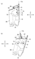
- the humidifier (1) of this embodiment includes a stopper (70).
- the stopper (70) is an example of the regulating member (70) of the present disclosure.
- the stopper (70) is a plate-like member.
- the stopper (70) is rotatably supported inside the front panel (13a) by a third shaft (73) provided on the top (see FIG. 1).
- the stopper (70) is urged by a spring member (not shown) to rotate counterclockwise (in the direction of the arrow in FIG. 7) when viewed from the front.
- a first engaging recess (71) and a second engaging recess (72) are vertically arranged in the right edge of the stopper (70).
- the first engagement recess (71) and the second engagement recess (72) are fitted with an engagement projection (75) projecting forward from the guard portion (19).
- the first engaging recess (71) is fitted with the engaging protrusion (75) (Fig. 7(a)).
- the engaging protrusion (75) moves from the first engaging recess (71) to the second while sliding on the right edge of the stopper (70). It moves to the engagement recess (72).
- the second engaging recess (72) fits into the engaging protrusion (75) (Fig. 7(b)).
- the stopper (70) restricts the tank (60) from tilting further in the first direction from the first posture.
- the humidifier (1) has a control unit (C).
- the controller (C) controls the operation of the humidifier (1).
- the control section (C) is provided with a microcomputer and a memory device for storing software for operating the microcomputer.
- the control unit (C) is connected to various devices of the humidifier (1) by wire or wirelessly.
- the controller (C) is connected to the water level sensor (57), fan motor (22), motor (44), and operation panel (16). Based on a predetermined operation command transmitted from the operation panel (16) (for example, a command to start/stop the humidifying device (1), a command to execute/stop the humidifying operation, and a command to execute/stop the drying operation), The control unit (C) controls operations of various devices.
- the humidification operation is an operation in which the indoor air that is taken in is cleaned and humidified, and then the air is blown out into the indoor space again.
- the control section (C) drives the fan motor (22) and the motor (44).
- the controller (C) controls the rotation speeds of the fan (21) and the vaporization filter (41) based on the set humidification amount and air volume.
- the indoor air sucked from the suction port (15) is conveyed from the blowing chamber (2) to the air cleaning chamber (3).
- the air conveyed to the air cleaning room (3) is cleaned by passing through the air cleaning unit (U2). After passing through the air cleaning unit (U2), the air is conveyed to the humidification chamber (4).
- the air that has flowed into the humidification chamber (4) passes through the rotating vaporization filter (41). Since the vaporization filter (41) is moistened by the water supply from the water drawing portion (42a), the air passing through the vaporization filter (41) is supplied with water.
- the passing air deprives the vaporization filter (41) of moisture, but since the vaporization filter (41) is rotating, the plurality of water scooping parts (42a) sequentially scoop up water from the second tray (50b), Water is supplied to the vaporization filter (41) one after another. Therefore, during the humidification operation, the vaporization filter (41) always contains moisture, and continues to supply moisture to the air passing through the vaporization filter (41).
- the air humidified in the humidification chamber (4) is blown into the room from the outlet (14).
- the controller (C) stops the humidification operation. This stops the humidification operation.
- the air cleaning operation described below is also performed at the same time.
- the air cleaning operation is an operation for cleaning the sucked indoor air.
- the control section (C) drives the fan motor (22).
- an air flow is generated in the air passage (AP) in which room air sucked through the suction port (15) is directed toward the blowout port (14).
- the controller (C) controls the rotation speed of the fan (21) based on the set air volume.
- the indoor air sucked from the suction port (15) is conveyed from the blowing chamber (2) to the air cleaning chamber (3).
- the air conveyed to the air cleaning room (3) passes through the dust collecting filter (31) and the deodorizing filter (32).
- the air thus purified is conveyed to the humidification chamber (4).
- the air that has flowed into the humidification chamber (4) passes through the vaporization filter (41).
- the vaporization filter (41) is stopped, so no moisture is supplied to the air passing through the vaporization filter (41).
- the air that has passed through the vaporization filter (41) is blown indoors.
- the control section (C) stops the air cleaning operation.
- the drying operation is an operation for drying the vaporization filter (41) by blowing air from the fan (21) after the operation of the humidifier (1) is stopped. Since the drying operation can dry the vaporization filter (41) in a shorter time than natural drying, the vaporization filter (41) can be prevented from mold and odor.
- the dry operation function can be switched on/off in the local settings based on the user's operation.
- the drying operation function is turned on by pressing a plurality of buttons on the operation panel (16) in predetermined order.
- the control unit (C) drives the fan motor (22) after stopping the operation of the humidifier (1) to perform the drying operation.
- the controller (C) controls the rotation speed of the fan (21) so as to minimize the air volume.
- the indoor air sucked from the suction port (15) is conveyed from the blowing chamber (2) to the air cleaning chamber (3) and then to the humidifying chamber (4).
- the air that has flowed into the humidification chamber (4) passes through the stationary vaporization filter (41). This air dries the vaporization filter (41).
- the air that has passed through the vaporization filter (41) is blown indoors.
- the control section (C) stops the drying operation.
- the lid member (68) gradually opens from the front side.
- the second engagement recess (72) of the stopper (70) fits into the engagement protrusion (75)
- the side door (18) is restricted from rotating further in the first direction and assumes the first posture. becomes.
- the lid member (68) is completely opened, and the water supply port (67) is changed from the closed state to the open state. In this manner, the lid member (68) changes so that the water inlet (67) is closed in the second position, and the water inlet (67) is open in the first position.
- Water supply is completed when a predetermined amount of water is accumulated in the tank (60).
- the engaging protrusion (75) is disengaged from the second engaging recess (72) of the stopper (70), and the side door (18) is released from the first posture. It changes to the second posture. Since the upper surface of the lid member (68) presses the right side panel (13c) and the side door (18) faces the second direction, the side door (18) is not suddenly closed. This can prevent fingers from being caught.
- the engagement protrusion (75) fits into the first engagement recess (71) of the stopper (70).
- water is supplied from the tank (60) to the tray (50).
- the contact portion (54) of the float portion (51) pushes up the disk portion (66c) of the water supply valve (66).
- This opens the water supply valve (66) and water in the tank (60) flows into the first tray (50a) through the communication hole (64) of the tank (60) (tank body (61)).
- the floater (53) rises.
- the contact portion (54) descends.
- the contact portion (54) is separated from the disk portion (66c).
- the water supply valve (66) closes and water supply from the tank (60) to the tray (50) stops.
- the side door (18) is changed from the second posture to the first posture.
- the stopper (70) is pushed downward in the first position, the second engaging recess (72) is disengaged from the engaging protrusion (75).
- This allows the tank (60) to be removed from the casing (10) together with the side door (18).
- the upper lid (63) since the upper lid (63) is removed, a predetermined amount of water can be stored in the tank body (61) in a shorter time than when water is supplied from the water supply port (67). Since the water supply valve (66) closes the communication hole (64) with the first spring member (66d), leakage of water from the tank (60) during water supply is suppressed.
- the humidifier (1) of the present embodiment communicates with a tray (50) that supplies water to the humidification unit (U3), a tank (60) that supplies water to the tray (50), and the tank (60), A water supply port (67) for supplying water into the tank (60) from the outside is provided.
- the water supply port (67) is arranged so as to be exposed to the outside of the casing (10).
- the water supply port (67) is exposed to the outside of the casing (10), so that water can be supplied directly from the outside to the tank (60) through the water supply port (67).
- the water supply port (67) of the humidifier (1) of the present embodiment has a first position exposed to the outside of the casing (10) when water is supplied, and a first position accommodated inside the casing (10) when water is not supplied. It changes to 2 postures. Thus, water can be supplied into the tank (60) by placing the water supply port (67) in the first position according to the timing of water supply. By setting the water supply port (67) to the second position when water is not supplied, the water supply port (67) is housed inside the casing (10), and dust and the like can be prevented from entering the water supply port (67).
- the humidifier (1) of the present embodiment further includes an openable and closable side door (18) forming part of the side surface of the casing (10).
- the water inlet (67) is arranged inside the side door (18), the first position is with the side door (18) open, and the second position is with the side door (18) closed. be.
- the water inlet (67) can be changed between the first posture and the second posture.
- the side door (18) is located on the side of the casing (10). Since it is not necessary to lift the , water supply work becomes easier.
- the humidifier (1) of the present embodiment further includes an openable/closable lid member (68) arranged at the water inlet (67). By opening and closing the lid member (68) so that the water supply port (67) is exposed to the outside only when water is supplied, water is prevented from splashing outside from the water supply port (67) when the lid member (68) is closed. can be suppressed.
- the lid member (68) of the humidifier (1) of the present embodiment changes so that the water inlet (67) is open in the first posture and closed in the second posture.
- the flap (17) In the second posture, when the flap (17) is open, dust in the air enters the casing (10) through the outlet (14).
- the water inlet (67) is closed by the cover member (68) in the second position, dust can be prevented from entering the water inlet (67).
- the lid member (68) of the humidifier (1) of the present embodiment is urged to keep the water inlet (67) open, and changes from the first posture to the second posture. regulate what you do. As a result, water can be supplied to the tank (60) without opening the lid member (68). Further, since the change from the first posture to the second posture is regulated, it is possible to suppress the change from the first posture to the second posture during water supply.
- the water supply port (67) of the humidifier (1) of this embodiment is provided in the tank (60).
- the tank (60) is rotatably supported by the casing (10), and the water supply port (67) changes between a first posture and a second posture as the tank (60) rotates.
- the water supply port (67) can be easily changed between the closed state and the open state simply by rotating the tank (60).
- the humidifier (1) of the present embodiment further includes a stopper (70) that prevents the tank (60) from tilting further in the first direction from the first posture.
- the stopper (70) prevents the tank (60) from inclining further forward from the first posture.
- the humidifier (1) of the present embodiment further includes an overflow suppression mechanism (K) that guides water overflowing from the water inlet (67) to the tray (50). For example, even if water overflows from the water supply port (67) during water supply, the water is guided to the tray (50) by the overflow control mechanism (K), thereby preventing water from entering the equipment inside the casing (10). can be suppressed. As a result, failure of the humidifier (1) can be suppressed.
- an overflow suppression mechanism (K) that guides water overflowing from the water inlet (67) to the tray (50). For example, even if water overflows from the water supply port (67) during water supply, the water is guided to the tray (50) by the overflow control mechanism (K), thereby preventing water from entering the equipment inside the casing (10). can be suppressed. As a result, failure of the humidifier (1) can be suppressed.
- the flood suppression mechanism (K) of the humidifier (1) of the present embodiment includes a passage (P) formed between the inner surface of the side door (18) and the first side surface (61a), the first side surface ( 61a) and a pair of guard portions (19) provided on the side door (18) along the passage portion (P) so as to cover both ends thereof.
- Water spilled between the side door (18) and the first side (61a) of the tank (60) can flow through the passage (P) into the tray (50). Water spilled on both sides of the first side surface can flow into the tray (50) along the inner surface of the guard (19).
- the tank (60) of the humidifier (1) of the present embodiment is configured to be detachable from the casing (10). Water can also be supplied by removing the tank (60). As a result, two water supply methods can be realized: a method of directly supplying water to the tank and a method of supplying water by removing the tank (60).
- the tank (60) of the humidifier (1) of this embodiment includes a water supply valve (66) communicating with the tray (50).
- the tray (50) is supplied with water when the water supply valve (66) is open, and is not supplied with water when the water supply valve (66) is closed.
- the water supply valve (66) of this embodiment is opened and closed by the contact portion (54) of the float portion (51) that moves up and down according to the water level of the tray (50).
- the water supply valve (66) opens and water is supplied from the tank (60) to the tray (50).
- the water supply valve (66) is closed to prevent water from overflowing from the tray (50).
- the water supply port (67) of the humidifier (1) of the present embodiment includes an inlet (67a) into which water flows and an outlet (67b) through which the water flowing from the inlet (67a) flows out into the tank (60). ), and the opening area of the outflow port (67b) is smaller than the opening area of the inflow port (67a).
- the water supply port (67) of the humidifier (1) may be separate from the tank (60).
- the water supply port (67) only needs to communicate the inside of the tank (60) with the outside.
- the tank (60) and the water supply port (67) may be connected via a member such as a tube. . In this case, water poured into the water supply port (67) flows into the tank (60) through the inside of the tube.
- the tank (60) of the humidifier (1) may be non-detachable from the casing (10) (fixed to the casing (10)).
- the side door (18) of the humidifier (1) may be a side-opening door.
- the side door (18) may be pivoted so that the left end or right end is open.
- the humidifier (1) has a so-called drawer structure in which the side door (18) and the tank (60) are pulled out from the casing (10) to expose the water inlet (67) to the outside.
- the air cleaning unit (U2) and the humidifying unit (U3) of the present embodiment may be configured like the air cleaning unit and humidifying element described in Patent Document 1 (eg, FIG. 3), respectively.
- the stopper (70) of the humidifier (1) may have a damper structure to prevent the side door (18) from suddenly closing when changing from the first posture to the second posture.
- this damper structure may be a gear damper.
- the gear damper has a gear formed along the left edge of the stopper (70). This gear engages with an engagement portion (not shown) fixed inside the front panel (13a) to prevent the side door (18) from suddenly changing from the first posture to the second posture. .
- the stopper (70) having such a damper structure, it is not necessary to provide the lid member (68) for maintaining the first posture as in the above embodiment.
- the overflow control mechanism (K) of the embodiment only needs to be configured to guide water overflowing from the water supply port (67) to the tray (50), and does not need to have the guard section (19).
- the present disclosure is useful for humidifiers.
- Humidifier 10 Casing 18 side door (an example of a door part) U3 Humidification unit (an example of a humidification unit) 50 trays 60 tank 61a first side 66 water supply valve (an example of an opening and closing mechanism) 67 water inlet 67a inlet 67b outlet 68 Lid member 70 stopper (an example of a regulating member)
Landscapes
- Engineering & Computer Science (AREA)
- Chemical & Material Sciences (AREA)
- Combustion & Propulsion (AREA)
- Mechanical Engineering (AREA)
- General Engineering & Computer Science (AREA)
- Air Humidification (AREA)
- Central Air Conditioning (AREA)
Priority Applications (2)
| Application Number | Priority Date | Filing Date | Title |
|---|---|---|---|
| CN202280058877.9A CN117897579B (zh) | 2021-08-31 | 2022-06-21 | 加湿装置 |
| US18/590,700 US12044432B2 (en) | 2021-08-31 | 2024-02-28 | Humidifier |
Applications Claiming Priority (2)
| Application Number | Priority Date | Filing Date | Title |
|---|---|---|---|
| JP2021140912A JP7348537B2 (ja) | 2021-08-31 | 2021-08-31 | 加湿装置 |
| JP2021-140912 | 2021-08-31 |
Related Child Applications (1)
| Application Number | Title | Priority Date | Filing Date |
|---|---|---|---|
| US18/590,700 Continuation US12044432B2 (en) | 2021-08-31 | 2024-02-28 | Humidifier |
Publications (1)
| Publication Number | Publication Date |
|---|---|
| WO2023032420A1 true WO2023032420A1 (ja) | 2023-03-09 |
Family
ID=85412075
Family Applications (1)
| Application Number | Title | Priority Date | Filing Date |
|---|---|---|---|
| PCT/JP2022/024661 Ceased WO2023032420A1 (ja) | 2021-08-31 | 2022-06-21 | 加湿装置 |
Country Status (4)
| Country | Link |
|---|---|
| US (1) | US12044432B2 (https=) |
| JP (2) | JP7348537B2 (https=) |
| CN (1) | CN117897579B (https=) |
| WO (1) | WO2023032420A1 (https=) |
Cited By (1)
| Publication number | Priority date | Publication date | Assignee | Title |
|---|---|---|---|---|
| JP2025043946A (ja) * | 2023-09-19 | 2025-04-01 | ダイキン工業株式会社 | 加湿装置 |
Citations (7)
| Publication number | Priority date | Publication date | Assignee | Title |
|---|---|---|---|---|
| JPS5541791U (https=) * | 1978-09-13 | 1980-03-18 | ||
| JPS57116026U (https=) * | 1981-01-13 | 1982-07-19 | ||
| JPH01148520U (https=) * | 1988-03-31 | 1989-10-16 | ||
| JP2000283510A (ja) * | 1999-03-30 | 2000-10-13 | Aiwa Co Ltd | タンク及び加湿器 |
| US20090158935A1 (en) * | 2005-11-01 | 2009-06-25 | Lg Electronics Inc. | Dehumidifier |
| KR20200047509A (ko) * | 2018-03-07 | 2020-05-07 | 엘지전자 주식회사 | 공기조화기 및 그 제어방법 |
| US20210088075A1 (en) * | 2018-03-16 | 2021-03-25 | Lg Electronics Inc. | Indoor unit for an air conditioner |
Family Cites Families (18)
| Publication number | Priority date | Publication date | Assignee | Title |
|---|---|---|---|---|
| JPS5933837Y2 (ja) * | 1979-10-01 | 1984-09-20 | 三菱電機株式会社 | 注液装置 |
| JPS605289Y2 (ja) * | 1980-05-09 | 1985-02-19 | 三菱電機株式会社 | 加湿装置 |
| JPS59163821U (ja) * | 1983-04-20 | 1984-11-02 | ブラザー工業株式会社 | 冷風機、加湿機などの注水装置 |
| US5765544A (en) * | 1995-06-05 | 1998-06-16 | Vigansky, Jr.; Charles E. | Flow-through humidifier for mobile home furnace |
| US6769671B2 (en) * | 2002-03-01 | 2004-08-03 | Emerson Electric Co. | Device and method for indicating the amount of water contained in a humidifier water bottle |
| JP2004101123A (ja) * | 2002-09-12 | 2004-04-02 | Mitsubishi Electric Corp | 加湿機 |
| JP2008075951A (ja) * | 2006-09-21 | 2008-04-03 | Sharp Corp | 加湿機 |
| KR100820149B1 (ko) * | 2006-11-22 | 2008-04-08 | 엘지전자 주식회사 | 공기조화기용 가습장치 및 이를 구비한 공기조화기 |
| WO2009036639A1 (en) | 2007-09-18 | 2009-03-26 | Raymond Industrial Limited | Humidifier |
| KR102054686B1 (ko) * | 2012-12-18 | 2019-12-11 | 삼성전자주식회사 | 기화식 가습기 |
| KR101504021B1 (ko) * | 2013-08-02 | 2015-03-18 | 주식회사 위닉스 | 에어 워셔 |
| KR101504020B1 (ko) * | 2013-08-02 | 2015-03-18 | 주식회사 위닉스 | 에어 워셔 |
| KR101581116B1 (ko) * | 2014-04-05 | 2015-12-29 | 엘지전자 주식회사 | 제습기 |
| JP6052242B2 (ja) * | 2014-06-19 | 2016-12-27 | ダイキン工業株式会社 | 加湿器 |
| JP6486803B2 (ja) * | 2015-09-17 | 2019-03-20 | 株式会社コロナ | 加湿装置 |
| KR102186444B1 (ko) * | 2018-01-19 | 2020-12-04 | 엘지전자 주식회사 | 가습 공기청정기 |
| CN109974109A (zh) * | 2019-04-08 | 2019-07-05 | 广东美的暖通设备有限公司 | 空气处理装置的控制方法 |
| CN212408878U (zh) * | 2020-09-15 | 2021-01-26 | 广东美的制冷设备有限公司 | 空调器 |
-
2021
- 2021-08-31 JP JP2021140912A patent/JP7348537B2/ja active Active
-
2022
- 2022-06-21 WO PCT/JP2022/024661 patent/WO2023032420A1/ja not_active Ceased
- 2022-06-21 CN CN202280058877.9A patent/CN117897579B/zh active Active
-
2023
- 2023-04-25 JP JP2023071429A patent/JP7662956B2/ja active Active
-
2024
- 2024-02-28 US US18/590,700 patent/US12044432B2/en active Active
Patent Citations (7)
| Publication number | Priority date | Publication date | Assignee | Title |
|---|---|---|---|---|
| JPS5541791U (https=) * | 1978-09-13 | 1980-03-18 | ||
| JPS57116026U (https=) * | 1981-01-13 | 1982-07-19 | ||
| JPH01148520U (https=) * | 1988-03-31 | 1989-10-16 | ||
| JP2000283510A (ja) * | 1999-03-30 | 2000-10-13 | Aiwa Co Ltd | タンク及び加湿器 |
| US20090158935A1 (en) * | 2005-11-01 | 2009-06-25 | Lg Electronics Inc. | Dehumidifier |
| KR20200047509A (ko) * | 2018-03-07 | 2020-05-07 | 엘지전자 주식회사 | 공기조화기 및 그 제어방법 |
| US20210088075A1 (en) * | 2018-03-16 | 2021-03-25 | Lg Electronics Inc. | Indoor unit for an air conditioner |
Cited By (2)
| Publication number | Priority date | Publication date | Assignee | Title |
|---|---|---|---|---|
| JP2025043946A (ja) * | 2023-09-19 | 2025-04-01 | ダイキン工業株式会社 | 加湿装置 |
| JP7733323B2 (ja) | 2023-09-19 | 2025-09-03 | ダイキン工業株式会社 | 加湿装置 |
Also Published As
| Publication number | Publication date |
|---|---|
| CN117897579A (zh) | 2024-04-16 |
| JP7662956B2 (ja) | 2025-04-16 |
| JP2023084152A (ja) | 2023-06-16 |
| US12044432B2 (en) | 2024-07-23 |
| JP2023034597A (ja) | 2023-03-13 |
| US20240200824A1 (en) | 2024-06-20 |
| CN117897579B (zh) | 2025-12-16 |
| JP7348537B2 (ja) | 2023-09-21 |
Similar Documents
| Publication | Publication Date | Title |
|---|---|---|
| JP7712760B2 (ja) | 加湿器 | |
| JP2019163898A (ja) | 加湿空気清浄装置 | |
| CN102003763A (zh) | 空气清洁加湿器 | |
| KR20200084723A (ko) | 가습기 | |
| JP2016211849A (ja) | 加湿装置及び空気清浄機 | |
| JP2023084152A (ja) | 加湿装置 | |
| JP2012013347A (ja) | 加湿装置およびそれを備えた温風機 | |
| JP5785635B2 (ja) | 加湿装置及び空気清浄機 | |
| JP4775404B2 (ja) | 調湿装置 | |
| JP6486803B2 (ja) | 加湿装置 | |
| JP2018124032A (ja) | ミスト発生装置 | |
| JP5261610B2 (ja) | 加湿装置及び空気清浄機 | |
| JP6563352B2 (ja) | 加湿機 | |
| JP6004554B2 (ja) | 加湿装置及び空気清浄機 | |
| JP4548464B2 (ja) | 調湿装置 | |
| KR20210085452A (ko) | 가습기 및 그 제어방법 | |
| JP2024101382A (ja) | 加湿器 | |
| JP2013152078A (ja) | 加湿装置及び空気清浄機 | |
| JP4640438B2 (ja) | 調湿装置 | |
| JP6105899B2 (ja) | 加湿装置 | |
| JP2011117618A (ja) | 加湿装置 | |
| JP7572632B2 (ja) | 加湿装置、及びその制御方法 | |
| JP7820644B2 (ja) | 空気処理装置 | |
| JP2012067961A (ja) | 加湿器 | |
| JP7682629B2 (ja) | 加湿器及びその制御方法 |
Legal Events
| Date | Code | Title | Description |
|---|---|---|---|
| 121 | Ep: the epo has been informed by wipo that ep was designated in this application |
Ref document number: 22864008 Country of ref document: EP Kind code of ref document: A1 |
|
| WWE | Wipo information: entry into national phase |
Ref document number: 202280058877.9 Country of ref document: CN |
|
| NENP | Non-entry into the national phase |
Ref country code: DE |
|
| 32PN | Ep: public notification in the ep bulletin as address of the adressee cannot be established |
Free format text: NOTING OF LOSS OF RIGHTS PURSUANT TO RULE 112(1) EPC (EPO FORM 1205A DATED 18/06/2024) |
|
| 122 | Ep: pct application non-entry in european phase |
Ref document number: 22864008 Country of ref document: EP Kind code of ref document: A1 |