WO2023031985A1 - 電動機 - Google Patents
電動機 Download PDFInfo
- Publication number
- WO2023031985A1 WO2023031985A1 PCT/JP2021/031657 JP2021031657W WO2023031985A1 WO 2023031985 A1 WO2023031985 A1 WO 2023031985A1 JP 2021031657 W JP2021031657 W JP 2021031657W WO 2023031985 A1 WO2023031985 A1 WO 2023031985A1
- Authority
- WO
- WIPO (PCT)
- Prior art keywords
- insulator
- rotor
- magnetic body
- electric motor
- stator
- Prior art date
- Legal status (The legal status is an assumption and is not a legal conclusion. Google has not performed a legal analysis and makes no representation as to the accuracy of the status listed.)
- Ceased
Links
Images






Classifications
-
- H—ELECTRICITY
- H02—GENERATION; CONVERSION OR DISTRIBUTION OF ELECTRIC POWER
- H02K—DYNAMO-ELECTRIC MACHINES
- H02K1/00—Details of the magnetic circuit
- H02K1/06—Details of the magnetic circuit characterised by the shape, form or construction
- H02K1/12—Stationary parts of the magnetic circuit
- H02K1/18—Means for mounting or fastening magnetic stationary parts on to, or to, the stator structures
-
- H—ELECTRICITY
- H02—GENERATION; CONVERSION OR DISTRIBUTION OF ELECTRIC POWER
- H02K—DYNAMO-ELECTRIC MACHINES
- H02K1/00—Details of the magnetic circuit
- H02K1/06—Details of the magnetic circuit characterised by the shape, form or construction
-
- H—ELECTRICITY
- H02—GENERATION; CONVERSION OR DISTRIBUTION OF ELECTRIC POWER
- H02K—DYNAMO-ELECTRIC MACHINES
- H02K3/00—Details of windings
- H02K3/32—Windings characterised by the shape, form or construction of the insulation
- H02K3/325—Windings characterised by the shape, form or construction of the insulation for windings on salient poles, such as claw-shaped poles
-
- H—ELECTRICITY
- H02—GENERATION; CONVERSION OR DISTRIBUTION OF ELECTRIC POWER
- H02K—DYNAMO-ELECTRIC MACHINES
- H02K3/00—Details of windings
- H02K3/32—Windings characterised by the shape, form or construction of the insulation
- H02K3/34—Windings characterised by the shape, form or construction of the insulation between conductors or between conductor and core, e.g. slot insulation
-
- H—ELECTRICITY
- H02—GENERATION; CONVERSION OR DISTRIBUTION OF ELECTRIC POWER
- H02K—DYNAMO-ELECTRIC MACHINES
- H02K5/00—Casings; Enclosures; Supports
- H02K5/24—Casings; Enclosures; Supports specially adapted for suppression or reduction of noise or vibrations
-
- H—ELECTRICITY
- H02—GENERATION; CONVERSION OR DISTRIBUTION OF ELECTRIC POWER
- H02K—DYNAMO-ELECTRIC MACHINES
- H02K2213/00—Specific aspects, not otherwise provided for and not covered by codes H02K2201/00 - H02K2211/00
- H02K2213/03—Machines characterised by numerical values, ranges, mathematical expressions or similar information
Definitions
- This disclosure relates to electric motors.
- the length of the stator core is longer than the length of the rotor core in the axial direction of the electric motor, there is a problem that the volume of the motor increases and the costs of the stator core and windings increase.
- the length of the stator core is shorter than the length of the rotor core in the axial direction of the electric motor, the magnetic flux flowing from the rotor into the stator core is reduced, resulting in a problem of reduced efficiency of the electric motor.
- the purpose of the present disclosure is to prevent a decrease in the efficiency of the electric motor by providing a magnetic body in the stator so as to face the rotor core, and to reduce transmitted sound in the insulator fixing the magnetic body.
- the electric motor of the present disclosure is a stator having a stator core having a yoke and teeth, a first insulator provided on the stator core, and a winding wound around the first insulator; a rotor having a rotor core and disposed inside the stator; a second insulator covering the stator; the stator core is shorter than the rotor core in the axial direction, The stator is a magnetic body fixed by the first insulator and facing the rotor core, The density of the second insulator is greater than the density of the first insulator.
- the magnetic body in the stator so as to face the rotor core, it is possible to prevent the efficiency of the electric motor from being lowered and to reduce the transmitted sound in the insulator fixing the magnetic body.
- FIG. 1 is a cross-sectional view schematically showing an electric motor according to an embodiment; FIG. It is a sectional view showing a rotor roughly.
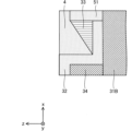
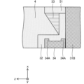
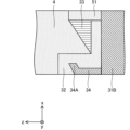
- FIG. 4 is a cross-sectional view showing another example of a rotor; 2 is an enlarged view schematically showing the structure around the magnetic body shown in FIG. 1; FIG. It is an enlarged drawing which shows roughly another structure around a magnetic body. It is an enlarged drawing which shows roughly other structure around a magnetic body. It is an enlarged drawing which shows roughly other structure around a magnetic body.
- FIG. 4 is a cross-sectional view showing another example of a magnetic body;
- FIG. 5 is a cross-sectional view showing still another example of a magnetic body; FIG.
- FIG. 5 is a cross-sectional view showing still another example of a magnetic body;
- FIG. 5 is a cross-sectional view showing still another example of a magnetic body;
- FIG. 2 is a sectional view showing the electric motor shown in FIG. 1; It is a figure which shows roughly the internal peripheral surface of a stator, and the internal peripheral surface of a 2nd insulator.
- FIG. 5 is a diagram schematically showing another example of the inner peripheral surface of the stator and the inner peripheral surface of the second insulator;
- FIG. 5 is a diagram schematically showing still another example of the inner peripheral surface of the stator and the inner peripheral surface of the second insulator;
- FIG. 4 is a cross-sectional view showing another example of a stator;
- the z-axis direction indicates a direction parallel to the axis A1 of the electric motor 1
- the x-axis direction indicates a direction orthogonal to the z-axis direction
- the y-axis direction indicates a direction orthogonal to both the z-axis direction and the x-axis direction.
- the axis A ⁇ b>1 is the center of rotation of the rotor 2 , that is, the rotation axis of the rotor 2 .
- the direction parallel to the axis A1 is also referred to as "the axial direction of the rotor 2" or simply “the axial direction”.
- the radial direction is the radial direction of the rotor 2, the stator 3, or the stator core 31, and is the direction perpendicular to the axis A1.
- the xy plane is a plane perpendicular to the axial direction.
- An arrow D1 indicates a circumferential direction about the axis A1.
- the circumferential direction of the rotor 2, stator 3, or stator core 31 is also simply referred to as "circumferential direction”.
- FIG. 1 is a cross-sectional view schematically showing an electric motor 1 according to an embodiment.
- the electric motor 1 has a rotor 2 , a stator 3 and a second insulator 4 covering the stator 3 .
- the electric motor 1 is, for example, a permanent magnet synchronous motor.
- the electric motor 1 may further have at least one wall portion 51, a circuit board 52, at least one terminal 53, and a bracket 54.
- FIG. 2 is a cross-sectional view schematically showing the rotor 2.
- the rotor 2 is rotatably arranged inside the stator 3 .
- An air gap exists between the rotor 2 and the stator 3 .
- the rotor 2 has a shaft 21 , a rotor core 22 , and first and second bearings 23 and 24 that rotatably support the shaft 21 .
- the rotor 2 may have permanent magnets for forming the magnetic poles of the rotor 2 .
- the rotor 2 is rotatable around a rotation axis (that is, axis A1).
- the shaft 21 is fixed to the rotor core 22.
- Shaft 21 is rotatably supported by first bearing 23 and second bearing 24 .
- the first bearing 23 is located outside the rotor core 22 in the axial direction. Specifically, the first bearing 23 is located on the load side of the electric motor 1 with respect to the rotor core 22 . In the example shown in FIG. 1, first bearing 23 is fixed to bracket 54 . A first bearing 23 rotatably supports the load side of the shaft 21 .
- the second bearing 24 is located outside the rotor core 22 in the axial direction. Specifically, the second bearing 24 is located on the anti-load side of the electric motor 1 with respect to the rotor core 22 . In the example shown in FIG. 1 the second bearing 24 is fixed to the second insulator 4 . A second bearing 24 rotatably supports the non-load side of the shaft 21 .
- the first bearing 23 and the second bearing 24 are rolling bearings, for example.
- vibration of the rotor 2 due to the magnetic attraction force between the rotor 2 and the stator 3 can be prevented compared to sliding bearings.
- a portion of the shaft 21 protrudes outward from the first bearing 23 in the axial direction.
- the load side of the shaft 21 protrudes outward from the first bearing 23 in the axial direction.
- the part of the shaft 21 projecting outward from the first bearing 23 is also called the power transmission part.
- the power transmission portion of the shaft 21 is provided with blades for generating airflow.
- the relationship between L1 and L2 is L1>L2. That is, the length L1 between the two bearings 23, 24 in the axial direction is longer than the length L2 of the rotor core 22 in the axial direction.
- the stator 3 includes a stator core 31, at least one first insulator 32 provided on the stator core 31, and at least one winding 33 wound around the first insulator 32. , and at least one magnetic body 34 .
- the stator core 31 has a yoke 31A extending in the circumferential direction and a plurality of teeth 31B. In FIG. 1, the boundaries between the yoke 31A and each tooth 31B are indicated by dashed lines. Each tooth 31B extends radially from the yoke 31A.
- Stator core 31 is a cylindrical core.
- the stator core 31 is formed of a plurality of magnetic steel sheets laminated in the axial direction. In this case, each of the plurality of electromagnetic steel sheets is formed into a predetermined shape by punching. These electromagnetic steel sheets are fixed to each other by caulking, welding, adhesion, or the like.
- the stator core 31 is shorter than the rotor core 22 in the axial direction.
- Each first insulator 32 insulates the stator core 31 and the magnetic bodies 34 .
- Each first insulator 32 is, for example, an insulating resin.
- Each first insulator 32 is made of, for example, polybutylene terephthalate (PBT) or polyphenylene sulfide (PPS).
- Each first insulator 32 is divided into, for example, a first portion adjacent to the magnetic body 34 and a second portion between the windings 33 and the stator core 31 .
- the first portion of each first insulator 32 fixes the magnetic body 34 and the winding 33 is wound around the second portion of each first insulator 32 .
- each first insulator 32 the first portion and the second portion of each first insulator 32 are integrated as one component. However, in each first insulator 32, the first portion and the second portion may be separated from each other.
- Each magnetic body 34 is provided so as to face the rotor core 22 on one end side of the teeth 31B in the axial direction. Each magnetic body 34 extends axially so as to face the rotor core 22 . In the example shown in FIG. 1, the magnetic bodies 34 are provided on both sides of the stator core 31 in the axial direction.
- each magnetic body 34 is in contact with the stator core 31 (specifically, the teeth 31B), but each magnetic body 34 is in contact with the stator core 31 (specifically, the teeth 31B). They don't necessarily have to be in contact. That is, each magnetic body 34 may be axially separated from the stator core 31 (specifically, the teeth 31B).
- the winding 33 is covered with the second insulator 4 .
- Each winding 33 is made of, for example, an aluminum wire.
- the second insulator 4 covers the stator 3 and insulates it.
- the second insulator 4 is, for example, insulating resin.
- the second insulator 4 is made of unsaturated polyester, for example.
- the density of the second insulator 4 is higher than the density of the first insulator 32.
- Each magnetic body 34 is fixed by the first insulator 32 .
- each magnetic body 34 is fixed by the first insulator 32 in the radial direction of the rotor 2 .
- Each magnetic body 34 is made of metal, for example.
- Each magnetic body 34 is fixed by at least one of the first insulator 32 and the second insulator 4 in the axial direction.
- FIG. 4 is an enlarged view schematically showing the structure around the magnetic body 34 shown in FIG.
- each magnetic body 34 is covered with the first insulator 32 in the axial direction.
- each magnetic body 34 is fixed by the first insulator 32 in the axial direction. That is, in the example shown in FIG. 1, each magnetic body 34 is fixed by the first insulator 32 both radially and axially. In the axial direction the first insulator 32 is fixed by the second insulator 4 .
- FIG. 5 is an enlarged view schematically showing another structure around the magnetic body 34.
- the example shown in FIG. 5 can be applied to the electric motor 1 shown in FIG.
- each magnetic body 34 is not covered by the first insulator 32 in the axial direction, and each magnetic body 34 is covered by the second insulator 4 in the axial direction. ing. Therefore, in the example shown in FIG. 5, each magnetic body 34 is fixed by the second insulator 4 in the axial direction.
- FIG. 6 is an enlarged view schematically showing still another structure around the magnetic body 34.
- the example shown in FIG. 6 can be applied to the electric motor 1 shown in FIG.
- each magnetic body 34 is covered by the first insulator 32 in the axial direction, and each magnetic body 34 is covered by the second insulator 4 in the axial direction. do not have. Therefore, in the example shown in FIG. 6, each magnetic body 34 is fixed by the first insulator 32 in the axial direction.
- FIG. 7 is an enlarged view schematically showing still another structure around the magnetic body 34.
- the example shown in FIG. 7 can be applied to the electric motor 1 shown in FIG.
- a part of each magnetic body 34 is covered with the first insulator 32 in the axial direction
- another part of each magnetic body 34 is covered with the second insulator 32 in the axial direction.
- FIG. 8 is a cross-sectional view showing another example of the magnetic body 34.
- the example shown in FIG. 8 can be applied to the electric motor 1 shown in FIG.
- At least one magnetic body 34 may have a bent portion 34A.
- the bent portion 34A protrudes toward the first insulator 32.
- the bent portion 34A is adjacent to the stator core 31 (specifically, the teeth 31B).
- the flexure 34A engages the first insulator 32 . With this configuration, the magnetic body 34 can be easily positioned.
- FIG. 9 is a cross-sectional view showing still another example of the magnetic body 34.
- the example shown in FIG. 9 can be applied to the electric motor 1 shown in FIG.
- the example shown in FIG. 9 differs from the example shown in FIG. 8 in that the bent portion 34A is separated from the stator core 31 (specifically, the teeth 31B). With this configuration, the magnetic body 34 can be easily positioned, and vibration of the magnetic body 34 in the axial direction can be reduced.
- FIG. 10 is a cross-sectional view showing still another example of the magnetic body 34.
- the example shown in FIG. 10 can be applied to the electric motor 1 shown in FIG.
- the example shown in FIG. 10 differs from the example shown in FIG. 8 in that at least one magnetic body 34 has a plurality of bent portions 34A.
- the plurality of bent portions 34A are separated from each other in the axial direction.
- Each bend 34A protrudes toward the first insulator 32 and engages with the first insulator 32 .
- the magnetic body 34 can be easily positioned, and vibration of the magnetic body 34 in the axial direction can be reduced.
- FIG. 11 is a cross-sectional view showing still another example of the magnetic body 34.
- the example shown in FIG. 11 can be applied to the electric motor 1 shown in FIG.
- the example shown in FIG. 11 is different from the example shown in FIG. 8 in that the bent portion 34A is an end portion of the magnetic body 34 in the axial direction and is bent toward the first insulator 32. .
- the magnetic body 34 can be easily positioned, and vibration of the magnetic body 34 in the axial direction can be reduced.
- FIG. 12 is a cross-sectional view showing electric motor 1 shown in FIG.
- the maximum thickness T1 of the first insulator 32 is the portion of the first insulator 32 between the second insulator 4 and the magnetic body 34 in the radial direction.
- the maximum thickness T2 of the second insulator 4 is the maximum thickness of the portion of the second insulator 4 facing the first insulator 32 in the radial direction.
- the maximum thickness T2 is thicker than the maximum thickness T1. That is, the maximum thickness T2 of the second insulator 4 facing the first insulator 32 in the radial direction is is thicker than the maximum thickness T1 of the portion between
- the maximum thickness W1 of the first insulator 32 is the maximum thickness of the portion of the first insulator 32 between the windings 33 and the stator core 31 in the axial direction.
- the maximum thickness W2 of the second insulator 4 is the maximum thickness of the portion of the second insulator 4 facing the winding 33 in the axial direction.
- the maximum thickness W2 is thicker than the maximum thickness W1. That is, in the axial direction, the maximum thickness W2 of the second insulator 4 facing the winding 33 is the maximum thickness of the portion of the first insulator 32 between the winding 33 and the stator core 31. Thicker than the thickness W1.
- the maximum thickness T3 of the second insulator 4 is the maximum thickness of the portion of the second insulator 4 facing the stator core 31 in the radial direction.
- the maximum thickness T2 of the second insulator 4 is thicker than the maximum thickness T3 of the second insulator 4 . That is, in the radial direction, the maximum thickness T2 of the portion of the second insulator 4 facing the first insulator 32 is thicker than the maximum thickness T3 of the portion where the
- Each magnetic body 34 is fixed by at least one of the first insulator 32 and the second insulator 4 in the circumferential direction of the rotor 2 .
- FIG. 13 is a diagram schematically showing the inner peripheral surface of the stator 3 and the inner peripheral surface of the second insulator 4. As shown in FIG. In the example shown in FIG. 13 , each magnetic body 34 is covered with the first insulator 32 in the circumferential direction of the rotor 2 . Therefore, in the example shown in FIG. 13 , each magnetic body 34 is fixed by the first insulator 32 in the circumferential direction of the rotor 2 .
- FIG. 14 is a diagram schematically showing another example of the inner peripheral surface of the stator 3 and the inner peripheral surface of the second insulator 4.
- the example shown in FIG. 14 can be applied to the electric motor 1 shown in FIG.
- part of each magnetic body 34 is covered with the first insulator 32 in the circumferential direction of the rotor 2 , and other parts of each magnetic body 34 are covered in the circumferential direction of the rotor 2 .
- a part is covered with a second insulator 4 . Therefore, in the example shown in FIG. 14 , each magnetic body 34 is fixed by both the first insulator 32 and the second insulator 4 in the circumferential direction of the rotor 2 .
- FIG. 15 is a diagram schematically showing still another example of the inner peripheral surface of the stator 3 and the inner peripheral surface of the second insulator 4.
- the example shown in FIG. 15 can be applied to the electric motor 1 shown in FIG.
- each magnetic body 34 is not covered with the first insulator 32 in the circumferential direction of the rotor 2, and each magnetic body 34 is covered with the second insulator 32 in the circumferential direction of the rotor 2. It is covered with insulator 4 . Therefore, in the example shown in FIG. 15 , each magnetic body 34 is fixed by the second insulator 4 in the circumferential direction of the rotor 2 .
- Each wall portion 51 (also referred to as a third insulator) is provided at an end portion of the stator core 31 in the radial direction. Each wall 51 insulates the windings 33 . Each wall portion 51 is, for example, an insulating resin.
- Terminal 53 Each terminal 53 is fixed to the wall portion 51 .
- Terminal 53 electrically connects winding 33 to circuit board 52 .
- Circuit board 52 The circuit board 52 has control elements for controlling the rotation of the rotor 2 .
- the stator 3 , wall portion 51 , circuit board 52 and terminals 53 are covered with the second insulator 4 .
- Bracket 54 A bracket 54 is fixed to the end of the second insulator 4 in the axial direction. As a result, the interior of the second insulator 4 is hermetically sealed.
- FIG. 16 is a cross-sectional view showing another example of the stator 3. As shown in FIG. In the modification, at least one magnetic body 34 is provided on the load side of the stator core 31 and is not provided on the anti-load side of the stator core 31 .
- the stator core 31 is axially shorter than the rotor core 22 , and at least one magnetic body 34 that is a component different from the stator core 31 faces the rotor core 22 .
- Each magnetic body 34 extends axially so as to face the rotor core 22 .
- the magnetic body 34 is fixed by the first insulator 32 . Therefore, even when the magnetic flux from the rotor 2 and the windings 33 flows into the magnetic body 34, the vibration of the magnetic body 34 can be reduced.
- the stator 3 is covered with the second insulator 4 , and the density of the second insulator 4 is higher than the density of the first insulator 32 .
- transmitted sound in the first insulator 32 can be reduced while the rotor 2 is rotating.
- the maximum thickness T2 of the second insulator 4 facing the first insulator 32 is the thickness of the first insulator 32 between the second insulator 4 and the magnetic material 34. If the thickness of the intermediate portion is greater than the maximum thickness T1, the transmitted sound in the first insulator 32 can be made smaller.
- the maximum thickness W2 of the second insulator 4 facing the winding 33 is the maximum thickness of the portion of the first insulator 32 between the winding 33 and the stator core 31. If it is thicker than W1, the transmitted sound in the first insulator 32 can be made smaller.
- the vibration of the winding 33 due to the current flowing through the winding 33 can be reduced.
- each winding 33 is made of aluminum wire
- the conductivity of each winding 33 can be lowered compared to copper wire. Therefore, the winding 33 made of aluminum wire can be made shorter than the winding made of copper wire, and the cost of the electric motor 1 can be reduced.
- each winding 33 is made of aluminum wire, it is weakly fixed to the first insulator 32 compared to a winding made of copper wire. However, even if each winding 33 is made of aluminum wire, the vibration of each winding 33 during rotation of the rotor 2 is reduced when the winding 33 is covered by the second insulator 4. be able to.
- Each winding 33 may be made of aluminum alloy wire instead of aluminum wire.
- Aluminum alloy wires have a higher tensile strength than aluminum wires. Therefore, when each winding 33 is made of an aluminum alloy wire, vibration of each winding 33 during rotation of the rotor 2 can be reduced as compared with a winding made of aluminum wire.
- At least one magnetic body 34 is provided on the load side of the stator core 31 and is not provided on the anti-load side of the stator core 31 . In this case, the cost of the electric motor 1 can be reduced, and the manufacture of the electric motor 1 can be facilitated.
Landscapes
- Engineering & Computer Science (AREA)
- Power Engineering (AREA)
- Iron Core Of Rotating Electric Machines (AREA)
- Motor Or Generator Frames (AREA)
- Insulation, Fastening Of Motor, Generator Windings (AREA)
Priority Applications (4)
| Application Number | Priority Date | Filing Date | Title |
|---|---|---|---|
| US18/578,161 US20240322620A1 (en) | 2021-08-30 | 2021-08-30 | Electric motor |
| JP2023544794A JP7483150B2 (ja) | 2021-08-30 | 2021-08-30 | 電動機 |
| PCT/JP2021/031657 WO2023031985A1 (ja) | 2021-08-30 | 2021-08-30 | 電動機 |
| CN202180101695.0A CN117882276A (zh) | 2021-08-30 | 2021-08-30 | 电动机 |
Applications Claiming Priority (1)
| Application Number | Priority Date | Filing Date | Title |
|---|---|---|---|
| PCT/JP2021/031657 WO2023031985A1 (ja) | 2021-08-30 | 2021-08-30 | 電動機 |
Publications (1)
| Publication Number | Publication Date |
|---|---|
| WO2023031985A1 true WO2023031985A1 (ja) | 2023-03-09 |
Family
ID=85412265
Family Applications (1)
| Application Number | Title | Priority Date | Filing Date |
|---|---|---|---|
| PCT/JP2021/031657 Ceased WO2023031985A1 (ja) | 2021-08-30 | 2021-08-30 | 電動機 |
Country Status (4)
| Country | Link |
|---|---|
| US (1) | US20240322620A1 (https=) |
| JP (1) | JP7483150B2 (https=) |
| CN (1) | CN117882276A (https=) |
| WO (1) | WO2023031985A1 (https=) |
Citations (6)
| Publication number | Priority date | Publication date | Assignee | Title |
|---|---|---|---|---|
| JP2010259140A (ja) * | 2009-04-21 | 2010-11-11 | Mitsubishi Electric Corp | 電機子 |
| EP2624420A2 (en) * | 2012-02-03 | 2013-08-07 | Samsung Electronics Co., Ltd | Motor |
| EP2706648A2 (en) * | 2012-09-11 | 2014-03-12 | Samsung Electronics Co., Ltd | Motor and washing machine having the same |
| WO2017163886A1 (ja) * | 2016-03-25 | 2017-09-28 | 三菱電機株式会社 | 回転電機用電機子 |
| WO2017179207A1 (ja) * | 2016-04-15 | 2017-10-19 | 三菱電機株式会社 | レゾルバ |
| JP6834064B1 (ja) * | 2020-01-21 | 2021-02-24 | 三菱電機株式会社 | 固定子およびこれを用いた回転電機 |
Family Cites Families (9)
| Publication number | Priority date | Publication date | Assignee | Title |
|---|---|---|---|---|
| JP5546169B2 (ja) * | 2009-07-07 | 2014-07-09 | パナソニック株式会社 | モータとそれを用いた電子機器 |
| US10164487B2 (en) * | 2013-01-28 | 2018-12-25 | Asmo Co., Ltd. | Motor, method for manufacturing magnetic plate, and method for manufacturing stator |
| US20140246929A1 (en) * | 2013-03-04 | 2014-09-04 | General Electric Company | High thermal conductivity insulation for electrical machines |
| GB2551364B (en) * | 2016-06-15 | 2023-02-01 | Time To Act Ltd | Axial flux generators |
| JP7093301B2 (ja) * | 2016-07-15 | 2022-06-29 | 三菱電機株式会社 | コンシクエントポール型ロータ、電動機、空気調和機、及びコンシクエントポール型ロータの製造方法 |
| CN111373631B (zh) * | 2017-11-29 | 2022-04-08 | 三菱电机株式会社 | 电动机、压缩机、空调机以及电动机的制造方法 |
| EP4300794A4 (en) * | 2021-02-25 | 2024-04-24 | Mitsubishi Electric Corporation | ELECTRIC MOTOR |
| JP7515690B2 (ja) * | 2021-03-18 | 2024-07-12 | 三菱電機株式会社 | 電動機 |
| JP7531723B2 (ja) * | 2021-09-06 | 2024-08-09 | 三菱電機株式会社 | 固定子、電動機及び送風機 |
-
2021
- 2021-08-30 JP JP2023544794A patent/JP7483150B2/ja active Active
- 2021-08-30 US US18/578,161 patent/US20240322620A1/en active Pending
- 2021-08-30 WO PCT/JP2021/031657 patent/WO2023031985A1/ja not_active Ceased
- 2021-08-30 CN CN202180101695.0A patent/CN117882276A/zh not_active Withdrawn
Patent Citations (6)
| Publication number | Priority date | Publication date | Assignee | Title |
|---|---|---|---|---|
| JP2010259140A (ja) * | 2009-04-21 | 2010-11-11 | Mitsubishi Electric Corp | 電機子 |
| EP2624420A2 (en) * | 2012-02-03 | 2013-08-07 | Samsung Electronics Co., Ltd | Motor |
| EP2706648A2 (en) * | 2012-09-11 | 2014-03-12 | Samsung Electronics Co., Ltd | Motor and washing machine having the same |
| WO2017163886A1 (ja) * | 2016-03-25 | 2017-09-28 | 三菱電機株式会社 | 回転電機用電機子 |
| WO2017179207A1 (ja) * | 2016-04-15 | 2017-10-19 | 三菱電機株式会社 | レゾルバ |
| JP6834064B1 (ja) * | 2020-01-21 | 2021-02-24 | 三菱電機株式会社 | 固定子およびこれを用いた回転電機 |
Also Published As
| Publication number | Publication date |
|---|---|
| US20240322620A1 (en) | 2024-09-26 |
| JP7483150B2 (ja) | 2024-05-14 |
| CN117882276A (zh) | 2024-04-12 |
| JPWO2023031985A1 (https=) | 2023-03-09 |
Similar Documents
| Publication | Publication Date | Title |
|---|---|---|
| JP6771537B2 (ja) | アキシャルギャップ型回転電機 | |
| JP5519808B2 (ja) | ステータおよびこのステータを備える回転電機 | |
| JP4665454B2 (ja) | モータ | |
| JP6832935B2 (ja) | コンシクエントポール型の回転子、電動機および空気調和機 | |
| CN109314418A (zh) | 交替极型转子、电动机及空气调节机 | |
| JP2013062901A (ja) | ステータおよびこのステータを備える回転電機 | |
| JP6545393B2 (ja) | コンシクエントポール型の回転子、電動機および空気調和機 | |
| CN108028558B (zh) | 旋转电机以及旋转电机的制造方法 | |
| CN107636937B (zh) | 旋转电机 | |
| JPWO2018016026A1 (ja) | モータ及び空気調和機 | |
| JP7483150B2 (ja) | 電動機 | |
| CN114514670B (zh) | 旋转电机及旋转电机用定子 | |
| WO2024034364A1 (ja) | コイル、ステータ及び回転電機 | |
| US20240348112A1 (en) | Electric motor, and blower | |
| JP7150171B2 (ja) | 回転電機の固定子、端子台及び回転電機 | |
| WO2023047760A1 (ja) | 電機子及びモータ | |
| JP4640851B2 (ja) | 磁石発電機 | |
| JP7653240B2 (ja) | モータ | |
| JP4771278B2 (ja) | 永久磁石形電動機およびその製造方法 | |
| JP2022123735A (ja) | ステータ及びモータ | |
| WO2022219923A1 (ja) | 回転子及び電動機 | |
| WO2024219120A1 (ja) | ステータ、電動機及びステータの製造方法 | |
| JPWO2022219923A5 (https=) | ||
| JP2025014280A (ja) | コイル、コイル組立体、平角線加工装置及び平角線加工方法 | |
| WO2022255038A1 (ja) | 回転子及び電動機 |
Legal Events
| Date | Code | Title | Description |
|---|---|---|---|
| 121 | Ep: the epo has been informed by wipo that ep was designated in this application |
Ref document number: 21955882 Country of ref document: EP Kind code of ref document: A1 |
|
| WWE | Wipo information: entry into national phase |
Ref document number: 2023544794 Country of ref document: JP |
|
| WWE | Wipo information: entry into national phase |
Ref document number: 18578161 Country of ref document: US |
|
| WWE | Wipo information: entry into national phase |
Ref document number: 202180101695.0 Country of ref document: CN |
|
| NENP | Non-entry into the national phase |
Ref country code: DE |
|
| 122 | Ep: pct application non-entry in european phase |
Ref document number: 21955882 Country of ref document: EP Kind code of ref document: A1 |