WO2023021958A1 - 被覆球状化黒鉛、リチウムイオン二次電池用負極およびリチウムイオン二次電池 - Google Patents
被覆球状化黒鉛、リチウムイオン二次電池用負極およびリチウムイオン二次電池 Download PDFInfo
- Publication number
- WO2023021958A1 WO2023021958A1 PCT/JP2022/029174 JP2022029174W WO2023021958A1 WO 2023021958 A1 WO2023021958 A1 WO 2023021958A1 JP 2022029174 W JP2022029174 W JP 2022029174W WO 2023021958 A1 WO2023021958 A1 WO 2023021958A1
- Authority
- WO
- WIPO (PCT)
- Prior art keywords
- less
- spheroidized graphite
- negative electrode
- graphite
- coated
- Prior art date
- Legal status (The legal status is an assumption and is not a legal conclusion. Google has not performed a legal analysis and makes no representation as to the accuracy of the status listed.)
- Ceased
Links
Images


Classifications
-
- C—CHEMISTRY; METALLURGY
- C01—INORGANIC CHEMISTRY
- C01B—NON-METALLIC ELEMENTS; COMPOUNDS THEREOF; METALLOIDS OR COMPOUNDS THEREOF NOT COVERED BY SUBCLASS C01C
- C01B32/00—Carbon; Compounds thereof
- C01B32/20—Graphite
- C01B32/21—After-treatment
-
- H—ELECTRICITY
- H01—ELECTRIC ELEMENTS
- H01M—PROCESSES OR MEANS, e.g. BATTERIES, FOR THE DIRECT CONVERSION OF CHEMICAL ENERGY INTO ELECTRICAL ENERGY
- H01M10/00—Secondary cells; Manufacture thereof
- H01M10/05—Accumulators with non-aqueous electrolyte
- H01M10/052—Li-accumulators
- H01M10/0525—Rocking-chair batteries, i.e. batteries with lithium insertion or intercalation in both electrodes; Lithium-ion batteries
-
- H—ELECTRICITY
- H01—ELECTRIC ELEMENTS
- H01M—PROCESSES OR MEANS, e.g. BATTERIES, FOR THE DIRECT CONVERSION OF CHEMICAL ENERGY INTO ELECTRICAL ENERGY
- H01M4/00—Electrodes
- H01M4/02—Electrodes composed of, or comprising, active material
- H01M4/13—Electrodes for accumulators with non-aqueous electrolyte, e.g. for lithium-accumulators; Processes of manufacture thereof
- H01M4/133—Electrodes based on carbonaceous material, e.g. graphite-intercalation compounds or CFx
-
- H—ELECTRICITY
- H01—ELECTRIC ELEMENTS
- H01M—PROCESSES OR MEANS, e.g. BATTERIES, FOR THE DIRECT CONVERSION OF CHEMICAL ENERGY INTO ELECTRICAL ENERGY
- H01M4/00—Electrodes
- H01M4/02—Electrodes composed of, or comprising, active material
- H01M4/36—Selection of substances as active materials, active masses, active liquids
- H01M4/362—Composites
- H01M4/366—Composites as layered products
-
- H—ELECTRICITY
- H01—ELECTRIC ELEMENTS
- H01M—PROCESSES OR MEANS, e.g. BATTERIES, FOR THE DIRECT CONVERSION OF CHEMICAL ENERGY INTO ELECTRICAL ENERGY
- H01M4/00—Electrodes
- H01M4/02—Electrodes composed of, or comprising, active material
- H01M4/36—Selection of substances as active materials, active masses, active liquids
- H01M4/58—Selection of substances as active materials, active masses, active liquids of inorganic compounds other than oxides or hydroxides, e.g. sulfides, selenides, tellurides, halogenides or LiCoFy; of polyanionic structures, e.g. phosphates, silicates or borates
- H01M4/583—Carbonaceous material, e.g. graphite-intercalation compounds or CFx
- H01M4/587—Carbonaceous material, e.g. graphite-intercalation compounds or CFx for inserting or intercalating light metals
-
- C—CHEMISTRY; METALLURGY
- C01—INORGANIC CHEMISTRY
- C01P—INDEXING SCHEME RELATING TO STRUCTURAL AND PHYSICAL ASPECTS OF SOLID INORGANIC COMPOUNDS
- C01P2004/00—Particle morphology
- C01P2004/30—Particle morphology extending in three dimensions
- C01P2004/32—Spheres
-
- C—CHEMISTRY; METALLURGY
- C01—INORGANIC CHEMISTRY
- C01P—INDEXING SCHEME RELATING TO STRUCTURAL AND PHYSICAL ASPECTS OF SOLID INORGANIC COMPOUNDS
- C01P2004/00—Particle morphology
- C01P2004/51—Particles with a specific particle size distribution
-
- C—CHEMISTRY; METALLURGY
- C01—INORGANIC CHEMISTRY
- C01P—INDEXING SCHEME RELATING TO STRUCTURAL AND PHYSICAL ASPECTS OF SOLID INORGANIC COMPOUNDS
- C01P2004/00—Particle morphology
- C01P2004/60—Particles characterised by their size
- C01P2004/61—Micrometer sized, i.e. from 1-100 micrometer
-
- C—CHEMISTRY; METALLURGY
- C01—INORGANIC CHEMISTRY
- C01P—INDEXING SCHEME RELATING TO STRUCTURAL AND PHYSICAL ASPECTS OF SOLID INORGANIC COMPOUNDS
- C01P2006/00—Physical properties of inorganic compounds
- C01P2006/12—Surface area
-
- C—CHEMISTRY; METALLURGY
- C01—INORGANIC CHEMISTRY
- C01P—INDEXING SCHEME RELATING TO STRUCTURAL AND PHYSICAL ASPECTS OF SOLID INORGANIC COMPOUNDS
- C01P2006/00—Physical properties of inorganic compounds
- C01P2006/14—Pore volume
-
- C—CHEMISTRY; METALLURGY
- C01—INORGANIC CHEMISTRY
- C01P—INDEXING SCHEME RELATING TO STRUCTURAL AND PHYSICAL ASPECTS OF SOLID INORGANIC COMPOUNDS
- C01P2006/00—Physical properties of inorganic compounds
- C01P2006/16—Pore diameter
-
- H—ELECTRICITY
- H01—ELECTRIC ELEMENTS
- H01M—PROCESSES OR MEANS, e.g. BATTERIES, FOR THE DIRECT CONVERSION OF CHEMICAL ENERGY INTO ELECTRICAL ENERGY
- H01M4/00—Electrodes
- H01M4/02—Electrodes composed of, or comprising, active material
- H01M2004/021—Physical characteristics, e.g. porosity, surface area
-
- H—ELECTRICITY
- H01—ELECTRIC ELEMENTS
- H01M—PROCESSES OR MEANS, e.g. BATTERIES, FOR THE DIRECT CONVERSION OF CHEMICAL ENERGY INTO ELECTRICAL ENERGY
- H01M4/00—Electrodes
- H01M4/02—Electrodes composed of, or comprising, active material
- H01M2004/026—Electrodes composed of, or comprising, active material characterised by the polarity
- H01M2004/027—Negative electrodes
-
- Y—GENERAL TAGGING OF NEW TECHNOLOGICAL DEVELOPMENTS; GENERAL TAGGING OF CROSS-SECTIONAL TECHNOLOGIES SPANNING OVER SEVERAL SECTIONS OF THE IPC; TECHNICAL SUBJECTS COVERED BY FORMER USPC CROSS-REFERENCE ART COLLECTIONS [XRACs] AND DIGESTS
- Y02—TECHNOLOGIES OR APPLICATIONS FOR MITIGATION OR ADAPTATION AGAINST CLIMATE CHANGE
- Y02E—REDUCTION OF GREENHOUSE GAS [GHG] EMISSIONS, RELATED TO ENERGY GENERATION, TRANSMISSION OR DISTRIBUTION
- Y02E60/00—Enabling technologies; Technologies with a potential or indirect contribution to GHG emissions mitigation
- Y02E60/10—Energy storage using batteries
Definitions
- the present invention relates to coated spheroidized graphite, negative electrodes for lithium ion secondary batteries, and lithium ion secondary batteries.
- a lithium ion secondary battery has a negative electrode, a positive electrode, and a non-aqueous electrolyte as main components. Lithium ions move between the negative electrode and the positive electrode during discharging and charging processes, thereby acting as a secondary battery. Conventionally, spheroidized graphite (spheroidized graphite) is sometimes used as a negative electrode material for lithium ion secondary batteries (Patent Document 1).
- a negative electrode material for a lithium ion secondary battery is sometimes required to have excellent cycle capacity retention.
- lithium-ion secondary batteries are expected to be widely used in automobiles (hybrid automobiles, electric automobiles, etc.) in the future. For example, electric vehicles are repeatedly charged and discharged, and the better the cycle capacity retention, the better the battery life.
- an object of the present invention is to provide coated spheroidized graphite that is excellent in cycle capacity retention when used as a negative electrode material for lithium ion secondary batteries.
- the present invention provides the following [1] to [6].
- [1] In the particle size distribution of primary particles obtained using X-ray CT, the volume ratio of primary particles having an equivalent sphere diameter of 0.8 ⁇ m or less is more than 40.0% and 70.0% or less, and spheres Contains spheroidized graphite in which the volume ratio of primary particles having an equivalent diameter of 1.5 ⁇ m or more and 3.0 ⁇ m or less is 3.0% or more and 17.0% or less, and a carbonaceous material covering the spheroidized graphite.
- the pore volume corresponding to pores with a pore diameter of 7.8 nm or more and 36.0 nm or less is 0.017 cm 3 /g or less, and the permeation mass of dibutyl phthalate is less than 0.70 g/cm 3 , coated spheroidized graphite.
- the spheroidized graphite has a volume ratio of spherical secondary particles of 3.0% or more and 26.0% or less in the particle shape distribution of the secondary particles obtained using X-ray CT, and , The coated spheroidized graphite according to the above [1], wherein the volume ratio of the rod-shaped secondary particles is 20.0% or more and 70.0% or less.
- coated spheroidized graphite that is excellent in cycle capacity retention when used as a negative electrode material for lithium ion secondary batteries.
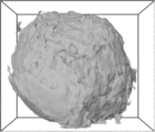
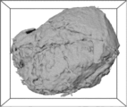
- FIG. 1B is a three-dimensional image of spherical particles observed from an angle different from that of FIG. 1A.
- FIG. 1A-B is a three-dimensional image of spherical particles observed from different angles.
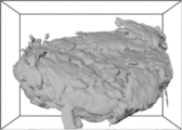
- 1A-C are three-dimensional images of spherical particles observed from different angles. It is a three-dimensional image of rod-shaped particles.
- 2B is a three-dimensional image of rod-shaped particles observed from an angle different from that of FIG. 2A.
- 2A-B are three-dimensional images of rod-shaped particles observed from different angles.
- 2A-C are three-dimensional images of rod-shaped particles observed from different angles. It is a three-dimensional image of other secondary particles.
- FIG. 2 is a cross-sectional view of an evaluation battery prepared for evaluating battery characteristics in Examples and Comparative Examples.
- the volume ratio of primary particles having an equivalent sphere diameter of 0.8 ⁇ m or less (hereinafter also referred to as “fine particles”) is 40. 0% or more and 70.0% or less, and the volume ratio of primary particles having an equivalent sphere diameter of 1.5 ⁇ m or more and 3.0 ⁇ m or less (hereinafter also referred to as “coarse particles”) is 3.0% or more and 17 0% or less of spheroidized graphite and a carbonaceous material covering the spheroidized graphite.
- the pore volume corresponding to pores having a pore diameter of 7.8 nm or more and 36.0 nm or less is 0.017 cm 3 /g or less, and the permeation mass of dibutyl phthalate is , less than 0.70 g/cm 3 .
- the decrease in cycle capacity is reduced (excellent cycle capacity retention). It is presumed that this is because, for example, expansion and contraction of the spheroidized graphite is suppressed when the fine particles and coarse particles are in the above ratio. Furthermore, when the pore volume and the permeation mass of dibutyl phthalate are within the above ranges, the cycle capacity retention is excellent for the reasons described later.
- spheroidized graphite contained in the coated spheroidized graphite of the present invention (hereinafter also referred to as “spheroidized graphite of the present invention” for convenience) will be described.
- the volume ratio of fine particles is more than 40.0% and 70.0% or less, and the volume ratio of coarse particles is 3.0% or more and 17.0% or less.
- the volume ratio of the fine particles is preferably 40.1% or more, more preferably 40.2% or more, for the reason that cycle capacity retention is more excellent.
- the volume ratio of fine particles is preferably 60.0% or less, more preferably 50.0% or less, still more preferably 45.0% or less, and particularly preferably 43.0% or less.
- the volume ratio of coarse particles is preferably 16.8% or less, more preferably 16.5% or less, and even more preferably 16.2% or less, because the cycle capacity retention is more excellent.
- the volume ratio of coarse particles is preferably 3.5% or more, more preferably 5.0% or more, even more preferably 7.0% or more, and particularly preferably 7.5% or more.
- Particle size distribution of primary particles A method for determining the particle size distribution of primary particles constituting the spheroidized graphite will be described. To understand the size of the primary particles, non-destructive and high-resolution visualization of the spheroidized graphite is required. Therefore, spheroidized graphite is observed by X-ray CT (computed tomography) using a radiation light source. More specifically, an imaging X-ray CT is performed at the SPring-8 beamline (BL24XU) under the following conditions.
- ⁇ X-ray energy 8 keV ⁇ Image resolution: 1248 (H) ⁇ 2048 (W) pixels ⁇ Execution pixel size: 68 nm/pixel ⁇ Exposure time: 0.5 seconds ⁇ Number of shots of projection image: 1200 ⁇ Deforce: 0.3 mm
- the spheroidized graphite sample is filled in a quartz glass capillary (inner diameter: about 0.1 mm) and subjected to X-ray CT. After capturing the projection image of the spheroidized graphite, it is reconstructed into a cross-sectional slice image.
- spherical particles secondary particles that are spherical in the particle shape distribution of secondary particles obtained using X-ray CT (hereinafter also referred to as “spherical particles”) ) is 3.0% or more and 26.0% or less, and the volume ratio of rod-shaped secondary particles (hereinafter also referred to as “rod-shaped particles”) is 20.0% or more and 70.0% The following are preferable.
- the volume ratio of the spherical particles is more preferably 25.8% or less, even more preferably 25.5% or less, and particularly preferably 25.2% or less, for the reason that cycle capacity retention is further improved.
- the volume ratio of spherical particles is more preferably 3.5% or more, still more preferably 5.0% or more, particularly preferably 7.0% or more, and most preferably 7.5% or more.
- the volume ratio of the rod-shaped particles is more preferably 20.5% or more, even more preferably 21.0% or more, and particularly preferably 21.5% or more, because the cycle capacity retention is further improved.
- the volume ratio of rod-shaped particles is more preferably 65.0% or less, still more preferably 60.0% or less, particularly preferably 50.0% or less, and most preferably 40.0% or less.
- Particle shape distribution of secondary particles A method for determining the particle shape distribution of secondary particles constituting the spheroidized graphite will be described. Non-destructive and high-resolution visualization of spheroidized graphite is required to understand the shape of secondary particles. Therefore, spheroidized graphite is observed by X-ray CT using a radiant light source. More specifically, projection type X-ray CT is performed under the following conditions at the SPring-8 beamline (BL24XU).
- ⁇ X-ray energy 20 keV ⁇ Image resolution: 2048 (H) ⁇ 2048 (W) pixels ⁇ Effective pixel size: 325 nm/pixel ⁇ Exposure time: 0.1 second ⁇ Number of projection images: 1800 ⁇ Distance between sample and detector: 10 mm A sample of spheroidized graphite is filled in a borosilicate glass capillary (inner diameter: about 0.6 mm) and subjected to X-ray CT. After capturing the projection image of the spheroidized graphite, it is reconstructed into a cross-sectional slice image.
- Spherical S/L ⁇ 0.5 and M/L ⁇ 0.5
- Rod-shaped S/L ⁇ 0.5 and M/L ⁇ 0.5
- a volume ratio of secondary particles classified into spheres (spherical particles) and a volume ratio of secondary particles classified into rods (rod-shaped particles) with respect to the total volume of each secondary particle are obtained.
- the shape distribution of secondary particles is obtained.
- the average secondary particle size (also simply referred to as “average particle size”) of the spheroidized graphite of the present invention is preferably 5.0 ⁇ m or more, more preferably 6.5 ⁇ m or more.
- the average particle size of the spheroidized graphite of the present invention is preferably 15.0 ⁇ m or less, more preferably 12.0 ⁇ m or less.
- the average particle size is the particle size at which the cumulative frequency of the particle size distribution obtained using a laser diffraction particle size distribution meter (LMS2000e, manufactured by Seishin Enterprise Co., Ltd.) is 50% in terms of volume percentage.
- the specific surface area of the spheroidized graphite of the present invention is preferably 5.0 m 2 /g or more, more preferably 7.0 m 2 /g or more.
- the specific surface area of the spheroidized graphite of the present invention is preferably 15.0 m 2 /g or less, more preferably 13.0 m 2 /g or less.
- the specific surface area is the BET specific surface area measured according to JIS Z 8830:2013 "Method for measuring specific surface area of powder (solid) by gas adsorption".
- the sample is pre-dried at 50 ° C., then nitrogen gas is flowed for 30 minutes, and then MONOSORB (manufactured by Quantachrome Instruments Japan LLC) is used to determine by the BET one-point method by nitrogen gas adsorption. .
- ⁇ Method for producing spheroidized graphite>> As a method for producing the spheroidized graphite of the present invention, a method of processing a raw material into spheres (spheroidization) and then heat-treating the material is preferably used.
- the raw material is graphite having a shape other than a spherical shape (including an ellipsoidal shape), for example, flake graphite.
- Graphite may be either natural graphite or artificial graphite, but natural graphite is preferred because of its high crystallinity.
- a method of mixing raw materials in the presence of a granulation aid such as an adhesive or a resin
- a method of applying mechanical external force to the raw materials without using a granulation aid a method of using both together. ; and the like.
- the method of applying a mechanical external force to the raw material without using a granulation aid is preferred. This method is described in more detail below.
- a raw material for example, flake graphite
- a pulverizer for example, flake graphite
- the raw material is spheroidized.
- grinding equipment include rotary ball mill, counter jet mill (manufactured by Hosokawa Micron Corporation), current jet (manufactured by Nisshin Engineering Co., Ltd.), hybridization system (manufactured by Nara Machinery Co., Ltd.), CF mill (manufactured by Ube Industries), mechano Fusion System (manufactured by Hosokawa Micron), Theta Composer (manufactured by Tokuju Kosakusho) and the like can be mentioned, and among them, Hybridization System (manufactured by Nara Machinery Works) is preferable.
- a plurality of crushing devices are arranged in series and the raw material continuously passes through the plurality of crushing devices. That is, it is preferable to arrange a plurality of pulverizing devices in series so that pulverization and granulation are performed in the next pulverizing device immediately after the raw material has passed through one pulverizing device.
- the number of pulverizing devices is, for example, one or more, preferably two or more, and more preferably three or more.
- the number of pulverizing devices is preferably 10 or less, more preferably 7 or less, and even more preferably 5 or less.
- the time for pulverizing and granulating the raw material (also referred to as "pulverization time" for convenience) is preferably 1 minute/unit or more, more preferably 3 minutes/unit or more, and 5 minutes/unit or more. is more preferred.
- the pulverization time in one pulverizer is preferably 60 minutes/unit or less, more preferably 50 minutes/unit or less, and even more preferably 40 minutes/unit or less.
- the product of the number of pulverizing devices and the pulverizing time in one pulverizing device is preferably 10 minutes or longer, more preferably 15 minutes or longer, and even more preferably 20 minutes or longer.
- the total pulverization time is preferably 180 minutes or less, more preferably 160 minutes or less.
- the pulverizer usually incorporates a rotor.
- the peripheral speed of the rotor in each pulverizing device is preferably 60 m/sec or less, more preferably 50 m/sec or less, and even more preferably 40 m/sec or less.
- the peripheral speed of the rotor in each pulverizing device is preferably 5 m/sec or more, more preferably 10 m/sec or more, and even more preferably 20 m/sec or more.
- the product (unit: m) of the total grinding time (unit: seconds) and the peripheral speed of the rotor (unit: m/second) is preferably 10,000 m or more, more preferably 20,000 m or more, and 30,000 m or more. More preferred. On the other hand, this product is preferably 600,000 m or less, more preferably 550,000 m or less, and even more preferably 500,000 m or less.
- the amount of raw material to be filled in each grinding device is small.
- the atmosphere for heat treatment is preferably a non-oxidizing atmosphere such as an argon atmosphere, a helium atmosphere, or a nitrogen atmosphere.
- the temperature at which the heat treatment is performed is preferably 300° C. or higher, more preferably 400° C.
- the heat treatment temperature is preferably 860° C. or lower, more preferably 800° C. or lower, still more preferably 700° C. or lower, and particularly preferably 600° C. or lower.
- the heat treatment time (heat treatment time) is preferably 0.5 hours or longer, more preferably 1 hour or longer, and more preferably 1.5 hours or longer.
- the heat treatment time is preferably 5 hours or less, more preferably 4 hours or less, and even more preferably 3 hours or less. If the heat treatment temperature is too low or the heat treatment time is too short, functional groups on the surface of the resulting spheroidized graphite may remain.
- the furnace used for the heat treatment includes, for example, a batch furnace, a rotary kiln, a roller hearth kiln, etc. From the viewpoint of productivity, the rotary kiln is preferred.
- the coated spheroidized graphite of the present invention contains a carbonaceous material that coats the spheroidized graphite of the present invention.
- the carbonaceous material is obtained, for example, by firing a carbonaceous precursor to be described later.
- the carbonaceous content in the coated spheroidized graphite of the present invention is preferably 1.0% by mass or more, more preferably 3.0% by mass or more, still more preferably 8.0% by mass or more, and 10.0% by mass or more. is particularly preferred. When the carbonaceous content is within this range, the active edge surfaces of the spheroidized graphite are easily covered, and the initial charge/discharge efficiency is excellent.
- the carbonaceous content in the coated spheroidized graphite of the present invention is preferably 30.0% by mass or less, more preferably 25.0% by mass or less, even more preferably 20.0% by mass or less, and 15.0% by mass. % or less is particularly preferred. If the content of carbonaceous matter is within this range, the amount of carbonaceous matter with relatively low discharge capacity is reduced, and the discharge capacity is excellent. In addition, when the content of the carbonaceous matter is within this range, the amount of the carbonaceous precursor used as described later is reduced, so fusion is less likely to occur during mixing and firing described later, and the finally obtained carbon The cracking and peeling of the quality are suppressed, and the initial charge-discharge efficiency is excellent.
- the average value of the entire coated spheroidized graphite is within the above range. It is not necessary for all individual coated spheroidized graphite to be within the above range, and a part of the coated spheroidized graphite may be included outside the above range.
- the carbonaceous content is determined from the amount of residual carbon after firing only the carbonaceous precursor under the same conditions as when firing the mixture of spheroidized graphite and the carbonaceous precursor.
- ⁇ Pore volume> The present inventors focused on the pore volume calculated by the DFT (Density Functional Theory) method from the nitrogen adsorption isotherm as an index that correlates with the resistance associated with lithium absorption and desorption in coated graphite.
- the present inventors have found that the pore volume corresponding to pores with a pore diameter of less than 7.8 nm is derived from amorphous carbon and hardly contributes to the resistance associated with lithium absorption and release. .
- the present inventors have clarified that the pore volume corresponding to pores with a pore diameter of 7.8 nm or more and 36.0 nm or less is a good index that correlates with resistance and, in turn, cycle capacity retention.
- the pore volume corresponding to pores having a pore diameter of 7.8 nm or more and 36.0 nm or less is 0.017 cm 3 /g or less.
- the lower limit of the pore volume V is not particularly limited, but is, for example, 0.005 cm 3 /g, preferably 0.008 cm 3 /g, more preferably 0.010 cm 3 /g, and 0.012 cm 3 /g. is more preferred.
- the pore volume corresponding to pores having a pore diameter of 2.0 nm or less is preferably 1.0 ⁇ 10 ⁇ 2 to 2.0 ⁇ 10 ⁇ 2 cm 3 /g.
- Measurement of pore volume by DFT method is based on JIS Z 8831-2 (method for measuring mesopores and macropores by gas adsorption) and JIS Z 8831-3 (method for measuring micropores by gas adsorption). demand. At this time, the measurement of the pore volume is started from a relative pressure of 5 ⁇ 10 ⁇ 2 Pa.
- the aggregate of coated spheroidized graphite is one of the factors that hinder improvement in cycle capacity retention. More specifically, it was estimated as follows. That is, if the functional group remains on the surface of the spheroidized graphite, the carbonaceous coating becomes non-uniform, and agglomerates are likely to form. At locations where agglomerates are present, the expansion and contraction of the spheroidized graphite is greater than at other locations, and the cycle capacity retention is likely to decline.
- DBP dibutyl phthalate
- the permeation mass of dibutyl phthalate is preferably small.
- the permeation mass of dibutyl phthalate in the coated spheroidized graphite of the present invention is less than 0.70 g/cm 3 , preferably 0.69 g/cm 3 or less, more preferably 0.66 g/cm 3 or less. preferable.
- the permeation mass of dibutyl phthalate in the coated spheroidized graphite of the present invention is preferably 0.40 g/cm 3 or more, more preferably 0.50 g/cm 3 or more, because cycle capacity retention is more excellent.
- the permeation mass of dibutyl phthalate is measured at room temperature using a dynamic wettability tester (6200TN, manufactured by Lesca). Specifically, 1.00 g of powdery coated spheroidized graphite is sampled, filled into a glass cylinder called a column, and one end of the column is covered with a nylon mesh and fixed with a fixing ring. After packing, the column is tapped so that the height of the powder in the column is 15 mm (filling volume: about 1.18 cm 3 ). Subsequently, dibutyl phthalate is put into the pot portion of the testing machine, and the column filled with the coated spheroidized graphite is set close to the lower end of the pot portion of the testing machine.
- a dynamic wettability tester 6200TN, manufactured by Lesca
- the pot part is raised toward the lower end of the column, and the lower end of the column is brought into contact with the dibutyl phthalate. After 600 seconds, the column is taken out and the increased mass is measured because the powder sucks up the liquid when it comes into contact with the liquid.
- the permeation mass of dibutyl phthalate (unit: g/cm 3 ) is obtained by dividing the increased mass by the filling volume. The above operation is performed 5 times in total, and the average value of the 5 times is taken as the permeated mass of dibutyl phthalate in the coated spheroidized graphite.
- the average secondary particle size (average particle size) of the coated spheroidized graphite of the present invention is preferably 5.0 ⁇ m or more, more preferably 6.5 ⁇ m or more, and even more preferably 8.0 ⁇ m or more.
- the average particle size of the coated spheroidized graphite of the present invention is preferably 15.0 ⁇ m or less, more preferably 13.5 ⁇ m or less, and even more preferably 12.0 ⁇ m or less.
- the specific surface area of the coated spheroidized graphite of the present invention is preferably 0.5 m 2 /g or more, more preferably 1.0 m 2 /g or more, and even more preferably 3.5 m 2 /g or more.
- the specific surface area of the coated spheroidized graphite of the present invention is preferably 10.0 m 2 /g or less, more preferably 7.5 m 2 /g or less, and even more preferably 6.0 m 2 /g or less.
- the method for producing the coated spheroidized graphite of the present invention is not particularly limited, but for example, a method of adding and mixing a carbonaceous precursor to the spheroidized graphite of the present invention, which is the core material, and then calcining the mixture is preferable.
- the carbonaceous precursor becomes the carbonaceous material covering the core material (spheroidized graphite) through mixing and firing. That is, coated spheroidized graphite is obtained. This method will be described in detail below.
- tar pitches and/or resins which are carbon materials that have lower crystallinity than graphite and do not become graphite crystals even when subjected to the high-temperature treatment required for graphitization.
- tar pitches include coal tar, light tar oil, medium tar oil, heavy tar oil, naphthalene oil, anthracene oil, coal tar pitch, pitch oil, mesophase pitch, oxygen-crosslinked petroleum pitch, and heavy oil.
- resins include thermoplastic resins such as polyvinyl alcohol and polyacrylic acid; thermosetting resins such as phenol resin and furan resin; and the like.
- the carbonaceous precursor does not contain resins and consists only of tar pitches.
- a carbonaceous precursor having a coal tar pitch of 80% by mass or more is suitable.
- a core material (spheroidized graphite) and a carbonaceous precursor are mixed.
- the mixing ratio is preferably such that the finally obtained coated spheroidized graphite has the carbonaceous content described above.
- the mixing method is not particularly limited as long as it can be mixed homogeneously, and a known mixing method is used. For example, a method of heating and mixing using a biaxial kneader having a heating mechanism such as a heater or a heat medium can be used.
- the atmosphere during mixing is not particularly limited, and is, for example, an air atmosphere.
- the temperature during mixing (mixing temperature) is preferably 5°C or higher, more preferably 10°C or higher, and even more preferably 25°C or higher.
- the mixing temperature is preferably 150° C. or lower, more preferably 100° C. or lower, and even more preferably 60° C. or lower.
- the mixture obtained by the above mixing is fired.
- the firing method is not particularly limited, but firing in an inert atmosphere is preferred in order to prevent oxidation during firing. At this time, it is preferable to use a tubular furnace.
- the atmosphere during firing can be exemplified by an argon atmosphere, a helium atmosphere, a nitrogen atmosphere, etc. as a non-oxidizing atmosphere.
- the temperature (firing temperature) for firing is preferably 700° C. or higher, more preferably 900° C. or higher.
- the firing temperature is preferably 2000° C. or lower, more preferably 1300° C. or lower, and even more preferably 1200° C. or lower.
- the baking time is preferably 5 minutes or longer.
- the firing time is preferably 30 hours or less.
- Various modes such as a linear temperature increase and a stepwise temperature increase in which the temperature is held at regular intervals can be adopted as the mode for raising the temperature to the firing temperature.
- pulverization is preferably not performed after firing.
- a different kind of graphite material may be adhered to, embedded in, or composited with the core material (spheroidized graphite).
- Heterogeneous graphite materials include, for example, carbonaceous or graphitic fibers; carbonaceous precursor materials such as amorphous hard carbon; organic materials; inorganic materials;
- the negative electrode for lithium ion secondary batteries of the present invention is a negative electrode for lithium ion secondary batteries containing the negative electrode material of the present invention.
- a negative electrode for a lithium ion secondary battery is also simply referred to as a “negative electrode”.
- the negative electrode of the present invention is produced according to a normal negative electrode.
- a negative electrode mixture prepared in advance by adding a binder to the negative electrode material of the present invention.
- the negative electrode mixture may contain active materials and conductive materials other than the negative electrode material of the present invention.
- the binder those exhibiting chemical and electrochemical stability with respect to the electrolyte are preferable, and examples thereof include fluorine-based resins such as polytetrafluoroethylene and polyvinylidene fluoride; polyethylene, polyvinyl alcohol, styrene-butadiene rubber, and the like. carboxymethyl cellulose; and the like, and two or more of these can be used in combination.
- the binder is usually used in a ratio of about 1 to 20% by mass in the total amount of the negative electrode mixture.
- the negative electrode material of the present invention is adjusted to a desired particle size by classification or the like. Thereafter, the negative electrode material of the present invention is mixed with a binder, and the resulting mixture is dispersed in a solvent to prepare a pasty negative electrode mixture.
- solvents include water, isopropyl alcohol, N-methylpyrrolidone, dimethylformamide and the like.
- stirrers, mixers, kneaders, kneaders and the like are used for mixing and dispersion.
- the prepared paste is applied to one side or both sides of the current collector and dried. In this way, a negative electrode mixture layer (negative electrode) is obtained which is uniformly and strongly adhered to the current collector.
- the thickness of the negative electrode mixture layer is preferably 10 to 200 ⁇ m, more preferably 20 to 100 ⁇ m. After the negative electrode mixture layer is formed, it is possible to further increase the adhesion strength between the negative electrode mixture layer (negative electrode) and the current collector by performing pressure bonding such as pressurization.
- the shape of the current collector is not particularly limited, but may be, for example, a foil shape, a mesh, or a net shape such as expanded metal. Copper, stainless steel, nickel and the like are preferable as the material of the current collector.
- the thickness of the current collector is preferably about 5 to 20 ⁇ m in the case of foil.
- the negative electrode of the present invention preferably has suppressed graphite orientation even if it has a high density.
- the degree of orientation of the negative electrode can be quantitatively evaluated by X-ray diffraction. The method is described below. First, a negative electrode (density: 1.20 g/cm 3 ) punched into a 2 cm 2 disc is pasted on a glass plate so that the negative electrode faces upward. When the sample thus prepared is irradiated with X-rays and diffracted, a plurality of diffraction peaks corresponding to the crystal planes of graphite appear.
- the orientation degree (I 004 /I 110 ) of the negative electrode of the present invention is preferably 2.0 or more, more preferably 3.0 or more, and still more preferably 4.0 or more. .
- a lithium ion secondary battery of the present invention is a lithium ion secondary battery having the negative electrode of the present invention.
- the lithium ion secondary battery of the present invention further has a positive electrode, a non-aqueous electrolyte and the like in addition to the negative electrode of the present invention.
- the lithium-ion secondary battery of the present invention is constructed, for example, by stacking a negative electrode, a non-aqueous electrolyte, and a positive electrode in this order and housing them in a battery exterior material.
- the lithium-ion secondary battery of the present invention can be arbitrarily selected from cylindrical, square, coin, button, and the like, depending on the application, mounted equipment, required charge/discharge capacity, and the like.
- ⁇ Positive electrode> It is preferable to select a material for the positive electrode (positive electrode active material) that can intercalate/deintercalate a sufficient amount of lithium.
- the positive electrode active material in addition to lithium, for example, lithium-containing compounds such as lithium - containing transition metal oxides, transition metal chalcogenides , vanadium oxides and lithium compounds thereof; M is at least one transition metal element, X is a numerical value in the range of 0 ⁇ X ⁇ 4, Y is a numerical value in the range of 0 ⁇ Y ⁇ 1) Chevrell phase compound; activated carbon; be done. Vanadium oxides are denoted by V 2 O 5 , V 6 O 13 , V 2 O 4 and V 3 O 8 .
- the lithium-containing transition metal oxide is a composite oxide of lithium and a transition metal, and may be a solid solution of lithium and two or more transition metals. Composite oxides may be used alone or in combination of two or more.
- the lithium-containing transition metal oxide is LiM 1 1-X M 2 X O 2 (wherein M 1 and M 2 are at least one transition metal element, and X is in the range of 0 ⁇ X ⁇ 1 ), or LiM 1 1-Y M 2 Y O 4 (wherein M 1 and M 2 are at least one transition metal element, and Y is a numerical value in the range of 0 ⁇ Y ⁇ 1) is indicated by
- the transition metal elements represented by M 1 and M 2 are Co, Ni, Mn, Cr, Ti, V, Fe, Zn, Al, In, Sn and the like, preferably Co, Ni, Fe, Mn and Ti.
- Lithium-containing transition metal oxides are produced by, for example, using lithium, transition metal oxides, hydroxides, salts, etc. as starting materials, mixing these starting materials according to the composition of the desired metal oxide, and exposing to 600°C in an oxygen atmosphere. It can be obtained by firing at a temperature of ⁇ 1000°C.
- the above compounds may be used alone or in combination of two or more.
- a carbon salt such as lithium carbonate can be added to the positive electrode.
- various additives such as a conductive agent and a binder can be appropriately used.
- the positive electrode is formed, for example, by applying a positive electrode mixture composed of a positive electrode active material, a binder, and a conductive agent for imparting conductivity to the positive electrode on both sides of the current collector to form a positive electrode mixture layer. is made.
- a binder the binder used for making the negative electrode can be used.
- the conductive agent known conductive agents such as graphite and carbon black are used.
- the shape of the current collector is not particularly limited, but may be foil-like or mesh-like.
- the material of the current collector is aluminum, stainless steel, nickel, or the like.
- the thickness of the current collector is preferably 10 to 40 ⁇ m.
- the positive electrode may be applied to a current collector with a paste-like positive electrode mixture, dried, and then crimped by pressing or the like.
- the nonaqueous electrolyte may be a liquid nonaqueous electrolyte (nonaqueous electrolyte liquid), or may be a polymer electrolyte such as a solid electrolyte or a gel electrolyte.
- the nonaqueous electrolyte battery is configured as a so-called lithium ion secondary battery.
- the nonaqueous electrolyte battery is configured as a polymer electrolyte battery such as a solid polymer electrolyte battery or a polymer gel electrolyte battery.
- LiPF 6 , LiBF 4 , LiAsF 6 , LiClO 4 , LiB(C 6 H 5 ), LiCl, LiBr, LiCF 3 SO 3 which are electrolyte salts used in ordinary non-aqueous electrolyte solutions, LiCH3SO3 , LiN(CF3SO2 ) 2 , LiC ( CF3SO2 ) 3 , LiN( CF3CH2OSO2 ) 2 , LiN( CF3CF2OSO2 ) 2 , LiN( HCF2CF 2 CH 2 OSO 2 ) 2 , LiN((CF 3 ) 2 CHOSO 2 ) 2 , LiB[ ⁇ C 6 H 3 (CF 3 ) 2 ⁇ ] 4 , LiAlCl 4 , LiSiF 6 and other lithium salts are used.
- the concentration of the electrolyte salt in the nonaqueous electrolyte liquid is preferably 0.1 to 5.0 mol/L, more preferably 0.5 to 3.0 mol/L.
- solvents for preparing the non-aqueous electrolyte solution include carbonates such as ethylene carbonate, propylene carbonate, dimethyl carbonate and diethyl carbonate; 1,1- or 1,2-dimethoxyethane, 1,2-diethoxyethane, Ethers such as tetrahydrofuran, 2-methyltetrahydrofuran, ⁇ -butyrolactone, 1,3-dioxolane, 4-methyl-1,3-dioxolane, anisole, diethyl ether; thioethers such as sulfolane and methylsulfolane; acetonitrile, chloronitrile, propio Nitriles such as nitrile; trimethyl borate, tetramethyl silicate, nitromethane, dimethylformamide, N-methylpyrrolidone, ethyl acetate, trimethyl orthoformate, nitrobenzene, benzoyl chloride, benzoyl bromide, tetraflu
- non-aqueous electrolyte is a polymer electrolyte such as a solid electrolyte or a gel electrolyte
- a polymer gelled with a plasticizer non-aqueous electrolyte liquid
- Polymers constituting the matrix include ether-based polymer compounds such as polyethylene oxide and crosslinked products thereof; poly(meth)acrylate-based polymer compounds; polyvinylidene fluoride, vinylidene fluoride-hexafluoropropylene copolymer, and the like. fluorine-based polymer compounds; and the like are preferably used.
- the concentration of the electrolyte salt in the non-aqueous electrolyte liquid, which is the plasticizer, is preferably 0.1 to 5.0 mol/L, more preferably 0.5 to 2.0 mol/L.
- the proportion of the plasticizer is preferably 10-90% by mass, more preferably 30-80% by mass.
- a separator can also be used in the lithium ion secondary battery of the present invention.
- the material of the separator is not particularly limited. Among these, synthetic resin microporous membranes are preferred, and polyolefin microporous membranes are more preferred in terms of thickness, membrane strength, and membrane resistance.
- a polyethylene microporous membrane, a polypropylene microporous membrane, and a composite microporous membrane of these can be preferably mentioned.
- ⁇ Example 1> ⁇ Preparation of spheroidized graphite>> Scaly natural graphite (average particle size: 8 ⁇ m) as a raw material was continuously passed through five pulverizers (hybridization system manufactured by Nara Machinery Co., Ltd.) arranged in series. In each pulverizer, the pulverization time was 5 minutes and the peripheral speed of the rotor was 25 m/sec. Thus, the raw material was spheronized by grinding and granulating. Next, the spheroidized raw material was heat-treated in a nitrogen atmosphere to obtain spheroidized graphite. The heat treatment temperature was 600° C., and the heat treatment time was 2 hours. Physical properties of the obtained spheroidized graphite (volume ratio of fine particles and coarse particles, etc.) were determined by the methods described above. The results are shown in Table 1 below.
- Coal tar pitch as a carbonaceous precursor was added to the obtained spheroidized graphite, and the mixture was heated to 50° C. and mixed for 30 minutes using a biaxial kneader.
- the carbonaceous precursor was added in such an amount that the carbonaceous matter finally obtained had the content (10% by mass) shown in Table 1 below.
- sintering was performed at 1100° C. for 10 hours under nitrogen flow (in a non-oxidizing atmosphere) at 5 L/min.
- coated spheroidized graphite in which the spheroidized graphite was coated with carbonaceous matter was obtained.
- Each physical property (average secondary particle size, etc.) of the obtained coated spheroidized graphite was obtained by the method described above. The results are shown in Table 1 below.
- the prepared negative electrode mixture paste was applied to a copper foil (thickness: 16 ⁇ m) in a uniform thickness and dried in vacuum at 90° C. to form a negative electrode mixture layer. Next, this negative electrode mixture layer was pressurized with a hand press at a pressure of 120 MPa. After that, the copper foil and the negative electrode mixture layer were punched out into a circular shape with a diameter of 15.5 mm.
- FIG. 4 is a cross-sectional view showing a button type secondary battery.
- the outer cup 1 and the outer can 3 are crimped at their peripheral edges via an insulating gasket 6 to form a sealed structure.
- a current collector 7a, a positive electrode 4, a separator 5, a negative electrode 2, and a current collector 7b are stacked in order from the inner surface of the outer can 3 toward the inner surface of the outer cup 1.
- a button type secondary battery shown in FIG. 4 was produced as follows. First, a non-aqueous electrolyte solution was prepared by dissolving LiPF 6 at a concentration of 1 mol/L in a mixed solvent of ethylene carbonate (33% by volume) and methyl ethyl carbonate (67% by volume). A polypropylene porous body (thickness: 20 ⁇ m) was impregnated with the obtained non-aqueous electrolyte solution to prepare a separator 5 impregnated with the non-aqueous electrolyte solution. Next, the produced separator 5 was sandwiched and laminated between the negative electrode 2 in close contact with the current collector 7b made of copper foil and the positive electrode 4 in close contact with the current collector 7a made of nickel net.
- Example 2 The number of pulverizing devices through which the raw material was passed was three, and in each pulverizing device, the pulverization time was 10 minutes and the peripheral speed of the rotor was 30 m/sec. Otherwise, the procedure was the same as in Example 1. The results are shown in Table 1 below.
- Example 3 The number of pulverizing devices through which the raw material was passed was two, and in each pulverizing device, the pulverization time was 10 minutes, the peripheral speed of the rotor was 30 m/sec, and the heat treatment temperature was 400°C. Otherwise, the procedure was the same as in Example 1. The results are shown in Table 1 below.
- Example 4 The number of pulverizing devices through which the raw material was passed was two, and in each pulverizing device, the pulverization time was 10 minutes, the peripheral speed of the rotor was 40 m/sec, and the heat treatment temperature was 500°C. Otherwise, the procedure was the same as in Example 1. The results are shown in Table 1 below.
- Example 5 The number of pulverizing devices through which the raw material was passed was two, and in each pulverizing device, the pulverization time was 15 minutes, the peripheral speed of the rotor was 50 m/sec, and the heat treatment temperature was 400°C. Otherwise, the procedure was the same as in Example 1. The results are shown in Table 1 below.
- Example 6 The number of pulverizing devices through which the raw material was passed was three, and in each pulverizing device, the pulverization time was 6 minutes and the peripheral speed of the rotor was 40 m/sec. Otherwise, the procedure was the same as in Example 1. The results are shown in Table 1 below.
- Example 7 The number of pulverizing devices through which the raw material was passed was 5, and in each pulverizing device, the pulverization time was 30 minutes, the peripheral speed of the rotor was 50 m/sec, and the heat treatment temperature was 400°C. Otherwise, the procedure was the same as in Example 1. The results are shown in Table 1 below.
- Example 8> The number of pulverizing devices through which the raw material passes was set to 5, and in each pulverizing device, the pulverization time was set to 10 minutes, the peripheral speed of the rotor was set to 50 m/sec, and the heat treatment temperature was set to 400°C. Otherwise, the procedure was the same as in Example 1. The results are shown in Table 1 below.
- Example 9 The heat treatment temperature for obtaining spheroidized graphite was set to 850°C. Otherwise, the procedure was the same as in Example 1. The results are shown in Table 2 below.
- the volume ratio of fine particles is more than 40.0% and 70.0% or less
- the volume ratio of coarse particles is 3.0% or more and 17.0% or less
- the pores Examples 1 to 9, which have a volume of 0.017 cm 3 /g or less and a permeation mass of dibutyl phthalate of less than 0.70 g/cm 3 are higher than Comparative Examples 1 to 12, which do not satisfy at least one of these conditions. , the cycle capacity retention was good.
Landscapes
- Chemical & Material Sciences (AREA)
- Chemical Kinetics & Catalysis (AREA)
- General Chemical & Material Sciences (AREA)
- Electrochemistry (AREA)
- Engineering & Computer Science (AREA)
- Organic Chemistry (AREA)
- Inorganic Chemistry (AREA)
- Materials Engineering (AREA)
- Composite Materials (AREA)
- Geology (AREA)
- Manufacturing & Machinery (AREA)
- Life Sciences & Earth Sciences (AREA)
- General Life Sciences & Earth Sciences (AREA)
- Carbon And Carbon Compounds (AREA)
- Battery Electrode And Active Subsutance (AREA)
Priority Applications (7)
| Application Number | Priority Date | Filing Date | Title |
|---|---|---|---|
| CN202280007046.9A CN116368635B (zh) | 2021-08-17 | 2022-07-28 | 包覆球状化石墨、锂离子二次电池用负极及锂离子二次电池 |
| KR1020237011485A KR102618399B1 (ko) | 2021-08-17 | 2022-07-28 | 피복 구상화 흑연, 리튬 이온 2차 전지용 부극 및 리튬 이온 2차 전지 |
| CA3234344A CA3234344C (en) | 2021-08-17 | 2022-07-28 | Coated spheroidized graphite, negative electrode for lithium ion secondary batteries and lithium ion secondary battery |
| US18/030,097 US11840452B2 (en) | 2021-08-17 | 2022-07-28 | Spherically-shaped coated graphite, negative electrode for lithium ion secondary battery, and lithium ion secondary battery |
| CA3229558A CA3229558A1 (en) | 2021-08-17 | 2022-07-28 | Coated spheroidized graphite, negative electrode for lithium ion secondary batteries and lithium ion secondary battery |
| JP2022569471A JP7309087B1 (ja) | 2021-08-17 | 2022-07-28 | 被覆球状化黒鉛、リチウムイオン二次電池用負極およびリチウムイオン二次電池 |
| EP22858279.7A EP4212479A4 (en) | 2021-08-17 | 2022-07-28 | COATED SPHEROIDAL GRAPHITE, NEGATIVE ELECTRODE FOR LITHIUM-ION SECONDARY BATTERIES AND LITHIUM-ION SECONDARY BATTERY |
Applications Claiming Priority (2)
| Application Number | Priority Date | Filing Date | Title |
|---|---|---|---|
| JP2021-132828 | 2021-08-17 | ||
| JP2021132828 | 2021-08-17 |
Publications (1)
| Publication Number | Publication Date |
|---|---|
| WO2023021958A1 true WO2023021958A1 (ja) | 2023-02-23 |
Family
ID=85240620
Family Applications (1)
| Application Number | Title | Priority Date | Filing Date |
|---|---|---|---|
| PCT/JP2022/029174 Ceased WO2023021958A1 (ja) | 2021-08-17 | 2022-07-28 | 被覆球状化黒鉛、リチウムイオン二次電池用負極およびリチウムイオン二次電池 |
Country Status (8)
| Country | Link |
|---|---|
| US (1) | US11840452B2 (https=) |
| EP (1) | EP4212479A4 (https=) |
| JP (1) | JP7309087B1 (https=) |
| KR (1) | KR102618399B1 (https=) |
| CN (1) | CN116368635B (https=) |
| CA (2) | CA3234344C (https=) |
| TW (1) | TWI825921B (https=) |
| WO (1) | WO2023021958A1 (https=) |
Families Citing this family (3)
| Publication number | Priority date | Publication date | Assignee | Title |
|---|---|---|---|---|
| KR102691511B1 (ko) * | 2022-05-20 | 2024-08-05 | 주식회사 엘피엔 | 신규한 조립구상흑연의 제조방법, 이를 이용하여 제조된 조립구상흑연, 및 이를 음극활물질로 포함하는 이차전지 |
| EP4345941A1 (en) * | 2022-09-30 | 2024-04-03 | LG Energy Solution, Ltd. | Negative electrode and secondary battery |
| WO2024065597A1 (zh) * | 2022-09-30 | 2024-04-04 | 宁德新能源科技有限公司 | 负极材料、二次电池和电子装置 |
Citations (6)
| Publication number | Priority date | Publication date | Assignee | Title |
|---|---|---|---|---|
| US20090196816A1 (en) * | 2008-02-06 | 2009-08-06 | Hiroshi Yamamoto | Carbon powder suitable as a negative electrode material for nonaqueous secondary batteries |
| JP2012216537A (ja) * | 2011-03-30 | 2012-11-08 | Mitsubishi Chemicals Corp | 非水系二次電池用炭素材、及び負極、並びに、非水系二次電池 |
| JP2012216545A (ja) * | 2011-03-30 | 2012-11-08 | Mitsubishi Chemicals Corp | 非水系二次電池用黒鉛粒子及びその製造方法、負極並びに非水系二次電池 |
| JP2014146607A (ja) | 2009-09-15 | 2014-08-14 | Mitsubishi Chemicals Corp | リチウムイオン二次電池用炭素材料 |
| JP2017134937A (ja) * | 2016-01-26 | 2017-08-03 | 東ソー株式会社 | リチウム二次電池用複合活物質およびその製造方法 |
| WO2021166812A1 (ja) * | 2020-02-21 | 2021-08-26 | Jfeケミカル株式会社 | 球状化黒鉛、被覆球状化黒鉛、リチウムイオン二次電池用負極およびリチウム二次電池 |
Family Cites Families (14)
| Publication number | Priority date | Publication date | Assignee | Title |
|---|---|---|---|---|
| DK2650955T3 (da) * | 2010-12-08 | 2016-02-15 | Nippon Coke & Engineering Co Ltd | Negativt elektrodemateriale til lithiumion-sekundærbatterier og fremgangsmåde til fremstilling heraf |
| JP6040022B2 (ja) | 2012-03-02 | 2016-12-07 | Jfeケミカル株式会社 | リチウムイオン二次電池用負極材料、リチウムイオン二次電池用負極およびリチウムイオン二次電池 |
| HUE038545T2 (hu) * | 2012-05-21 | 2018-10-29 | Imerys Graphite & Carbon Switzerland Ltd | Felület-módosított szén hibrid szemcsék, eljárás azok elõállítására, és alkalmazásuk |
| CN111517319A (zh) | 2013-03-26 | 2020-08-11 | 三菱化学株式会社 | 碳材料、使用该碳材料的非水系二次电池 |
| KR101343568B1 (ko) * | 2013-05-29 | 2013-12-20 | 주식회사 그라셀 | 고밀도 압축가공 팽창흑연 입자를 포함하는 복합흑연 방열재 및 그 제조 방법 |
| KR102823784B1 (ko) | 2014-07-07 | 2025-06-20 | 미쯔비시 케미컬 주식회사 | 탄소재, 탄소재의 제조 방법 및 탄소재를 사용한 비수계 2 차 전지 |
| KR101685832B1 (ko) * | 2014-07-29 | 2016-12-12 | 주식회사 엘지화학 | 흑연 2차 입자 및 이를 포함하는 리튬 이차전지 |
| JP6240586B2 (ja) * | 2014-10-28 | 2017-11-29 | Jfeケミカル株式会社 | リチウムイオン二次電池負極材料用黒鉛質粒子、リチウムイオン二次電池負極およびリチウムイオン二次電池 |
| JP6561790B2 (ja) | 2014-11-19 | 2019-08-21 | 三菱ケミカル株式会社 | 非水系二次電池用炭素材及び非水系二次電池 |
| JP6757704B2 (ja) * | 2017-08-31 | 2020-09-23 | 日本カーボン株式会社 | リチウムイオンキャパシタ用負極活物質の製造方法 |
| KR102240777B1 (ko) * | 2018-12-19 | 2021-04-14 | 주식회사 포스코 | 리튬 이차전지용 음극 활물질의 제조방법 |
| KR102475986B1 (ko) | 2019-01-17 | 2022-12-09 | 주식회사 엘지에너지솔루션 | 이차전지용 음극 활물질, 이를 포함하는 음극 및 이의 제조방법 |
| US12476252B2 (en) * | 2019-10-04 | 2025-11-18 | Lg Energy Solution, Ltd. | Globular carbon-based anode active material, method for manufacturing same, and anode and lithium secondary battery comprising same |
| CN112499624B (zh) * | 2020-11-30 | 2023-05-05 | 湖北亿纬动力有限公司 | 一种天然石墨的改性方法、改性天然石墨及应用 |
-
2022
- 2022-07-28 JP JP2022569471A patent/JP7309087B1/ja active Active
- 2022-07-28 WO PCT/JP2022/029174 patent/WO2023021958A1/ja not_active Ceased
- 2022-07-28 EP EP22858279.7A patent/EP4212479A4/en active Pending
- 2022-07-28 CA CA3234344A patent/CA3234344C/en active Active
- 2022-07-28 CA CA3229558A patent/CA3229558A1/en not_active Withdrawn
- 2022-07-28 KR KR1020237011485A patent/KR102618399B1/ko active Active
- 2022-07-28 US US18/030,097 patent/US11840452B2/en active Active
- 2022-07-28 CN CN202280007046.9A patent/CN116368635B/zh active Active
- 2022-08-16 TW TW111130741A patent/TWI825921B/zh active
Patent Citations (6)
| Publication number | Priority date | Publication date | Assignee | Title |
|---|---|---|---|---|
| US20090196816A1 (en) * | 2008-02-06 | 2009-08-06 | Hiroshi Yamamoto | Carbon powder suitable as a negative electrode material for nonaqueous secondary batteries |
| JP2014146607A (ja) | 2009-09-15 | 2014-08-14 | Mitsubishi Chemicals Corp | リチウムイオン二次電池用炭素材料 |
| JP2012216537A (ja) * | 2011-03-30 | 2012-11-08 | Mitsubishi Chemicals Corp | 非水系二次電池用炭素材、及び負極、並びに、非水系二次電池 |
| JP2012216545A (ja) * | 2011-03-30 | 2012-11-08 | Mitsubishi Chemicals Corp | 非水系二次電池用黒鉛粒子及びその製造方法、負極並びに非水系二次電池 |
| JP2017134937A (ja) * | 2016-01-26 | 2017-08-03 | 東ソー株式会社 | リチウム二次電池用複合活物質およびその製造方法 |
| WO2021166812A1 (ja) * | 2020-02-21 | 2021-08-26 | Jfeケミカル株式会社 | 球状化黒鉛、被覆球状化黒鉛、リチウムイオン二次電池用負極およびリチウム二次電池 |
Non-Patent Citations (1)
| Title |
|---|
| See also references of EP4212479A4 |
Also Published As
| Publication number | Publication date |
|---|---|
| US11840452B2 (en) | 2023-12-12 |
| EP4212479A4 (en) | 2024-07-24 |
| JP7309087B1 (ja) | 2023-07-14 |
| KR102618399B1 (ko) | 2023-12-27 |
| CA3234344A1 (en) | 2023-02-23 |
| CN116368635B (zh) | 2024-03-29 |
| EP4212479A1 (en) | 2023-07-19 |
| TW202313464A (zh) | 2023-04-01 |
| KR20230051609A (ko) | 2023-04-18 |
| CN116368635A (zh) | 2023-06-30 |
| TWI825921B (zh) | 2023-12-11 |
| CA3234344C (en) | 2025-06-10 |
| CA3229558A1 (en) | 2023-02-23 |
| US20230286806A1 (en) | 2023-09-14 |
| JPWO2023021958A1 (https=) | 2023-02-23 |
Similar Documents
| Publication | Publication Date | Title |
|---|---|---|
| JP6240586B2 (ja) | リチウムイオン二次電池負極材料用黒鉛質粒子、リチウムイオン二次電池負極およびリチウムイオン二次電池 | |
| JP5373388B2 (ja) | リチウムイオン二次電池用負極材料およびその製造方法 | |
| JP6507395B2 (ja) | 炭素質被覆黒鉛粒子、リチウムイオン二次電池用負極およびリチウムイオン二次電池 | |
| JP7309087B1 (ja) | 被覆球状化黒鉛、リチウムイオン二次電池用負極およびリチウムイオン二次電池 | |
| JP6858691B2 (ja) | リチウムイオン二次電池負極材料用炭素質被覆黒鉛質粒子の製造方法 | |
| JP2003132889A (ja) | リチウムイオン二次電池用負極材料およびその製造方法 | |
| JP6285350B2 (ja) | 炭素質被覆黒鉛粒子の製造方法およびリチウムイオン二次電池用負極材料の製造方法 | |
| JP7144625B2 (ja) | 球状化黒鉛、被覆球状化黒鉛、リチウムイオン二次電池用負極およびリチウム二次電池 | |
| JP7224562B1 (ja) | 炭素質被覆黒鉛粒子、リチウムイオン二次電池用負極およびリチウムイオン二次電池 | |
| TWI812403B (zh) | 被覆碳質的石墨粒子、鋰離子二次電池用負極及鋰離子二次電池 | |
| JP7123831B2 (ja) | リチウムイオン二次電池負極材料用炭素質被覆黒鉛質粒子の製造方法、リチウムイオン二次電池負極材料用炭素質被覆黒鉛質粒子、リチウムイオン二次電池負極およびリチウムイオン二次電池 | |
| JP7224563B1 (ja) | 炭素質被覆黒鉛粒子、リチウムイオン二次電池用負極およびリチウムイオン二次電池 | |
| TWI822252B (zh) | 被覆碳質的石墨粒子、鋰離子二次電池用負極及鋰離子二次電池 | |
| CA3229480C (en) | Carbonaceous material-coated graphite particles, negative electrode for lithium ion secondary batteries, and lithium ion secondary battery | |
| CA3229554C (en) | Carbon-coated graphite particles, negative electrode for lithium-ion secondary battery, and lithium-ion secondary battery | |
| KR20250006252A (ko) | 탄소질 피복 흑연 입자, 리튬 이온 2차 전지용 부극, 리튬 이온 2차 전지 및 탄소질 피복 흑연 입자의 제조 방법 |
Legal Events
| Date | Code | Title | Description |
|---|---|---|---|
| ENP | Entry into the national phase |
Ref document number: 2022569471 Country of ref document: JP Kind code of ref document: A |
|
| ENP | Entry into the national phase |
Ref document number: 20237011485 Country of ref document: KR Kind code of ref document: A |
|
| 121 | Ep: the epo has been informed by wipo that ep was designated in this application |
Ref document number: 22858279 Country of ref document: EP Kind code of ref document: A1 |
|
| ENP | Entry into the national phase |
Ref document number: 2022858279 Country of ref document: EP Effective date: 20230412 |
|
| WWE | Wipo information: entry into national phase |
Ref document number: 202417009721 Country of ref document: IN |
|
| WWE | Wipo information: entry into national phase |
Ref document number: 3229558 Country of ref document: CA |
|
| ENP | Entry into the national phase |
Ref document number: 3234344 Country of ref document: CA |
|
| NENP | Non-entry into the national phase |
Ref country code: DE |