WO2023008560A1 - 有機物低温分解装置 - Google Patents
有機物低温分解装置 Download PDFInfo
- Publication number
- WO2023008560A1 WO2023008560A1 PCT/JP2022/029296 JP2022029296W WO2023008560A1 WO 2023008560 A1 WO2023008560 A1 WO 2023008560A1 JP 2022029296 W JP2022029296 W JP 2022029296W WO 2023008560 A1 WO2023008560 A1 WO 2023008560A1
- Authority
- WO
- WIPO (PCT)
- Prior art keywords
- flue gas
- waste
- air
- temperature
- organic substance
- Prior art date
- Legal status (The legal status is an assumption and is not a legal conclusion. Google has not performed a legal analysis and makes no representation as to the accuracy of the status listed.)
- Ceased
Links
Images


Classifications
-
- B—PERFORMING OPERATIONS; TRANSPORTING
- B09—DISPOSAL OF SOLID WASTE; RECLAMATION OF CONTAMINATED SOIL
- B09B—DISPOSAL OF SOLID WASTE NOT OTHERWISE PROVIDED FOR
- B09B3/00—Destroying solid waste or transforming solid waste into something useful or harmless
- B09B3/40—Destroying solid waste or transforming solid waste into something useful or harmless involving thermal treatment, e.g. evaporation
-
- B—PERFORMING OPERATIONS; TRANSPORTING
- B09—DISPOSAL OF SOLID WASTE; RECLAMATION OF CONTAMINATED SOIL
- B09B—DISPOSAL OF SOLID WASTE NOT OTHERWISE PROVIDED FOR
- B09B5/00—Operations not covered by a single other subclass or by a single other group in this subclass
-
- C—CHEMISTRY; METALLURGY
- C02—TREATMENT OF WATER, WASTE WATER, SEWAGE, OR SLUDGE
- C02F—TREATMENT OF WATER, WASTE WATER, SEWAGE, OR SLUDGE
- C02F11/00—Treatment of sludge; Devices therefor
- C02F11/10—Treatment of sludge; Devices therefor by pyrolysis
-
- F—MECHANICAL ENGINEERING; LIGHTING; HEATING; WEAPONS; BLASTING
- F23—COMBUSTION APPARATUS; COMBUSTION PROCESSES
- F23G—CREMATION FURNACES; CONSUMING WASTE PRODUCTS BY COMBUSTION
- F23G5/00—Incineration of waste; Incinerator constructions; Details, accessories or control therefor
- F23G5/44—Details; Accessories
-
- F—MECHANICAL ENGINEERING; LIGHTING; HEATING; WEAPONS; BLASTING
- F23—COMBUSTION APPARATUS; COMBUSTION PROCESSES
- F23J—REMOVAL OR TREATMENT OF COMBUSTION PRODUCTS OR COMBUSTION RESIDUES; FLUES
- F23J15/00—Arrangements of devices for treating smoke or fumes
-
- F—MECHANICAL ENGINEERING; LIGHTING; HEATING; WEAPONS; BLASTING
- F23—COMBUSTION APPARATUS; COMBUSTION PROCESSES
- F23L—SUPPLYING AIR OR NON-COMBUSTIBLE LIQUIDS OR GASES TO COMBUSTION APPARATUS IN GENERAL ; VALVES OR DAMPERS SPECIALLY ADAPTED FOR CONTROLLING AIR SUPPLY OR DRAUGHT IN COMBUSTION APPARATUS; INDUCING DRAUGHT IN COMBUSTION APPARATUS; TOPS FOR CHIMNEYS OR VENTILATING SHAFTS; TERMINALS FOR FLUES
- F23L1/00—Passages or apertures for delivering primary air for combustion
Definitions
- the present invention relates to a low temperature decomposition apparatus for organic matter, and more particularly to a low temperature decomposition apparatus for organic matter that thermally decomposes waste containing organic matter at a temperature of 400°C or less.
- Incineration is often used as a method of disposing of industrial waste, household waste, and other waste containing organic matter. Since many incineration facilities incinerate at high temperatures exceeding 400° C., the generation of dioxins is a serious problem. Under such circumstances, as shown in Patent Documents 1 to 4, incinerators that carry out thermal decomposition treatment at a temperature of 400° C. or less have attracted attention.
- Patent Documents 1 to 4 What is common to Patent Documents 1 to 4 is that the air supplied at the time of burning the waste passes through a magnetic field formed by a magnetic field generating means such as a magnet, and that the amount of supplied air is limited to reduce the oxygen content. and as a result, thermal decomposition at a low temperature of 400°C or less is realized.
- Patent Document 1 As an effect of the magnetism generating means, in Patent Document 1, etc., it is expected that the oxygen in the air will be activated and the combustion state will be maintained continuously even with a small amount of air. The principle is undecided. The inventor of the present invention also confirmed that the presence or absence of the magnetism generating means causes a difference in combustion results, and believes that the magnetism generating means is essential for a low-temperature decomposition apparatus of 400° C. or less.
- Patent Document 4 proposes to separately treat this exhaust gas at a high temperature of 1300°C.
- the heating is performed using an electric heater, which causes another problem of increased power consumption.
- Patent Literature 2 discloses opening and closing an opening into which waste is thrown with a double door. With this configuration, it is possible to suppress outside air from entering the combustion chamber from the opening and exhaust gas from the combustion chamber to flow out from the opening.
- the double door structure requires a structure for opening and closing each door, which complicates the structure. It is also possible to use a means for connecting the double doors to each other so that the other door can be opened and closed in conjunction with the opening and closing of one of the doors. There is also the problem that a condition occurs in which outside air can easily enter the combustion chamber.
- the problem to be solved by the present invention is to solve the above-mentioned problems, to efficiently treat exhaust gas containing bad odors, etc. It is an object of the present invention to provide a low-temperature decomposition apparatus for organic matter that effectively suppresses the inflow of ash into a combustion chamber with a simple structure.
- the low-temperature decomposition apparatus for organic matter has the following technical features.
- a low-temperature decomposition apparatus for organic matter that thermally decomposes waste containing organic matter at a temperature of 400° C. or less, provided with magnetism generating means, and air taken in from the outside passes through a magnetic field formed by the magnetism generating means.
- a magnetic air-conditioning unit configured to perform thermal decomposition; an air chamber for introducing air from the magnetic air conditioning unit and temporarily storing the introduced air, and a plurality of channels for supplying the stored air from the air chamber toward the waste to supply is formed, and the flue gas discharged from the pyrolysis furnace is introduced, and the flue gas is provided with a flow path composed of a plurality of partition plates so that the flue gas moves while meandering.
- smoke trap means and flue gas combustion means for introducing flue gas discharged from the flue gas trap means, heating the flue gas to a temperature in the range of 800° C. to 1000° C. with a burner, and exhausting the flue gas.
- the organic matter low-temperature decomposition apparatus is provided with a flue gas temperature sensor that detects the temperature in the flow path through which the flue gas of the flue gas combustion means passes, and controls the drive of the burner.
- a control means is provided, and the control means drives and controls the burner so that the flue gas temperature sensor is in the range of 800° C. to 1000° C. before starting the pyrolysis treatment of the waste.
- the pyrolysis furnace is equipped with a combustion temperature sensor that detects the temperature of the waste or its vicinity, and controls the drive of the burner. and the control means stops driving the burner when the temperature sensor for combustion detects a range of 300°C to 400°C.
- the pyrolysis furnace has a double door that closes the opening for introducing the waste into the furnace,
- the outer door and the inner door that constitute the double door are mechanically connected to each other, the inner door closes when the outer door opens, and the inner door opens when the outer door closes, and the outer door and the inner door, a heat-resistant sheet for closing the opening is arranged, and the sheet is set so as to be able to be opened and closed while the outer door is open.
- the present invention provides a low-temperature decomposition apparatus for organic matter that thermally decomposes waste containing organic matter at a temperature of 400° C. or less, and is provided with a magnetic field generating means, wherein air taken in from the outside passes through a magnetic field formed by the magnetic field generating means.
- a magnetic air conditioning unit configured to pass through; An air chamber for introducing air from the magnetic air conditioning unit and temporarily storing the introduced air for supplying air, and a plurality of streams for supplying the stored air from the air chamber toward the waste.
- a pyrolysis furnace in which a passage is formed, and a flow path composed of a plurality of partition plates for introducing flue gas discharged from the pyrolysis furnace and moving the flue gas meanderingly.
- the exhaust gas trap means and the flue gas combustion means for introducing the flue gas discharged from the flue gas trap means, heating the flue gas to a temperature in the range of 800° C. to 1000° C. with a burner and exhausting it. It is possible to provide a low-temperature decomposition apparatus for organic matter that can efficiently treat exhaust gas containing odors and the like.
- the pyrolysis furnace has a double door that closes the opening for charging the waste into the furnace, and the outer door and the inner door that constitute the double door are mechanically connected to each other, and the outer door
- the inner door is closed when the door is opened, and the inner door is opened when the outer door is closed, and a heat-resistant sheet covering the opening is arranged between the outer door and the inner door, Since the sheet is set so that it can be opened and closed while the outer door is open, the exhaust gas can flow out of the combustion chamber and the outside air can flow into the combustion chamber through the opening into which the waste is thrown, with a simple structure. It is possible to provide an organic matter low-temperature decomposition apparatus that effectively suppresses the decomposition.
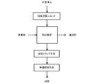
- FIG. 1 is a block diagram showing the overall configuration of an organic matter low temperature decomposition apparatus of the present invention
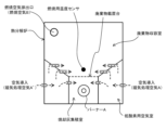
- FIG. It is a figure explaining the magnetic air-conditioning unit used for the organic substance low-temperature decomposition apparatus of this invention.
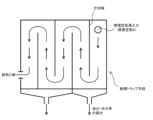
- It is a figure explaining the pyrolysis furnace used for the organic substance low-temperature decomposition apparatus of this invention.
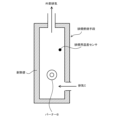
- FIG. 4 is a diagram for explaining a mechanism for opening and closing an opening installed in the upper part of the pyrolysis furnace of FIG. .
- the present invention provides a low-temperature decomposition apparatus for organic matter that thermally decomposes waste containing organic matter at a temperature of 400° C. or less.
- a "magnetic air-conditioning unit” configured to pass through a magnetic field formed by means; an air chamber for introducing air from the magnetic air conditioning unit and temporarily storing the introduced air in order to supply air to at least the lower side or side of the waste;
- a "pyrolysis furnace” in which a plurality of flow paths for supplying stored air are formed, and flue gas discharged from the pyrolysis furnace is introduced, and the flue gas moves in a meandering manner.
- a "flue gas trap means" having a flow path composed of a partition plate, and the flue gas discharged from the flue gas trap means are introduced, and the flue gas is heated to a temperature in the range of 800 ° C. to 1000 ° C. with a burner. It is characterized by having a “smoke combustion means" for exhausting the gas.
- FIG. 2 shows an example of a magnetic air conditioning unit. Specifically, a cylindrical main conduit is used, and outside air is taken in from the upper side of the main conduit, and magnetically treated air is discharged from the lower side. An electric fan is used to take in outside air, and a valve is provided to adjust the flow rate of the outside air. Valves, which may be manual or electric, are used to optimize waste combustion conditions.
- Magnetism generation means such as magnets are provided near the entrance that takes in outside air into the main conduit and near the exit that discharges the air in the main conduit.
- the magnetism generating means to be used is preferably a permanent magnet which does not consume electric power rather than an electromagnet, more preferably a neodymium magnet which can generate a strong magnetic force. It should be noted that the arrangement position of the magnets is not limited to being arranged both above and below as shown in FIG.
- a conical flow path is formed inside the main conduit so that the air flows smoothly.
- This conical flow path is not indispensable, but since the reaction proceeds in a low-oxygen state during pyrolysis at low temperature, it is required to supply the minimum necessary amount of air to the pyrolysis furnace gently and stably. be done. For this reason, even in magnetic air conditioning units, a conical flow path is formed as one method of forming a gentle but smooth air flow.
- the conical flow path also has the meaning of suppressing the air from flowing backward from the pyrolysis furnace and being discharged to the outside through the unit when the fan is stopped.
- the "waste storage chamber” is used to store the waste
- the "ash accumulation chamber” is used to collect the incineration ash that has been thermally decomposed and turned into ash (inorganic matter only). room”, and a “hypoxic air chamber” that temporarily stores air before it is supplied to the waste.
- a waste placement table is formed substantially in the center as a placement section for placing the waste, and the surrounding wall surface surrounding it is inclined so as to be lower toward the placement table.
- the mounting table is composed of a wire mesh made of metal or the like, a plurality of metal rods arranged in parallel, or the like. A wall surface surrounding the mounting table is penetrated by a plurality of pipes connecting to the hypoxic air chamber.
- FIG. 4(a) shows a state in which the outer door is opened and the inner door is closed.
- the outer door rotates in the direction of arrow ⁇ , and the rotation is performed by applying a force to pull up the outer door in the direction of arrow F.
- the force of arrow F can be gradually reduced, allowing the door to close under its own weight.
- the inner door is configured to be rotatable in the direction of arrow ⁇ . Further, the inner door is connected to the connecting means, and when the outer door is lifted as shown in FIG. 4A, the inner door is also lifted to close the opening of the wall surface (thick line portion) of the furnace body. Conversely, when the outer door is pulled down so as to block the opening, the inner door is also pulled down to open the opening as shown in FIG. 4(b).
- the connecting means is not limited to the one shown in FIG. 4, and techniques known to those skilled in the art can be applied.
- the waste is placed on the upper side of the inner door in the state shown in FIG. 4(a), and the waste is thrown into the furnace in the state shown in FIG. 4(b).
- both the outer door and the inner door are in a half-open state in the intermediate state between FIGS. 4(a) and (b).
- both the outer door and the inner door are in a half-open state in the intermediate state between FIGS. 4(a) and (b).
- the combustion air in the furnace leaks directly to the outside, but also a large amount of air is supplied to the waste that is being thermally decomposed under low oxygen conditions.
- the pyrolysis reaction will change.
- a heat-resistant sheet is placed to block the opening.
- the heat-resistant sheet is preferably made of a flame-retardant material that can withstand heat of at least 400° C. or more and that combustion in the furnace does not spread to the sheet.
- a flame-retardant material that can withstand heat of at least 400° C. or more and that combustion in the furnace does not spread to the sheet.
- the "ash collection room” stores the incineration ash that falls through the gaps in the mounting table.
- the accumulated incineration ash is discharged outside through a door (not shown) leading to an accumulation chamber installed on the side wall of the furnace body.
- the incineration ash remaining on the mounting table is discharged through an opening for throwing in waste or through another opening/closing door provided on the side wall of the furnace body.
- the incinerated ash accumulation chamber is equipped with a burner A that supplies pilot light for burning waste.
- a burner A that supplies pilot light for burning waste.
- gas type or oil type burner can be used in the same manner as the burner B used in the exhaust gas combustion means described later.
- an oil burner using kerosene can be used easily.
- the burner in the accumulation chamber can be pulled out of the furnace and removed from the accumulation chamber, if necessary, when the ignition (combustion start) of the waste is completed.
- the "low-oxygen air chamber” is to prevent the magnetic processing air from being forcibly blown directly to the waste by the fan of the magnetic air conditioning unit or the like. Thermal decomposition of the waste proceeds slowly under low oxygen conditions. It is, for example, like a slow burning going on in the ashes of a hearth or a brazier. Therefore, it is necessary to supply the waste with only the amount of air required for the reaction.
- the magnetically treated air is temporarily stored in this air chamber, and the air in the air chamber is supplied to the waste with a natural flow that supplements the air that rises due to the heat of the waste.
- the air from the air chamber not only directly enters the waste storage chamber, but also enters the incineration ash accumulation chamber once and is supplied to the waste through the clearance of the mounting table.
- the "flue gas trap means" is equipment for processing the combustion air B discharged from the discharge port provided on the upper side of the pyrolysis furnace in FIG. If the waste is completely combusted, there is no particular problem, but if the combustion is insufficient, the combustion air may contain oil or the like. As shown in FIG. 5, a plurality of partition plates are arranged in a staggered manner so that the combustion air (exhaust smoke) moves meanderingly.
- Combustion air contacts the partition plate and is cooled, and oil and moisture in the air adhere to the partition plate. Oil and the like adhering to the partition plate moves downward under its own weight and is discharged to the outside using a drain pipe. Although it is preferable to separate more oil and the like from the combustion air by this exhaust gas trap means, even if oil and the like remains in the air, if the amount is small, it can be completely burned by the flue gas combustion means in the latter stage. is possible.
- Another purpose of providing this flue gas trap means is to prevent the flame of the burner from flowing back through the exhaust route and entering the pyrolysis furnace because the burner is used in the flue gas combustion means of the latter stage. Because.
- the "flue gas combustion means” heats the exhaust gas at a high temperature and thermally decomposes the odor and residual oil contained in the exhaust gas.
- the wall surface of the flue gas combustion means is composed of a highly heat-resistant and fire-resistant wall made by stacking refractory bricks or the like.
- a burner B is arranged inside, and the temperature of the flow path through which the exhaust gas passes is set to be maintained within the range of 800°C to 1000°C.
- the temperature of the flow path can be detected by a smoke exhaust temperature sensor. By using a burner, the inside of the flow path can be heated more efficiently than the electric heater of Patent Document 4, and the thermal efficiency is also high.
- the flue gas combustion means can always be maintained at a predetermined temperature to completely pyrolyze all the combustion air discharged from the pyrolysis furnace, but this requires frequent operation of the burner B. is required, and the energy consumption is enormous. Moreover, when an oil burner is used, the amount of carbon dioxide emitted increases, which poses many environmental problems.
- control means for controlling the driving of the burner B is provided.
- the on/off or strong/weak driving of the burner is controlled so that the temperature detected by the temperature sensor for exhaust smoke is within the range of 800°C to 1000°C.
- the burner is driven and controlled so that the temperature sensor reaches a predetermined temperature (range of 800 ° C. to 1000 ° C.), and the flow path of the exhaust gas is maintained at a high temperature.
- a combustion temperature sensor that detects the temperature of the waste or its vicinity detects a range of 300 ° C to 400 ° C, and when the low temperature decomposition reaction has started stably, under a complete thermal decomposition reaction It is preferable to control the operation of the burner B so as to stop driving it, because the possibility of malodorous components, oil, etc. being mixed with the combustion gas is low. Thereby, it becomes possible to achieve further energy saving.
- exhaust gas containing bad odors can be efficiently treated, and exhaust gas can flow out of the combustion chamber and outside air can flow into the combustion chamber through the opening for introducing waste. It is possible to provide an organic matter low-temperature decomposition apparatus that effectively suppresses this with a simple structure.
Landscapes
- Engineering & Computer Science (AREA)
- General Engineering & Computer Science (AREA)
- Environmental & Geological Engineering (AREA)
- Mechanical Engineering (AREA)
- Chemical & Material Sciences (AREA)
- Organic Chemistry (AREA)
- Water Supply & Treatment (AREA)
- Hydrology & Water Resources (AREA)
- Physics & Mathematics (AREA)
- Life Sciences & Earth Sciences (AREA)
- Thermal Sciences (AREA)
- Combustion & Propulsion (AREA)
- Processing Of Solid Wastes (AREA)
- Chimneys And Flues (AREA)
- Treatment Of Sludge (AREA)
- Air Supply (AREA)
- Incineration Of Waste (AREA)
Applications Claiming Priority (2)
| Application Number | Priority Date | Filing Date | Title |
|---|---|---|---|
| JP2021126165A JP7361403B2 (ja) | 2021-07-30 | 2021-07-30 | 有機物低温分解装置 |
| JP2021-126165 | 2021-07-30 |
Publications (1)
| Publication Number | Publication Date |
|---|---|
| WO2023008560A1 true WO2023008560A1 (ja) | 2023-02-02 |
Family
ID=85086079
Family Applications (1)
| Application Number | Title | Priority Date | Filing Date |
|---|---|---|---|
| PCT/JP2022/029296 Ceased WO2023008560A1 (ja) | 2021-07-30 | 2022-07-29 | 有機物低温分解装置 |
Country Status (2)
| Country | Link |
|---|---|
| JP (1) | JP7361403B2 (enExample) |
| WO (1) | WO2023008560A1 (enExample) |
Families Citing this family (1)
| Publication number | Priority date | Publication date | Assignee | Title |
|---|---|---|---|---|
| JP7471569B1 (ja) | 2023-06-26 | 2024-04-22 | エス・ユー・テクノス株式会社 | 廃棄物処理装置 |
Citations (5)
| Publication number | Priority date | Publication date | Assignee | Title |
|---|---|---|---|---|
| JP3083071U (ja) * | 2001-03-19 | 2002-01-18 | 株式会社大東 | 回転押し込み二重扉の供給装置を備える廃棄物焼却炉 |
| JP2010075823A (ja) * | 2008-09-25 | 2010-04-08 | Jiro Terasawa | 有機物分解処理装置 |
| KR20130004697U (ko) * | 2012-01-26 | 2013-08-05 | 변윤정 | 유기폐기물 저온 열분해 처리기 |
| JP2017020673A (ja) * | 2015-07-08 | 2017-01-26 | 株式会社綿谷製作所 | 低温熱分解処理装置 |
| JP2018118238A (ja) * | 2017-01-29 | 2018-08-02 | 株式会社綿谷製作所 | 有機ごみの低温熱分解処理装置 |
-
2021
- 2021-07-30 JP JP2021126165A patent/JP7361403B2/ja active Active
-
2022
- 2022-07-29 WO PCT/JP2022/029296 patent/WO2023008560A1/ja not_active Ceased
Patent Citations (5)
| Publication number | Priority date | Publication date | Assignee | Title |
|---|---|---|---|---|
| JP3083071U (ja) * | 2001-03-19 | 2002-01-18 | 株式会社大東 | 回転押し込み二重扉の供給装置を備える廃棄物焼却炉 |
| JP2010075823A (ja) * | 2008-09-25 | 2010-04-08 | Jiro Terasawa | 有機物分解処理装置 |
| KR20130004697U (ko) * | 2012-01-26 | 2013-08-05 | 변윤정 | 유기폐기물 저온 열분해 처리기 |
| JP2017020673A (ja) * | 2015-07-08 | 2017-01-26 | 株式会社綿谷製作所 | 低温熱分解処理装置 |
| JP2018118238A (ja) * | 2017-01-29 | 2018-08-02 | 株式会社綿谷製作所 | 有機ごみの低温熱分解処理装置 |
Also Published As
| Publication number | Publication date |
|---|---|
| JP2023020674A (ja) | 2023-02-09 |
| JP7361403B2 (ja) | 2023-10-16 |
Similar Documents
| Publication | Publication Date | Title |
|---|---|---|
| CN107532797A (zh) | 火炉装置 | |
| WO2023008560A1 (ja) | 有機物低温分解装置 | |
| KR101956786B1 (ko) | 자기장 이온화 저온 열분해장치 | |
| CN113522926B (zh) | 生活垃圾处理装置 | |
| CN219674245U (zh) | 一种立式旋转垃圾焚烧炉 | |
| JP2010139229A (ja) | 自律熱エネルギーによる省エネルギー型医療廃棄物、その他廃棄物スパイラル燃焼炉、及び焼却炉高温高熱短縮燃焼最終処分燃焼炉とその装置 | |
| JP3138311U (ja) | 無汚染廃棄物焼却炉 | |
| US20040154501A1 (en) | Burner system | |
| US4312320A (en) | Incinerator apparatus and method | |
| JP6905242B1 (ja) | 有機物の無機物化装置 | |
| CN210123158U (zh) | 一种垃圾、危险固废焚烧炉二燃室 | |
| RU139257U1 (ru) | Установка утилизации твердых отходов | |
| JP2010007888A (ja) | 可燃廃棄物の熱分解処理装置 | |
| EP0276086A2 (en) | Afterburners | |
| JP2017166726A (ja) | 焼却炉 | |
| CN113522924B (zh) | 生活垃圾处理装置用炉头层及生活垃圾处理装置 | |
| CN113522925B (zh) | 生活垃圾处理装置 | |
| JP7518563B2 (ja) | 有機物灰化処理装置 | |
| JP2011038651A (ja) | 排気処理装置および廃棄物燃焼処理装置 | |
| CN214581110U (zh) | 一种环保型生活垃圾焚烧装置 | |
| JP3015266B2 (ja) | 廃棄物溶融処理装置 | |
| JP5422428B2 (ja) | ストーカ式焼却炉及びその運転方法 | |
| JP3057518U (ja) | 蒸し焼式電気焼却炉 | |
| JP3526835B2 (ja) | 廃プラスチック用の焼却装置 | |
| JP2002089814A (ja) | 焼却炉 |
Legal Events
| Date | Code | Title | Description |
|---|---|---|---|
| 121 | Ep: the epo has been informed by wipo that ep was designated in this application |
Ref document number: 22849620 Country of ref document: EP Kind code of ref document: A1 |
|
| WWE | Wipo information: entry into national phase |
Ref document number: 202427013805 Country of ref document: IN |
|
| NENP | Non-entry into the national phase |
Ref country code: DE |
|
| 122 | Ep: pct application non-entry in european phase |
Ref document number: 22849620 Country of ref document: EP Kind code of ref document: A1 |