WO2023008110A1 - マットレス、およびマットレスの注文受付方法 - Google Patents
マットレス、およびマットレスの注文受付方法 Download PDFInfo
- Publication number
- WO2023008110A1 WO2023008110A1 PCT/JP2022/026686 JP2022026686W WO2023008110A1 WO 2023008110 A1 WO2023008110 A1 WO 2023008110A1 JP 2022026686 W JP2022026686 W JP 2022026686W WO 2023008110 A1 WO2023008110 A1 WO 2023008110A1
- Authority
- WO
- WIPO (PCT)
- Prior art keywords
- cushion
- mattress
- bodies
- cushion bodies
- filament
- Prior art date
- Legal status (The legal status is an assumption and is not a legal conclusion. Google has not performed a legal analysis and makes no representation as to the accuracy of the status listed.)
- Ceased
Links
Images













Classifications
-
- A—HUMAN NECESSITIES
- A47—FURNITURE; DOMESTIC ARTICLES OR APPLIANCES; COFFEE MILLS; SPICE MILLS; SUCTION CLEANERS IN GENERAL
- A47C—CHAIRS; SOFAS; BEDS
- A47C27/00—Spring, stuffed or fluid mattresses or cushions specially adapted for chairs, beds or sofas
- A47C27/12—Spring, stuffed or fluid mattresses or cushions specially adapted for chairs, beds or sofas with fibrous inlays, e.g. made of wool, of cotton
- A47C27/122—Spring, stuffed or fluid mattresses or cushions specially adapted for chairs, beds or sofas with fibrous inlays, e.g. made of wool, of cotton with special fibres, such as acrylic thread, coconut, horsehair
-
- A—HUMAN NECESSITIES
- A47—FURNITURE; DOMESTIC ARTICLES OR APPLIANCES; COFFEE MILLS; SPICE MILLS; SUCTION CLEANERS IN GENERAL
- A47C—CHAIRS; SOFAS; BEDS
- A47C31/00—Details or accessories for chairs, beds, or the like, not provided for in other groups of this subclass, e.g. upholstery fasteners, mattress protectors, stretching devices for mattress nets
- A47C31/12—Means, e.g. measuring means, for adapting chairs, beds or mattresses to the shape or weight of persons
- A47C31/123—Means, e.g. measuring means, for adapting chairs, beds or mattresses to the shape or weight of persons for beds or mattresses
-
- A—HUMAN NECESSITIES
- A47—FURNITURE; DOMESTIC ARTICLES OR APPLIANCES; COFFEE MILLS; SPICE MILLS; SUCTION CLEANERS IN GENERAL
- A47C—CHAIRS; SOFAS; BEDS
- A47C27/00—Spring, stuffed or fluid mattresses or cushions specially adapted for chairs, beds or sofas
- A47C27/001—Spring, stuffed or fluid mattresses or cushions specially adapted for chairs, beds or sofas with several cushions, mattresses or the like, to be put together in one cover
-
- A—HUMAN NECESSITIES
- A47—FURNITURE; DOMESTIC ARTICLES OR APPLIANCES; COFFEE MILLS; SPICE MILLS; SUCTION CLEANERS IN GENERAL
- A47C—CHAIRS; SOFAS; BEDS
- A47C27/00—Spring, stuffed or fluid mattresses or cushions specially adapted for chairs, beds or sofas
- A47C27/12—Spring, stuffed or fluid mattresses or cushions specially adapted for chairs, beds or sofas with fibrous inlays, e.g. made of wool, of cotton
- A47C27/121—Spring, stuffed or fluid mattresses or cushions specially adapted for chairs, beds or sofas with fibrous inlays, e.g. made of wool, of cotton with different inlays
-
- A—HUMAN NECESSITIES
- A47—FURNITURE; DOMESTIC ARTICLES OR APPLIANCES; COFFEE MILLS; SPICE MILLS; SUCTION CLEANERS IN GENERAL
- A47C—CHAIRS; SOFAS; BEDS
- A47C31/00—Details or accessories for chairs, beds, or the like, not provided for in other groups of this subclass, e.g. upholstery fasteners, mattress protectors, stretching devices for mattress nets
- A47C31/006—Use of three-dimensional fabrics
-
- A—HUMAN NECESSITIES
- A61—MEDICAL OR VETERINARY SCIENCE; HYGIENE
- A61G—TRANSPORT, PERSONAL CONVEYANCES, OR ACCOMMODATION SPECIALLY ADAPTED FOR PATIENTS OR DISABLED PERSONS; OPERATING TABLES OR CHAIRS; CHAIRS FOR DENTISTRY; FUNERAL DEVICES
- A61G7/00—Beds specially adapted for nursing; Devices for lifting patients or disabled persons
- A61G7/05—Parts, details or accessories of beds
- A61G7/057—Arrangements for preventing bed-sores or for supporting patients with burns, e.g. mattresses specially adapted therefor
-
- B—PERFORMING OPERATIONS; TRANSPORTING
- B68—SADDLERY; UPHOLSTERY
- B68G—METHODS, EQUIPMENT, OR MACHINES FOR USE IN UPHOLSTERING; UPHOLSTERY NOT OTHERWISE PROVIDED FOR
- B68G7/00—Making upholstery
- B68G7/02—Making upholstery from waddings, fleeces, mats, or the like
- B68G7/04—Making upholstery from waddings, fleeces, mats, or the like by conveyor-line methods
Definitions
- the present invention relates to a mattress formed using a cushion body and a method of accepting an order for the mattress.
- a high resilience mattress using a combined body (three-dimensional filament combined body) obtained by three-dimensionally fusion-bonding filaments made of thermoplastic resin has high resilience, makes it easy to turn over, and has excellent breathability. It has been attracting attention in recent years because
- the filament three-dimensional bonded body has a high porosity (generally about 95%), it can be quickly drained and dried even if it is washed with water, so it has the advantage of being easy to clean.
- Patent Document 1 the method disclosed in Patent Document 1 is known as a method for manufacturing such a three-dimensional filament assembly.
- a molten thermoplastic resin is extruded vertically downward from a plurality of horizontally arranged nozzles, and then a molten filament with a diameter of about 1 mm is dropped into cooling water, and the buoyancy of the water creates a loop.
- a plurality of looped molten filaments are three-dimensionally fused and bonded together, and then cooled and solidified to produce a filament three-dimensionally bonded body.
- a filament three-dimensionally bonded body having a desired thickness By controlling the thickness of a plurality of fused filaments using a roller or a metal plate at the timing of three-dimensional fusion bonding of a plurality of fused filaments, a filament three-dimensionally bonded body having a desired thickness can be obtained. can. Immediately after production, the filament becomes a continuous three-dimensional bonded body with a thickness corresponding to the interval between the rollers and the metal plate. The mattress cushion is obtained by cutting it vertically) to the desired size.
- a mattress 6 as shown in FIG. 31 for example, a six-split type mattress as shown in FIG. be able to go to bed at The cushion bodies 61 and 62 are covered with a mattress cover 60. As shown in FIG.
- the filament three-dimensional combination has a high porosity of 90% to 98%, there are many gaps. (particularly, the cut ends of the filaments and the loop protrusions of the filaments) enter inside the filaments of the other cushion body, and they are engaged.
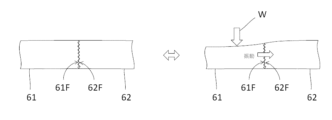
- FIG. 32 shows the state when the load W is applied to the cushion body 61, and the left side shows the state when the load W is not applied.
- the cushion bodies are accommodated so as to be compressed by the mattress cover 60 so that the gaps between the cushion bodies adjacent to each other in the left-right direction widen and the limbs do not fall down, the contact surfaces of the plurality of cushion bodies 61 and 62 are increased. Since the frictional force (engagement force) is further increased, there is a problem that the vibration when turning over is more likely to be transmitted.
- a mattress according to the present invention has a mattress cushion, and is a mattress on which a plurality of people can lie horizontally on the mattress cushion.
- Each of the plurality of cushion bodies includes a cushion body, each of the plurality of cushion bodies is formed of a filament three-dimensionally combined body composed of a plurality of filaments, and has a contact surface that contacts another adjacent cushion body, each of the plurality of cushion bodies end of the filament does not enter into another adjacent cushion body.
- each of the plurality of cushion bodies may be configured such that the ends of the filaments do not protrude beyond the contact surface over the entire area of the contact surface.
- each of the plurality of cushion bodies has a repulsive force of 100 N or more and 200 N or less, and a contact frictional force on the contact surface between the adjacent cushion bodies is more than 0 N and less than 50 N. good.
- the contact frictional force is less than 50N
- the use of the cushion body with the repulsive force of 100N or more and 200N or less significantly damps the amplitude of the vibration on the contact surface. Therefore, it is possible to further suppress transmission of vibrations caused by one user tossing and turning to the other user.
- the repulsive force in the present invention can be measured by the following method. First, a sample to be measured is placed on a horizontal table, and the thickness of the sample when not compressed is measured and defined as L1 (mm). Next, a rod-shaped pressure member (load element) having a circular plate with a diameter of 150 mm horizontally provided at the tip is brought into vertical contact with the central portion of the upper surface of the sample, and a load is applied to the sample to move the sample in the thickness direction. Compress.
- the contact friction force in the present invention can be measured by the following method.
- two adjacent cushion bodies are cut so as to form rectangular parallelepipeds with a square of 20 cm in horizontal plane, leaving contact surfaces.
- the two cut cushion bodies are sandwiched between two square plates each having a side of 20 cm in the thickness direction (vertical direction), and each cushion body is fixed by applying a pressure of 1000 Pa to the metal plate.
- a 2 cm gap is provided between one side of the metal plate and the contact surface of the cushion body so that the contact surface is not hidden by the metal plate.
- the two cushion bodies are brought into contact with each other at their contact surfaces, and pressure is applied to the two cushion bodies from both sides so that a pressure of 200 Pa is applied in a direction perpendicular to the contact surfaces.
- a force is applied from the center of the metal plate in a direction parallel to the contact surface so as to apply a shearing force in the thickness direction of each cushion, and each cushion is slid 5 cm in the thickness direction.
- N the maximum value of the force applied at that time be the contact friction force.
- each of the plurality of cushion bodies may have a smooth surface layer on the contact surface.
- the smooth surface layer is a layer from the surface of the cushion body to a depth of 2 mm, has a higher bulk density than the inside, and the cut end (cut end) of the filament protrudes outward from the surface. It is assumed that there is no layer.
- a mattress according to the present invention is a mattress comprising a mattress cushion comprising a plurality of cushion bodies and a mattress cover accommodating the mattress cushion, wherein the mattress cushion comprises a plurality of separable cushion bodies.
- At least one cushion body among the plurality of cushion bodies includes an electronic component having a communication function, and each of the plurality of cushion bodies is formed of a filament three-dimensionally combined body composed of a plurality of filaments, and adjacent to each other. The filament ends of each of the plurality of cushion bodies do not enter into other adjacent cushion bodies.
- each of the plurality of cushion bodies may be configured such that the ends of the filaments do not protrude beyond the contact surface over the entire area of the contact surface.
- a method for accepting an order for a mattress is a method for accepting an order for a mattress configured as described above, in which a plurality of cushion bodies are housed in a mattress cover, wherein each of the sections in which the plurality of cushion bodies are arranged is provided.
- a cushion information input receiving step of receiving an input of cushion information which is information about a cushion body, at a first communication terminal on the orderer side, and a cushion information input reception step of transmitting the received cushion information to a second communication terminal on the order receiver side.
- the cushion information includes at least information on the shape of the cushion body for each section. According to this method, even when ordering a mattress including a cushion body of a different shape, it is possible to prevent ordering errors such as the mattress cover not fitting.
- vibration is less likely to be transmitted between different cushion bodies. Further, according to the mattress order receiving method of the present invention, the convenience of ordering a mattress having the above effects is improved.
- FIG. 1 is a perspective view of a mattress according to a first embodiment
- FIG. 2 is an exploded perspective view of the mattress cover in FIG. 1
- FIG. Fig. 2 is an exploded perspective view of a mattress cushion that is housed within the mattress shown in Fig. 1
- It is a schematic block diagram of a cut surface smoothing apparatus. It is an external view of cut surface FL1 before being smoothed. It is an external view of cut surface FL1 after being smoothed.
- FIG. 4 is a conceptual diagram showing an example of a processing method for smoothing a cut surface of a cushion body; It is a conceptual diagram which shows a mode when using the mattress which concerns on 1st Embodiment.
- FIG. 4 is a conceptual diagram showing an example of a processing method for smoothing a cut surface of a cushion body
- FIG. 4 is a conceptual diagram showing how vibration is blocked when the mattress according to the first embodiment is used.
- FIG. 4 is a conceptual diagram showing an example of a processing method for smoothing a cut surface of a cushion body;
- FIG. 11 is a conceptual diagram showing a state when using the cushion body according to the second embodiment;
- FIG. 11 is a conceptual diagram showing how vibration is blocked when the cushion body according to the second embodiment is used; It is a perspective view of the mattress which concerns on 3rd Embodiment. It is a top view of the mattress which concerns on 3rd Embodiment.
- FIG. 11 is a perspective view of a mattress according to a modified example of the third embodiment;
- FIG. 11 is a perspective view showing the shape of a cushion body that can be used as an application example of the mattress according to the third embodiment; It is a conceptual diagram showing a specific application example of the mattress according to the third embodiment and viewed from the front (head direction).
- FIG. 18 is a conceptual diagram when a specific application example of the mattress shown in FIG. 17 is viewed from the right side (right direction).
- FIG. 4 is a conceptual diagram of a cushion body in which an electronic component having a communication function is housed; 1 is a block configuration diagram showing a configuration example of a mattress system; FIG. 1 is a block diagram of an order receiving system; FIG. It is a flow chart about a mattress provision process.
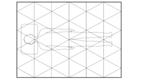
- FIG. 10 is an explanatory diagram of the layout of each section when the section is mainly shaped like a rhombus;
- FIG. 10 is an explanatory diagram regarding the arrangement of each section when the shape of the section is mainly an equilateral triangle;
- FIG. 10 is an explanatory diagram regarding the arrangement of each section when the shape of the section is mainly an equilateral triangle;
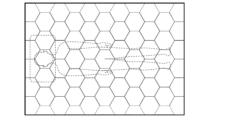
- FIG. 10 is an explanatory diagram regarding the arrangement of each section when the shape of the section is mainly a regular hexagon;
- FIG. 10 is an explanatory diagram regarding the layout of each section when the section is mainly shaped like a rhombus;
- FIG. 10 is an explanatory diagram regarding the arrangement of each section when the shape of the section is mainly an equilateral triangle;
- FIG. 10 is an explanatory diagram regarding the arrangement of each section when the shape of the section is mainly an equilateral triangle;
- FIG. 10 is an explanatory diagram regarding the arrangement of each section when the shape of the section is mainly
- FIG. 10 is an explanatory diagram regarding the arrangement of each section when the shape of the section is mainly a regular hexagon; It is a conceptual diagram which shows the use condition of the mattress which concerns on a prior art example. It is a conceptual diagram which shows the use condition of the mattress which concerns on a prior art example.
- FIG. 10 is a diagram for explaining transmission of vibration in a conventional mattress;
- FIG. 1 is a perspective view of a mattress 1 according to the first embodiment.
- the vertical, horizontal, and front-rear directions of the mattress 1 are as shown in FIG.
- the schematic positions of the respective cushion bodies 21 to 26 are indicated by dashed lines.
- the mattress 1 includes a mattress cover 10 covering its entire outer surface and a mattress cushion 20 housed therein. As a whole, the mattress 1 has the shape of a rectangular parallelepiped having sides in the front-rear direction (length direction), the left-right direction, and the up-down direction (thickness direction). The vertical dimension is sufficiently smaller than the horizontal dimension.
- the mattress cushion 20 is composed of cushion bodies 21 to 26 which are divided into two in the left-right direction and three in the longitudinal direction, and which are formed of a total of six filament three-dimensionally combined bodies.
- the mattress 1 according to the first embodiment is normally placed on a horizontal floor, bed, or the like, and used in a form in which two users lie side by side on the upper side of the mattress 1 .
- the up-down direction of the mattress 1 coincides with the vertical direction.
- the mattress 1 can be suitably used by setting the size in the front-back direction to substantially match the user's height direction, but the size in the front-back direction and the left-right direction can be freely changed according to preference.
- the mattress cover 10 has a top side cover 11, a bottom side cover 12 and a fastener 13.
- the upper surface side cover 11 and the bottom surface side cover 12 are connected by a fastener 13 in a state in which the mattress cushion 20 is put inside the upper surface side cover 11 and the bottom surface side cover 12.
- the fastener 13 has a structure that is difficult to stretch compared to other parts of the mattress cover 10, and plays a role of preventing the circumference of the mattress cover 10 from stretching (role as a stretch preventing member).
- the fastener 13 has a substantially constant vertical position (height) and is provided so as to encircle the outer peripheral surface of the mattress cover 10 when viewed from above.
- a fastener using a woven tape is used as an extension preventing member, and this fastener is arranged so as to extend over the entire connecting portion of the top side cover 11 and the bottom side cover 12 .
- opening the fastener 13 the top side cover 11 and the bottom side cover 12 can be completely separated.
- the stretch prevention member prevents the mattress cover 10 from stretching in the longitudinal direction and prevents the gaps between the cushion bodies 21 to 26 from widening due to the mattress cover 10 stretching.
- the extension prevention member is not limited to one that completely prevents the extension.
- the stretch-preventing member must be a member that stretches within 2 cm per 1 m, preferably within 1 cm per 1 m, when pulled with a force of 100 N.
- the elongation per meter is 0.5 cm or less when pulled with a force of 100 N.
- a material that can be used as the stretch-preventing member includes a woven tape made of chemical fibers.
- the height from the bottom surface portion 12a to the top surface portion 11a is within a range of 50 to 99% (the position closer to the top surface portion 11a than the center).
- the stretch-preventing member is preferably arranged so as to continuously surround the peripheral surface portion 10A of the mattress cover 10, including two longitudinally parallel sides (a left-facing side and a right-facing side).
- This embodiment adopts a strip-shaped stretch preventing member, but in addition to such a shape, for example, it is designed so that the entire peripheral surface 10A functions as a stretch preventing member using canvas fabric or the like. You may Further, in order to improve air permeability, it is desirable to provide a plurality of air vents and a mesh fabric having excellent air permeability in the peripheral surface portion 10A.
- the shape of the top surface portion 11a and the bottom surface portion 12a is not limited to a rectangle as in the present embodiment, and may be, for example, a rectangle with rounded corners.
- the boundary portions (vertically extending sides) between the front, rear, left, and right side surfaces of the peripheral surface portion 10A may also be similarly rounded.
- FIG. 2 is an exploded perspective view of the mattress cover 10 in FIG. More specifically, FIG. 2 is a schematic exploded perspective view when the mattress cover 10 is disassembled into a top side cover 11 and a bottom side cover 12. As shown in FIG. Each cover 11 , 12 can be connected by a fastener 13 . Fastener 13 functions as a stretch-preventing member as previously described.
- the upper surface side cover 11 in the state shown in FIG. 2(A) has a rectangular upper surface portion 11a that contacts the user while sleeping, and a peripheral surface portion 11b that is composed of four rectangular side surfaces connected to the upper surface portion 11a. When viewed as a whole, it has a substantially rectangular parallelepiped shape with a space inside. An upper fastener member 13a is provided on the peripheral surface portion 11b.
- the bottom surface side cover 12 in the state shown in FIG. 2(B) has a rectangular bottom surface portion 12a in contact with a horizontal floor, bed, etc., and a peripheral surface portion 12b composed of four rectangular side surfaces connected to the bottom surface portion 12a. When viewed as a whole, it has a substantially rectangular parallelepiped shape with a space inside.
- a lower fastener member 13b is provided on the peripheral surface portion 12b. When the upper fastener member 13a and the lower fastener member 13b are engaged, the fastener 13 in FIG. 1 is formed.
- FIG. 3 is an exploded perspective view of the mattress cushion 20 housed in the mattress 1 shown in FIG.
- the mattress cushion 20 can be divided into six cushion bodies 21 to 26 in the left-right direction and the length direction. From another point of view, the mattress cushion 20 has three cushion bodies 21 to 23 arranged in order in the length direction and three cushion bodies 24 to 26 arranged in order in the length direction. formed by
- the six cushion bodies 21 to 26 are formed of resin filament three-dimensionally combined.
- a filament three-dimensionally bonded body is an elastic member obtained by three-dimensionally fusion-bonding molten filaments of a thermoplastic resin.
- molten thermoplastic resin is extruded vertically downward from a plurality of horizontally arranged nozzles.
- a molten filament having a cross-sectional diameter of about 1 mm is dropped into cooling water, and a loop is formed by the buoyancy of the water.
- a three-dimensional combination of filaments is obtained.
- the filaments are formed at both ends in the thickness direction and width direction.
- a smooth surface layer having a density higher than that of the central portion in the thickness direction can be formed.
- the thickness (vertical dimension) of the three-dimensional filament assembly is preferably within the range of 10 to 25 cm.
- the filament diameter (cross-sectional diameter) is preferably in the range of 0.5 to 2 mm, and the bulk density is preferably in the range of 30 to 150 kg/m 3 .
- the filament diameter of the three-dimensionally bonded filament is less than 0.5 mm, the water will be drained after washing with water and the drying time will be long. Conversely, if the filament diameter exceeds 2 mm, the soft feel of the filament three-dimensional combination is likely to be lost. If the bulk density of the three-dimensionally bonded filament is less than 30 kg/m 3 , the three-dimensionally bonded filament itself tends to be deformed in the longitudinal direction, and elliptical grooves and depressions are likely to occur on the surface of the mattress. Conversely, if the bulk density exceeds 150 kg/m 3 , the three-dimensional filament assembly becomes heavy and difficult to transport.
- the bulk density of the three-dimensionally bonded filament can be measured, for example, by a measurement method using a rectangular parallelepiped measurement sample.
- this measurement method first, the mass W (kg) of the measurement sample and the size (m) of the measurement sample in each direction (vertical direction, horizontal direction, and height direction) are measured. Also, the volume V (m 3 ) of the measurement sample is calculated by multiplying the size (m) of the measurement sample in each direction (longitudinal direction, horizontal direction, height direction). The bulk density (kg/m 3 ) is calculated by dividing the mass W (kg) of the measurement sample by the volume V (m 3 ) of the measurement sample.
- the six cushion bodies 21 to 26 have contact surfaces between adjacent cushion bodies in the left-right direction, that is, contact surfaces 21f and 24f between the cushion bodies 21 and 24, and contact surfaces 21f and 24f between the cushion bodies 22 and 25.
- Smooth surface layers are formed on the surfaces 22f and 25f and the contact surfaces 23f and 26f between the cushion bodies 23 and 26, respectively.
- This smooth surface layer is a layer up to a depth of 2 mm from the surface of the cushion body, and has a higher bulk density than the inside, and the cut ends (cut ends) of the filaments do not protrude outward from the surface. be.
- Each of the contact surfaces 21f to 26f is a surface parallel to the vertical direction (thickness direction) and perpendicular to the horizontal direction.
- the smooth surface layer prevents the ends of the filaments of one cushion (the cut ends of the filaments and the loop protrusions of the filaments) from entering inside the filaments of the other cushion on the contact surfaces of the adjacent cushions. It is formed in order to prevent this, and a state in which the filaments are fused (bonded) to each other at a high density is preferable so that the loose filaments do not form protrusions.
- a method for forming the smooth surface layer for example, a method of manufacturing a three-dimensional filament assembly (network structure) using a shoot described in Patent Document 1 and simultaneously forming a smooth surface layer on the surface layer (hereinafter referred to as It may be referred to as the "first method"), or a method of forming a three-dimensionally bonded filament, cutting it into a predetermined size, and then pressing the cut surface while heating and melting it (hereinafter referred to as a method of forming the filament). may be referred to as a "second method").
- volume of air is preferably 30% or more and 85% or less. If the porosity is less than 30%, there is a concern that the air permeability will decrease and the repulsive force will become too high. On the other hand, if the porosity exceeds 85%, there is a concern that the number of filaments that are loose (existing alone) will increase and the frictional force with the adjacent cushion body will become too high.
- the degree of smoothness is sufficient as long as it prevents the ends of the filaments of one cushion from entering inside the filaments of the other cushion on the contact surface of the adjacent cushion.
- the smoothness may be obtained by applying pressure with a plate or roller while melting the surface layer of the three-dimensionally bonded filament so that the range is 30% or more and 85% or less.
- a smooth surface layer on the surface layer at the same time as manufacturing the three-dimensional filament assembly.
- a smooth surface layer can be formed by the second method on the cut surfaces produced by cutting the manufactured three-dimensionally bonded filament.
- the cut surface smoothing device Xa is a device that smoothes the cut surface FL1 of the three-dimensional filament assembly FL cut to a predetermined size in the previous step.
- the rollers R are provided on both the left and right sides of the conveyor C so as to face each other in the left and right direction, and are rotatably installed with their vertically extending central axis as the axis of rotation.
- the outer surface of one of the left and right rollers R contacts one cut surface FL1 of the three-dimensional filament assembly FL conveyed by the conveyor C, and the outer surface of the other roller R contacts the other cut surface FL1.
- the distance between the outer surfaces of the rollers R is set to be slightly smaller than the distance between the cut surfaces FL1 of the three-dimensional filament assembly FL.
- a heater H for heating the roller R is arranged inside each roller R.
- the heater H employs, for example, a halogen heater, and heats the roller R so that at least the temperature of the outer surface of the roller R is equal to or higher than the melting point of the three-dimensional filament assembly FL.
- the specific form of the heater H is not particularly limited within the scope of the present invention. For example, it may be one that outputs hot air or one that uses IH (Induction Heating). Further, the heater H may heat the roller R from outside.
- each roller R rotates in the direction indicated by the dashed arrow in FIG. 5 due to the force received from the cutting surface FL1. That is, each roller R rotates in the same direction as the conveying direction of the conveyor C (that is, so that the direction of movement at the contact points is the same) while hitting the cut surface FL1.
- a driving device such as a motor for rotating the roller R may be provided, and the driving device may rotate the roller R in accordance with the transport speed of the three-dimensional filament assembly FL.
- each cut surface FL1 is slightly pressed by the rollers R in the conveying direction. move on.
- the outer surface of each roller R is at a temperature higher than the melting point of the three-dimensional filament assembly FL, each cut surface FL1 is smoothed.
- the entire filament three-dimensional combined body FL finishes passing through the positions sandwiched between the rollers R, the entire cut surface FL1 is smoothed. In this way, it is possible to obtain a filament three-dimensional combination FL in which cut surfaces FL1 on both left and right sides are smoothed.
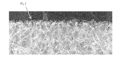
- FIG. 5 shows an example of an external view (photograph) of the cut surface FL1 before smoothing
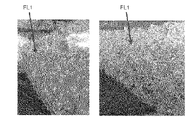
- FIG. 6 shows an example of an external view (photograph) of the cut surface FL1 after smoothing.
- FIG. 5 the figure seen from the direction substantially orthogonal to cut surface FL1 is shown.
- FIG. 6 left and right views are shown from slightly different directions.
- the cut surface FL1 before being smoothed has a conspicuous non-uniformity. , exposed ends of the filaments are seen here and there.
- the exposed filament ends and the like are melted and pressed by the roller R, and are fused to nearby filaments or deformed in the pressing direction. is smoothed compared to the cut surface FL1 shown in FIG. Further, the cut surface FL1 is flattened as a result of being pressed by the roller R while the entire filament is heated and melted. This achieves the formation of a smooth surface layer by the second method.
- a specific method for forming a smooth surface layer by the second method is not limited to the method using a roller as described above.
- the heated flat plate 30 may be pressed in a direction perpendicular to the cut surface to form a smooth surface on the cut surface.
- heating means for the flat plate 30 in addition to using a halogen heater, high-frequency induction heating (IH) that heats using electromagnetic induction, or ultrasonic waves that generate heat at the boundary surface by applying ultrasonic vibration to a thermoplastic resin.
- IH high-frequency induction heating
- ultrasonic waves that generate heat at the boundary surface by applying ultrasonic vibration to a thermoplastic resin.
- a plastic welder manufactured by Ultrasonic Industry Co., Ltd.
- the second method has been exemplified as a method for reducing the contact frictional force of the cut surface that becomes the contact surface, the method is not limited to this method as long as the method can reduce the contact frictional force of the cut surface.
- a high-speed cutting machine such as a circular saw can be used as a cutting device for cutting the three-dimensionally bonded filament with a knife.
- the filament 3D conjugate has a high porosity (80-95%) and is flexible with a diameter of each filament of about 1 mm.
- a filament cut in a deformed state tries to return to its pre-deformed state when the compressive force and impact force of the rotating teeth are removed, but the distance that each filament returns differs, so the cut surface becomes uneven.
- the cutting surface has irregularities of about 5 to 10 mm. If the unevenness exceeds 5 mm, the cut ends of some of the filaments on the cut surface of the three-dimensional filament bond enter into the adjacent three-dimensional bond of filaments, generating an engaging force and increasing the contact friction force. Become.
- the three-dimensionally bonded filament is cut with a circular saw while being cooled to a temperature at which its elasticity becomes small. and cutting with a circular saw in a state in which the three-dimensional filament assembly is compressed in the thickness direction (a state in which the filaments are difficult to move during cutting).
- the compressive force applied from the rotating teeth to the three-dimensionally bonded filament body is reduced to reduce the amount of deformation of the three-dimensionally bonded filament body for cutting. be.
- the force applied from the tooth tip to the filament three-dimensional bonded body is preferably 100 N or less, and the pressure applied from the rotating tooth to the filament three-dimensional bonded body. is preferably 5,000,000 pascals or less.
- the smoothness index of the cut surface is preferably 0 mm or more and 3 mm or less, more preferably 0 mm or more and 1 mm or less.
- the smoothness index of the cut surface of the cushion body can be measured by the following method. First, a state in which the cushion body is sandwiched and fixed in the thickness direction (direction parallel to the cut surface) using two metal plates ⁇ having a plurality of 5 mm long metal needles fixed on the surface at intervals of 5 cm ( The state in which the metal needle of each metal plate ⁇ is stuck in the cushion body). In this state, a metal plate ⁇ having a pressing surface having the same shape and area as the cut surface is arranged so that the pressing surface faces the cut surface, and this metal plate ⁇ is directed toward the cut surface. Move parallel.
- the metal plate from the time when the cut surface is pressed against the cut surface so that a pressure of 100 Pa is applied in the vertical direction to the time when the cut surface is pressed so that the pressure of 500 Pa is applied in the same direction.
- the moving distance of ⁇ is measured, and this measured moving distance is taken as the smoothness index.
- the smaller the number of filaments protruding outward on the cut surface and the shorter the length of the filament the lower the smoothness index of the cut surface, and it can be said that the cut surface has a high degree of smoothness.
- a cover may be provided to cover the cut surface in order to reduce the contact friction force of the cut surface. Reducing the contact friction force of the cut surface facilitates insertion and removal of the mattress cover.
- FIG. 8 is a conceptual diagram showing how the mattress 1 according to the first embodiment is used.
- FIG. 9 is a conceptual diagram showing how vibration is blocked when the mattress 1 according to the first embodiment is used.
- the cushion body 21 and the cushion body 24 are adjacent to each other, and the right side shows the state when the load W is applied to the cushion body 21, and the left side shows the state when the load W is not applied. .
- the mattress 1 has the mattress cushion 20, and a plurality of persons can lie on the mattress cushion 20 in the horizontal direction, and the mattress cushion 20 can be separated in the horizontal direction.
- a plurality of cushion bodies 21-26 In the mattress 1, each of the plurality of cushion bodies 21-26 is formed of a filament three-dimensional combination of a plurality of filaments, and has contact surfaces 21f-26f that come into contact with other adjacent cushion bodies. Furthermore, in the mattress 1, the ends of the filaments of each of the plurality of cushion bodies 21 to 26 (the cut ends of the filaments and the loop protrusions of the filaments) are placed in the other adjacent cushion bodies (that is, the other adjacent cushions inside the contact surface of the body).
- each of the plurality of cushion bodies 21 to 26 prevents filament ends from protruding outside the contact surfaces 21f to 26f in all areas of the contact surfaces 21f to 26f. Therefore, the ends of the filaments are reliably prevented from getting into other adjacent cushion bodies.
- each of the plurality of cushion bodies 21 to 26 has a repulsive force of 100 N or more and 200 N or less, and a contact frictional force on the contact surfaces 21f to 26f between the adjacent cushion bodies is more than 0 N and less than 50 N.
- the contact frictional force is less than 50N, the use of the cushion body with the repulsive force of 100N or more and 200N or less significantly damps the amplitude of the vibration on the contact surface. Therefore, it is possible to further suppress transmission of vibrations caused by one user tossing and turning to the other user.
- each of the plurality of cushion bodies 21-26 has a smooth surface layer on the contact surfaces 21f-26f. Therefore, since there is no filament cut end (cut end) on the contact surfaces 21f to 26f, not only the static contact friction force but also the dynamic contact friction force can be reduced. Even if there is, vibration is less likely to be transmitted to the contact surfaces 21f to 26f.
- the second embodiment is basically the same as the first embodiment except that the contact surfaces 21f to 26f of the cushion bodies 21 to 26 are formed with recesses, which will be described later.
- a cushion body 121 corresponds to the cushion body 21 of the first embodiment
- a cushion body 124 corresponds to the cushion body 24 of the first embodiment.
- FIG. 10 shows one example of a method of forming a smooth surface layer by the second method, which is adopted in the second embodiment.
- FIG. 10 shows how two cushion bodies 121 and 124 are processed, but the remaining four cushion bodies (cushion bodies corresponding to the cushion bodies 22, 23, 25 and 26 of the first embodiment) are shown. Similar processing is performed for
- the cut surfaces (contact surfaces 121f, 123f) of the cushion bodies 121, 124 are pressed by a heated roller 130.
- the cut surface is flattened and densified as a result of being pressed by the roller 130 in a state in which the entire filament is heated and melted, thereby forming a smooth surface layer.
- a crown is formed on the roller surface that contacts the cut surface. That is, the diameter dimension of the roller 130 with respect to the rotation axis increases toward the inner side from both ends in the rotation axis direction.
- the method of heating the roller 130 may be the same as the method of heating the flat plate 30 described above, for example.
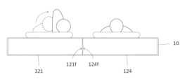
- FIG. 11 is a conceptual diagram showing how the cushion bodies 121 and 124 according to the second embodiment are used
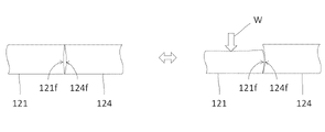
- FIG. FIG. 10 is a conceptual diagram showing how it is done.
- the cushion body 121 and the cushion body 124 are adjacent to each other, and the right side shows the state where the load W is applied to the cushion body 121, and the left side shows the state when the load W is not applied.
- the cushion body 121 As the user on the left side of FIG. 11 rolls over, the cushion body 121 is vertically moved (vibrated). Since the force (engagement force) is almost eliminated, transmission of vertical motion (vibration) to the cushion body 124 is suppressed as much as possible. As a result, an effect is obtained in which the vibration is less likely to be transmitted to the user on the right side. Similarly, the vibration caused by the user on the right side rolling over is less likely to be transmitted to the user on the left side.
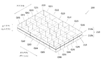
- FIG. 13 is a perspective view of a mattress 200 according to a third embodiment.
- FIG. 14 is a plan view of the mattress 200.
- the vertical, horizontal, and longitudinal directions of the mattress 200 are as shown in FIG. 13 and 14, to facilitate understanding of the internal configuration of the mattress 200, schematic positions of the respective cushion bodies Q11 to Q66 are indicated by dashed lines.
- the mattress 200 includes a mattress cover 210 that covers the entire outer surface thereof, and a mattress cushion 220 that is housed therein and formed of a three-dimensional filament combination. As a whole, the mattress 200 has a rectangular parallelepiped shape having sides in the front-rear direction (length direction), the left-right direction, and the up-down direction (thickness direction). The vertical dimension is sufficiently smaller than the horizontal dimension.
- the mattress cushion 220 is composed of a total of 36 cushion bodies Q11 to Q66 divided into 6 in the left-right direction and 6 in the length direction.
- the mattress cushion 220 has a size that allows a plurality of people to lie side by side, but it can also be used by a single person.
- Each of the 36 cushion bodies Q11 to Q66 has a rectangular parallelepiped shape, and a smooth surface layer is formed on all outer surfaces of each of the cushion bodies Q11 to Q66.
- a smooth surface layer may be formed only on the contact surface with the adjacent cushion bodies.
- the mattress cover 210 has a top side cover 210a, a bottom side cover 210b and fasteners 213.
- the upper surface side cover 210a and the bottom surface side cover 210b are joined by a fastener 213 in a state in which the mattress cushion 220 is put inside the upper surface side cover 210a and the bottom surface side cover 210b.
- the fastener 213 has a structure that is difficult to stretch compared to other parts of the mattress cover 210, and plays a role of preventing the circumference of the mattress cover 210 from stretching (role as a stretching prevention member).
- the fastener 213 has a substantially constant vertical position (height) and is provided so as to make one turn around the outer circumferential surface of the mattress cover 210 when viewed from above.
- rectangular parallelepiped cushion bodies Q11 to Q66 having the same shape are accommodated in the mattress cover 210.
- two or more types of cushion bodies having at least one different repulsive force and shape are used. can be used. As a result, it is possible to easily change the cushion body of the mattress according to the position of the bed, the environment in which it is used, the physical condition of the user, and the functions that the user wants to use, thereby providing a comfortable sleeping environment under various changing conditions. can. Details of such an application will be described later.
- FIG. 15 is a perspective view of a mattress 290 according to a modified example of the third embodiment.
- Mattress 290 has a structure in which overlay mattress 270 is placed on top of mattress 200 shown in FIG.
- the overlay mattress 270 includes a mattress cover 210C that covers the entire outer surface thereof, and a mattress cushion 280 that is housed therein and formed of a single filament three-dimensional combination.
- the thickness of the mattress cushion 280 is preferably 10 mm or more and 50 mm or less. If the thickness is less than 10 mm, it is difficult to obtain the effect of preventing depression, and if it exceeds 50 mm, it is difficult to obtain the effect of dividing each cushion of the mattress 200 .
- FIG. 16 is a perspective view showing the shape of a cushion body that can be used as an application example of the mattress 200 according to the third embodiment.
- Various cushion bodies shown in FIG. 16 can be arbitrarily selected and used as the cushion bodies Q11 to Q66 in the mattress 200.
- FIG. 16 is a perspective view showing the shape of a cushion body that can be used as an application example of the mattress 200 according to the third embodiment.
- Various cushion bodies shown in FIG. 16 can be arbitrarily selected and used as the cushion bodies Q11 to Q66 in the mattress 200.
- FIG. 16(a) shows a rectangular parallelepiped cushion body Da.
- FIG. 16(b) shows a rectangular parallelepiped cushion body Db having a two-layer structure.
- the cushion body Db has a configuration in which an upper cushion body Dba with high resilience and a lower cushion body Dbb with ultra-high resilience are arranged vertically, so that body pressure dispersibility is not impaired and the body sinks even when sitting on the mattress. It can be used as a cushion body for sitting on the edge with very high repulsive force.
- FIG. 16(c) shows a rectangular parallelepiped cushion body Dc with one end raised in the front-rear direction. Even if the bed is not provided with a headboard, by arranging the cushion body Dc at the front end portion of the mattress cushion 220 in the front-rear direction, it is possible to obtain the effect of preventing the pillow from slipping down.
- FIG. 16(d) shows a rectangular parallelepiped cushion body Dd with one end raised in the left-right direction. Even if there is no handrail or wall on the side of the bed, the effect of preventing the comforter from slipping down can be obtained by arranging the cushion bodies Dd at the left and right ends of the mattress cushion 220 .
- FIG. 16(e) shows a rectangular parallelepiped cushion body De (a modified example of the cushion body Dd) in which one end in the left-right direction is raised.
- the cushion body De has an inclination angle of 90 degrees between the raised portion and the other portion, and at the same time, the corners of the raised portion are rounded. Therefore, the use of the cushion body De not only has the effect of preventing the comforter from slipping down, but also makes it possible to easily pull up the comforter that has slipped down.
- FIG. 16(f) shows a rectangular parallelepiped cushion body Df in which one end in the front-rear direction and the left-right direction is raised.
- the cushion body Df By installing the cushion body Df at the corner of the mattress head side (the front end portion of the mattress cushion 220), it can be used as a place for storing small items such as smartphones, medicines, or watches that are necessary for sleeping.
- the cushion body Df may be formed with a recess (holder) for storing a smartphone or a PET bottle on the upper surface of the cushion body so that the smartphone or drink in a PET bottle will not fall or fall over. good.
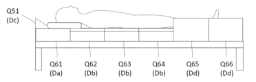
- FIG. 17 shows a specific application example of the mattress 200 according to the third embodiment, and is a conceptual diagram when viewed from the front (head direction).
- FIG. 18 shows a specific application example of the mattress 200 shown in FIG. It is a conceptual diagram when seen from (right direction). 17 and 18, the overlay mattress 270 is omitted and the mattress cover 210 conforming to the shape of the mattress cushion 220 is used.
- the four cushion bodies Q21, Q31, Q41, and Q51 shown in FIG. 16 (c)), and the three cushion bodies Q62 to Q64 and the three cushion bodies Q12 to Q14 are replaced by the rectangular parallelepiped cushion body Da to the two-layered rectangular parallelepiped cushion body Db (Fig. 16 ( b)), and the two cushion bodies Q65 and Q66 and the two cushion bodies Q15 and Q16 are replaced with a rectangular parallelepiped cushion body Dd (Fig. 16 ( d)).
- FIG. 19 shows a filament three-dimensional combination housing an electronic component having a communication function (hereinafter sometimes referred to as an IoT module) that can be used as another application example of the mattress 200 according to the third embodiment.
- FIG. 4 is a conceptual diagram of a formed cushion body; Various cushion bodies shown in FIG. 19 can be arbitrarily selected and used as the cushion bodies Q11 to Q66 in the mattress 200.
- FIG. The cushion body shown in FIG. 19 may be appropriately combined with the configuration of the cushion body shown in FIG. 16 described above.
- the IoT module housed in the cushion body includes a communication device, an electronic device connected to the communication device, and an internal battery.
- the IoT module may also be provided with electrical wiring for supplying power from the outside as needed.
- Examples of communication devices included in IoT modules include short-range wireless communication devices such as Wi-fi, Bluetooth, and NFC.
- a short-range wireless communication device is connected to a host communication device such as a smart phone (hereinafter sometimes simply referred to as a host device) to transmit and receive necessary data.
- FIG. 20 shows a configuration example of a mattress system composed of an IoT module and a host device 300. As shown in FIG.
- Information gathering devices such as temperature and humidity sensors, acceleration sensors, touch sensors, switches, and microphones are used as electronic devices included in the IoT module.
- the IoT module 301 having such an information collection device transmits collected information to the host device 300 as shown in FIG.
- the electronic devices included in the IoT module include, for example, LED lighting, fans, speakers, heaters, humidifiers, thermal insulation shutters, sterilization ion generators, aroma generators, massage vibrators, and airbags for body pillows. , calf-lifting airbags, pressure ulcer patient airbags, pressure ulcer prevention repositioning airbags, or up-and-down motion airbags for wake-up are employed.
- the IoT module 302 having such a function providing device receives data from the host device 300 through the communication device, and drives the function providing device based on the received data. That is, the function-providing device can also be said to be a drive device that is driven based on the data received by the communication device.
- an air mattress for pressure ulcer patients consisting of a plurality of airbags (sometimes called air cells) whose pressure can be individually controlled has been conventionally used.
- the cause of the occurrence and aggravation of pressure ulcers is poor blood circulation caused by long-term pressure on specific protruding parts such as bones of pressure ulcer patients who cannot turn over.
- By varying the pressure of each individual airbag at intervals high pressure is prevented from being applied to a specific area for a long period of time.
- the interior of one cushion body may contain a plurality of electronic devices, or may contain both the IoT module 301 having the information collecting device and the IoT 302 having the function providing device.
- external IoT modules 303 such as an indoor air conditioner and indoor lighting are provided outside the mattress 200 , and the external IoT modules 303 are controlled by the host device 300 .
- FIG. 19(a) shows a rectangular parallelepiped cushion body Ua equipped with a temperature and humidity sensor Ma (IoT module 301) having a communication function inside.
- the temperature/humidity sensor Ma measures the temperature/humidity inside the mattress and transmits data to the host device 300 such as a smartphone.
- the host device 300 can control the external IoT module 303 by sending data to the external IoT module 303 such as an indoor air conditioner according to a preset procedure.
- FIG. 19(b) shows a rectangular parallelepiped cushion body Ub provided with a touch sensor Mb (IoT module 301) having a communication function inside.
- the touch sensor Mb can transmit data (user's expression of intention) to the host device 300 simply by being touched by the user even in a dark bedroom.
- the host device 300 that has received the data sends the data to the IoT module 302 having the function of providing the function of a fan and the external IoT module 303 such as an indoor light according to a preset procedure. can be activated.
- FIG. 19(c) shows a rectangular parallelepiped cushion body Uc provided with a blower fan Mc (IoT module 302) having a communication function inside.
- the rotation speed of the blower fan Mc is controlled according to data sent from the host device 300 .
- FIG. 19(d) shows a cuboid-shaped cushion body Ud with an acceleration sensor Md (IoT module 301) having a communication function inside, with one end raised in the front-rear direction.
- an acceleration sensor Md IoT module 301
- data user's expression of intention
- the host device 300 that has received this data sends the data to an IoT module 302 that has a function providing function such as a blower fan and an external IoT module 303 such as an interior lighting lamp, in accordance with a preset procedure. can be activated.
- FIG. 19(e) shows a rectangular parallelepiped cushion body Ue having a microphone Me1 (IoT module 301) having a communication function and an LED lighting device Me2 (IoT module 302) having a communication function, and having one end raised in the front-rear direction. represents.
- the cushion body Ue the user can transmit data (the user's expression of intention) to the host device 300 simply by speaking into the microphone Me1 even in a pitch-black bedroom.
- the host device 300 that has received the data can operate the LED lighting device Me2 or the like according to a preset procedure.
- the host device 300 is a device having a telephone function such as a smart phone, when the user speaks into the microphone Me1, it is possible to answer the call (converse on the phone) with this voice. Also good.
- FIG. 19(f) shows a rectangular parallelepiped cushion body Uf provided with a plurality of cylindrical airbags Mf (IoT modules 302) having communication functions inside. If the cushion body Uf is used, by changing the internal pressure of the cylindrical airbag Mf, the repulsive force (ease of deformation) of the cushion body Uf can be changed without changing the height of the upper surface of the cushion body.
- the plurality of cylindrical airbags Mf are attached with an air pump Mfa capable of sending air into the airbags Mf and exhausting the air inside the airbags Mf. can change the internal pressure of the airbag Mf.
- FIG. 19(g) shows a rectangular parallelepiped two-layer cushion body Ug having an airbag Mg (IoT module 302) having a communication function at the bottom of the cushion body.
- the airbag Mg is provided with an air pump Mga capable of sending air into the airbag Mg and exhausting the air inside the airbag Mg. height can be changed.
- the right side shows a state in which air is sent into the inside of the airbag Mg
- the left side shows a state in which no air is sent.
- a mattress using a cushion body illustrated in FIG. 19 is a mattress including a mattress cushion made up of a plurality of cushion bodies and a mattress cover that accommodates the mattress cushion.
- the mattress cushion includes a plurality of separable cushion bodies, and at least one cushion body among the plurality of cushion bodies includes an electronic component having a communication function.
- each of the plurality of cushion bodies is formed of a filament three-dimensionally combined body composed of a plurality of filaments, and has a contact surface that contacts another adjacent cushion body. have.
- the ends of the filaments of each of the plurality of cushion bodies are in the other adjacent cushion bodies (that is, the contact of the other adjacent cushion bodies). inner than the surface) does not enter.
- each of the plurality of cushion bodies prevents the ends of the filaments from protruding outside the contact surface over the entire area of the contact surface. Therefore, the ends of the filaments are reliably prevented from getting into other adjacent cushion bodies.
- FIG. 21 is a block configuration diagram showing a configuration example of an order reception system.
- the order receiving system 40 shown in FIG. 21 includes a mobile terminal 41 as an example of an orderer's communication terminal, and a server 42 as an example of an orderer's communication terminal.
- the mobile terminal 41 is a smartphone in FIG. 21 as an example, it may be a tablet, a mobile phone, or the like.
- the communication terminal on the orderer side is not limited to a mobile terminal, and may be a PC (personal computer) or the like.
- the mobile terminal 41 has a touch panel operation section 41A, a communication module section 41B, a control section 41C, and a storage section 41D.
- the touch panel operation unit 41A is included in the liquid crystal display unit, and can operate the mobile terminal 41 by being touched.
- the communication module unit 41B performs, for example, 4G communication (WiMAX2, LTE-Advanced, etc.).
- the control unit 41C is, for example, a CPU, and controls the mobile terminal 41 as a whole.
- the storage unit 41D includes a ROM in which programs are stored, a RAM in which data is stored, and the like.
- the server 42 has an Ethernet section 42A, a control section 42B, and a storage section 42C.
- the Ethernet unit 42A is an Ethernet interface provided for IP communication with other devices (mobile terminal 41, etc.).
- the control unit 42B is, for example, a CPU, and controls the server 42 as a whole.
- the storage unit 42C includes, for example, an HDD (hard disk drive), RAM, and the like.
- the cushion information input reception step (step S1) is executed.
- the orderer operates the touch panel operation section 41A to input the cushion information.
- the orderer performs an input operation according to the web screen displayed on the display unit of the portable terminal 41 based on the data transmitted from the Ethernet unit 42A of the server 42 and received by the communication module unit 41B.
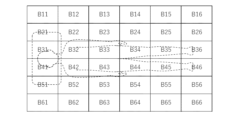
- FIG. 23 shows an example of section position numbers (numbers assigned to different section positions) used when ordering the mattress 200.
- section here means a section (block) in which one cushion body is arranged when viewed from above.
- the outer edge of the rectangle in FIG. 23 corresponds to the outer edge of the mattress 200 when viewed from above, and each position inside the rectangle corresponds to each position when the mattress 200 is viewed from above.
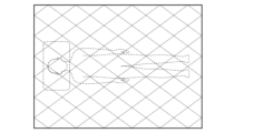
- FIG. 23 (as well as FIGS. 25-29, which will be described later), the schematic positions of the user and the pillow when lying alone on the mattress are indicated by dashed lines.
- the mattress cushion 220 is divided into 6 sections in the longitudinal direction and 6 sections in the left-right direction, and a total of 36 sections are set.
- the cushion body corresponding to the section position number Bx (x is a number) shown in FIG. 23 corresponds to the cushion body Qx in the examples shown in FIGS.
- the cushion body corresponding to section position number B11 shown in FIG. 23 corresponds to cushion body Q11 in the examples shown in FIGS.
- FIG. 24 shows an example of a mattress order form used when ordering the mattress 200.
- FIG. 24 when placing an order, it is possible to specify the level of the repulsive force of the cushion body, the shape of the cushion body, the presence or absence of an IoT module to be provided in the cushion body, and the type of the cushion body for each cushion body with different sections. It has become.
- the cushion body corresponding to the section position number B11 has a “high” repulsive force, a “rectangular parallelepiped” shape, and an “none” IoT module (that is, the IoT module is not installed). is specified).
- the cushion information input receiving step receives the input of the cushion information, which is information about the cushion bodies for each of the sections in which the plurality of cushion bodies Q11 to Q66 are arranged, at the communication terminal (portable terminal 41) of the orderer. is being processed.
- the cushion information also includes repulsive force information, shape information, and information on electronic components having a communication function (information on presence/absence and type of IoT module) of the cushion body for each section.
- the input-operated cushion information is stored in the storage unit 41D, and the input of the cushion information is accepted.
- step S2 the cushion information transmission step (step S2) is executed.
- the cushion information stored in the storage section 41D is transmitted to the server 42 by the communication module section 41B.
- step S3 the cushion information receiving step (step S3) is executed.
- the cushion information transmitted from the communication module section 41B is received by the Ethernet section 42A.
- the received cushion information is stored in the storage unit 42C.
- the mattress cover model number determination step (step S4) is executed.
- the control section 42B automatically determines the optimal mattress cover model number based on the cushion information stored in the storage section 42C. More specifically, a unique model number is assigned in advance to each of a plurality of types of mattress covers having different shapes and the like. Then, considering the shape of each cushion body, the function of the IoT module, the position of each cushion body, etc., determined from the cushion information, the optimal mattress cover is selected from among the multiple types of mattress covers. The selected mattress cover model number is determined as the optimal mattress cover model number.
- the shape and dimensions of the mattress cushion 220 are determined in consideration of the shape of the cushion body to be adopted, the presence or absence of an airbag function by the IoT module, etc. Consideration is given to whether the mattress cover conforms to Also, for example, the presence or absence of functions such as a microphone, LED lighting, and blower fan by the IoT module is considered, and whether or not the mattress cover can effectively work the functions is considered.
- step S5 the mattress information output step (step S5) is executed.
- the server 42 outputs information (mattress information) including the cushion information and the determined model number of the mattress cover.
- the mattress information is output, for example, by being transmitted from the Ethernet section 42A to an external manufacturing device.
- the manufacturing device can manufacture the mattress based on the received mattress information.
- the mattress information may be output by displaying the mattress information on a display unit (not shown) included in the server 42, for example.
- the worker can manufacture the mattress according to the displayed mattress information.
- the manufactured mattress is provided to the orderer, so that the orderer can use the ordered mattress.
- the sections in which the respective cushion bodies are arranged have a rectangular shape, but the shape of the sections is not particularly limited.
- the sections in which the respective cushion bodies are arranged may be rhombic, triangular, hexagonal, or the like.
- As the cushion body arranged in each section a columnar shape having a bottom surface substantially congruent with the section is adopted.
- FIG. 25 illustrates an arrangement form of each compartment when the shape of the compartment is mainly a rhombus
- FIGS. 26 and 27 illustrate an arrangement form of each compartment when the shape of the compartment is mainly an equilateral triangle
- FIG. 28 and FIG. 29 exemplify the arrangement form of each section when the shape of the section is mainly a regular hexagon.
- the present invention can be used for mattresses for various uses.
Landscapes
- Engineering & Computer Science (AREA)
- Health & Medical Sciences (AREA)
- Manufacturing & Machinery (AREA)
- Mechanical Engineering (AREA)
- Nursing (AREA)
- Life Sciences & Earth Sciences (AREA)
- Animal Behavior & Ethology (AREA)
- General Health & Medical Sciences (AREA)
- Public Health (AREA)
- Veterinary Medicine (AREA)
- Mattresses And Other Support Structures For Chairs And Beds (AREA)
Priority Applications (5)
| Application Number | Priority Date | Filing Date | Title |
|---|---|---|---|
| EP22849175.9A EP4378359A4 (en) | 2021-07-29 | 2022-07-05 | MATTRESS AND MATTRESS ORDERING METHOD |
| US18/290,804 US20240374047A1 (en) | 2021-07-29 | 2022-07-05 | Mattress and method for receiving order for mattress |
| JP2023538374A JP7656705B2 (ja) | 2021-07-29 | 2022-07-05 | マットレス、およびマットレスの注文受付方法 |
| CN202280051153.1A CN117677319A (zh) | 2021-07-29 | 2022-07-05 | 床垫、及床垫的订单受理方法 |
| JP2025048183A JP7811675B2 (ja) | 2021-07-29 | 2025-03-24 | マットレス、およびマットレスの注文受付方法 |
Applications Claiming Priority (2)
| Application Number | Priority Date | Filing Date | Title |
|---|---|---|---|
| JP2021-124490 | 2021-07-29 | ||
| JP2021124490 | 2021-07-29 |
Publications (1)
| Publication Number | Publication Date |
|---|---|
| WO2023008110A1 true WO2023008110A1 (ja) | 2023-02-02 |
Family
ID=85086736
Family Applications (1)
| Application Number | Title | Priority Date | Filing Date |
|---|---|---|---|
| PCT/JP2022/026686 Ceased WO2023008110A1 (ja) | 2021-07-29 | 2022-07-05 | マットレス、およびマットレスの注文受付方法 |
Country Status (5)
| Country | Link |
|---|---|
| US (1) | US20240374047A1 (https=) |
| EP (1) | EP4378359A4 (https=) |
| JP (2) | JP7656705B2 (https=) |
| CN (1) | CN117677319A (https=) |
| WO (1) | WO2023008110A1 (https=) |
Cited By (1)
| Publication number | Priority date | Publication date | Assignee | Title |
|---|---|---|---|---|
| US12285111B1 (en) | 2023-12-15 | 2025-04-29 | SENIAH Innovations Group, LLC | Modular mattress system and method |
Citations (9)
| Publication number | Priority date | Publication date | Assignee | Title |
|---|---|---|---|---|
| JPH07238460A (ja) * | 1994-02-28 | 1995-09-12 | Toyobo Co Ltd | 積層弾性構造体と製法及びそれを用いた製品 |
| JPH07324272A (ja) * | 1994-05-25 | 1995-12-12 | Toyobo Co Ltd | 難燃性補強網状体と製法及びそれを用いた製品 |
| JP2008067979A (ja) * | 2006-09-15 | 2008-03-27 | Showa Denko Kk | 生体情報計測用パネル |
| US20080098533A1 (en) * | 2006-10-25 | 2008-05-01 | Erdman Thomas C | Modular mattress system |
| JP4966438B2 (ja) | 2010-09-15 | 2012-07-04 | 株式会社ウィーヴァジャパン | 網状構造体製造装置および網状構造体製造方法 |
| JP3196514U (ja) * | 2014-11-11 | 2015-03-19 | 山越株式会社 | 介護用布団および介護用敷布団セット |
| WO2018150815A1 (ja) | 2017-02-15 | 2018-08-23 | 株式会社エアウィーヴ | マットレス |
| JP2018130216A (ja) * | 2017-02-14 | 2018-08-23 | 株式会社エアウィーヴ | マットレス |
| JP2019025193A (ja) * | 2017-08-02 | 2019-02-21 | 株式会社エアウィーヴ | 情報処理方法、マットレスの製造方法、情報処理システム、およびプログラム |
Family Cites Families (6)
| Publication number | Priority date | Publication date | Assignee | Title |
|---|---|---|---|---|
| US20040254856A1 (en) * | 2003-06-16 | 2004-12-16 | Dotson Robert Cameron | Custom designed floormat order placement system |
| US7454810B2 (en) * | 2006-06-20 | 2008-11-25 | Wells Thomas J | Divided support mattress |
| CN103315560B (zh) * | 2013-06-25 | 2016-02-24 | 泰已科新材料(苏州)有限公司 | 一种床垫 |
| US20150296993A1 (en) * | 2014-04-22 | 2015-10-22 | Dennis M. Boyd | Mattress assembly |
| JP3208227U (ja) * | 2016-10-19 | 2016-12-28 | 株式会社ウィードメディカル | マットレス |
| CN211092933U (zh) * | 2019-06-19 | 2020-07-28 | 耀亿工业股份有限公司 | 透气床架与透气床组 |
-
2022
- 2022-07-05 JP JP2023538374A patent/JP7656705B2/ja active Active
- 2022-07-05 EP EP22849175.9A patent/EP4378359A4/en active Pending
- 2022-07-05 WO PCT/JP2022/026686 patent/WO2023008110A1/ja not_active Ceased
- 2022-07-05 CN CN202280051153.1A patent/CN117677319A/zh active Pending
- 2022-07-05 US US18/290,804 patent/US20240374047A1/en active Pending
-
2025
- 2025-03-24 JP JP2025048183A patent/JP7811675B2/ja active Active
Patent Citations (9)
| Publication number | Priority date | Publication date | Assignee | Title |
|---|---|---|---|---|
| JPH07238460A (ja) * | 1994-02-28 | 1995-09-12 | Toyobo Co Ltd | 積層弾性構造体と製法及びそれを用いた製品 |
| JPH07324272A (ja) * | 1994-05-25 | 1995-12-12 | Toyobo Co Ltd | 難燃性補強網状体と製法及びそれを用いた製品 |
| JP2008067979A (ja) * | 2006-09-15 | 2008-03-27 | Showa Denko Kk | 生体情報計測用パネル |
| US20080098533A1 (en) * | 2006-10-25 | 2008-05-01 | Erdman Thomas C | Modular mattress system |
| JP4966438B2 (ja) | 2010-09-15 | 2012-07-04 | 株式会社ウィーヴァジャパン | 網状構造体製造装置および網状構造体製造方法 |
| JP3196514U (ja) * | 2014-11-11 | 2015-03-19 | 山越株式会社 | 介護用布団および介護用敷布団セット |
| JP2018130216A (ja) * | 2017-02-14 | 2018-08-23 | 株式会社エアウィーヴ | マットレス |
| WO2018150815A1 (ja) | 2017-02-15 | 2018-08-23 | 株式会社エアウィーヴ | マットレス |
| JP2019025193A (ja) * | 2017-08-02 | 2019-02-21 | 株式会社エアウィーヴ | 情報処理方法、マットレスの製造方法、情報処理システム、およびプログラム |
Non-Patent Citations (1)
| Title |
|---|
| See also references of EP4378359A4 |
Cited By (1)
| Publication number | Priority date | Publication date | Assignee | Title |
|---|---|---|---|---|
| US12285111B1 (en) | 2023-12-15 | 2025-04-29 | SENIAH Innovations Group, LLC | Modular mattress system and method |
Also Published As
| Publication number | Publication date |
|---|---|
| JP7656705B2 (ja) | 2025-04-03 |
| JP7811675B2 (ja) | 2026-02-05 |
| EP4378359A4 (en) | 2024-11-06 |
| CN117677319A (zh) | 2024-03-08 |
| US20240374047A1 (en) | 2024-11-14 |
| JP2025094173A (ja) | 2025-06-24 |
| JPWO2023008110A1 (https=) | 2023-02-02 |
| EP4378359A1 (en) | 2024-06-05 |
Similar Documents
| Publication | Publication Date | Title |
|---|---|---|
| US10864137B2 (en) | System and method of an adjustable bed with a vibration motor | |
| US10064784B2 (en) | System and method of an adjustable bed with a vibration motor | |
| US9182750B2 (en) | System and method of a bed with a safety stop | |
| EP3285618B1 (en) | Support cushions with active ventilation | |
| EP3106066B1 (en) | Body support with fluid system and method of operating same | |
| JP7811675B2 (ja) | マットレス、およびマットレスの注文受付方法 | |
| US6372076B1 (en) | Convoluted multi-layer pad and process | |
| KR20190052047A (ko) | 모니터링 시스템 | |
| WO2013173640A1 (en) | System and method of a bed with a safety stop | |
| KR20230040964A (ko) | 진동자를 포함하는 매트리스 어셈블리 | |
| CN105423485A (zh) | 风扇及空调器的控制系统和风扇及空调器的控制方法 | |
| WO2019225542A1 (ja) | 寝具 | |
| WO2004012564A1 (ja) | 除湿装置用風路 | |
| JP2010203029A (ja) | 曲げることが容易な不織布パッドの製造装置、その製造装置を用いた不織布パッド製造方法、及びその製造方法によって製造された不織布パッド | |
| CN107518666A (zh) | 一种智能影音沙发 | |
| JP3134185B2 (ja) | フォーム部材及びマット構造体及びフォーム部材の製造方法 | |
| JP3214797U (ja) | 枕及び枕セット | |
| JP3246591U (ja) | 寝具用マット | |
| JP3960878B2 (ja) | 生地とその製造方法、及びこの生地を用いた採暖具 | |
| KR102056367B1 (ko) | 온열기능 및 냉열기능을 구비하는 매트리스 | |
| HK1165967A (en) | Body support with fluid system and method of operating same | |
| CN115281485A (zh) | 智能床用设备 | |
| CN105996622A (zh) | 智能睡眠被及智能睡眠控制方法 | |
| JPH0132918Y2 (https=) | ||
| CN118873811A (zh) | 一种住院病人睡眠干预装置 |
Legal Events
| Date | Code | Title | Description |
|---|---|---|---|
| 121 | Ep: the epo has been informed by wipo that ep was designated in this application |
Ref document number: 22849175 Country of ref document: EP Kind code of ref document: A1 |
|
| WWE | Wipo information: entry into national phase |
Ref document number: 2023538374 Country of ref document: JP |
|
| WWE | Wipo information: entry into national phase |
Ref document number: 202280051153.1 Country of ref document: CN |
|
| WWE | Wipo information: entry into national phase |
Ref document number: 18290804 Country of ref document: US |
|
| WWE | Wipo information: entry into national phase |
Ref document number: P6000192/2024 Country of ref document: AE |
|
| WWE | Wipo information: entry into national phase |
Ref document number: 2022849175 Country of ref document: EP |
|
| NENP | Non-entry into the national phase |
Ref country code: DE |
|
| ENP | Entry into the national phase |
Ref document number: 2022849175 Country of ref document: EP Effective date: 20240229 |