WO2023008044A1 - 電池監視装置、及びプログラム - Google Patents
電池監視装置、及びプログラム Download PDFInfo
- Publication number
- WO2023008044A1 WO2023008044A1 PCT/JP2022/025570 JP2022025570W WO2023008044A1 WO 2023008044 A1 WO2023008044 A1 WO 2023008044A1 JP 2022025570 W JP2022025570 W JP 2022025570W WO 2023008044 A1 WO2023008044 A1 WO 2023008044A1
- Authority
- WO
- WIPO (PCT)
- Prior art keywords
- battery
- battery cell
- difference
- soc
- cell
- Prior art date
- Legal status (The legal status is an assumption and is not a legal conclusion. Google has not performed a legal analysis and makes no representation as to the accuracy of the status listed.)
- Ceased
Links
Images


Classifications
-
- G—PHYSICS
- G01—MEASURING; TESTING
- G01R—MEASURING ELECTRIC VARIABLES; MEASURING MAGNETIC VARIABLES
- G01R31/00—Arrangements for testing electric properties; Arrangements for locating electric faults; Arrangements for electrical testing characterised by what is being tested not provided for elsewhere
- G01R31/36—Arrangements for testing, measuring or monitoring the electrical condition of accumulators or electric batteries, e.g. capacity or state of charge [SoC]
- G01R31/378—Arrangements for testing, measuring or monitoring the electrical condition of accumulators or electric batteries, e.g. capacity or state of charge [SoC] specially adapted for the type of battery or accumulator
-
- G—PHYSICS
- G01—MEASURING; TESTING
- G01R—MEASURING ELECTRIC VARIABLES; MEASURING MAGNETIC VARIABLES
- G01R31/00—Arrangements for testing electric properties; Arrangements for locating electric faults; Arrangements for electrical testing characterised by what is being tested not provided for elsewhere
- G01R31/36—Arrangements for testing, measuring or monitoring the electrical condition of accumulators or electric batteries, e.g. capacity or state of charge [SoC]
- G01R31/382—Arrangements for monitoring battery or accumulator variables, e.g. SoC
- G01R31/3835—Arrangements for monitoring battery or accumulator variables, e.g. SoC involving only voltage measurements
-
- G—PHYSICS
- G01—MEASURING; TESTING
- G01R—MEASURING ELECTRIC VARIABLES; MEASURING MAGNETIC VARIABLES
- G01R31/00—Arrangements for testing electric properties; Arrangements for locating electric faults; Arrangements for electrical testing characterised by what is being tested not provided for elsewhere
- G01R31/36—Arrangements for testing, measuring or monitoring the electrical condition of accumulators or electric batteries, e.g. capacity or state of charge [SoC]
- G01R31/382—Arrangements for monitoring battery or accumulator variables, e.g. SoC
- G01R31/3842—Arrangements for monitoring battery or accumulator variables, e.g. SoC combining voltage and current measurements
-
- G—PHYSICS
- G01—MEASURING; TESTING
- G01R—MEASURING ELECTRIC VARIABLES; MEASURING MAGNETIC VARIABLES
- G01R31/00—Arrangements for testing electric properties; Arrangements for locating electric faults; Arrangements for electrical testing characterised by what is being tested not provided for elsewhere
- G01R31/36—Arrangements for testing, measuring or monitoring the electrical condition of accumulators or electric batteries, e.g. capacity or state of charge [SoC]
- G01R31/385—Arrangements for measuring battery or accumulator variables
- G01R31/387—Determining ampere-hour charge capacity or SoC
- G01R31/388—Determining ampere-hour charge capacity or SoC involving voltage measurements
-
- G—PHYSICS
- G01—MEASURING; TESTING
- G01R—MEASURING ELECTRIC VARIABLES; MEASURING MAGNETIC VARIABLES
- G01R31/00—Arrangements for testing electric properties; Arrangements for locating electric faults; Arrangements for electrical testing characterised by what is being tested not provided for elsewhere
- G01R31/36—Arrangements for testing, measuring or monitoring the electrical condition of accumulators or electric batteries, e.g. capacity or state of charge [SoC]
- G01R31/389—Measuring internal impedance, internal conductance or related variables
-
- G—PHYSICS
- G01—MEASURING; TESTING
- G01R—MEASURING ELECTRIC VARIABLES; MEASURING MAGNETIC VARIABLES
- G01R31/00—Arrangements for testing electric properties; Arrangements for locating electric faults; Arrangements for electrical testing characterised by what is being tested not provided for elsewhere
- G01R31/36—Arrangements for testing, measuring or monitoring the electrical condition of accumulators or electric batteries, e.g. capacity or state of charge [SoC]
- G01R31/396—Acquisition or processing of data for testing or for monitoring individual cells or groups of cells within a battery
-
- H—ELECTRICITY
- H01—ELECTRIC ELEMENTS
- H01M—PROCESSES OR MEANS, e.g. BATTERIES, FOR THE DIRECT CONVERSION OF CHEMICAL ENERGY INTO ELECTRICAL ENERGY
- H01M10/00—Secondary cells; Manufacture thereof
- H01M10/05—Accumulators with non-aqueous electrolyte
- H01M10/052—Li-accumulators
- H01M10/0525—Rocking-chair batteries, i.e. batteries with lithium insertion or intercalation in both electrodes; Lithium-ion batteries
-
- H—ELECTRICITY
- H01—ELECTRIC ELEMENTS
- H01M—PROCESSES OR MEANS, e.g. BATTERIES, FOR THE DIRECT CONVERSION OF CHEMICAL ENERGY INTO ELECTRICAL ENERGY
- H01M10/00—Secondary cells; Manufacture thereof
- H01M10/42—Methods or arrangements for servicing or maintenance of secondary cells or secondary half-cells
- H01M10/4285—Testing apparatus
-
- H—ELECTRICITY
- H01—ELECTRIC ELEMENTS
- H01M—PROCESSES OR MEANS, e.g. BATTERIES, FOR THE DIRECT CONVERSION OF CHEMICAL ENERGY INTO ELECTRICAL ENERGY
- H01M10/00—Secondary cells; Manufacture thereof
- H01M10/42—Methods or arrangements for servicing or maintenance of secondary cells or secondary half-cells
- H01M10/48—Accumulators combined with arrangements for measuring, testing or indicating the condition of cells, e.g. the level or density of the electrolyte
- H01M10/482—Accumulators combined with arrangements for measuring, testing or indicating the condition of cells, e.g. the level or density of the electrolyte for several batteries or cells simultaneously or sequentially
-
- H—ELECTRICITY
- H01—ELECTRIC ELEMENTS
- H01M—PROCESSES OR MEANS, e.g. BATTERIES, FOR THE DIRECT CONVERSION OF CHEMICAL ENERGY INTO ELECTRICAL ENERGY
- H01M4/00—Electrodes
- H01M4/02—Electrodes composed of, or comprising, active material
- H01M4/36—Selection of substances as active materials, active masses, active liquids
- H01M4/58—Selection of substances as active materials, active masses, active liquids of inorganic compounds other than oxides or hydroxides, e.g. sulfides, selenides, tellurides, halogenides or LiCoFy; of polyanionic structures, e.g. phosphates, silicates or borates
-
- H—ELECTRICITY
- H02—GENERATION; CONVERSION OR DISTRIBUTION OF ELECTRIC POWER
- H02J—ELECTRIC POWER NETWORKS; CIRCUIT ARRANGEMENTS OR SYSTEMS FOR SUPPLYING OR DISTRIBUTING ELECTRIC POWER; SYSTEMS FOR STORING ELECTRIC ENERGY
- H02J7/00—Circuit arrangements for charging or discharging batteries or for supplying loads from batteries
- H02J7/02—Circuit arrangements for charging or discharging batteries or for supplying loads from batteries for charging batteries from AC mains by converters
-
- H—ELECTRICITY
- H02—GENERATION; CONVERSION OR DISTRIBUTION OF ELECTRIC POWER
- H02J—ELECTRIC POWER NETWORKS; CIRCUIT ARRANGEMENTS OR SYSTEMS FOR SUPPLYING OR DISTRIBUTING ELECTRIC POWER; SYSTEMS FOR STORING ELECTRIC ENERGY
- H02J7/00—Circuit arrangements for charging or discharging batteries or for supplying loads from batteries
- H02J7/80—Circuit arrangements for charging or discharging batteries or for supplying loads from batteries including monitoring or indicating arrangements
- H02J7/82—Control of state of charge [SOC]
-
- H—ELECTRICITY
- H01—ELECTRIC ELEMENTS
- H01M—PROCESSES OR MEANS, e.g. BATTERIES, FOR THE DIRECT CONVERSION OF CHEMICAL ENERGY INTO ELECTRICAL ENERGY
- H01M10/00—Secondary cells; Manufacture thereof
- H01M10/42—Methods or arrangements for servicing or maintenance of secondary cells or secondary half-cells
- H01M10/425—Structural combination with electronic components, e.g. electronic circuits integrated to the outside of the casing
- H01M2010/4271—Battery management systems including electronic circuits, e.g. control of current or voltage to keep battery in healthy state, cell balancing
-
- H—ELECTRICITY
- H01—ELECTRIC ELEMENTS
- H01M—PROCESSES OR MEANS, e.g. BATTERIES, FOR THE DIRECT CONVERSION OF CHEMICAL ENERGY INTO ELECTRICAL ENERGY
- H01M4/00—Electrodes
- H01M4/02—Electrodes composed of, or comprising, active material
- H01M4/36—Selection of substances as active materials, active masses, active liquids
- H01M4/58—Selection of substances as active materials, active masses, active liquids of inorganic compounds other than oxides or hydroxides, e.g. sulfides, selenides, tellurides, halogenides or LiCoFy; of polyanionic structures, e.g. phosphates, silicates or borates
- H01M4/5825—Oxygenated metallic salts or polyanionic structures, e.g. borates, phosphates, silicates, olivines
-
- H—ELECTRICITY
- H01—ELECTRIC ELEMENTS
- H01M—PROCESSES OR MEANS, e.g. BATTERIES, FOR THE DIRECT CONVERSION OF CHEMICAL ENERGY INTO ELECTRICAL ENERGY
- H01M4/00—Electrodes
- H01M4/02—Electrodes composed of, or comprising, active material
- H01M4/36—Selection of substances as active materials, active masses, active liquids
- H01M4/58—Selection of substances as active materials, active masses, active liquids of inorganic compounds other than oxides or hydroxides, e.g. sulfides, selenides, tellurides, halogenides or LiCoFy; of polyanionic structures, e.g. phosphates, silicates or borates
- H01M4/583—Carbonaceous material, e.g. graphite-intercalation compounds or CFx
-
- Y—GENERAL TAGGING OF NEW TECHNOLOGICAL DEVELOPMENTS; GENERAL TAGGING OF CROSS-SECTIONAL TECHNOLOGIES SPANNING OVER SEVERAL SECTIONS OF THE IPC; TECHNICAL SUBJECTS COVERED BY FORMER USPC CROSS-REFERENCE ART COLLECTIONS [XRACs] AND DIGESTS
- Y02—TECHNOLOGIES OR APPLICATIONS FOR MITIGATION OR ADAPTATION AGAINST CLIMATE CHANGE
- Y02E—REDUCTION OF GREENHOUSE GAS [GHG] EMISSIONS, RELATED TO ENERGY GENERATION, TRANSMISSION OR DISTRIBUTION
- Y02E60/00—Enabling technologies; Technologies with a potential or indirect contribution to GHG emissions mitigation
- Y02E60/10—Energy storage using batteries
Definitions
- the present disclosure relates to a battery monitoring device and a program.
- Patent Document 1 the amount of voltage change due to the capacity change of the storage battery is relatively large in some regions of the plateau region, and the voltage change amount due to the capacity change is relatively large in the other regions. It is described that there are battery characteristics that are substantially constant, and that there are battery characteristics in which a phenomenon in which the amount of voltage change accompanying a change in capacity increases occurs at a specific SOC. Patent Literature 1 describes a state-of-charge estimation device that estimates the SOC of a storage battery using such characteristics. Specifically, the estimating device calculates the time rate of change of the terminal voltage detection value of the storage battery when the state of the storage battery being charged or discharged is in the plateau region. The estimating device estimates that the current SOC of the storage battery is the SOC linked in advance to the calculated rate of change with time when it is determined that the calculated rate of change with time is an upwardly convex inflection point.
- the absolute value of the amount of voltage change is small. Therefore, if noise is superimposed on the terminal voltage detection value of the storage battery, there is a concern that the calculation accuracy of the SOC may be greatly reduced.
- the main purpose of the present disclosure is to provide an electric machine monitoring device and a program that can suppress deterioration in the accuracy of battery state calculation.
- the present disclosure is applied to an assembled battery including a plurality of battery cells connected in series, an acquisition unit that acquires a battery parameter that is either terminal voltage or impedance of a first battery cell and a second battery cell among the battery cells during charging or discharging of the battery cells; State calculation for calculating a difference between the obtained battery parameter of the first battery cell and the obtained battery parameter of the second battery cell, and calculating the battery state of the battery cell based on the calculated difference and
- a plurality of battery cells that make up an assembled battery are connected in series. Therefore, when either the terminal voltage or the impedance is used as the battery parameter, it is considered that the effect of noise on the battery parameter of each battery cell is the same. Therefore, the difference between the battery parameters of two battery cells among the battery cells constituting the assembled battery is a value with reduced influence of noise.
- the state calculation unit of the present disclosure calculates the difference between the acquired battery parameter of the first battery cell and the acquired battery parameter of the second battery cell, and based on the calculated difference, Calculate battery status. As a result, it is possible to suppress a decrease in accuracy in calculating the battery state.
- FIG. 1 is an overall configuration diagram of the system according to the first embodiment
- FIG. 2 is a diagram showing the configuration of the monitoring IC
- FIG. 3 is a diagram showing the relationship between the voltage and capacity of the battery cell
- FIG. 4 is a flowchart showing the procedure of the SOC calculation process
- FIG. 5 is a time chart showing changes in the terminal voltage, voltage difference, and SOC of the battery cell during charging
- FIG. 6 is a diagram showing a selection unit of a microcomputer according to a modification of the first embodiment
- FIG. 7 is a time chart showing changes in terminal voltages of battery cells with the highest and lowest terminal voltages
- FIG. 1 is an overall configuration diagram of the system according to the first embodiment
- FIG. 2 is a diagram showing the configuration of the monitoring IC
- FIG. 3 is a diagram showing the relationship between the voltage and capacity of the battery cell
- FIG. 4 is a flowchart showing the procedure of the SOC calculation process
- FIG. 5 is a time chart showing changes in the terminal voltage, voltage difference,
- FIG. 8 is a flowchart showing the procedure of SOC calculation processing according to the second embodiment
- FIG. 9 is a time chart showing changes in terminal voltage and voltage difference of battery cells during charging
- FIG. 10 is a flowchart showing the procedure of SOC calculation processing according to the third embodiment
- FIG. 11 is a time chart showing changes in terminal voltage, voltage difference, and voltage time change of a battery cell during charging
- FIG. 12 is a flowchart showing the procedure of capacitance difference calculation processing according to the fourth embodiment.
- FIG. 13 is a time chart showing changes in the terminal voltage, voltage difference, current integrated value, etc. of the battery cell during charging
- FIG. 14 is a flowchart showing the procedure of SOC calculation processing according to the fifth embodiment
- FIG. 15 is a time chart showing the transition of the SOC and terminal voltage of the battery cell
- FIG. 16 is a diagram showing the relationship between the remaining capacity and voltage change amount of the battery cell according to the sixth embodiment
- FIG. 17 is a flowchart showing the procedure of the SOC calculation process
- FIG. 18 is a time chart showing changes in the impedance of the battery cell and the impedance difference.
- a first embodiment embodying a battery monitoring device according to the present disclosure will be described below with reference to the drawings.
- a system including the battery monitoring device of this embodiment is mounted on a vehicle such as a hybrid vehicle, an electric vehicle, or a fuel cell vehicle.
- Vehicles include passenger cars, buses, construction vehicles and agricultural machinery vehicles.
- the system is not limited to a system mounted on a vehicle, and may be a stationary system, for example.
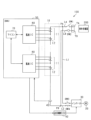
- the system 100 includes an assembled battery 10.
- the assembled battery 10 includes a series connection body of a plurality of battery modules 11 .
- Each battery module 11 comprises a series connection of a plurality of battery cells 12 .
- the number of battery cells 12 included in each battery module 11 is the same. However, the number of battery cells 12 included in each battery module 11 may be different.
- Each battery cell 12 is a rechargeable battery (secondary battery), specifically a lithium ion battery.
- the lithium ion storage battery of this embodiment is an LFP storage battery in which lithium iron phosphate is used as a positive electrode active material and graphite is used as a negative electrode active material.
- the rated voltage of each battery cell 12 constituting the battery module 11 is the same, and the rated capacity [Ah] of each battery cell 12 is the same.
- the system 100 includes a first charging path LA, a second charging path LB, a first external charging terminal TA, a second external charging terminal TB, a first switch SW1 and a second switch SW2.
- the first charging path LA connects the first external charging terminal TA and the positive terminal of the highest potential battery cell 12 constituting the assembled battery 10 .
- the second charging path LB connects the second external charging terminal TB to the negative terminal of the lowest potential battery cell 12 constituting the assembled battery 10 .
- a first switch SW1 is provided in the first charging path LA, and a second switch SW2 is provided in the second charging path LB.
- the assembled battery 10 is connected to the external charger 200 via the first and second external charging terminals TA, TB.
- External charger 200 is, for example, a DC quick charger.
- the external charger 200 is connected to the first and second external charging terminals TA and TB, the assembled battery 10 is charged with constant current or constant voltage by high-voltage DC power input from the external charger 200 .
- constant current charging is performed until just before the assembled battery 10 is fully charged, and then switching to constant voltage charging.
- the external charger 200 may be an AC charger instead of a DC charger.
- the system 100 includes a rotating electric machine 20, an inverter 30, a first electric path L1, a second electric path L2, a third switch SW3 and a fourth switch SW4.
- the first electrical path L1 connects a first connection point PA on the battery pack 10 side with respect to the first switch SW1 in the first charging path LA and the high potential side terminal of the inverter 30 .
- the second electrical path L2 connects a second connection point PB on the battery pack 10 side of the second charging path LB with respect to the second switch SW2 and the low potential side terminal of the inverter 30 .
- a third switch SW3 is provided on the first electrical path L1, and a fourth switch SW4 is provided on the second electrical path L2.
- the rotating electric machine 20 When the third switch SW3 and the fourth switch SW4 are turned on, the rotating electric machine 20 inputs and outputs electric power to and from the assembled battery 10 via the inverter 30 .
- the rotating electrical machine 20 applies propulsion force to the vehicle with electric power supplied from the assembled battery 10 during power running, and generates power using deceleration energy of the vehicle during regeneration, and supplies electric power to the assembled battery 10 .
- the system 100 includes a current sensor 40 and a BMU (Battery Management Unit) 50 as a battery monitoring device.
- the current sensor 40 detects current flowing through the assembled battery 10 .
- FIG. 1 shows that the current sensor 40 detects the current flowing through the second charging path LB.
- a value detected by the current sensor 40 is input to the BMU 50 .
- the BMU 50 turns on or off the first to fourth switches SW1 to SW4. Also, the BMU 50 is communicably connected to the traveling control ECU 42 via an in-vehicle network interface. The BMU 50 outputs a command for controlling the rotating electric machine 20 to the travel control ECU 42 based on the remaining capacity [Ah] of the assembled battery 10 . Based on a command from the BMU 50, the travel control ECU 42 performs switching control of the inverter 30 in order to control the control amount (for example, torque) of the rotary electric machine 20 to a command value.
- the control amount for example, torque
- the BMU 50 includes a monitoring IC 60 and a microcomputer 70 individually provided corresponding to each battery module 11 .
- the monitoring IC 60 detects the terminal voltage of each battery cell 12 forming the battery module 11 .
- Each monitoring IC 60 exchanges information with the microcomputer 70 .
- the microcomputer 70 acquires the terminal voltage detected by each monitoring IC 60 through an insulating element (not shown).
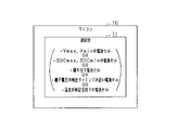
- the microcomputer 70 has a CPU.
- the functions provided by the microcomputer 70 can be provided by software recorded in a physical memory device, a computer executing the software, only software, only hardware, or a combination thereof.
- the microcomputer 70 executes a program stored in a non-transitory tangible storage medium as its own storage unit.
- the program includes, for example, a program for processing shown in FIG. 4 and the like. A method corresponding to the program is executed by executing the program.
- the storage unit is, for example, a non-volatile memory. Note that the program stored in the storage unit can be updated via a network such as the Internet, for example.
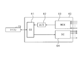
- the monitoring IC 60 includes a command section 61, an A/D converter 62, a switch section 63 and an equalization circuit section 64, as shown in FIG.
- the command section 61 has a function of interpreting commands from the microcomputer 70 .
- the switch section 63 has a function of arbitrarily selecting the voltage of each battery cell 12, and is, for example, a multiplexer.
- the A/D converter 62 converts the analog signal output from the switch section 63 into a digital signal.
- the converted digital signal is sent to the microcomputer 70 via the command section 61 .
- the microcomputer 70 acquires the terminal voltage of the battery cell 12 .
- the monitoring IC 60 performs processing according to commands from the microcomputer 70 by operating these units. For example, the monitoring IC 60 sequentially detects the terminal voltage of each battery cell 12 that constitutes the battery module 11 in a predetermined order.
- the equalization circuit unit 64 performs equalization processing for reducing voltage variations in each battery cell 12 that constitutes the battery module 11 based on a command from the microcomputer 70 .
- the equalization circuit section 64 is connected to each battery cell 12 .
- the equalization process is, for example, a process of discharging from the battery cell with the highest terminal voltage among the battery cells 12 . Note that, for example, when the microcomputer 70 determines that the difference between the highest voltage and the lowest voltage among the terminal voltage detection values of each battery cell 12 is equal to or greater than a predetermined voltage, the microcomputer 70 sends an equalization processing execution command to the monitoring IC 60. do it.
- a method for calculating the remaining capacity of the assembled battery 10 a method using SOC (State Of Charge) indicating the state of charge of the assembled battery 10 and the SOC-OCV characteristic indicating the correlation between the open circuit voltage (OCV) is known.
- SOC State Of Charge
- OCV open circuit voltage
- an LFP storage battery is used as the lithium ion storage battery.
- the OCV is stable over a wide range of remaining capacity, and has a plateau region SL where the change in OCV due to the change in capacity is small.
- the plateau region SL there are end regions SH where the change in OCV due to the change in capacitance is greater than that in the plateau region SL.
- a part of the plateau region SL is a specific region SB in which the change in OCV due to the change in capacitance is relatively large.
- the specific region SB is a region resulting from the negative electrode configuration of the battery cell 12 .
- the SOC of the battery cell 12 reaches a specific SOC or remaining capacity, the state of the battery cell 12 shifts to the specific region SB. Therefore, when the state of the battery cell 12 shifts to the specific area SB, it can be understood that the current SOC or remaining capacity of the battery cell 12 is the specific SOC or remaining capacity.
- the change in OCV is relatively large, the amount of change in OCV is small.
- the process shown in FIG. 4 is performed during charging of the assembled battery 10 by the charger 200 outside the vehicle, for example, in order to deal with this problem.
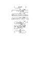
- FIG. 4 is a flowchart of SOC calculation processing of the battery cell 12 executed by the microcomputer 70.
- This process is repeatedly executed at a predetermined control cycle, for example, when it is determined that the state of the battery cell 12 is in the plateau region SL. Whether or not it is in the plateau region SL may be determined based on the terminal voltage of the battery cell acquired from the monitoring IC 60 .
- step S10 the terminal voltage of the first battery cell detected by the monitoring IC 60 (hereinafter referred to as first detection voltage V1d) and the terminal voltage of the second battery cell detected by the monitoring IC 60 (hereinafter referred to as second detection voltage V2d) and get.
- the first battery cell and the second battery cell are two battery cells selected from the battery cells 12 that constitute the battery module 11 . This selection method will be described in detail later.
- the process of step S10 corresponds to the "acquisition unit".
- step S11 the voltage difference ⁇ Vd (corresponding to "battery parameter") is calculated by subtracting the second detection voltage V2d from the first detection voltage V1d.
- step S12 it is determined whether or not the calculated voltage difference ⁇ Vd exceeds the determination value Vjde.
- step S12 If the determination in step S12 is affirmative, the process proceeds to step S13, and the SOCs of the first battery cell and the second battery cell are calculated as the specified value S ⁇ .
- the SOC of each battery cell 12 not limited to the first and second battery cells among the battery cells 12 constituting the battery module 11, may be calculated as the specified value S ⁇ , for example.
- the remaining capacities of the first and second battery cells may be calculated instead of the SOC.
- the processing of steps S11 to S13 corresponds to the "state calculation unit".
- FIG. 5(a) shows changes in the first and second detection voltages V1d and V2d
- FIG. 5(b) shows changes in the voltage difference ⁇ Vd
- FIG. 5(c) shows changes in the SOC of the first battery cell. show.
- the battery pack 10 is charged (constant current charging or constant voltage charging) by the external charger 200 .
- the state of the first battery cell shifts from the end region SH to the plateau region SL, and the rate of increase in terminal voltage associated with charging of the first battery cell slows down.
- the state of the second battery cell shifts from the end region SH to the plateau region SL, and the rate of increase in terminal voltage associated with charging of the second battery cell slows down. Since the first and second detection voltages V1d and V2d become equal after time t2, the voltage difference ⁇ Vd becomes a value close to zero.
- the SOCs of the first and second battery cells after time t1 are calculated by the microcomputer 70 based on, for example, the initial SOC based on the open-circuit voltage and the time integration value of the charging current flowing through the first and second battery cells. It is a calculated value.
- the microcomputer 70 determines that the voltage difference ⁇ Vd exceeds the determination value Vjde. Therefore, the microcomputer 70 calculates the SOC of the first and second battery cells as the specified value S ⁇ .
- the determination value Vjde is set to a value that allows it to be determined that the current control cycle is an intermediate timing between time t3 and time t6. Note that the SOCs of the first and second battery cells after time t4 are calculated by the microcomputer 70 based on, for example, the specified value S ⁇ and the time integrated value of the charging current flowing through the first and second battery cells. good.
- the state of the second battery cell shifts to the specific region SB, and the rising speed of the second detection voltage V2d temporarily increases from time t6 to t7. Since the first and second detection voltages V1d and V2d become equal after time t7, the voltage difference ⁇ Vd becomes a value close to zero. As a result, the rate of decrease in the voltage difference ⁇ Vd increases from time t6, and the voltage difference ⁇ Vd becomes a value close to 0 at time t7. Note that at time t8, the state of the first battery cell shifts to the end region SH.
- Noise is generated due to instantaneous changes in the current flowing through the battery pack 10 , and this noise can be superimposed on the terminal voltage detection value of each battery cell 12 .
- each battery cell 12 constituting the assembled battery 10 is connected in series. Therefore, it is considered that the effect of noise on the terminal voltage detection value of each battery cell 12 is the same. Therefore, the voltage difference ⁇ Vd, which is the difference between the terminal voltage detection values of the first and second battery cells, is a value with reduced influence of noise. Therefore, by using the voltage difference ⁇ Vd for estimating the SOC, it is possible to suppress deterioration in the calculation accuracy of the SOC even when noise occurs.
- an IC that can set the voltage detection range to either the entire voltage range that the battery cell 12 can take or a limited voltage range, which is a partial voltage range of the entire voltage range, may be used.
- the limited voltage range is selected as the voltage detection range, the voltage detection resolution is improved compared to when the full voltage range is selected as the voltage detection range.
- the limited voltage range is preferably set to, for example, the voltage range of the battery cells 12 included in the plateau region SL. In this case, the SOC calculation accuracy can be further improved.
- the microcomputer 70 sets the voltage detection range to the limited voltage range.
- the detected voltage is susceptible to noise.
- the microcomputer 70 may set the determination value Vjde larger as the variation in the SOC of each battery cell 12 at the start of charging of the assembled battery 10 increases. This setting is based on the fact that the peak value of the voltage difference ⁇ Vd increases as the variation in SOC increases.
- the microcomputer 70 may set the determination value Vjde larger as the temperatures of the first and second battery cells are higher or as the charging current detected by the current sensor 40 is smaller. This setting is based on the fact that the higher the temperature or the smaller the current, the larger the amount of increase in the detected voltage in the specific region SB.
- the selection unit 71 of the microcomputer 70 selects the battery cell with the highest terminal voltage detection value among the battery cells 12 as the first battery cell, and selects the battery cell with the lowest terminal voltage detection value. may be selected as the second battery cell. This is because, as shown in FIG. 7, the voltage difference ⁇ Vd in the specific region SB is increased to improve the calculation accuracy of the SOC.
- the selecting unit 71 may select the battery cell with the highest calculated SOC as the first battery cell from among the battery cells 12, and select the battery cell with the lowest calculated SOC as the second battery cell. .
- the selection unit 71 may select two battery cells connected in series and adjacent to each other among the battery cells 12 as the first battery cell and the second battery cell. Since the temperatures of two adjacent battery cells are close, it is possible to improve the accuracy of calculating the SOC based on the voltage difference ⁇ Vd.
- the first and second battery cells may be selected from all the battery cells 12 that make up the assembled battery 10, or may be selected from each of the battery cells 12 that make up each battery module 11. Alternatively, it may be selected from among the battery cells 12 to be monitored by the same monitoring IC 60 .
- the selection unit 71 may select the first and second battery cells from among the battery cells 12 to be AD-converted by the same A/D converter 62 . In this case, since the voltage detection error of the battery cell 12 to be AD-converted becomes a close value, the calculation accuracy of the SOC can be improved.
- the selection unit 71 may select two battery cells whose detection timing is close among the battery cells 12 forming the assembled battery 10 as the first and second battery cells. In this case, the noise that is superimposed on the terminal voltage detection values of the first and second battery cells has a similar value, so that the SOC calculation accuracy can be improved.
- the selection unit 71 may select the first and second battery cells from among the battery cells 12 forming the assembled battery 10, which are provided with temperature sensors (eg, thermistors). Further, the selection unit 71 may select, as the first and second battery cells, battery cells having a temperature equal to or less than a predetermined difference among the battery cells 12 forming the assembled battery 10 .
- temperature sensors eg, thermistors
- step S11 the voltage difference ⁇ Vd may be calculated by subtracting the first detection voltage V1d from the second detection voltage V2d.
- the processing in step S12 should be "
- FIG. 8 shows a flowchart of the SOC calculation process according to this embodiment. This process is repeatedly executed at a predetermined control cycle, for example, when the microcomputer 70 determines that the state of the battery cell 12 is in the plateau region SL.
- step S20 the first detection voltage V1d and the second detection voltage V2d are acquired.
- step S21 the voltage difference ⁇ Vd is calculated by subtracting the second detection voltage V2d from the first detection voltage V1d.
- step S22 it is determined whether or not the determination flag Fjde is 0.
- step S22 If it is determined in step S22 that the determination flag Fjde is 0, the process proceeds to step S23 to determine whether or not the calculated voltage difference ⁇ Vd exceeds the first determination value Vjde1. If a negative determination is made in step S23, the process proceeds to step S26.
- step S23 If the determination in step S23 is affirmative, the process proceeds to step S24, and the SOC of the first battery cell is calculated as the specified value S ⁇ . Note that in step S24, the remaining capacity of the first battery cell may be calculated instead of the SOC.
- step S24 After completing the process of step S24, the process proceeds to step S25 and sets the determination flag Fjde to 1. After that, the process proceeds to step S26.
- step S26 it is determined whether or not both the condition that the determination flag Fjde is 1 and the condition that the calculated voltage difference ⁇ Vd is less than the second determination value Vjde2 are satisfied.
- the second determination value Vjde2 is set to a value smaller than the first determination value Vjde1.
- the second determination value Vjde2 is not limited to this, and may be set to a value greater than the first determination value Vjde1 or the same value as the first determination value Vjde1.
- step S26 If the determination in step S26 is affirmative, the process proceeds to step S27, and the SOC of the second battery cell is calculated as the specified value S ⁇ . In step S27, the remaining capacity of the second battery cell may be calculated instead of the SOC.
- FIG. 9A and 9B correspond to FIGS. 5A and 5B.
- the battery pack 10 is charged (constant current charging or constant voltage charging) by the external charger 200 .
- the state of the first battery cell shifts from the end region SH to the plateau region SL
- the state of the second battery cell shifts from the end region SH to the plateau region SL. Since the first and second detection voltages V1d and V2d become equal after time t2, the voltage difference ⁇ Vd becomes a value close to zero.
- the state of the first battery cell shifts to the specific region SB, and the rising speed of the first detection voltage V1d temporarily increases from time t3 to t5.
- the state of the second battery cell is still within the plateau region SL. Therefore, after time t3, the voltage difference ⁇ Vd increases, and at time t4, the microcomputer 70 determines that the voltage difference ⁇ Vd has exceeded the first determination value Vjde1. Therefore, the microcomputer 70 calculates the SOC of the first battery cell as the prescribed value S ⁇ .
- the state of the second battery cell shifts to the specific region SB, and the rising speed of the second detection voltage V2d temporarily increases from time t6 to t8.
- the microcomputer 70 determines that the voltage difference ⁇ Vd has fallen below the second determination value Vjde2. Therefore, the microcomputer 70 calculates the SOC of the second battery cell as the specified value S ⁇ .
- the state of the first battery cell shifts to the end region SH.
- the SOCs of the first and second battery cells can be calculated individually.
- FIG. 10 shows a flowchart of the SOC calculation process according to this embodiment. This process is repeatedly executed at a predetermined control cycle, for example, when the microcomputer 70 determines that the state of the battery cell 12 is in the plateau region SL.
- step S30 the first detected voltage V1d(t) and the second detected voltage V2d(t) are obtained.
- step S31 the voltage difference ⁇ Vd( t) is calculated.
- step S32 the voltage difference ⁇ Vd(t ⁇ 1) calculated in the previous control cycle is subtracted from the voltage difference ⁇ Vd(t) calculated in the current control cycle to calculate the voltage time change amount ⁇ Ad.
- step S33 it is determined whether or not the voltage time change amount ⁇ Ad crosses 0.
- step S33 determines whether the determination in step S33 is affirmative. If the determination in step S33 is affirmative, the process proceeds to step S34 to calculate the SOC of the first battery cell and the second battery cell as the specified value S ⁇ . In step S34, the remaining capacity of the first and second battery cells may be calculated instead of the SOC.
- FIG. 11(a) and 11(b) correspond to FIGS. 5(a) and 5(b), and FIG. 11(c) shows the transition of the voltage time variation ⁇ Ad.
- the battery pack 10 is charged (constant current charging or constant voltage charging) by the external charger 200 .
- the state of the first battery cell shifts from the end region SH to the plateau region SL
- the state of the second battery cell shifts from the end region SH to the plateau region SL.
- the first and second detection voltages V1d and V2d become equal, so the voltage difference ⁇ Vd becomes a value close to 0, and the voltage time change amount ⁇ Ad becomes 0 or a positive value close to 0.
- the voltage time change amount ⁇ Ad becomes 0 or a positive value close to 0.
- the state of the second battery cell shifts to the specific region SB, and the rising speed of the second detection voltage V2d temporarily increases from time t5 to t6.
- the voltage time change amount ⁇ Ad greatly changes to the negative side.
- the microcomputer 70 determines that the voltage time change amount ⁇ Ad straddles zero. Therefore, the microcomputer 70 calculates the SOC of the first and second battery cells as the specified value S ⁇ .
- the microcomputer 70 calculates the SOCs of the first and second battery cells as the specified value S ⁇ at time t4 when the voltage time variation amount ⁇ Ad is greatly reduced to a value close to 0, for example. good.
- (A) ( ⁇ Vd(tm)- ⁇ Vd(tm-1))/ ⁇ Ca ⁇ Ca indicates the amount of change in capacity [Ah] of the battery cell during a specified period from time tm-1 to time tm.
- the prescribed period is, for example, one control period of the microcomputer 70 or a period longer than one control period.
- the specified period can also be set as a period required for the amount of capacitance change ⁇ Ca to reach a predetermined amount of capacitance change, for example.
- ⁇ Vd(tm-1) is a value obtained by subtracting the second detection voltage V2d obtained at time tm-1 from the first detection voltage V1d obtained at time tm-1.
- ⁇ Vd(tm) is a value obtained by subtracting the second detection voltage V2d obtained at time tm from the first detection voltage V1d obtained at time tm.
- (B) ( ⁇ Vd(tm)- ⁇ Vd(tm-1))/ ⁇ SOC ⁇ SOC indicates the amount of change in the SOC of the battery cell during a specified period from time tm ⁇ 1 to time tm.
- the prescribed period in this case can be set, for example, as a period required for the SOC change amount ⁇ SOC to reach a predetermined SOC change amount, as described above.
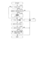
- FIG. 12 shows a flowchart of the processing for calculating the remaining capacity difference. This process is repeatedly executed at a predetermined control cycle, for example, when the microcomputer 70 determines that the state of the battery cell 12 is in the plateau region SL.
- step S40 the first detection voltage V1d and the second detection voltage V2d are acquired.
- step S41 the voltage difference ⁇ Vd is calculated by subtracting the second detection voltage V2d from the first detection voltage V1d.
- step S42 it is determined whether or not the determination flag Fjde is 0. If it is determined in step S42 that the determination flag Fjde is 0, the process proceeds to step S43 to determine whether or not the calculated voltage difference ⁇ Vd exceeds the first determination value Vjde1. If an affirmative determination is made in step S43, that is, if it is determined that the voltage difference ⁇ Vd changes in the positive direction and crosses over the first determination value Vjde1, the process proceeds to step S44, where the charging current time detected by the current sensor 40 is Start calculating the integrated value. After the processing of step S44 is completed, the process proceeds to step S45 and sets the determination flag Fjde to 1. After that, the process proceeds to step S46.
- step S46 it is determined whether or not both the first condition that the determination flag Fjde is 1 and the second condition that the calculated voltage difference ⁇ Vd is lower than the second determination value Vjde2 are satisfied.
- the second condition is a condition that the voltage difference ⁇ Vd changes in the negative direction and straddles the second determination value Vjde2.
- step S46 If an affirmative determination is made in step S46, the process proceeds to step S47, sets the determination flag Fjde to 0, and terminates the current integration process started in step S44.
- step S47 the time integrated value of the charging current calculated by the current integration process is calculated as the difference in remaining capacity between the first and second battery cells. Note that the difference in SOC between the first and second battery cells may be calculated based on the difference in remaining capacity.
- FIG. 13(c) shows the transition of the determination flag Fjde
- FIG. 13(d) shows the transition of the time integrated value of the charging current
- FIG. 13(e) shows the difference in remaining capacity between the first and second battery cells. shows the transition of the calculated value of
- the battery pack 10 is charged (constant current charging or constant voltage charging) by the external charger 200 .
- the state of the first battery cell shifts from the end region SH to the plateau region SL
- the state of the second battery cell shifts from the end region SH to the plateau region SL.
- the microcomputer 70 determines that the voltage difference ⁇ Vd has exceeded the first determination value Vjde1. Therefore, the determination flag Fjde is set to 1, and charging current integration processing is started.
- the microcomputer 70 determines that the voltage difference ⁇ Vd has fallen below the second determination value Vjde2. Therefore, the determination flag Fjde is set to 0, and the charging current integration process ends. Then, the value of the charging current accumulated from time t4 to t7 is calculated as the difference in remaining capacity between the first and second battery cells.
- the microcomputer 70 may determine that at least one of the first and second battery cells is out of order when determining that the calculated remaining capacity difference is equal to or greater than a predetermined capacity. Further, the microcomputer 70 may determine the discharge amount of the battery cell in the equalization process based on the calculated difference in remaining capacity.
- step S14 it is determined whether or not the charging start flag Fchr is 0.
- the charging start flag Fchr it indicates that the charging of the assembled battery 10 has not yet started, and when it is 1, it indicates that the charging has already started.
- the process proceeds to step S10.
- step S14 determines whether the charging start flag Fchr is 0, the process proceeds to step S15, and the SOC of the first battery cell (hereinafter referred to as SOC1) and the SOC of the second battery cell (hereinafter referred to as SOC2) are is greater than the threshold value Sth.
- SOC1 and SOC2 correspond to the "storage amount parameter".
- the stored electricity amount parameters are not limited to SOC1 and SOC2, and may be, for example, the first and second detection voltages V1d and V2d, or the remaining capacities of the first and second battery cells.
- step S15 the process proceeds to step S17, and discharge processing is performed to discharge from either the first or second battery cell.
- the second battery cell is discharged.
- the equalization circuit section 64 may be used for this discharge. This discharging continues until an affirmative determination is made in step S15.
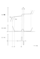
- FIG. 15(a) shows transitions of SOC1 and SOC2
- FIG. 15(b) shows whether or not the discharge process of the second battery cell is executed.
- FIGS. 15(c) and (d) correspond to FIGS. 5(a) and (b).
- the microcomputer 70 determines that the absolute value of the difference between SOC1 and SOC2 is equal to or less than the threshold value Sth. Therefore, the discharge process is executed by the microcomputer 70 until time t2 when it is determined that this absolute value exceeds the threshold value Sth. After that, charging of the assembled battery 10 is started, and the SOC estimation process is executed. At time t3, microcomputer 70 determines that voltage difference ⁇ Vd has exceeded determination value Vjde, and calculates the SOC of the first battery cell as specified value S ⁇ .
- the voltage difference ⁇ Vd calculated in the SOC calculation process becomes small, and there is a concern that the accuracy of SOC calculation will decrease. Therefore, in the present embodiment, discharge processing is performed prior to SOC calculation processing. As a result, the SOC calculation process can be started with the difference between the SOC1 and the SOC2 increased, and a decrease in the accuracy of the SOC calculation can be avoided.
- the time to perform the discharge process for increasing the difference between SOC1 and SOC2 is not limited to before the battery pack 10 is charged.
- the microcomputer 70 calculates the absolute value of the difference between the SOC1 and the SOC2 each time during the charging of the assembled battery 10, and if it determines that the calculated absolute value is equal to or less than the threshold value Sth, while charging the assembled battery 10 You may perform the process of step S17.
- the threshold value Sth is set to the first threshold value Sth1, and the second threshold value Sth2 is set to a value larger than the first threshold value Sth1.
- the microcomputer 70 performs discharge processing over a period from when the absolute value of the difference between the SOC1 and SOC2 is determined to be equal to or less than the first threshold value Sth1 to when the absolute value is determined to be equal to or greater than the second threshold value Sth2. may be executed.
- one of the first and second battery cells is charged during the period from when the negative determination is made in step S15 to when the positive determination is made in step S15. You may change to the charge process which does.
- the difference in SOC between the first battery cell and the second battery cell may be increased by performing the discharging process on one of the first and second battery cells and the charging process on the other.
- the amount of reaction heat WR changes when the remaining capacity changes with energization.
- the reaction heat amount WR is obtained by subtracting the Joule heat WJ due to the impedance component of the storage battery from the heat generation amount WB of the storage battery due to energization.
- the amount of reaction heat WR is expressed by the following equation (2) using the temperature TM of the storage battery, the charging/discharging current IS, and the amount of voltage change ⁇ OCV, which is the amount of change in the open-circuit voltage OCV per unit temperature.
- the amount of reaction heat WR is proportional to the amount of voltage change ⁇ OCV.
- the amount of voltage change ⁇ OCV has a value for each capacity of the storage battery, and there are storage batteries in which the amount of voltage change ⁇ OCV changes when the capacity changes.
- the reaction heat amount WR changes, so the temperature TM changes.
- the temperature TM and the impedance have a correlation. Therefore, when the temperature TM of the storage battery changes, the impedance of the storage battery changes.
- FIG. 16 shows the relationship between the remaining capacity of the battery cell 12 of this embodiment and the voltage change amount ⁇ OCV.
- the battery cell 12 has a specific capacity region from a first capacity QA to a second capacity QB, and the specific capacity region is included in a plateau region SL.
- the voltage change amount ⁇ OCV rapidly increases, and when the remaining capacity crosses the second capacitor QB from the low capacity side, the voltage change amount ⁇ OCV sharply decreases.
- the first and second capacities QA and QB since the change in the voltage change amount ⁇ OCV is steep, the tendency of the impedance transition of the battery cell 12 during energization increases by crossing the first and second capacities QA and QB. Change.
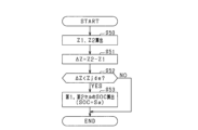
- FIG. 17 shows SOC calculation processing focused on this point. This process is repeatedly executed at a predetermined control cycle, for example, when the microcomputer 70 determines that the state of the battery cell 12 is in the plateau region SL.
- step S50 the impedance Z1 of the first battery cell and the impedance Z2 of the second battery cell are calculated.
- the amount of change ⁇ V1 in the first detection voltage V1d when the charging current flowing through the first battery cell changes during charging of the assembled battery 10 is divided by the amount of change ⁇ IS in the charging current. By doing so, the impedance Z1 of the first battery cell is calculated.
- step S51 the impedance difference ⁇ Z is calculated by subtracting the impedance Z1 of the first battery cell from the impedance Z2 of the second battery cell.
- the impedance difference ⁇ Z is a value with reduced influence of noise.
- step S52 it is determined whether or not the impedance difference ⁇ Z is below the determination value Zjde.
- step S53 the process proceeds to step S53 to calculate the SOC of the first battery cell and the second battery cell as the specified value S ⁇ .
- step S53 the remaining capacity of the first and second battery cells may be calculated instead of the SOC.
- FIG. 18(a) shows changes in the impedances Z1 and Z2 of the first and second battery cells
- FIG. 18(b) shows changes in the impedance difference ⁇ Z.
- the assembled battery 10 is charged by the external charger 200 .
- the impedance difference ⁇ Z is substantially constant until time t1.
- impedance difference ⁇ Z begins to decrease, and at time t2, microcomputer 70 determines that impedance difference ⁇ Z has fallen below determination value Zjde. Therefore, the microcomputer 70 calculates the SOC of the first and second battery cells as the specified value S ⁇ .
- the impedance of the second battery cell ceases to drop significantly, and the impedance difference ⁇ Z thereafter becomes substantially constant.
- the microcomputer 70 may calculate the SOC of the first battery cell as the specified value S ⁇ at time t1, and may calculate the SOC of the second battery cell as the specified value S ⁇ at time t2.
- the impedance difference ⁇ Z may be used instead of the voltage difference ⁇ Vd.
- the controller and techniques described in this disclosure can be performed by a dedicated computer provided by configuring a processor and memory programmed to perform one or more functions embodied by a computer program; may be implemented.
- the controls and techniques described in this disclosure may be implemented by a dedicated computer provided by configuring the processor with one or more dedicated hardware logic circuits.
- the control units and techniques described in this disclosure can be implemented by a combination of a processor and memory programmed to perform one or more functions and a processor configured by one or more hardware logic circuits. It may also be implemented by one or more dedicated computers configured.
- the computer program may also be stored as computer-executable instructions on a computer-readable non-transitional tangible recording medium.
Landscapes
- Physics & Mathematics (AREA)
- General Physics & Mathematics (AREA)
- Engineering & Computer Science (AREA)
- Chemical & Material Sciences (AREA)
- Chemical Kinetics & Catalysis (AREA)
- Electrochemistry (AREA)
- General Chemical & Material Sciences (AREA)
- Manufacturing & Machinery (AREA)
- Power Engineering (AREA)
- Secondary Cells (AREA)
- Inorganic Chemistry (AREA)
- Materials Engineering (AREA)
- Charge And Discharge Circuits For Batteries Or The Like (AREA)
- Battery Electrode And Active Subsutance (AREA)
- Tests Of Electric Status Of Batteries (AREA)
Priority Applications (3)
| Application Number | Priority Date | Filing Date | Title |
|---|---|---|---|
| DE112022003719.9T DE112022003719T5 (de) | 2021-07-27 | 2022-06-27 | Batterieüberwachungsvorrichtung und Programm |
| CN202280051522.7A CN117716246A (zh) | 2021-07-27 | 2022-06-27 | 电池监视装置和程序 |
| US18/423,449 US20240159835A1 (en) | 2021-07-27 | 2024-01-26 | Battery monitoring device and program |
Applications Claiming Priority (2)
| Application Number | Priority Date | Filing Date | Title |
|---|---|---|---|
| JP2021122816A JP7632155B2 (ja) | 2021-07-27 | 2021-07-27 | 電池監視装置、及びプログラム |
| JP2021-122816 | 2021-07-27 |
Related Child Applications (1)
| Application Number | Title | Priority Date | Filing Date |
|---|---|---|---|
| US18/423,449 Continuation US20240159835A1 (en) | 2021-07-27 | 2024-01-26 | Battery monitoring device and program |
Publications (1)
| Publication Number | Publication Date |
|---|---|
| WO2023008044A1 true WO2023008044A1 (ja) | 2023-02-02 |
Family
ID=85087927
Family Applications (1)
| Application Number | Title | Priority Date | Filing Date |
|---|---|---|---|
| PCT/JP2022/025570 Ceased WO2023008044A1 (ja) | 2021-07-27 | 2022-06-27 | 電池監視装置、及びプログラム |
Country Status (5)
| Country | Link |
|---|---|
| US (1) | US20240159835A1 (https=) |
| JP (1) | JP7632155B2 (https=) |
| CN (1) | CN117716246A (https=) |
| DE (1) | DE112022003719T5 (https=) |
| WO (1) | WO2023008044A1 (https=) |
Cited By (1)
| Publication number | Priority date | Publication date | Assignee | Title |
|---|---|---|---|---|
| CN121276384A (zh) * | 2025-12-09 | 2026-01-06 | 重庆市设计院有限公司 | 一种储能设施安全预警保护方法及系统 |
Families Citing this family (3)
| Publication number | Priority date | Publication date | Assignee | Title |
|---|---|---|---|---|
| JP7690075B1 (ja) * | 2024-02-02 | 2025-06-09 | レノボ・シンガポール・プライベート・リミテッド | 二次電池及び容量計算装置 |
| JP2026001796A (ja) * | 2024-06-20 | 2026-01-08 | 株式会社デンソー | 電池制御装置及びプログラム |
| CN118671617B (zh) * | 2024-07-09 | 2024-11-12 | 香港科技大学(广州) | 电池的电解液化成反应分析方法及相关设备 |
Citations (8)
| Publication number | Priority date | Publication date | Assignee | Title |
|---|---|---|---|---|
| US20100225325A1 (en) * | 2009-03-03 | 2010-09-09 | Robert Bosch Gmbh | Battery System and Method for System State of Charge Determination |
| JP2011034784A (ja) * | 2009-07-31 | 2011-02-17 | Sanyo Electric Co Ltd | 二次電池装置 |
| US20140049222A1 (en) * | 2011-03-07 | 2014-02-20 | A123 Systems, Inc | Method for Opportunistically Balancing Charge Between Battery Cells |
| US20190305384A1 (en) * | 2016-12-23 | 2019-10-03 | Huawei Technologies Co., Ltd. | Battery micro-short circuit detection method and apparatus |
| WO2020021889A1 (ja) * | 2018-07-25 | 2020-01-30 | パナソニックIpマネジメント株式会社 | 管理装置、及び電源システム |
| JP2020063983A (ja) * | 2018-10-17 | 2020-04-23 | 横河電機株式会社 | バッテリマネジメントシステム、バッテリマネジメント方法およびバッテリマネジメントプログラム |
| JP2020074258A (ja) * | 2017-03-01 | 2020-05-14 | ヤマハ発動機株式会社 | 充電装置 |
| JP2021027031A (ja) * | 2019-08-01 | 2021-02-22 | 株式会社デンソー | 二次電池の劣化度判定装置及び組電池 |
Family Cites Families (3)
| Publication number | Priority date | Publication date | Assignee | Title |
|---|---|---|---|---|
| DE112016003166B4 (de) | 2015-07-13 | 2019-05-23 | Mitsubishi Electric Corporation | Verfahren zum schätzen des ladezustandes für eine lithium-ionen-batterie und ladezustands-schätzvorrichtung für eine lithium-ionen-batterie |
| WO2018012364A1 (ja) | 2016-07-13 | 2018-01-18 | 株式会社 村田製作所 | 組電池回路、容量係数検出方法、および容量係数検出プログラム |
| JP2021122816A (ja) | 2020-02-10 | 2021-08-30 | Nde株式会社 | 光触媒反応器 |
-
2021
- 2021-07-27 JP JP2021122816A patent/JP7632155B2/ja active Active
-
2022
- 2022-06-27 DE DE112022003719.9T patent/DE112022003719T5/de active Pending
- 2022-06-27 WO PCT/JP2022/025570 patent/WO2023008044A1/ja not_active Ceased
- 2022-06-27 CN CN202280051522.7A patent/CN117716246A/zh active Pending
-
2024
- 2024-01-26 US US18/423,449 patent/US20240159835A1/en active Pending
Patent Citations (8)
| Publication number | Priority date | Publication date | Assignee | Title |
|---|---|---|---|---|
| US20100225325A1 (en) * | 2009-03-03 | 2010-09-09 | Robert Bosch Gmbh | Battery System and Method for System State of Charge Determination |
| JP2011034784A (ja) * | 2009-07-31 | 2011-02-17 | Sanyo Electric Co Ltd | 二次電池装置 |
| US20140049222A1 (en) * | 2011-03-07 | 2014-02-20 | A123 Systems, Inc | Method for Opportunistically Balancing Charge Between Battery Cells |
| US20190305384A1 (en) * | 2016-12-23 | 2019-10-03 | Huawei Technologies Co., Ltd. | Battery micro-short circuit detection method and apparatus |
| JP2020074258A (ja) * | 2017-03-01 | 2020-05-14 | ヤマハ発動機株式会社 | 充電装置 |
| WO2020021889A1 (ja) * | 2018-07-25 | 2020-01-30 | パナソニックIpマネジメント株式会社 | 管理装置、及び電源システム |
| JP2020063983A (ja) * | 2018-10-17 | 2020-04-23 | 横河電機株式会社 | バッテリマネジメントシステム、バッテリマネジメント方法およびバッテリマネジメントプログラム |
| JP2021027031A (ja) * | 2019-08-01 | 2021-02-22 | 株式会社デンソー | 二次電池の劣化度判定装置及び組電池 |
Cited By (1)
| Publication number | Priority date | Publication date | Assignee | Title |
|---|---|---|---|---|
| CN121276384A (zh) * | 2025-12-09 | 2026-01-06 | 重庆市设计院有限公司 | 一种储能设施安全预警保护方法及系统 |
Also Published As
| Publication number | Publication date |
|---|---|
| JP2023018592A (ja) | 2023-02-08 |
| JP7632155B2 (ja) | 2025-02-19 |
| CN117716246A (zh) | 2024-03-15 |
| US20240159835A1 (en) | 2024-05-16 |
| DE112022003719T5 (de) | 2024-05-08 |
Similar Documents
| Publication | Publication Date | Title |
|---|---|---|
| JP7632155B2 (ja) | 電池監視装置、及びプログラム | |
| JP6179407B2 (ja) | 組電池の均等化装置及び方法 | |
| JP6217996B2 (ja) | 蓄電素子の充放電システム | |
| CN107533109B (zh) | 电池控制装置以及电动车辆系统 | |
| JP6634854B2 (ja) | 蓄電素子管理装置、蓄電素子管理方法、蓄電素子モジュール、蓄電素子管理プログラム及び移動体 | |
| JP5819443B2 (ja) | 電池制御装置、電池システム | |
| JP6032473B2 (ja) | 状態管理装置、蓄電素子の均等化方法 | |
| CN103548233B (zh) | 蓄电器控制电路 | |
| JP5929778B2 (ja) | 充電率推定装置および充電率推定方法 | |
| JP2016151513A (ja) | 電池システム監視装置 | |
| JP2014077681A (ja) | 蓄電素子の充放電可能電力推定装置、蓄電装置、および充放電可能電力推定方法 | |
| EP3323184A1 (en) | A method and system for balancing a battery pack | |
| JP6489366B2 (ja) | 組電池の監視装置、組電池の容量均等化方法。 | |
| JP6855835B2 (ja) | 電池満充電容量推定装置 | |
| JP6155743B2 (ja) | 充電状態検出装置および充電状態検出方法 | |
| JP5381303B2 (ja) | 組電池の容量調整装置 | |
| JP2018050416A (ja) | バッテリシステム | |
| US20230058220A1 (en) | Cell equalization system | |
| JP2019144211A (ja) | 推定装置および推定方法 | |
| WO2013057784A1 (ja) | 電池制御装置、二次電池システム | |
| US12119683B2 (en) | Battery management device and battery device | |
| JP6135898B2 (ja) | 蓄電素子の充電制御装置、蓄電装置および充電制御方法 | |
| JP7027860B2 (ja) | 電源システム | |
| JP2022096471A (ja) | 電池監視装置 | |
| JP5772615B2 (ja) | 蓄電システム |
Legal Events
| Date | Code | Title | Description |
|---|---|---|---|
| 121 | Ep: the epo has been informed by wipo that ep was designated in this application |
Ref document number: 22849114 Country of ref document: EP Kind code of ref document: A1 |
|
| WWE | Wipo information: entry into national phase |
Ref document number: 202280051522.7 Country of ref document: CN |
|
| 122 | Ep: pct application non-entry in european phase |
Ref document number: 22849114 Country of ref document: EP Kind code of ref document: A1 |