WO2023008044A1 - Battery monitoring device and program - Google Patents
Battery monitoring device and program Download PDFInfo
- Publication number
- WO2023008044A1 WO2023008044A1 PCT/JP2022/025570 JP2022025570W WO2023008044A1 WO 2023008044 A1 WO2023008044 A1 WO 2023008044A1 JP 2022025570 W JP2022025570 W JP 2022025570W WO 2023008044 A1 WO2023008044 A1 WO 2023008044A1
- Authority
- WO
- WIPO (PCT)
- Prior art keywords
- battery
- battery cell
- difference
- soc
- cell
- Prior art date
Links
Images


Classifications
-
- G—PHYSICS
- G01—MEASURING; TESTING
- G01R—MEASURING ELECTRIC VARIABLES; MEASURING MAGNETIC VARIABLES
- G01R31/00—Arrangements for testing electric properties; Arrangements for locating electric faults; Arrangements for electrical testing characterised by what is being tested not provided for elsewhere
- G01R31/36—Arrangements for testing, measuring or monitoring the electrical condition of accumulators or electric batteries, e.g. capacity or state of charge [SoC]
- G01R31/378—Arrangements for testing, measuring or monitoring the electrical condition of accumulators or electric batteries, e.g. capacity or state of charge [SoC] specially adapted for the type of battery or accumulator
-
- G—PHYSICS
- G01—MEASURING; TESTING
- G01R—MEASURING ELECTRIC VARIABLES; MEASURING MAGNETIC VARIABLES
- G01R31/00—Arrangements for testing electric properties; Arrangements for locating electric faults; Arrangements for electrical testing characterised by what is being tested not provided for elsewhere
- G01R31/36—Arrangements for testing, measuring or monitoring the electrical condition of accumulators or electric batteries, e.g. capacity or state of charge [SoC]
- G01R31/382—Arrangements for monitoring battery or accumulator variables, e.g. SoC
-
- G—PHYSICS
- G01—MEASURING; TESTING
- G01R—MEASURING ELECTRIC VARIABLES; MEASURING MAGNETIC VARIABLES
- G01R31/00—Arrangements for testing electric properties; Arrangements for locating electric faults; Arrangements for electrical testing characterised by what is being tested not provided for elsewhere
- G01R31/36—Arrangements for testing, measuring or monitoring the electrical condition of accumulators or electric batteries, e.g. capacity or state of charge [SoC]
- G01R31/385—Arrangements for measuring battery or accumulator variables
- G01R31/387—Determining ampere-hour charge capacity or SoC
- G01R31/388—Determining ampere-hour charge capacity or SoC involving voltage measurements
-
- G—PHYSICS
- G01—MEASURING; TESTING
- G01R—MEASURING ELECTRIC VARIABLES; MEASURING MAGNETIC VARIABLES
- G01R31/00—Arrangements for testing electric properties; Arrangements for locating electric faults; Arrangements for electrical testing characterised by what is being tested not provided for elsewhere
- G01R31/36—Arrangements for testing, measuring or monitoring the electrical condition of accumulators or electric batteries, e.g. capacity or state of charge [SoC]
- G01R31/396—Acquisition or processing of data for testing or for monitoring individual cells or groups of cells within a battery
-
- H—ELECTRICITY
- H01—ELECTRIC ELEMENTS
- H01M—PROCESSES OR MEANS, e.g. BATTERIES, FOR THE DIRECT CONVERSION OF CHEMICAL ENERGY INTO ELECTRICAL ENERGY
- H01M10/00—Secondary cells; Manufacture thereof
- H01M10/05—Accumulators with non-aqueous electrolyte
- H01M10/052—Li-accumulators
- H01M10/0525—Rocking-chair batteries, i.e. batteries with lithium insertion or intercalation in both electrodes; Lithium-ion batteries
-
- H—ELECTRICITY
- H01—ELECTRIC ELEMENTS
- H01M—PROCESSES OR MEANS, e.g. BATTERIES, FOR THE DIRECT CONVERSION OF CHEMICAL ENERGY INTO ELECTRICAL ENERGY
- H01M10/00—Secondary cells; Manufacture thereof
- H01M10/42—Methods or arrangements for servicing or maintenance of secondary cells or secondary half-cells
- H01M10/48—Accumulators combined with arrangements for measuring, testing or indicating the condition of cells, e.g. the level or density of the electrolyte
-
- H—ELECTRICITY
- H01—ELECTRIC ELEMENTS
- H01M—PROCESSES OR MEANS, e.g. BATTERIES, FOR THE DIRECT CONVERSION OF CHEMICAL ENERGY INTO ELECTRICAL ENERGY
- H01M4/00—Electrodes
- H01M4/02—Electrodes composed of, or comprising, active material
- H01M4/36—Selection of substances as active materials, active masses, active liquids
- H01M4/58—Selection of substances as active materials, active masses, active liquids of inorganic compounds other than oxides or hydroxides, e.g. sulfides, selenides, tellurides, halogenides or LiCoFy; of polyanionic structures, e.g. phosphates, silicates or borates
-
- H—ELECTRICITY
- H02—GENERATION; CONVERSION OR DISTRIBUTION OF ELECTRIC POWER
- H02J—CIRCUIT ARRANGEMENTS OR SYSTEMS FOR SUPPLYING OR DISTRIBUTING ELECTRIC POWER; SYSTEMS FOR STORING ELECTRIC ENERGY
- H02J7/00—Circuit arrangements for charging or depolarising batteries or for supplying loads from batteries
- H02J7/02—Circuit arrangements for charging or depolarising batteries or for supplying loads from batteries for charging batteries from ac mains by converters
-
- Y—GENERAL TAGGING OF NEW TECHNOLOGICAL DEVELOPMENTS; GENERAL TAGGING OF CROSS-SECTIONAL TECHNOLOGIES SPANNING OVER SEVERAL SECTIONS OF THE IPC; TECHNICAL SUBJECTS COVERED BY FORMER USPC CROSS-REFERENCE ART COLLECTIONS [XRACs] AND DIGESTS
- Y02—TECHNOLOGIES OR APPLICATIONS FOR MITIGATION OR ADAPTATION AGAINST CLIMATE CHANGE
- Y02E—REDUCTION OF GREENHOUSE GAS [GHG] EMISSIONS, RELATED TO ENERGY GENERATION, TRANSMISSION OR DISTRIBUTION
- Y02E60/00—Enabling technologies; Technologies with a potential or indirect contribution to GHG emissions mitigation
- Y02E60/10—Energy storage using batteries
Definitions
- the present disclosure relates to a battery monitoring device and a program.
- Patent Document 1 the amount of voltage change due to the capacity change of the storage battery is relatively large in some regions of the plateau region, and the voltage change amount due to the capacity change is relatively large in the other regions. It is described that there are battery characteristics that are substantially constant, and that there are battery characteristics in which a phenomenon in which the amount of voltage change accompanying a change in capacity increases occurs at a specific SOC. Patent Literature 1 describes a state-of-charge estimation device that estimates the SOC of a storage battery using such characteristics. Specifically, the estimating device calculates the time rate of change of the terminal voltage detection value of the storage battery when the state of the storage battery being charged or discharged is in the plateau region. The estimating device estimates that the current SOC of the storage battery is the SOC linked in advance to the calculated rate of change with time when it is determined that the calculated rate of change with time is an upwardly convex inflection point.
- the absolute value of the amount of voltage change is small. Therefore, if noise is superimposed on the terminal voltage detection value of the storage battery, there is a concern that the calculation accuracy of the SOC may be greatly reduced.
- the main purpose of the present disclosure is to provide an electric machine monitoring device and a program that can suppress deterioration in the accuracy of battery state calculation.
- the present disclosure is applied to an assembled battery including a plurality of battery cells connected in series, an acquisition unit that acquires a battery parameter that is either terminal voltage or impedance of a first battery cell and a second battery cell among the battery cells during charging or discharging of the battery cells; State calculation for calculating a difference between the obtained battery parameter of the first battery cell and the obtained battery parameter of the second battery cell, and calculating the battery state of the battery cell based on the calculated difference and
- a plurality of battery cells that make up an assembled battery are connected in series. Therefore, when either the terminal voltage or the impedance is used as the battery parameter, it is considered that the effect of noise on the battery parameter of each battery cell is the same. Therefore, the difference between the battery parameters of two battery cells among the battery cells constituting the assembled battery is a value with reduced influence of noise.
- the state calculation unit of the present disclosure calculates the difference between the acquired battery parameter of the first battery cell and the acquired battery parameter of the second battery cell, and based on the calculated difference, Calculate battery status. As a result, it is possible to suppress a decrease in accuracy in calculating the battery state.
- FIG. 1 is an overall configuration diagram of the system according to the first embodiment
- FIG. 2 is a diagram showing the configuration of the monitoring IC
- FIG. 3 is a diagram showing the relationship between the voltage and capacity of the battery cell
- FIG. 4 is a flowchart showing the procedure of the SOC calculation process
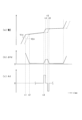
- FIG. 5 is a time chart showing changes in the terminal voltage, voltage difference, and SOC of the battery cell during charging
- FIG. 6 is a diagram showing a selection unit of a microcomputer according to a modification of the first embodiment
- FIG. 7 is a time chart showing changes in terminal voltages of battery cells with the highest and lowest terminal voltages
- FIG. 1 is an overall configuration diagram of the system according to the first embodiment
- FIG. 2 is a diagram showing the configuration of the monitoring IC
- FIG. 3 is a diagram showing the relationship between the voltage and capacity of the battery cell
- FIG. 4 is a flowchart showing the procedure of the SOC calculation process
- FIG. 5 is a time chart showing changes in the terminal voltage, voltage difference,
- FIG. 8 is a flowchart showing the procedure of SOC calculation processing according to the second embodiment
- FIG. 9 is a time chart showing changes in terminal voltage and voltage difference of battery cells during charging
- FIG. 10 is a flowchart showing the procedure of SOC calculation processing according to the third embodiment
- FIG. 11 is a time chart showing changes in terminal voltage, voltage difference, and voltage time change of a battery cell during charging
- FIG. 12 is a flowchart showing the procedure of capacitance difference calculation processing according to the fourth embodiment.
- FIG. 13 is a time chart showing changes in the terminal voltage, voltage difference, current integrated value, etc. of the battery cell during charging
- FIG. 14 is a flowchart showing the procedure of SOC calculation processing according to the fifth embodiment
- FIG. 15 is a time chart showing the transition of the SOC and terminal voltage of the battery cell
- FIG. 16 is a diagram showing the relationship between the remaining capacity and voltage change amount of the battery cell according to the sixth embodiment
- FIG. 17 is a flowchart showing the procedure of the SOC calculation process
- FIG. 18 is a time chart showing changes in the impedance of the battery cell and the impedance difference.
- a first embodiment embodying a battery monitoring device according to the present disclosure will be described below with reference to the drawings.
- a system including the battery monitoring device of this embodiment is mounted on a vehicle such as a hybrid vehicle, an electric vehicle, or a fuel cell vehicle.
- Vehicles include passenger cars, buses, construction vehicles and agricultural machinery vehicles.
- the system is not limited to a system mounted on a vehicle, and may be a stationary system, for example.
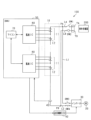
- the system 100 includes an assembled battery 10.
- the assembled battery 10 includes a series connection body of a plurality of battery modules 11 .
- Each battery module 11 comprises a series connection of a plurality of battery cells 12 .
- the number of battery cells 12 included in each battery module 11 is the same. However, the number of battery cells 12 included in each battery module 11 may be different.
- Each battery cell 12 is a rechargeable battery (secondary battery), specifically a lithium ion battery.
- the lithium ion storage battery of this embodiment is an LFP storage battery in which lithium iron phosphate is used as a positive electrode active material and graphite is used as a negative electrode active material.
- the rated voltage of each battery cell 12 constituting the battery module 11 is the same, and the rated capacity [Ah] of each battery cell 12 is the same.
- the system 100 includes a first charging path LA, a second charging path LB, a first external charging terminal TA, a second external charging terminal TB, a first switch SW1 and a second switch SW2.
- the first charging path LA connects the first external charging terminal TA and the positive terminal of the highest potential battery cell 12 constituting the assembled battery 10 .
- the second charging path LB connects the second external charging terminal TB to the negative terminal of the lowest potential battery cell 12 constituting the assembled battery 10 .
- a first switch SW1 is provided in the first charging path LA, and a second switch SW2 is provided in the second charging path LB.
- the assembled battery 10 is connected to the external charger 200 via the first and second external charging terminals TA, TB.
- External charger 200 is, for example, a DC quick charger.
- the external charger 200 is connected to the first and second external charging terminals TA and TB, the assembled battery 10 is charged with constant current or constant voltage by high-voltage DC power input from the external charger 200 .
- constant current charging is performed until just before the assembled battery 10 is fully charged, and then switching to constant voltage charging.
- the external charger 200 may be an AC charger instead of a DC charger.
- the system 100 includes a rotating electric machine 20, an inverter 30, a first electric path L1, a second electric path L2, a third switch SW3 and a fourth switch SW4.
- the first electrical path L1 connects a first connection point PA on the battery pack 10 side with respect to the first switch SW1 in the first charging path LA and the high potential side terminal of the inverter 30 .
- the second electrical path L2 connects a second connection point PB on the battery pack 10 side of the second charging path LB with respect to the second switch SW2 and the low potential side terminal of the inverter 30 .
- a third switch SW3 is provided on the first electrical path L1, and a fourth switch SW4 is provided on the second electrical path L2.
- the rotating electric machine 20 When the third switch SW3 and the fourth switch SW4 are turned on, the rotating electric machine 20 inputs and outputs electric power to and from the assembled battery 10 via the inverter 30 .
- the rotating electrical machine 20 applies propulsion force to the vehicle with electric power supplied from the assembled battery 10 during power running, and generates power using deceleration energy of the vehicle during regeneration, and supplies electric power to the assembled battery 10 .
- the system 100 includes a current sensor 40 and a BMU (Battery Management Unit) 50 as a battery monitoring device.
- the current sensor 40 detects current flowing through the assembled battery 10 .
- FIG. 1 shows that the current sensor 40 detects the current flowing through the second charging path LB.
- a value detected by the current sensor 40 is input to the BMU 50 .
- the BMU 50 turns on or off the first to fourth switches SW1 to SW4. Also, the BMU 50 is communicably connected to the traveling control ECU 42 via an in-vehicle network interface. The BMU 50 outputs a command for controlling the rotating electric machine 20 to the travel control ECU 42 based on the remaining capacity [Ah] of the assembled battery 10 . Based on a command from the BMU 50, the travel control ECU 42 performs switching control of the inverter 30 in order to control the control amount (for example, torque) of the rotary electric machine 20 to a command value.
- the control amount for example, torque
- the BMU 50 includes a monitoring IC 60 and a microcomputer 70 individually provided corresponding to each battery module 11 .
- the monitoring IC 60 detects the terminal voltage of each battery cell 12 forming the battery module 11 .
- Each monitoring IC 60 exchanges information with the microcomputer 70 .
- the microcomputer 70 acquires the terminal voltage detected by each monitoring IC 60 through an insulating element (not shown).
- the microcomputer 70 has a CPU.
- the functions provided by the microcomputer 70 can be provided by software recorded in a physical memory device, a computer executing the software, only software, only hardware, or a combination thereof.
- the microcomputer 70 executes a program stored in a non-transitory tangible storage medium as its own storage unit.
- the program includes, for example, a program for processing shown in FIG. 4 and the like. A method corresponding to the program is executed by executing the program.
- the storage unit is, for example, a non-volatile memory. Note that the program stored in the storage unit can be updated via a network such as the Internet, for example.
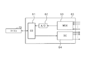
- the monitoring IC 60 includes a command section 61, an A/D converter 62, a switch section 63 and an equalization circuit section 64, as shown in FIG.
- the command section 61 has a function of interpreting commands from the microcomputer 70 .
- the switch section 63 has a function of arbitrarily selecting the voltage of each battery cell 12, and is, for example, a multiplexer.
- the A/D converter 62 converts the analog signal output from the switch section 63 into a digital signal.
- the converted digital signal is sent to the microcomputer 70 via the command section 61 .
- the microcomputer 70 acquires the terminal voltage of the battery cell 12 .
- the monitoring IC 60 performs processing according to commands from the microcomputer 70 by operating these units. For example, the monitoring IC 60 sequentially detects the terminal voltage of each battery cell 12 that constitutes the battery module 11 in a predetermined order.
- the equalization circuit unit 64 performs equalization processing for reducing voltage variations in each battery cell 12 that constitutes the battery module 11 based on a command from the microcomputer 70 .
- the equalization circuit section 64 is connected to each battery cell 12 .
- the equalization process is, for example, a process of discharging from the battery cell with the highest terminal voltage among the battery cells 12 . Note that, for example, when the microcomputer 70 determines that the difference between the highest voltage and the lowest voltage among the terminal voltage detection values of each battery cell 12 is equal to or greater than a predetermined voltage, the microcomputer 70 sends an equalization processing execution command to the monitoring IC 60. do it.
- a method for calculating the remaining capacity of the assembled battery 10 a method using SOC (State Of Charge) indicating the state of charge of the assembled battery 10 and the SOC-OCV characteristic indicating the correlation between the open circuit voltage (OCV) is known.
- SOC State Of Charge
- OCV open circuit voltage
- an LFP storage battery is used as the lithium ion storage battery.
- the OCV is stable over a wide range of remaining capacity, and has a plateau region SL where the change in OCV due to the change in capacity is small.
- the plateau region SL there are end regions SH where the change in OCV due to the change in capacitance is greater than that in the plateau region SL.
- a part of the plateau region SL is a specific region SB in which the change in OCV due to the change in capacitance is relatively large.
- the specific region SB is a region resulting from the negative electrode configuration of the battery cell 12 .
- the SOC of the battery cell 12 reaches a specific SOC or remaining capacity, the state of the battery cell 12 shifts to the specific region SB. Therefore, when the state of the battery cell 12 shifts to the specific area SB, it can be understood that the current SOC or remaining capacity of the battery cell 12 is the specific SOC or remaining capacity.
- the change in OCV is relatively large, the amount of change in OCV is small.
- the process shown in FIG. 4 is performed during charging of the assembled battery 10 by the charger 200 outside the vehicle, for example, in order to deal with this problem.
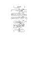
- FIG. 4 is a flowchart of SOC calculation processing of the battery cell 12 executed by the microcomputer 70.
- This process is repeatedly executed at a predetermined control cycle, for example, when it is determined that the state of the battery cell 12 is in the plateau region SL. Whether or not it is in the plateau region SL may be determined based on the terminal voltage of the battery cell acquired from the monitoring IC 60 .
- step S10 the terminal voltage of the first battery cell detected by the monitoring IC 60 (hereinafter referred to as first detection voltage V1d) and the terminal voltage of the second battery cell detected by the monitoring IC 60 (hereinafter referred to as second detection voltage V2d) and get.
- the first battery cell and the second battery cell are two battery cells selected from the battery cells 12 that constitute the battery module 11 . This selection method will be described in detail later.
- the process of step S10 corresponds to the "acquisition unit".
- step S11 the voltage difference ⁇ Vd (corresponding to "battery parameter") is calculated by subtracting the second detection voltage V2d from the first detection voltage V1d.
- step S12 it is determined whether or not the calculated voltage difference ⁇ Vd exceeds the determination value Vjde.
- step S12 If the determination in step S12 is affirmative, the process proceeds to step S13, and the SOCs of the first battery cell and the second battery cell are calculated as the specified value S ⁇ .
- the SOC of each battery cell 12 not limited to the first and second battery cells among the battery cells 12 constituting the battery module 11, may be calculated as the specified value S ⁇ , for example.
- the remaining capacities of the first and second battery cells may be calculated instead of the SOC.
- the processing of steps S11 to S13 corresponds to the "state calculation unit".
- FIG. 5(a) shows changes in the first and second detection voltages V1d and V2d
- FIG. 5(b) shows changes in the voltage difference ⁇ Vd
- FIG. 5(c) shows changes in the SOC of the first battery cell. show.
- the battery pack 10 is charged (constant current charging or constant voltage charging) by the external charger 200 .
- the state of the first battery cell shifts from the end region SH to the plateau region SL, and the rate of increase in terminal voltage associated with charging of the first battery cell slows down.
- the state of the second battery cell shifts from the end region SH to the plateau region SL, and the rate of increase in terminal voltage associated with charging of the second battery cell slows down. Since the first and second detection voltages V1d and V2d become equal after time t2, the voltage difference ⁇ Vd becomes a value close to zero.
- the SOCs of the first and second battery cells after time t1 are calculated by the microcomputer 70 based on, for example, the initial SOC based on the open-circuit voltage and the time integration value of the charging current flowing through the first and second battery cells. It is a calculated value.
- the microcomputer 70 determines that the voltage difference ⁇ Vd exceeds the determination value Vjde. Therefore, the microcomputer 70 calculates the SOC of the first and second battery cells as the specified value S ⁇ .
- the determination value Vjde is set to a value that allows it to be determined that the current control cycle is an intermediate timing between time t3 and time t6. Note that the SOCs of the first and second battery cells after time t4 are calculated by the microcomputer 70 based on, for example, the specified value S ⁇ and the time integrated value of the charging current flowing through the first and second battery cells. good.
- the state of the second battery cell shifts to the specific region SB, and the rising speed of the second detection voltage V2d temporarily increases from time t6 to t7. Since the first and second detection voltages V1d and V2d become equal after time t7, the voltage difference ⁇ Vd becomes a value close to zero. As a result, the rate of decrease in the voltage difference ⁇ Vd increases from time t6, and the voltage difference ⁇ Vd becomes a value close to 0 at time t7. Note that at time t8, the state of the first battery cell shifts to the end region SH.
- Noise is generated due to instantaneous changes in the current flowing through the battery pack 10 , and this noise can be superimposed on the terminal voltage detection value of each battery cell 12 .
- each battery cell 12 constituting the assembled battery 10 is connected in series. Therefore, it is considered that the effect of noise on the terminal voltage detection value of each battery cell 12 is the same. Therefore, the voltage difference ⁇ Vd, which is the difference between the terminal voltage detection values of the first and second battery cells, is a value with reduced influence of noise. Therefore, by using the voltage difference ⁇ Vd for estimating the SOC, it is possible to suppress deterioration in the calculation accuracy of the SOC even when noise occurs.
- an IC that can set the voltage detection range to either the entire voltage range that the battery cell 12 can take or a limited voltage range, which is a partial voltage range of the entire voltage range, may be used.
- the limited voltage range is selected as the voltage detection range, the voltage detection resolution is improved compared to when the full voltage range is selected as the voltage detection range.
- the limited voltage range is preferably set to, for example, the voltage range of the battery cells 12 included in the plateau region SL. In this case, the SOC calculation accuracy can be further improved.
- the microcomputer 70 sets the voltage detection range to the limited voltage range.
- the detected voltage is susceptible to noise.
- the microcomputer 70 may set the determination value Vjde larger as the variation in the SOC of each battery cell 12 at the start of charging of the assembled battery 10 increases. This setting is based on the fact that the peak value of the voltage difference ⁇ Vd increases as the variation in SOC increases.
- the microcomputer 70 may set the determination value Vjde larger as the temperatures of the first and second battery cells are higher or as the charging current detected by the current sensor 40 is smaller. This setting is based on the fact that the higher the temperature or the smaller the current, the larger the amount of increase in the detected voltage in the specific region SB.
- the selection unit 71 of the microcomputer 70 selects the battery cell with the highest terminal voltage detection value among the battery cells 12 as the first battery cell, and selects the battery cell with the lowest terminal voltage detection value. may be selected as the second battery cell. This is because, as shown in FIG. 7, the voltage difference ⁇ Vd in the specific region SB is increased to improve the calculation accuracy of the SOC.
- the selecting unit 71 may select the battery cell with the highest calculated SOC as the first battery cell from among the battery cells 12, and select the battery cell with the lowest calculated SOC as the second battery cell. .
- the selection unit 71 may select two battery cells connected in series and adjacent to each other among the battery cells 12 as the first battery cell and the second battery cell. Since the temperatures of two adjacent battery cells are close, it is possible to improve the accuracy of calculating the SOC based on the voltage difference ⁇ Vd.
- the first and second battery cells may be selected from all the battery cells 12 that make up the assembled battery 10, or may be selected from each of the battery cells 12 that make up each battery module 11. Alternatively, it may be selected from among the battery cells 12 to be monitored by the same monitoring IC 60 .
- the selection unit 71 may select the first and second battery cells from among the battery cells 12 to be AD-converted by the same A/D converter 62 . In this case, since the voltage detection error of the battery cell 12 to be AD-converted becomes a close value, the calculation accuracy of the SOC can be improved.
- the selection unit 71 may select two battery cells whose detection timing is close among the battery cells 12 forming the assembled battery 10 as the first and second battery cells. In this case, the noise that is superimposed on the terminal voltage detection values of the first and second battery cells has a similar value, so that the SOC calculation accuracy can be improved.
- the selection unit 71 may select the first and second battery cells from among the battery cells 12 forming the assembled battery 10, which are provided with temperature sensors (eg, thermistors). Further, the selection unit 71 may select, as the first and second battery cells, battery cells having a temperature equal to or less than a predetermined difference among the battery cells 12 forming the assembled battery 10 .
- temperature sensors eg, thermistors
- step S11 the voltage difference ⁇ Vd may be calculated by subtracting the first detection voltage V1d from the second detection voltage V2d.
- the processing in step S12 should be "
- FIG. 8 shows a flowchart of the SOC calculation process according to this embodiment. This process is repeatedly executed at a predetermined control cycle, for example, when the microcomputer 70 determines that the state of the battery cell 12 is in the plateau region SL.
- step S20 the first detection voltage V1d and the second detection voltage V2d are acquired.
- step S21 the voltage difference ⁇ Vd is calculated by subtracting the second detection voltage V2d from the first detection voltage V1d.
- step S22 it is determined whether or not the determination flag Fjde is 0.
- step S22 If it is determined in step S22 that the determination flag Fjde is 0, the process proceeds to step S23 to determine whether or not the calculated voltage difference ⁇ Vd exceeds the first determination value Vjde1. If a negative determination is made in step S23, the process proceeds to step S26.
- step S23 If the determination in step S23 is affirmative, the process proceeds to step S24, and the SOC of the first battery cell is calculated as the specified value S ⁇ . Note that in step S24, the remaining capacity of the first battery cell may be calculated instead of the SOC.
- step S24 After completing the process of step S24, the process proceeds to step S25 and sets the determination flag Fjde to 1. After that, the process proceeds to step S26.
- step S26 it is determined whether or not both the condition that the determination flag Fjde is 1 and the condition that the calculated voltage difference ⁇ Vd is less than the second determination value Vjde2 are satisfied.
- the second determination value Vjde2 is set to a value smaller than the first determination value Vjde1.
- the second determination value Vjde2 is not limited to this, and may be set to a value greater than the first determination value Vjde1 or the same value as the first determination value Vjde1.
- step S26 If the determination in step S26 is affirmative, the process proceeds to step S27, and the SOC of the second battery cell is calculated as the specified value S ⁇ . In step S27, the remaining capacity of the second battery cell may be calculated instead of the SOC.
- FIG. 9A and 9B correspond to FIGS. 5A and 5B.
- the battery pack 10 is charged (constant current charging or constant voltage charging) by the external charger 200 .
- the state of the first battery cell shifts from the end region SH to the plateau region SL
- the state of the second battery cell shifts from the end region SH to the plateau region SL. Since the first and second detection voltages V1d and V2d become equal after time t2, the voltage difference ⁇ Vd becomes a value close to zero.
- the state of the first battery cell shifts to the specific region SB, and the rising speed of the first detection voltage V1d temporarily increases from time t3 to t5.
- the state of the second battery cell is still within the plateau region SL. Therefore, after time t3, the voltage difference ⁇ Vd increases, and at time t4, the microcomputer 70 determines that the voltage difference ⁇ Vd has exceeded the first determination value Vjde1. Therefore, the microcomputer 70 calculates the SOC of the first battery cell as the prescribed value S ⁇ .
- the state of the second battery cell shifts to the specific region SB, and the rising speed of the second detection voltage V2d temporarily increases from time t6 to t8.
- the microcomputer 70 determines that the voltage difference ⁇ Vd has fallen below the second determination value Vjde2. Therefore, the microcomputer 70 calculates the SOC of the second battery cell as the specified value S ⁇ .
- the state of the first battery cell shifts to the end region SH.
- the SOCs of the first and second battery cells can be calculated individually.
- FIG. 10 shows a flowchart of the SOC calculation process according to this embodiment. This process is repeatedly executed at a predetermined control cycle, for example, when the microcomputer 70 determines that the state of the battery cell 12 is in the plateau region SL.
- step S30 the first detected voltage V1d(t) and the second detected voltage V2d(t) are obtained.
- step S31 the voltage difference ⁇ Vd( t) is calculated.
- step S32 the voltage difference ⁇ Vd(t ⁇ 1) calculated in the previous control cycle is subtracted from the voltage difference ⁇ Vd(t) calculated in the current control cycle to calculate the voltage time change amount ⁇ Ad.
- step S33 it is determined whether or not the voltage time change amount ⁇ Ad crosses 0.
- step S33 determines whether the determination in step S33 is affirmative. If the determination in step S33 is affirmative, the process proceeds to step S34 to calculate the SOC of the first battery cell and the second battery cell as the specified value S ⁇ . In step S34, the remaining capacity of the first and second battery cells may be calculated instead of the SOC.
- FIG. 11(a) and 11(b) correspond to FIGS. 5(a) and 5(b), and FIG. 11(c) shows the transition of the voltage time variation ⁇ Ad.
- the battery pack 10 is charged (constant current charging or constant voltage charging) by the external charger 200 .
- the state of the first battery cell shifts from the end region SH to the plateau region SL
- the state of the second battery cell shifts from the end region SH to the plateau region SL.
- the first and second detection voltages V1d and V2d become equal, so the voltage difference ⁇ Vd becomes a value close to 0, and the voltage time change amount ⁇ Ad becomes 0 or a positive value close to 0.
- the voltage time change amount ⁇ Ad becomes 0 or a positive value close to 0.
- the state of the second battery cell shifts to the specific region SB, and the rising speed of the second detection voltage V2d temporarily increases from time t5 to t6.
- the voltage time change amount ⁇ Ad greatly changes to the negative side.
- the microcomputer 70 determines that the voltage time change amount ⁇ Ad straddles zero. Therefore, the microcomputer 70 calculates the SOC of the first and second battery cells as the specified value S ⁇ .
- the microcomputer 70 calculates the SOCs of the first and second battery cells as the specified value S ⁇ at time t4 when the voltage time variation amount ⁇ Ad is greatly reduced to a value close to 0, for example. good.
- (A) ( ⁇ Vd(tm)- ⁇ Vd(tm-1))/ ⁇ Ca ⁇ Ca indicates the amount of change in capacity [Ah] of the battery cell during a specified period from time tm-1 to time tm.
- the prescribed period is, for example, one control period of the microcomputer 70 or a period longer than one control period.
- the specified period can also be set as a period required for the amount of capacitance change ⁇ Ca to reach a predetermined amount of capacitance change, for example.
- ⁇ Vd(tm-1) is a value obtained by subtracting the second detection voltage V2d obtained at time tm-1 from the first detection voltage V1d obtained at time tm-1.
- ⁇ Vd(tm) is a value obtained by subtracting the second detection voltage V2d obtained at time tm from the first detection voltage V1d obtained at time tm.
- (B) ( ⁇ Vd(tm)- ⁇ Vd(tm-1))/ ⁇ SOC ⁇ SOC indicates the amount of change in the SOC of the battery cell during a specified period from time tm ⁇ 1 to time tm.
- the prescribed period in this case can be set, for example, as a period required for the SOC change amount ⁇ SOC to reach a predetermined SOC change amount, as described above.
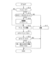
- FIG. 12 shows a flowchart of the processing for calculating the remaining capacity difference. This process is repeatedly executed at a predetermined control cycle, for example, when the microcomputer 70 determines that the state of the battery cell 12 is in the plateau region SL.
- step S40 the first detection voltage V1d and the second detection voltage V2d are acquired.
- step S41 the voltage difference ⁇ Vd is calculated by subtracting the second detection voltage V2d from the first detection voltage V1d.
- step S42 it is determined whether or not the determination flag Fjde is 0. If it is determined in step S42 that the determination flag Fjde is 0, the process proceeds to step S43 to determine whether or not the calculated voltage difference ⁇ Vd exceeds the first determination value Vjde1. If an affirmative determination is made in step S43, that is, if it is determined that the voltage difference ⁇ Vd changes in the positive direction and crosses over the first determination value Vjde1, the process proceeds to step S44, where the charging current time detected by the current sensor 40 is Start calculating the integrated value. After the processing of step S44 is completed, the process proceeds to step S45 and sets the determination flag Fjde to 1. After that, the process proceeds to step S46.
- step S46 it is determined whether or not both the first condition that the determination flag Fjde is 1 and the second condition that the calculated voltage difference ⁇ Vd is lower than the second determination value Vjde2 are satisfied.
- the second condition is a condition that the voltage difference ⁇ Vd changes in the negative direction and straddles the second determination value Vjde2.
- step S46 If an affirmative determination is made in step S46, the process proceeds to step S47, sets the determination flag Fjde to 0, and terminates the current integration process started in step S44.
- step S47 the time integrated value of the charging current calculated by the current integration process is calculated as the difference in remaining capacity between the first and second battery cells. Note that the difference in SOC between the first and second battery cells may be calculated based on the difference in remaining capacity.
- FIG. 13(c) shows the transition of the determination flag Fjde
- FIG. 13(d) shows the transition of the time integrated value of the charging current
- FIG. 13(e) shows the difference in remaining capacity between the first and second battery cells. shows the transition of the calculated value of
- the battery pack 10 is charged (constant current charging or constant voltage charging) by the external charger 200 .
- the state of the first battery cell shifts from the end region SH to the plateau region SL
- the state of the second battery cell shifts from the end region SH to the plateau region SL.
- the microcomputer 70 determines that the voltage difference ⁇ Vd has exceeded the first determination value Vjde1. Therefore, the determination flag Fjde is set to 1, and charging current integration processing is started.
- the microcomputer 70 determines that the voltage difference ⁇ Vd has fallen below the second determination value Vjde2. Therefore, the determination flag Fjde is set to 0, and the charging current integration process ends. Then, the value of the charging current accumulated from time t4 to t7 is calculated as the difference in remaining capacity between the first and second battery cells.
- the microcomputer 70 may determine that at least one of the first and second battery cells is out of order when determining that the calculated remaining capacity difference is equal to or greater than a predetermined capacity. Further, the microcomputer 70 may determine the discharge amount of the battery cell in the equalization process based on the calculated difference in remaining capacity.
- step S14 it is determined whether or not the charging start flag Fchr is 0.
- the charging start flag Fchr it indicates that the charging of the assembled battery 10 has not yet started, and when it is 1, it indicates that the charging has already started.
- the process proceeds to step S10.
- step S14 determines whether the charging start flag Fchr is 0, the process proceeds to step S15, and the SOC of the first battery cell (hereinafter referred to as SOC1) and the SOC of the second battery cell (hereinafter referred to as SOC2) are is greater than the threshold value Sth.
- SOC1 and SOC2 correspond to the "storage amount parameter".
- the stored electricity amount parameters are not limited to SOC1 and SOC2, and may be, for example, the first and second detection voltages V1d and V2d, or the remaining capacities of the first and second battery cells.
- step S15 the process proceeds to step S17, and discharge processing is performed to discharge from either the first or second battery cell.
- the second battery cell is discharged.
- the equalization circuit section 64 may be used for this discharge. This discharging continues until an affirmative determination is made in step S15.
- FIG. 15(a) shows transitions of SOC1 and SOC2
- FIG. 15(b) shows whether or not the discharge process of the second battery cell is executed.
- FIGS. 15(c) and (d) correspond to FIGS. 5(a) and (b).
- the microcomputer 70 determines that the absolute value of the difference between SOC1 and SOC2 is equal to or less than the threshold value Sth. Therefore, the discharge process is executed by the microcomputer 70 until time t2 when it is determined that this absolute value exceeds the threshold value Sth. After that, charging of the assembled battery 10 is started, and the SOC estimation process is executed. At time t3, microcomputer 70 determines that voltage difference ⁇ Vd has exceeded determination value Vjde, and calculates the SOC of the first battery cell as specified value S ⁇ .
- the voltage difference ⁇ Vd calculated in the SOC calculation process becomes small, and there is a concern that the accuracy of SOC calculation will decrease. Therefore, in the present embodiment, discharge processing is performed prior to SOC calculation processing. As a result, the SOC calculation process can be started with the difference between the SOC1 and the SOC2 increased, and a decrease in the accuracy of the SOC calculation can be avoided.
- the time to perform the discharge process for increasing the difference between SOC1 and SOC2 is not limited to before the battery pack 10 is charged.
- the microcomputer 70 calculates the absolute value of the difference between the SOC1 and the SOC2 each time during the charging of the assembled battery 10, and if it determines that the calculated absolute value is equal to or less than the threshold value Sth, while charging the assembled battery 10 You may perform the process of step S17.
- the threshold value Sth is set to the first threshold value Sth1, and the second threshold value Sth2 is set to a value larger than the first threshold value Sth1.
- the microcomputer 70 performs discharge processing over a period from when the absolute value of the difference between the SOC1 and SOC2 is determined to be equal to or less than the first threshold value Sth1 to when the absolute value is determined to be equal to or greater than the second threshold value Sth2. may be executed.
- one of the first and second battery cells is charged during the period from when the negative determination is made in step S15 to when the positive determination is made in step S15. You may change to the charge process which does.
- the difference in SOC between the first battery cell and the second battery cell may be increased by performing the discharging process on one of the first and second battery cells and the charging process on the other.
- the amount of reaction heat WR changes when the remaining capacity changes with energization.
- the reaction heat amount WR is obtained by subtracting the Joule heat WJ due to the impedance component of the storage battery from the heat generation amount WB of the storage battery due to energization.
- the amount of reaction heat WR is expressed by the following equation (2) using the temperature TM of the storage battery, the charging/discharging current IS, and the amount of voltage change ⁇ OCV, which is the amount of change in the open-circuit voltage OCV per unit temperature.
- the amount of reaction heat WR is proportional to the amount of voltage change ⁇ OCV.
- the amount of voltage change ⁇ OCV has a value for each capacity of the storage battery, and there are storage batteries in which the amount of voltage change ⁇ OCV changes when the capacity changes.
- the reaction heat amount WR changes, so the temperature TM changes.
- the temperature TM and the impedance have a correlation. Therefore, when the temperature TM of the storage battery changes, the impedance of the storage battery changes.
- FIG. 16 shows the relationship between the remaining capacity of the battery cell 12 of this embodiment and the voltage change amount ⁇ OCV.
- the battery cell 12 has a specific capacity region from a first capacity QA to a second capacity QB, and the specific capacity region is included in a plateau region SL.
- the voltage change amount ⁇ OCV rapidly increases, and when the remaining capacity crosses the second capacitor QB from the low capacity side, the voltage change amount ⁇ OCV sharply decreases.
- the first and second capacities QA and QB since the change in the voltage change amount ⁇ OCV is steep, the tendency of the impedance transition of the battery cell 12 during energization increases by crossing the first and second capacities QA and QB. Change.
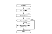
- FIG. 17 shows SOC calculation processing focused on this point. This process is repeatedly executed at a predetermined control cycle, for example, when the microcomputer 70 determines that the state of the battery cell 12 is in the plateau region SL.
- step S50 the impedance Z1 of the first battery cell and the impedance Z2 of the second battery cell are calculated.
- the amount of change ⁇ V1 in the first detection voltage V1d when the charging current flowing through the first battery cell changes during charging of the assembled battery 10 is divided by the amount of change ⁇ IS in the charging current. By doing so, the impedance Z1 of the first battery cell is calculated.
- step S51 the impedance difference ⁇ Z is calculated by subtracting the impedance Z1 of the first battery cell from the impedance Z2 of the second battery cell.
- the impedance difference ⁇ Z is a value with reduced influence of noise.
- step S52 it is determined whether or not the impedance difference ⁇ Z is below the determination value Zjde.
- step S53 the process proceeds to step S53 to calculate the SOC of the first battery cell and the second battery cell as the specified value S ⁇ .
- step S53 the remaining capacity of the first and second battery cells may be calculated instead of the SOC.
- FIG. 18(a) shows changes in the impedances Z1 and Z2 of the first and second battery cells
- FIG. 18(b) shows changes in the impedance difference ⁇ Z.
- the assembled battery 10 is charged by the external charger 200 .
- the impedance difference ⁇ Z is substantially constant until time t1.
- impedance difference ⁇ Z begins to decrease, and at time t2, microcomputer 70 determines that impedance difference ⁇ Z has fallen below determination value Zjde. Therefore, the microcomputer 70 calculates the SOC of the first and second battery cells as the specified value S ⁇ .
- the impedance of the second battery cell ceases to drop significantly, and the impedance difference ⁇ Z thereafter becomes substantially constant.
- the microcomputer 70 may calculate the SOC of the first battery cell as the specified value S ⁇ at time t1, and may calculate the SOC of the second battery cell as the specified value S ⁇ at time t2.
- the impedance difference ⁇ Z may be used instead of the voltage difference ⁇ Vd.
- the controller and techniques described in this disclosure can be performed by a dedicated computer provided by configuring a processor and memory programmed to perform one or more functions embodied by a computer program; may be implemented.
- the controls and techniques described in this disclosure may be implemented by a dedicated computer provided by configuring the processor with one or more dedicated hardware logic circuits.
- the control units and techniques described in this disclosure can be implemented by a combination of a processor and memory programmed to perform one or more functions and a processor configured by one or more hardware logic circuits. It may also be implemented by one or more dedicated computers configured.
- the computer program may also be stored as computer-executable instructions on a computer-readable non-transitional tangible recording medium.
Abstract
This battery monitoring device is to be applied to a battery pack (10) equipped with a plurality of battery cells (12) which are connected in series. The battery monitoring device is equipped with: an acquisition unit for acquiring a battery parameter, which is the terminal voltage or impedance of a first battery cell and a second battery cell among the battery cells during the charging or discharging of the battery cells; and a state calculation unit for calculating the difference between the acquired battery parameter of the first battery cell and the acquired battery parameter of the second battery cell, and calculating the battery state of the battery cell on the basis of the calculated difference.
Description
本出願は、2021年7月27日に出願された日本出願番号2021-122816号に基づくもので、ここにその記載内容を援用する。
This application is based on Japanese Application No. 2021-122816 filed on July 27, 2021, and the contents thereof are incorporated herein.
本開示は、電池監視装置、及びプログラムに関する。
The present disclosure relates to a battery monitoring device and a program.
リチウムイオン蓄電池等の蓄電池では、SOC(State Of Charge)の変化に伴う開放端電圧OCV(Open Circuit Voltage)の変化が小さい領域が存在する。この領域はプラトー領域と呼ばれる。プラトー領域では、SOCと開放端電圧OCVとの相関関係を示すSOC-OCV特性を用いて蓄電池のSOCを算出することが難しい。
In a storage battery such as a lithium ion storage battery, there is a region where the change in the open circuit voltage OCV (Open Circuit Voltage) due to the change in the SOC (State Of Charge) is small. This region is called the plateau region. In the plateau region, it is difficult to calculate the SOC of the storage battery using the SOC-OCV characteristic that indicates the correlation between the SOC and the open-circuit voltage OCV.
特許文献1には、プラトー領域のうち、一部の領域において蓄電池の容量変化に伴う電圧変化量が他の領域に対して相対的に大きく、上記他の領域において容量変化に伴う電圧変化量が略一定である電池特性があること、及び容量変化に伴う電圧変化量が大きくなる現象が特定のSOCで発生する電池特性があることが記載されている。特許文献1には、このような特性を利用して、蓄電池のSOCを推定する充電状態推定装置が記載されている。詳しくは、推定装置は、充電中又は放電中の蓄電池の状態がプラトー領域にある場合において、蓄電池の端子電圧検出値の時間変化率を算出する。推定装置は、算出した時間変化率が上に凸となる変曲点であると判定した場合、蓄電池の現在のSOCが、算出した時間変化率に予め紐づけられたSOCであると推定する。
In Patent Document 1, the amount of voltage change due to the capacity change of the storage battery is relatively large in some regions of the plateau region, and the voltage change amount due to the capacity change is relatively large in the other regions. It is described that there are battery characteristics that are substantially constant, and that there are battery characteristics in which a phenomenon in which the amount of voltage change accompanying a change in capacity increases occurs at a specific SOC. Patent Literature 1 describes a state-of-charge estimation device that estimates the SOC of a storage battery using such characteristics. Specifically, the estimating device calculates the time rate of change of the terminal voltage detection value of the storage battery when the state of the storage battery being charged or discharged is in the plateau region. The estimating device estimates that the current SOC of the storage battery is the SOC linked in advance to the calculated rate of change with time when it is determined that the calculated rate of change with time is an upwardly convex inflection point.
プラトー領域のうち、一部の領域において容量変化に伴う電圧変化量が相対的に大きいとはいえ、その電圧変化量の絶対値は小さい。このため、蓄電池の端子電圧検出値にノイズが重畳してしまうと、SOCの算出精度が大きく低下してしまう懸念がある。
Although the amount of voltage change accompanying the change in capacitance is relatively large in some areas of the plateau region, the absolute value of the amount of voltage change is small. Therefore, if noise is superimposed on the terminal voltage detection value of the storage battery, there is a concern that the calculation accuracy of the SOC may be greatly reduced.
なお、蓄電池のSOCに限らず、蓄電池の残容量等、蓄電池の電池状態を算出する場合において、ノイズに起因して電池状態の算出精度が大きく低下する懸念がある。
Note that when calculating the battery state of the storage battery, such as the remaining capacity of the storage battery, not only the SOC of the storage battery, there is a concern that the calculation accuracy of the battery state may be greatly reduced due to noise.
本開示は、電池状態の算出精度の低下を抑制できる電機監視装置及びプログラムを提供することを主たる目的とする。
The main purpose of the present disclosure is to provide an electric machine monitoring device and a program that can suppress deterioration in the accuracy of battery state calculation.
本開示は、直列接続される複数の電池セルを備える組電池に適用され、
前記各電池セルの充電中又は放電中において、前記各電池セルのうち第1電池セル及び第2電池セルの端子電圧又はインピーダンスのいずれかである電池パラメータを取得する取得部と、
取得した前記第1電池セルの前記電池パラメータと、取得した前記第2電池セルの前記電池パラメータとの差を算出し、算出した前記差に基づいて、前記電池セルの電池状態を算出する状態算出部と、を備える。 The present disclosure is applied to an assembled battery including a plurality of battery cells connected in series,
an acquisition unit that acquires a battery parameter that is either terminal voltage or impedance of a first battery cell and a second battery cell among the battery cells during charging or discharging of the battery cells;
State calculation for calculating a difference between the obtained battery parameter of the first battery cell and the obtained battery parameter of the second battery cell, and calculating the battery state of the battery cell based on the calculated difference and
組電池を構成する複数の電池セルは、直列接続される。このため、端子電圧又はインピーダンスのいずれかを電池パラメータとする場合、各電池セルの電池パラメータに対するノイズの影響は同程度であると考えられる。このため、組電池を構成する各電池セルのうち2つの電池セルの電池パラメータの差は、ノイズの影響が低減された値となる。
A plurality of battery cells that make up an assembled battery are connected in series. Therefore, when either the terminal voltage or the impedance is used as the battery parameter, it is considered that the effect of noise on the battery parameter of each battery cell is the same. Therefore, the difference between the battery parameters of two battery cells among the battery cells constituting the assembled battery is a value with reduced influence of noise.
この点に鑑み、本開示の状態算出部は、取得した第1電池セルの電池パラメータと、取得した第2電池セルの電池パラメータとの差を算出し、算出した差に基づいて、電池セルの電池状態を算出する。これにより、電池状態の算出精度の低下を抑制することができる。
In view of this point, the state calculation unit of the present disclosure calculates the difference between the acquired battery parameter of the first battery cell and the acquired battery parameter of the second battery cell, and based on the calculated difference, Calculate battery status. As a result, it is possible to suppress a decrease in accuracy in calculating the battery state.
本開示についての上記目的およびその他の目的、特徴や利点は、添付の図面を参照しながら下記の詳細な記述により、より明確になる。その図面は、
図1は、第1実施形態に係るシステムの全体構成図であり、
図2は、監視ICの構成を示す図であり、
図3は、電池セルの電圧及び容量の関係を示す図であり、
図4は、SOC算出処理の手順を示すフローチャートであり、
図5は、充電中の電池セルの端子電圧、電圧差及びSOCの推移を示すタイムチャートであり、
図6は、第1実施形態の変形例に係るマイコンの選択部を示す図であり、
図7は、端子電圧が最高,最低の電池セルの端子電圧の推移を示すタイムチャートであり、
図8は、第2実施形態に係るSOC算出処理の手順を示すフローチャートであり、
図9は、充電中の電池セルの端子電圧及び電圧差の推移を示すタイムチャートであり、
図10は、第3実施形態に係るSOC算出処理の手順を示すフローチャートであり、
図11は、充電中の電池セルの端子電圧、電圧差及び電圧時間変化量の推移を示すタイムチャートであり、
図12は、第4実施形態に係る容量差算出処理の手順を示すフローチャートであり、
図13は、充電中の電池セルの端子電圧、電圧差及び電流積算値等の推移を示すタイムチャートであり、
図14は、第5実施形態に係るSOC算出処理の手順を示すフローチャートであり、
図15は、電池セルのSOC及び端子電圧等の推移を示すタイムチャートであり、
図16は、第6実施形態に係る電池セルの残容量及び電圧変化量の関係を示す図であり、
図17は、SOC算出処理の手順を示すフローチャートであり、
図18は、電池セルのインピーダンス及びインピーダンス差の推移を示すタイムチャートである。
The above and other objects, features and advantages of the present disclosure will become more apparent from the following detailed description with reference to the accompanying drawings. The drawing is
FIG. 1 is an overall configuration diagram of the system according to the first embodiment, FIG. 2 is a diagram showing the configuration of the monitoring IC; FIG. 3 is a diagram showing the relationship between the voltage and capacity of the battery cell, FIG. 4 is a flowchart showing the procedure of the SOC calculation process; FIG. 5 is a time chart showing changes in the terminal voltage, voltage difference, and SOC of the battery cell during charging, FIG. 6 is a diagram showing a selection unit of a microcomputer according to a modification of the first embodiment; FIG. 7 is a time chart showing changes in terminal voltages of battery cells with the highest and lowest terminal voltages; FIG. 8 is a flowchart showing the procedure of SOC calculation processing according to the second embodiment; FIG. 9 is a time chart showing changes in terminal voltage and voltage difference of battery cells during charging, FIG. 10 is a flowchart showing the procedure of SOC calculation processing according to the third embodiment; FIG. 11 is a time chart showing changes in terminal voltage, voltage difference, and voltage time change of a battery cell during charging; FIG. 12 is a flowchart showing the procedure of capacitance difference calculation processing according to the fourth embodiment. FIG. 13 is a time chart showing changes in the terminal voltage, voltage difference, current integrated value, etc. of the battery cell during charging; FIG. 14 is a flowchart showing the procedure of SOC calculation processing according to the fifth embodiment; FIG. 15 is a time chart showing the transition of the SOC and terminal voltage of the battery cell, FIG. 16 is a diagram showing the relationship between the remaining capacity and voltage change amount of the battery cell according to the sixth embodiment, FIG. 17 is a flowchart showing the procedure of the SOC calculation process; FIG. 18 is a time chart showing changes in the impedance of the battery cell and the impedance difference.
<第1実施形態>
以下、本開示に係る電池監視装置を具体化した第1実施形態について、図面を参照しつつ説明する。本実施形態の電池監視装置を含むシステムは、ハイブリッド自動車、電気自動車及び燃料電池車等の車両に搭載される。車両には、乗用車、バス、建設作業車及び農業機械車両が含まれる。ただし、システムは、車両に搭載されるシステムに限らず、例えば定置式のシステムであってもよい。 <First embodiment>
A first embodiment embodying a battery monitoring device according to the present disclosure will be described below with reference to the drawings. A system including the battery monitoring device of this embodiment is mounted on a vehicle such as a hybrid vehicle, an electric vehicle, or a fuel cell vehicle. Vehicles include passenger cars, buses, construction vehicles and agricultural machinery vehicles. However, the system is not limited to a system mounted on a vehicle, and may be a stationary system, for example.
図1に示すように、システム100は、組電池10を備えている。組電池10は、複数の電池モジュール11の直列接続体を備えている。各電池モジュール11は、複数の電池セル12の直列接続体を備えている。本実施形態において、各電池モジュール11が備える電池セル12の数は同じである。ただし、各電池モジュール11が備える電池セル12の数は異なっていてもよい。
As shown in FIG. 1, the system 100 includes an assembled battery 10. The assembled battery 10 includes a series connection body of a plurality of battery modules 11 . Each battery module 11 comprises a series connection of a plurality of battery cells 12 . In this embodiment, the number of battery cells 12 included in each battery module 11 is the same. However, the number of battery cells 12 included in each battery module 11 may be different.
各電池セル12は、充放電可能な蓄電池(2次電池)であり、具体的には、リチウムイオン蓄電池である。本実施形態のリチウムイオン蓄電池は、正極活物質にリン酸鉄リチウムが使用され、負極活物質に黒鉛が使用されたLFP蓄電池である。電池モジュール11を構成する各電池セル12の定格電圧は同じであり、各電池セル12の定格容量[Ah]は同じである。
Each battery cell 12 is a rechargeable battery (secondary battery), specifically a lithium ion battery. The lithium ion storage battery of this embodiment is an LFP storage battery in which lithium iron phosphate is used as a positive electrode active material and graphite is used as a negative electrode active material. The rated voltage of each battery cell 12 constituting the battery module 11 is the same, and the rated capacity [Ah] of each battery cell 12 is the same.
システム100は、第1充電経路LA、第2充電経路LB、第1外部充電端子TA、第2外部充電端子TB、第1スイッチSW1及び第2スイッチSW2を備えている。第1充電経路LAは、第1外部充電端子TAと、組電池10を構成する各電池セル12のうち最高電位側の電池セルの正極端子とを接続する。第2充電経路LBは、第2外部充電端子TBと、組電池10を構成する各電池セル12のうち最低電位側の電池セルの負極端子とを接続する。第1充電経路LAには第1スイッチSW1が設けられ、第2充電経路LBには第2スイッチSW2が設けられている。
The system 100 includes a first charging path LA, a second charging path LB, a first external charging terminal TA, a second external charging terminal TB, a first switch SW1 and a second switch SW2. The first charging path LA connects the first external charging terminal TA and the positive terminal of the highest potential battery cell 12 constituting the assembled battery 10 . The second charging path LB connects the second external charging terminal TB to the negative terminal of the lowest potential battery cell 12 constituting the assembled battery 10 . A first switch SW1 is provided in the first charging path LA, and a second switch SW2 is provided in the second charging path LB.
第1スイッチSW1及び第2スイッチSW2がオンされると、組電池10は、第1,第2外部充電端子TA,TBを介して車外充電器200に接続される。車外充電器200は、例えばDC急速充電器である。組電池10は、第1,第2外部充電端子TA,TBに車外充電器200が接続されると、車外充電器200から入力される高圧の直流電力により定電流充電又は定電圧充電される。例えば、組電池10が満充電になる直前まで定電流充電され、その後定電圧充電に切り替えられる。なお、車外充電器200は、DCではなく、AC充電器であってもよい。
When the first switch SW1 and the second switch SW2 are turned on, the assembled battery 10 is connected to the external charger 200 via the first and second external charging terminals TA, TB. External charger 200 is, for example, a DC quick charger. When the external charger 200 is connected to the first and second external charging terminals TA and TB, the assembled battery 10 is charged with constant current or constant voltage by high-voltage DC power input from the external charger 200 . For example, constant current charging is performed until just before the assembled battery 10 is fully charged, and then switching to constant voltage charging. Note that the external charger 200 may be an AC charger instead of a DC charger.
システム100は、回転電機20、インバータ30、第1電気経路L1、第2電気経路L2、第3スイッチSW3及び第4スイッチSW4を備えている。第1電気経路L1は、第1充電経路LAのうち第1スイッチSW1よりも組電池10側の第1接続点PAと、インバータ30の高電位側端子とを接続する。第2電気経路L2は、第2充電経路LBのうち第2スイッチSW2よりも組電池10側の第2接続点PBと、インバータ30の低電位側端子とを接続する。第1電気経路L1には第3スイッチSW3が設けられ、第2電気経路L2には第4スイッチSW4が設けられている。
The system 100 includes a rotating electric machine 20, an inverter 30, a first electric path L1, a second electric path L2, a third switch SW3 and a fourth switch SW4. The first electrical path L1 connects a first connection point PA on the battery pack 10 side with respect to the first switch SW1 in the first charging path LA and the high potential side terminal of the inverter 30 . The second electrical path L2 connects a second connection point PB on the battery pack 10 side of the second charging path LB with respect to the second switch SW2 and the low potential side terminal of the inverter 30 . A third switch SW3 is provided on the first electrical path L1, and a fourth switch SW4 is provided on the second electrical path L2.
第3スイッチSW3及び第4スイッチSW4がオンされると、回転電機20は、インバータ30を介して組電池10との間で電力の入出力を行う。回転電機20は、力行時において、組電池10から供給される電力により車両に推進力を付与し、回生時において、車両の減速エネルギを用いて発電を行い、組電池10に電力を供給する。
When the third switch SW3 and the fourth switch SW4 are turned on, the rotating electric machine 20 inputs and outputs electric power to and from the assembled battery 10 via the inverter 30 . The rotating electrical machine 20 applies propulsion force to the vehicle with electric power supplied from the assembled battery 10 during power running, and generates power using deceleration energy of the vehicle during regeneration, and supplies electric power to the assembled battery 10 .
システム100は、電流センサ40と、電池監視装置としてのBMU(Battery Management Unit)50とを備えている。電流センサ40は、組電池10に流れる電流を検出する。図1には、電流センサ40が第2充電経路LBに流れる電流を検出することが示されている。電流センサ40の検出値は、BMU50に入力される。
The system 100 includes a current sensor 40 and a BMU (Battery Management Unit) 50 as a battery monitoring device. The current sensor 40 detects current flowing through the assembled battery 10 . FIG. 1 shows that the current sensor 40 detects the current flowing through the second charging path LB. A value detected by the current sensor 40 is input to the BMU 50 .
なお、BMU50は、第1~第4スイッチSW1~SW4をオン又はオフする。また、BMU50は、車載ネットワークインタフェースを介して、走行制御ECU42と通信可能に接続されている。BMU50は、組電池10の残容量[Ah]に基づいて、回転電機20を制御する指令を走行制御ECU42に出力する。走行制御ECU42は、BMU50からの指令に基づいて、回転電機20の制御量(例えばトルク)を指令値に制御すべく、インバータ30のスイッチング制御を行う。
The BMU 50 turns on or off the first to fourth switches SW1 to SW4. Also, the BMU 50 is communicably connected to the traveling control ECU 42 via an in-vehicle network interface. The BMU 50 outputs a command for controlling the rotating electric machine 20 to the travel control ECU 42 based on the remaining capacity [Ah] of the assembled battery 10 . Based on a command from the BMU 50, the travel control ECU 42 performs switching control of the inverter 30 in order to control the control amount (for example, torque) of the rotary electric machine 20 to a command value.
BMU50は、各電池モジュール11に対応して個別に設けられた監視IC60と、マイコン70とを備えている。監視IC60は、電池モジュール11を構成する各電池セル12の端子電圧を検出する。各監視IC60は、マイコン70と情報のやり取りを行う。マイコン70は、各監視IC60により検出された端子電圧を、図示しない絶縁素子を介して取得する。
The BMU 50 includes a monitoring IC 60 and a microcomputer 70 individually provided corresponding to each battery module 11 . The monitoring IC 60 detects the terminal voltage of each battery cell 12 forming the battery module 11 . Each monitoring IC 60 exchanges information with the microcomputer 70 . The microcomputer 70 acquires the terminal voltage detected by each monitoring IC 60 through an insulating element (not shown).
マイコン70は、CPUを備えている。マイコン70が提供する機能は、実体的なメモリ装置に記録されたソフトウェアおよびそれを実行するコンピュータ、ソフトウェアのみ、ハードウェアのみ、あるいはそれらの組合せによって提供することができる。例えば、マイコン70がハードウェアである電子回路によって提供される場合、それは多数の論理回路を含むデジタル回路、又はアナログ回路によって提供することができる。例えば、マイコン70は、自身が備える記憶部としての非遷移的実体的記録媒体(non-transitory tangible storage medium)に格納されたプログラムを実行する。プログラムには、例えば、図4等に示す処理のプログラムが含まれる。プログラムが実行されることにより、プログラムに対応する方法が実行される。記憶部は、例えば不揮発性メモリである。なお、記憶部に記憶されたプログラムは、例えば、インターネット等のネットワークを介して更新可能である。
The microcomputer 70 has a CPU. The functions provided by the microcomputer 70 can be provided by software recorded in a physical memory device, a computer executing the software, only software, only hardware, or a combination thereof. For example, if the microcomputer 70 is provided by an electronic circuit that is hardware, it can be provided by a digital circuit including a number of logic circuits, or an analog circuit. For example, the microcomputer 70 executes a program stored in a non-transitory tangible storage medium as its own storage unit. The program includes, for example, a program for processing shown in FIG. 4 and the like. A method corresponding to the program is executed by executing the program. The storage unit is, for example, a non-volatile memory. Note that the program stored in the storage unit can be updated via a network such as the Internet, for example.
監視IC60は、図2に示すように、コマンド部61、A/Dコンバータ62、スイッチ部63及び均等化回路部64を備えている。コマンド部61は、マイコン70からのコマンドを解釈する機能を有する。スイッチ部63は、各電池セル12の電圧を任意に選択できる機能を有し、例えばマルチプレクサである。A/Dコンバータ62は、スイッチ部63から出力されたアナログ信号をデジタル信号に変換する。変換されたデジタル信号は、コマンド部61を介してマイコン70に送信される。これにより、マイコン70は、電池セル12の端子電圧を取得する。監視IC60は、これら各部の作動により、マイコン70からのコマンドに応じた処理を行う。例えば、監視IC60は、電池モジュール11を構成する各電池セル12の端子電圧を所定の順序で順次検出する。
The monitoring IC 60 includes a command section 61, an A/D converter 62, a switch section 63 and an equalization circuit section 64, as shown in FIG. The command section 61 has a function of interpreting commands from the microcomputer 70 . The switch section 63 has a function of arbitrarily selecting the voltage of each battery cell 12, and is, for example, a multiplexer. The A/D converter 62 converts the analog signal output from the switch section 63 into a digital signal. The converted digital signal is sent to the microcomputer 70 via the command section 61 . Thereby, the microcomputer 70 acquires the terminal voltage of the battery cell 12 . The monitoring IC 60 performs processing according to commands from the microcomputer 70 by operating these units. For example, the monitoring IC 60 sequentially detects the terminal voltage of each battery cell 12 that constitutes the battery module 11 in a predetermined order.
均等化回路部64は、マイコン70からの指令に基づいて、電池モジュール11を構成する各電池セル12における電圧ばらつきを低減するための均等化処理を行う。均等化回路部64は、各電池セル12に接続されている。均等化処理は、例えば、各電池セル12のうち、端子電圧が最も高い電池セルからの放電を実施する処理である。なお、マイコン70は、例えば、各電池セル12の端子電圧検出値のうち、最高電圧と最低電圧との差が所定電圧以上であると判定した場合、監視IC60に均等化処理の実行指令を送信すればよい。
The equalization circuit unit 64 performs equalization processing for reducing voltage variations in each battery cell 12 that constitutes the battery module 11 based on a command from the microcomputer 70 . The equalization circuit section 64 is connected to each battery cell 12 . The equalization process is, for example, a process of discharging from the battery cell with the highest terminal voltage among the battery cells 12 . Note that, for example, when the microcomputer 70 determines that the difference between the highest voltage and the lowest voltage among the terminal voltage detection values of each battery cell 12 is equal to or greater than a predetermined voltage, the microcomputer 70 sends an equalization processing execution command to the monitoring IC 60. do it.
ところで、組電池10の残容量を算出する方法として、組電池10の蓄電状態を示すSOC(State Of Charge)と開放端電圧(OCV)との相関関係を示すSOC-OCV特性を用いる方法が知られている。しかし、本実施形態では、リチウムイオン蓄電池としてLFP蓄電池が用いられている。LFP蓄電池では、図3に示すように、残容量の広い範囲でOCVが安定しており、容量の変化に伴うOCVの変化が小さいプラトー領域SLを有している。プラトー領域SLの両端には、容量の変化に伴うOCVの変化がプラトー領域SLよりも大きい端部領域SHが存在する。プラトー領域SLでは、SOC-OCV特性を用いて蓄電池のSOCを算出し、残容量を算出することが難しい。
By the way, as a method for calculating the remaining capacity of the assembled battery 10, a method using SOC (State Of Charge) indicating the state of charge of the assembled battery 10 and the SOC-OCV characteristic indicating the correlation between the open circuit voltage (OCV) is known. It is However, in this embodiment, an LFP storage battery is used as the lithium ion storage battery. In the LFP storage battery, as shown in FIG. 3, the OCV is stable over a wide range of remaining capacity, and has a plateau region SL where the change in OCV due to the change in capacity is small. At both ends of the plateau region SL, there are end regions SH where the change in OCV due to the change in capacitance is greater than that in the plateau region SL. In the plateau region SL, it is difficult to calculate the SOC of the storage battery using the SOC-OCV characteristic and calculate the remaining capacity.
プラトー領域SLのうち一部の領域は、容量変化に伴うOCVの変化が相対的に大きい特定領域SBである。特定領域SBは、電池セル12の負極構成に起因する領域である。電池セル12のSOCが特定のSOC又は残容量になる場合、電池セル12の状態が特定領域SBに移行する。このため、電池セル12の状態が特定領域SBに移行したことをもって、電池セル12の現在のSOC又は残容量が、特定のSOC又は残容量であることを把握できる。ただし、OCVの変化が相対的に大きいとはいえ、OCVの変化量は小さい。このため、電池セル12の端子電圧検出値にノイズが重畳してしまうと、SOCの算出精度が大きく低下してしまう懸念がある。本実施形態では、この問題に対処すべく、例えば車外充電器200による組電池10の充電中において、図4に示す処理が実行される。
A part of the plateau region SL is a specific region SB in which the change in OCV due to the change in capacitance is relatively large. The specific region SB is a region resulting from the negative electrode configuration of the battery cell 12 . When the SOC of the battery cell 12 reaches a specific SOC or remaining capacity, the state of the battery cell 12 shifts to the specific region SB. Therefore, when the state of the battery cell 12 shifts to the specific area SB, it can be understood that the current SOC or remaining capacity of the battery cell 12 is the specific SOC or remaining capacity. However, although the change in OCV is relatively large, the amount of change in OCV is small. Therefore, if noise is superimposed on the terminal voltage detection value of the battery cell 12, there is a concern that the calculation accuracy of the SOC may be greatly reduced. In the present embodiment, the process shown in FIG. 4 is performed during charging of the assembled battery 10 by the charger 200 outside the vehicle, for example, in order to deal with this problem.
図4は、マイコン70により実行される電池セル12のSOC算出処理のフローチャートである。この処理は、例えば、電池セル12の状態がプラトー領域SLであると判定された場合、所定の制御周期で繰り返し実行される。プラトー領域SLであるか否かは、監視IC60から取得した電池セルの端子電圧に基づいて判定されればよい。
FIG. 4 is a flowchart of SOC calculation processing of the battery cell 12 executed by the microcomputer 70. FIG. This process is repeatedly executed at a predetermined control cycle, for example, when it is determined that the state of the battery cell 12 is in the plateau region SL. Whether or not it is in the plateau region SL may be determined based on the terminal voltage of the battery cell acquired from the monitoring IC 60 .
ステップS10では、監視IC60により検出された第1電池セルの端子電圧(以下、第1検出電圧V1d)と、監視IC60により検出された第2電池セルの端子電圧(以下、第2検出電圧V2d)とを取得する。第1電池セル及び第2電池セルは、電池モジュール11を構成する各電池セル12の中から選択した2つの電池セルである。この選択方法については、後に詳述する。ステップS10の処理が「取得部」に相当する。
In step S10, the terminal voltage of the first battery cell detected by the monitoring IC 60 (hereinafter referred to as first detection voltage V1d) and the terminal voltage of the second battery cell detected by the monitoring IC 60 (hereinafter referred to as second detection voltage V2d) and get. The first battery cell and the second battery cell are two battery cells selected from the battery cells 12 that constitute the battery module 11 . This selection method will be described in detail later. The process of step S10 corresponds to the "acquisition unit".
ステップS11では、第1検出電圧V1dから第2検出電圧V2dを差し引くことにより、電圧差ΔVd(「電池パラメータ」に相当)を算出する。
In step S11, the voltage difference ΔVd (corresponding to "battery parameter") is calculated by subtracting the second detection voltage V2d from the first detection voltage V1d.
ステップS12では、算出した電圧差ΔVdが判定値Vjdeを超えているか否かを判定する。
In step S12, it is determined whether or not the calculated voltage difference ΔVd exceeds the determination value Vjde.
ステップS12において肯定判定した場合には、ステップS13に進み、第1電池セル及び第2電池セルのSOCを規定値Sαとして算出する。なお、電池モジュール11を構成する各電池セル12のうち第1,第2電池セルに限らず、例えば、各電池セル12のSOCを規定値Sαとして算出してもよい。また、ステップS13において、SOCに代えて、第1,第2電池セルの残容量を算出してもよい。ステップS11~S13の処理が「状態算出部」に相当する。
If the determination in step S12 is affirmative, the process proceeds to step S13, and the SOCs of the first battery cell and the second battery cell are calculated as the specified value Sα. Note that the SOC of each battery cell 12, not limited to the first and second battery cells among the battery cells 12 constituting the battery module 11, may be calculated as the specified value Sα, for example. Also, in step S13, the remaining capacities of the first and second battery cells may be calculated instead of the SOC. The processing of steps S11 to S13 corresponds to the "state calculation unit".
図5を用いて、SOC算出処理について説明する。図5(a)は第1,第2検出電圧V1d,V2dの推移を示し、図5(b)は電圧差ΔVdの推移を示し、図5(c)は第1電池セルのSOCの推移を示す。図5に示す例では、車外充電器200により組電池10が充電(定電流充電又は定電圧充電)されている。
The SOC calculation process will be explained using FIG. 5(a) shows changes in the first and second detection voltages V1d and V2d, FIG. 5(b) shows changes in the voltage difference ΔVd, and FIG. 5(c) shows changes in the SOC of the first battery cell. show. In the example shown in FIG. 5 , the battery pack 10 is charged (constant current charging or constant voltage charging) by the external charger 200 .
時刻t1において、第1電池セルの状態が端部領域SHからプラトー領域SLに移行し、第1電池セルの充電に伴う端子電圧の上昇速度が低下する。時刻t2において、第2電池セルの状態が端部領域SHからプラトー領域SLに移行し、第2電池セルの充電に伴う端子電圧の上昇速度が低下する。時刻t2以降において、第1,第2検出電圧V1d,V2dが同等になるため、電圧差ΔVdが0に近い値となる。なお、時刻t1以降の第1,第2電池セルのSOCは、例えば、開放端電圧に基づく初期SOCと、第1,第2電池セルに流れる充電電流の時間積算値とに基づいてマイコン70により算出された値である。
At time t1, the state of the first battery cell shifts from the end region SH to the plateau region SL, and the rate of increase in terminal voltage associated with charging of the first battery cell slows down. At time t2, the state of the second battery cell shifts from the end region SH to the plateau region SL, and the rate of increase in terminal voltage associated with charging of the second battery cell slows down. Since the first and second detection voltages V1d and V2d become equal after time t2, the voltage difference ΔVd becomes a value close to zero. Note that the SOCs of the first and second battery cells after time t1 are calculated by the microcomputer 70 based on, for example, the initial SOC based on the open-circuit voltage and the time integration value of the charging current flowing through the first and second battery cells. It is a calculated value.
その後、時刻t3において、第1電池セルの状態が特定領域SBに移行し、時刻t3~t5において第1検出電圧V1dの上昇速度が一時的に高くなる。一方、第2電池セルの状態は未だプラトー領域SL内である。このため、時刻t3以降において、電圧差ΔVdが上昇し、時刻t4において、電圧差ΔVdが判定値Vjdeを超えたとマイコン70により判定される。このため、マイコン70は、第1,第2電池セルのSOCを規定値Sαとして算出する。判定値Vjdeは、現在の制御周期が、時刻t3と時刻t6との中間タイミングであることを判定できる値に設定されている。なお、時刻t4以降の第1,第2電池セルのSOCは、例えば、規定値Sαと、第1,第2電池セルに流れる充電電流の時間積算値とに基づいてマイコン70により算出されればよい。
After that, at time t3, the state of the first battery cell shifts to the specific region SB, and the rising speed of the first detection voltage V1d temporarily increases from time t3 to t5. On the other hand, the state of the second battery cell is still within the plateau region SL. Therefore, after time t3, the voltage difference ΔVd increases, and at time t4, the microcomputer 70 determines that the voltage difference ΔVd exceeds the determination value Vjde. Therefore, the microcomputer 70 calculates the SOC of the first and second battery cells as the specified value Sα. The determination value Vjde is set to a value that allows it to be determined that the current control cycle is an intermediate timing between time t3 and time t6. Note that the SOCs of the first and second battery cells after time t4 are calculated by the microcomputer 70 based on, for example, the specified value Sα and the time integrated value of the charging current flowing through the first and second battery cells. good.
時刻t6において、第2電池セルの状態が特定領域SBに移行し、時刻t6~t7において第2検出電圧V2dの上昇速度が一時的に高くなる。時刻t7以降において、第1,第2検出電圧V1d,V2dが同等になるため、電圧差ΔVdが0に近い値となる。その結果、時刻t6から電圧差ΔVdの低下速度が大きくなり、時刻t7において、電圧差ΔVdが0に近い値となる。なお、時刻t8において、第1電池セルの状態が端部領域SHに移行する。
At time t6, the state of the second battery cell shifts to the specific region SB, and the rising speed of the second detection voltage V2d temporarily increases from time t6 to t7. Since the first and second detection voltages V1d and V2d become equal after time t7, the voltage difference ΔVd becomes a value close to zero. As a result, the rate of decrease in the voltage difference ΔVd increases from time t6, and the voltage difference ΔVd becomes a value close to 0 at time t7. Note that at time t8, the state of the first battery cell shifts to the end region SH.
以上詳述した本実施形態によれば、以下の効果が得られるようになる。
According to this embodiment detailed above, the following effects can be obtained.
組電池10に流れる電流の瞬間的な変化によりノイズが発生し、このノイズは、各電池セル12の端子電圧検出値に重畳し得る。ここで、組電池10を構成する各電池セル12は、直列接続されている。このため、各電池セル12の端子電圧検出値に対するノイズの影響は同程度であると考えられる。したがって、第1,第2電池セルの端子電圧検出値の差である電圧差ΔVdは、ノイズの影響が低減された値である。このため、SOCの推定に電圧差ΔVdが用いられることにより、ノイズが発生する場合であっても、SOCの算出精度の低下を抑制することができる。
Noise is generated due to instantaneous changes in the current flowing through the battery pack 10 , and this noise can be superimposed on the terminal voltage detection value of each battery cell 12 . Here, each battery cell 12 constituting the assembled battery 10 is connected in series. Therefore, it is considered that the effect of noise on the terminal voltage detection value of each battery cell 12 is the same. Therefore, the voltage difference ΔVd, which is the difference between the terminal voltage detection values of the first and second battery cells, is a value with reduced influence of noise. Therefore, by using the voltage difference ΔVd for estimating the SOC, it is possible to suppress deterioration in the calculation accuracy of the SOC even when noise occurs.
監視IC60として、電池セル12が取り得る全電圧範囲、又は全電圧範囲のうち一部の電圧範囲である限定電圧範囲のいずれかを電圧検出範囲に設定可能なICが用いられることがある。限定電圧範囲が電圧検出範囲として選択される場合、全電圧範囲が電圧検出範囲として選択される場合と比較して、電圧検出の分解能が向上する。限定電圧範囲は、例えば、プラトー領域SLに含まれる電池セル12の電圧範囲に設定されることが好ましい。この場合、SOCの算出精度をより高めることができる。マイコン70は、例えば、図4に示す処理で用いられる電池セル12の電圧を検出する場合、電圧検出範囲を限定電圧範囲に設定する。一方、限定電圧範囲が電圧検出範囲として選択される場合、検出電圧がノイズの影響を受けやすくなる。ここで、ノイズの影響を低減できる本実施形態によれば、プラトー領域SLにおける電池セル12の電圧検出を許可する条件として、ノイズの影響がない状態であるとの条件を設ける必要がない。これにより、電圧検出の制約を緩和することができる。
As the monitoring IC 60, an IC that can set the voltage detection range to either the entire voltage range that the battery cell 12 can take or a limited voltage range, which is a partial voltage range of the entire voltage range, may be used. When the limited voltage range is selected as the voltage detection range, the voltage detection resolution is improved compared to when the full voltage range is selected as the voltage detection range. The limited voltage range is preferably set to, for example, the voltage range of the battery cells 12 included in the plateau region SL. In this case, the SOC calculation accuracy can be further improved. For example, when detecting the voltage of the battery cell 12 used in the process shown in FIG. 4, the microcomputer 70 sets the voltage detection range to the limited voltage range. On the other hand, if a limited voltage range is selected as the voltage detection range, the detected voltage is susceptible to noise. Here, according to the present embodiment capable of reducing the influence of noise, it is not necessary to set the condition that there is no influence of noise as a condition for permitting voltage detection of the battery cells 12 in the plateau region SL. This makes it possible to relax restrictions on voltage detection.
<第1実施形態の変形例>
・マイコン70は、組電池10の充電開始時における各電池セル12のSOCのばらつきが大きいほど、判定値Vjdeを大きく設定してもよい。これは、SOCのばらつきが大きいほど、電圧差ΔVdのピーク値が大きくなることに基づく設定である。 <Modified Example of First Embodiment>
Themicrocomputer 70 may set the determination value Vjde larger as the variation in the SOC of each battery cell 12 at the start of charging of the assembled battery 10 increases. This setting is based on the fact that the peak value of the voltage difference ΔVd increases as the variation in SOC increases.
・マイコン70は、組電池10の充電開始時における各電池セル12のSOCのばらつきが大きいほど、判定値Vjdeを大きく設定してもよい。これは、SOCのばらつきが大きいほど、電圧差ΔVdのピーク値が大きくなることに基づく設定である。 <Modified Example of First Embodiment>
The
また、マイコン70は、第1,第2電池セルの温度が高かったり、電流センサ40により検出された充電電流が小さかったりするほど、判定値Vjdeを大きく設定してもよい。これは、温度が高かったり、電流が小さかったりするほど、特定領域SBにおける検出電圧の上昇量が大きくなることに基づく設定である。
Further, the microcomputer 70 may set the determination value Vjde larger as the temperatures of the first and second battery cells are higher or as the charging current detected by the current sensor 40 is smaller. This setting is based on the fact that the higher the temperature or the smaller the current, the larger the amount of increase in the detected voltage in the specific region SB.
・図6に示すように、マイコン70の選択部71は、各電池セル12のうち、端子電圧検出値が最高の電池セルを第1電池セルとして選択し、端子電圧検出値が最低の電池セルを第2電池セルとして選択してもよい。これは、図7に示すように、特定領域SBにおける電圧差ΔVdを大きくし、SOCの算出精度を高めるためである。
As shown in FIG. 6, the selection unit 71 of the microcomputer 70 selects the battery cell with the highest terminal voltage detection value among the battery cells 12 as the first battery cell, and selects the battery cell with the lowest terminal voltage detection value. may be selected as the second battery cell. This is because, as shown in FIG. 7, the voltage difference ΔVd in the specific region SB is increased to improve the calculation accuracy of the SOC.
また、選択部71は、各電池セル12のうち、算出したSOCが最高の電池セルを第1電池セルとして選択し、算出したSOCが最低の電池セルを第2電池セルとして選択してもよい。
Alternatively, the selecting unit 71 may select the battery cell with the highest calculated SOC as the first battery cell from among the battery cells 12, and select the battery cell with the lowest calculated SOC as the second battery cell. .
また、選択部71は、各電池セル12のうち、直列接続されて隣接する2つの電池セルを第1電池セル及び第2電池セルとして選択してもよい。隣接する2つの電池セルの温度は近いため、電圧差ΔVdに基づくSOCの算出精度を高めることができる。
Further, the selection unit 71 may select two battery cells connected in series and adjacent to each other among the battery cells 12 as the first battery cell and the second battery cell. Since the temperatures of two adjacent battery cells are close, it is possible to improve the accuracy of calculating the SOC based on the voltage difference ΔVd.
ちなみに、第1,第2電池セルは、組電池10を構成する全ての電池セル12の中から選択されてもよいし、各電池モジュール11を構成する各電池セル12の中から選択されてもよいし、同一の監視IC60による監視対象となる各電池セル12の中から選択されてもよい。
Incidentally, the first and second battery cells may be selected from all the battery cells 12 that make up the assembled battery 10, or may be selected from each of the battery cells 12 that make up each battery module 11. Alternatively, it may be selected from among the battery cells 12 to be monitored by the same monitoring IC 60 .
・選択部71は、同一のA/Dコンバータ62のAD変換対象となる各電池セル12の中から第1,第2電池セルを選択してもよい。この場合、AD変換対象となる電池セル12の電圧検出誤差が近い値となるため、SOCの算出精度を高めることができる。
· The selection unit 71 may select the first and second battery cells from among the battery cells 12 to be AD-converted by the same A/D converter 62 . In this case, since the voltage detection error of the battery cell 12 to be AD-converted becomes a close value, the calculation accuracy of the SOC can be improved.
また、選択部71は、組電池10を構成する各電池セル12のうち、検出タイミングが近い2つの電池セルを第1,第2電池セルとして選択してもよい。この場合、第1,第2電池セルの端子電圧検出値に重畳するノイズが近い値となるため、SOCの算出精度を高めることができる。
Further, the selection unit 71 may select two battery cells whose detection timing is close among the battery cells 12 forming the assembled battery 10 as the first and second battery cells. In this case, the noise that is superimposed on the terminal voltage detection values of the first and second battery cells has a similar value, so that the SOC calculation accuracy can be improved.
また、選択部71は、組電池10を構成する各電池セル12のうち、温度センサ(例えばサーミスタ)が設けられた電池セルの中から第1,第2電池セルを選択してもよい。また、選択部71は、組電池10を構成する各電池セル12のうち、温度が所定差以下の電池セルを第1,第2電池セルとして選択してもよい。
Further, the selection unit 71 may select the first and second battery cells from among the battery cells 12 forming the assembled battery 10, which are provided with temperature sensors (eg, thermistors). Further, the selection unit 71 may select, as the first and second battery cells, battery cells having a temperature equal to or less than a predetermined difference among the battery cells 12 forming the assembled battery 10 .
・ステップS11において、第2検出電圧V2dから第1検出電圧V1dを差し引くことにより、電圧差ΔVdを算出してもよい。この場合、ステップS12の処理は、「|ΔVd|>Vjde?」、又は「ΔVd<Vjde?(ただし、Vjdeは負の値)」とされればよい。
· In step S11, the voltage difference ΔVd may be calculated by subtracting the first detection voltage V1d from the second detection voltage V2d. In this case, the processing in step S12 should be "|ΔVd|>Vjde?" or "ΔVd<Vjde? (where Vjde is a negative value)".
・図4に示すSOC算出処理は、組電池10の充電中に限らず、組電池10の放電中に実行されてもよい。
· The SOC calculation process shown in FIG.
<第2実施形態>
以下、第2実施形態について、第1実施形態との相違点を中心に図面を参照しつつ説明する。図8に、本実施形態に係るSOC算出処理のフローチャートを示す。この処理は、マイコン70により、例えば、電池セル12の状態がプラトー領域SLであると判定された場合、所定の制御周期で繰り返し実行される。 <Second embodiment>
The second embodiment will be described below with reference to the drawings, focusing on differences from the first embodiment. FIG. 8 shows a flowchart of the SOC calculation process according to this embodiment. This process is repeatedly executed at a predetermined control cycle, for example, when themicrocomputer 70 determines that the state of the battery cell 12 is in the plateau region SL.
以下、第2実施形態について、第1実施形態との相違点を中心に図面を参照しつつ説明する。図8に、本実施形態に係るSOC算出処理のフローチャートを示す。この処理は、マイコン70により、例えば、電池セル12の状態がプラトー領域SLであると判定された場合、所定の制御周期で繰り返し実行される。 <Second embodiment>
The second embodiment will be described below with reference to the drawings, focusing on differences from the first embodiment. FIG. 8 shows a flowchart of the SOC calculation process according to this embodiment. This process is repeatedly executed at a predetermined control cycle, for example, when the
ステップS20では、第1検出電圧V1dと、第2検出電圧V2dとを取得する。ステップS21では、第1検出電圧V1dから第2検出電圧V2dを差し引くことにより、電圧差ΔVdを算出する。
In step S20, the first detection voltage V1d and the second detection voltage V2d are acquired. In step S21, the voltage difference ΔVd is calculated by subtracting the second detection voltage V2d from the first detection voltage V1d.
ステップS22では、判定フラグFjdeが0であるか否かを判定する。
In step S22, it is determined whether or not the determination flag Fjde is 0.
ステップS22において判定フラグFjdeが0であると判定した場合には、ステップS23に進み、算出した電圧差ΔVdが第1判定値Vjde1を超えているか否かを判定する。ステップS23において否定判定した場合には、ステップS26に進む。
If it is determined in step S22 that the determination flag Fjde is 0, the process proceeds to step S23 to determine whether or not the calculated voltage difference ΔVd exceeds the first determination value Vjde1. If a negative determination is made in step S23, the process proceeds to step S26.
ステップS23において肯定判定した場合には、ステップS24に進み、第1電池セルのSOCを規定値Sαとして算出する。なお、ステップS24において、SOCに代えて、第1電池セルの残容量を算出してもよい。
If the determination in step S23 is affirmative, the process proceeds to step S24, and the SOC of the first battery cell is calculated as the specified value Sα. Note that in step S24, the remaining capacity of the first battery cell may be calculated instead of the SOC.
ステップS24の処理の完了後、ステップS25に進み、判定フラグFjdeを1にする。その後、ステップS26に進む。
After completing the process of step S24, the process proceeds to step S25 and sets the determination flag Fjde to 1. After that, the process proceeds to step S26.
ステップS26では、判定フラグFjdeが1であるとの条件、及び算出した電圧差ΔVdが第2判定値Vjde2を下回っているとの条件の双方が成立しているか否かを判定する。本実施形態において、第2判定値Vjde2は、第1判定値Vjde1よりも小さい値に設定される。ただし、これに限らず、第2判定値Vjde2は、第1判定値Vjde1よりも大きい値又は第1判定値Vjde1と同じ値に設定されてもよい。
In step S26, it is determined whether or not both the condition that the determination flag Fjde is 1 and the condition that the calculated voltage difference ΔVd is less than the second determination value Vjde2 are satisfied. In this embodiment, the second determination value Vjde2 is set to a value smaller than the first determination value Vjde1. However, the second determination value Vjde2 is not limited to this, and may be set to a value greater than the first determination value Vjde1 or the same value as the first determination value Vjde1.
ステップS26において肯定判定した場合には、ステップS27に進み、第2電池セルのSOCを規定値Sαとして算出する。なお、ステップS27において、SOCに代えて、第2電池セルの残容量を算出してもよい。
If the determination in step S26 is affirmative, the process proceeds to step S27, and the SOC of the second battery cell is calculated as the specified value Sα. In step S27, the remaining capacity of the second battery cell may be calculated instead of the SOC.
図9を用いて、SOC算出処理について説明する。図9(a),(b)は、先の図5(a),(b)に対応している。図9に示す例では、車外充電器200により組電池10が充電(定電流充電又は定電圧充電)されている。
The SOC calculation process will be explained using FIG. 9A and 9B correspond to FIGS. 5A and 5B. In the example shown in FIG. 9 , the battery pack 10 is charged (constant current charging or constant voltage charging) by the external charger 200 .
時刻t1において、第1電池セルの状態が端部領域SHからプラトー領域SLに移行し、時刻t2において、第2電池セルの状態が端部領域SHからプラトー領域SLに移行する。時刻t2以降において、第1,第2検出電圧V1d,V2dが同等になるため、電圧差ΔVdが0に近い値となる。
At time t1, the state of the first battery cell shifts from the end region SH to the plateau region SL, and at time t2, the state of the second battery cell shifts from the end region SH to the plateau region SL. Since the first and second detection voltages V1d and V2d become equal after time t2, the voltage difference ΔVd becomes a value close to zero.
その後、時刻t3において、第1電池セルの状態が特定領域SBに移行し、時刻t3~t5において第1検出電圧V1dの上昇速度が一時的に高くなる。一方、第2電池セルの状態は未だプラトー領域SL内である。このため、時刻t3以降において、電圧差ΔVdが上昇し、時刻t4において、電圧差ΔVdが第1判定値Vjde1を超えたとマイコン70により判定される。このため、マイコン70は、第1電池セルのSOCを規定値Sαとして算出する。
After that, at time t3, the state of the first battery cell shifts to the specific region SB, and the rising speed of the first detection voltage V1d temporarily increases from time t3 to t5. On the other hand, the state of the second battery cell is still within the plateau region SL. Therefore, after time t3, the voltage difference ΔVd increases, and at time t4, the microcomputer 70 determines that the voltage difference ΔVd has exceeded the first determination value Vjde1. Therefore, the microcomputer 70 calculates the SOC of the first battery cell as the prescribed value Sα.
時刻t6において、第2電池セルの状態が特定領域SBに移行し、時刻t6~t8において第2検出電圧V2dの上昇速度が一時的に高くなる。その結果、時刻t7において、電圧差ΔVdが第2判定値Vjde2を下回ったとマイコン70により判定される。このため、マイコン70は、第2電池セルのSOCを規定値Sαとして算出する。なお、時刻t9において、第1電池セルの状態が端部領域SHに移行する。
At time t6, the state of the second battery cell shifts to the specific region SB, and the rising speed of the second detection voltage V2d temporarily increases from time t6 to t8. As a result, at time t7, the microcomputer 70 determines that the voltage difference ΔVd has fallen below the second determination value Vjde2. Therefore, the microcomputer 70 calculates the SOC of the second battery cell as the specified value Sα. At time t9, the state of the first battery cell shifts to the end region SH.
以上詳述した本実施形態によれば、第1,第2電池セルのSOCを個別に算出することができる。
According to the present embodiment detailed above, the SOCs of the first and second battery cells can be calculated individually.
<第3実施形態>
以下、第3実施形態について、第1実施形態との相違点を中心に図面を参照しつつ説明する。図10に、本実施形態に係るSOC算出処理のフローチャートを示す。この処理は、マイコン70により、例えば、電池セル12の状態がプラトー領域SLであると判定された場合、所定の制御周期で繰り返し実行される。 <Third Embodiment>
The third embodiment will be described below with reference to the drawings, focusing on differences from the first embodiment. FIG. 10 shows a flowchart of the SOC calculation process according to this embodiment. This process is repeatedly executed at a predetermined control cycle, for example, when themicrocomputer 70 determines that the state of the battery cell 12 is in the plateau region SL.
以下、第3実施形態について、第1実施形態との相違点を中心に図面を参照しつつ説明する。図10に、本実施形態に係るSOC算出処理のフローチャートを示す。この処理は、マイコン70により、例えば、電池セル12の状態がプラトー領域SLであると判定された場合、所定の制御周期で繰り返し実行される。 <Third Embodiment>
The third embodiment will be described below with reference to the drawings, focusing on differences from the first embodiment. FIG. 10 shows a flowchart of the SOC calculation process according to this embodiment. This process is repeatedly executed at a predetermined control cycle, for example, when the
ステップS30では、第1検出電圧V1d(t)と、第2検出電圧V2d(t)とを取得する。
In step S30, the first detected voltage V1d(t) and the second detected voltage V2d(t) are obtained.
ステップS31では、今回の制御周期で取得した第1検出電圧V1d(t)から、今回の制御周期で取得した第2検出電圧V2d(t)を差し引くことにより、今回の制御周期における電圧差ΔVd(t)を算出する。
In step S31, the voltage difference ΔVd( t) is calculated.
ステップS32では、今回の制御周期で算出した電圧差ΔVd(t)から、前回の制御周期で算出した電圧差ΔVd(t-1)を差し引くことにより、電圧時間変化量ΔAdを算出する。
In step S32, the voltage difference ΔVd(t−1) calculated in the previous control cycle is subtracted from the voltage difference ΔVd(t) calculated in the current control cycle to calculate the voltage time change amount ΔAd.
ステップS33では、電圧時間変化量ΔAdが0を跨いだか否かを判定する。
In step S33, it is determined whether or not the voltage time change amount ΔAd crosses 0.
ステップS33において肯定判定した場合には、ステップS34に進み、第1電池セル及び第2電池セルのSOCを規定値Sαとして算出する。なお、ステップS34において、SOCに代えて、第1,第2電池セルの残容量を算出してもよい。
If the determination in step S33 is affirmative, the process proceeds to step S34 to calculate the SOC of the first battery cell and the second battery cell as the specified value Sα. In step S34, the remaining capacity of the first and second battery cells may be calculated instead of the SOC.
図11を用いて、SOC算出処理について説明する。図11(a),(b)は、先の図5(a),(b)に対応し、図11(c)は電圧時間変化量ΔAdの推移を示す。図11に示す例では、車外充電器200により組電池10が充電(定電流充電又は定電圧充電)されている。
The SOC calculation process will be explained using FIG. 11(a) and 11(b) correspond to FIGS. 5(a) and 5(b), and FIG. 11(c) shows the transition of the voltage time variation ΔAd. In the example shown in FIG. 11 , the battery pack 10 is charged (constant current charging or constant voltage charging) by the external charger 200 .
時刻t1において、第1電池セルの状態が端部領域SHからプラトー領域SLに移行し、時刻t2において、第2電池セルの状態が端部領域SHからプラトー領域SLに移行する。時刻t2以降において、第1,第2検出電圧V1d,V2dが同等になるため、電圧差ΔVdが0に近い値となり、電圧時間変化量ΔAdが0又は0に近い正の値となる。
At time t1, the state of the first battery cell shifts from the end region SH to the plateau region SL, and at time t2, the state of the second battery cell shifts from the end region SH to the plateau region SL. After time t2, the first and second detection voltages V1d and V2d become equal, so the voltage difference ΔVd becomes a value close to 0, and the voltage time change amount ΔAd becomes 0 or a positive value close to 0.
その後、時刻t3において、第1電池セルの状態が特定領域SBに移行し、時刻t3~t5において第1検出電圧V1dの上昇速度が一時的に高くなる。その結果、電圧時間変化量ΔAdが正側に大きくなる。
After that, at time t3, the state of the first battery cell shifts to the specific region SB, and the rising speed of the first detection voltage V1d temporarily increases from time t3 to t5. As a result, the voltage time change amount ΔAd increases on the positive side.
その後、時刻t4~t5において、電圧時間変化量ΔAdが0又は0に近い正の値となる。時刻t5において、第2電池セルの状態が特定領域SBに移行し、時刻t5~t6において第2検出電圧V2dの上昇速度が一時的に高くなる。その結果、電圧時間変化量ΔAdが負側に大きく変化する。これにより、時刻t5において、電圧時間変化量ΔAdが0を跨いだとマイコン70により判定される。このため、マイコン70は、第1,第2電池セルのSOCを規定値Sαとして算出する。
After that, from time t4 to t5, the voltage time change amount ΔAd becomes 0 or a positive value close to 0. At time t5, the state of the second battery cell shifts to the specific region SB, and the rising speed of the second detection voltage V2d temporarily increases from time t5 to t6. As a result, the voltage time change amount ΔAd greatly changes to the negative side. Accordingly, at time t5, the microcomputer 70 determines that the voltage time change amount ΔAd straddles zero. Therefore, the microcomputer 70 calculates the SOC of the first and second battery cells as the specified value Sα.
以上説明した本実施形態によれば、第1実施形態と同様の効果を得ることができる。
According to the present embodiment described above, the same effects as those of the first embodiment can be obtained.
<第3実施形態の変形例>
・図11を参照して、マイコン70は、例えば、電圧時間変化量ΔAdが0近傍の値まで大きく低下する時刻t4において、第1,第2電池セルのSOCを規定値Sαとして算出してもよい。 <Modified example of the third embodiment>
・Referring to FIG. 11, themicrocomputer 70 calculates the SOCs of the first and second battery cells as the specified value Sα at time t4 when the voltage time variation amount ΔAd is greatly reduced to a value close to 0, for example. good.
・図11を参照して、マイコン70は、例えば、電圧時間変化量ΔAdが0近傍の値まで大きく低下する時刻t4において、第1,第2電池セルのSOCを規定値Sαとして算出してもよい。 <Modified example of the third embodiment>
・Referring to FIG. 11, the
・電圧時間変化量ΔAdに代えて、以下の(A),(B)のパラメータが用いられてもよい。
· Instead of the voltage time change amount ΔAd, the following parameters (A) and (B) may be used.
(A)(ΔVd(tm)-ΔVd(tm-1))/ΔCa
ΔCaは、時刻tm-1から時刻tmまでの規定期間における電池セルの容量変化量[Ah]を示す。規定期間は、例えば、マイコン70の1制御周期、又は1制御周期よりも長い期間である。規定期間は、例えば、容量変化量ΔCaが所定の容量変化量になるために要する期間として設定することもできる。ΔVd(tm-1)は、時刻tm-1で取得した第1検出電圧V1dから、時刻tm-1で取得した第2検出電圧V2dを差し引いた値である。ΔVd(tm)は、時刻tmで取得した第1検出電圧V1dから、時刻tmで取得した第2検出電圧V2dを差し引いた値である。 (A) (ΔVd(tm)-ΔVd(tm-1))/ΔCa
ΔCa indicates the amount of change in capacity [Ah] of the battery cell during a specified period from time tm-1 to time tm. The prescribed period is, for example, one control period of themicrocomputer 70 or a period longer than one control period. The specified period can also be set as a period required for the amount of capacitance change ΔCa to reach a predetermined amount of capacitance change, for example. ΔVd(tm-1) is a value obtained by subtracting the second detection voltage V2d obtained at time tm-1 from the first detection voltage V1d obtained at time tm-1. ΔVd(tm) is a value obtained by subtracting the second detection voltage V2d obtained at time tm from the first detection voltage V1d obtained at time tm.
ΔCaは、時刻tm-1から時刻tmまでの規定期間における電池セルの容量変化量[Ah]を示す。規定期間は、例えば、マイコン70の1制御周期、又は1制御周期よりも長い期間である。規定期間は、例えば、容量変化量ΔCaが所定の容量変化量になるために要する期間として設定することもできる。ΔVd(tm-1)は、時刻tm-1で取得した第1検出電圧V1dから、時刻tm-1で取得した第2検出電圧V2dを差し引いた値である。ΔVd(tm)は、時刻tmで取得した第1検出電圧V1dから、時刻tmで取得した第2検出電圧V2dを差し引いた値である。 (A) (ΔVd(tm)-ΔVd(tm-1))/ΔCa
ΔCa indicates the amount of change in capacity [Ah] of the battery cell during a specified period from time tm-1 to time tm. The prescribed period is, for example, one control period of the
(B)(ΔVd(tm)-ΔVd(tm-1))/ΔSOC
ΔSOCは、時刻tm-1から時刻tmまでの規定期間における電池セルのSOC変化量を示す。この場合における規定期間は、例えば、上記と同様に、SOC変化量ΔSOCが所定のSOC変化量になるために要する期間として設定することができる。 (B) (ΔVd(tm)-ΔVd(tm-1))/ΔSOC
ΔSOC indicates the amount of change in the SOC of the battery cell during a specified period from time tm−1 to time tm. The prescribed period in this case can be set, for example, as a period required for the SOC change amount ΔSOC to reach a predetermined SOC change amount, as described above.
<第4実施形態>
以下、第4実施形態について、第1実施形態との相違点を中心に図面を参照しつつ説明する。本実施形態では、SOCに代えて、第1,第2電池セルの残容量の差が算出される。図12に、残容量の差の算出処理のフローチャートを示す。この処理は、マイコン70により、例えば、電池セル12の状態がプラトー領域SLであると判定された場合、所定の制御周期で繰り返し実行される。 <Fourth Embodiment>
The fourth embodiment will be described below with reference to the drawings, focusing on differences from the first embodiment. In this embodiment, the difference between the remaining capacities of the first and second battery cells is calculated instead of the SOC. FIG. 12 shows a flowchart of the processing for calculating the remaining capacity difference. This process is repeatedly executed at a predetermined control cycle, for example, when themicrocomputer 70 determines that the state of the battery cell 12 is in the plateau region SL.
以下、第4実施形態について、第1実施形態との相違点を中心に図面を参照しつつ説明する。本実施形態では、SOCに代えて、第1,第2電池セルの残容量の差が算出される。図12に、残容量の差の算出処理のフローチャートを示す。この処理は、マイコン70により、例えば、電池セル12の状態がプラトー領域SLであると判定された場合、所定の制御周期で繰り返し実行される。 <Fourth Embodiment>
The fourth embodiment will be described below with reference to the drawings, focusing on differences from the first embodiment. In this embodiment, the difference between the remaining capacities of the first and second battery cells is calculated instead of the SOC. FIG. 12 shows a flowchart of the processing for calculating the remaining capacity difference. This process is repeatedly executed at a predetermined control cycle, for example, when the
ステップS40では、第1検出電圧V1dと、第2検出電圧V2dとを取得する。ステップS41では、第1検出電圧V1dから第2検出電圧V2dを差し引くことにより、電圧差ΔVdを算出する。
In step S40, the first detection voltage V1d and the second detection voltage V2d are acquired. In step S41, the voltage difference ΔVd is calculated by subtracting the second detection voltage V2d from the first detection voltage V1d.
ステップS42では、判定フラグFjdeが0であるか否かを判定する。ステップS42において判定フラグFjdeが0であると判定した場合には、ステップS43に進み、算出した電圧差ΔVdが第1判定値Vjde1を超えているか否かを判定する。ステップS43において肯定判定した場合、つまり電圧差ΔVdが正方向に変化して第1判定値Vjde1を跨いだと判定した場合には、ステップS44に進み、電流センサ40により検出された充電電流の時間積算値の算出を開始する。ステップS44の処理の完了後、ステップS45に進み、判定フラグFjdeを1にする。その後、ステップS46に進む。
In step S42, it is determined whether or not the determination flag Fjde is 0. If it is determined in step S42 that the determination flag Fjde is 0, the process proceeds to step S43 to determine whether or not the calculated voltage difference ΔVd exceeds the first determination value Vjde1. If an affirmative determination is made in step S43, that is, if it is determined that the voltage difference ΔVd changes in the positive direction and crosses over the first determination value Vjde1, the process proceeds to step S44, where the charging current time detected by the current sensor 40 is Start calculating the integrated value. After the processing of step S44 is completed, the process proceeds to step S45 and sets the determination flag Fjde to 1. After that, the process proceeds to step S46.
ステップS46では、判定フラグFjdeが1であるとの第1条件、及び算出した電圧差ΔVdが第2判定値Vjde2を下回っているとの第2条件の双方が成立しているか否かを判定する。第2条件は、換言すれば、電圧差ΔVdが負方向に変化して第2判定値Vjde2を跨いだとの条件である。
In step S46, it is determined whether or not both the first condition that the determination flag Fjde is 1 and the second condition that the calculated voltage difference ΔVd is lower than the second determination value Vjde2 are satisfied. . In other words, the second condition is a condition that the voltage difference ΔVd changes in the negative direction and straddles the second determination value Vjde2.
ステップS46において肯定判定した場合には、ステップS47に進み、判定フラグFjdeを0にし、ステップS44で開始した電流積算処理を終了する。ステップS47では、電流積算処理により算出した充電電流の時間積算値を第1,第2電池セル間の残容量の差として算出する。なお、残容量の差に基づいて、第1,第2電池セル間のSOCの差を算出してもよい。
If an affirmative determination is made in step S46, the process proceeds to step S47, sets the determination flag Fjde to 0, and terminates the current integration process started in step S44. In step S47, the time integrated value of the charging current calculated by the current integration process is calculated as the difference in remaining capacity between the first and second battery cells. Note that the difference in SOC between the first and second battery cells may be calculated based on the difference in remaining capacity.
図13を用いて、残容量の差の算出処理について説明する。図13(a),(b)は、先の図5(a),(b)に対応している。図13(c)は判定フラグFjdeの推移を示し、図13(d)は充電電流の時間積算値の推移を示し、図13(e)は第1,第2電池セル間における残容量の差の算出値の推移を示す。図13に示す例では、車外充電器200により組電池10が充電(定電流充電又は定電圧充電)されている。
The processing for calculating the remaining capacity difference will be described with reference to FIG. FIGS. 13A and 13B correspond to FIGS. 5A and 5B. FIG. 13(c) shows the transition of the determination flag Fjde, FIG. 13(d) shows the transition of the time integrated value of the charging current, and FIG. 13(e) shows the difference in remaining capacity between the first and second battery cells. shows the transition of the calculated value of In the example shown in FIG. 13 , the battery pack 10 is charged (constant current charging or constant voltage charging) by the external charger 200 .
時刻t1において、第1電池セルの状態が端部領域SHからプラトー領域SLに移行し、時刻t2において、第2電池セルの状態が端部領域SHからプラトー領域SLに移行する。
At time t1, the state of the first battery cell shifts from the end region SH to the plateau region SL, and at time t2, the state of the second battery cell shifts from the end region SH to the plateau region SL.
その後、時刻t3において、第1電池セルの状態が特定領域SBに移行し、時刻t3~t5において第1検出電圧V1dの上昇速度が一時的に高くなる。このため、時刻t4において、電圧差ΔVdが第1判定値Vjde1を超えたとマイコン70により判定される。このため、判定フラグFjdeが1にされるとともに、充電電流の積算処理が開始される。
After that, at time t3, the state of the first battery cell shifts to the specific region SB, and the rising speed of the first detection voltage V1d temporarily increases from time t3 to t5. Therefore, at time t4, the microcomputer 70 determines that the voltage difference ΔVd has exceeded the first determination value Vjde1. Therefore, the determination flag Fjde is set to 1, and charging current integration processing is started.
時刻t6において、第2電池セルの状態が特定領域SBに移行し、時刻t6~t8において第2検出電圧V2dの上昇速度が一時的に高くなる。このため、時刻t7において、電圧差ΔVdが第2判定値Vjde2を下回ったとマイコン70により判定される。このため、判定フラグFjdeが0にされるとともに、充電電流の積算処理が終了する。そして、時刻t4~t7までに積算された充電電流の値が第1,第2電池セル間における残容量の差として算出される。
At time t6, the state of the second battery cell shifts to the specific region SB, and the rising speed of the second detection voltage V2d temporarily increases from time t6 to t8. Therefore, at time t7, the microcomputer 70 determines that the voltage difference ΔVd has fallen below the second determination value Vjde2. Therefore, the determination flag Fjde is set to 0, and the charging current integration process ends. Then, the value of the charging current accumulated from time t4 to t7 is calculated as the difference in remaining capacity between the first and second battery cells.
なお、マイコン70は、算出した残容量の差が所定容量以上であると判定した場合、第1,第2電池セルの少なくとも一方が故障していると判定してもよい。また、マイコン70は、算出した残容量の差に基づいて、均等化処理における電池セルの放電量を決定してもよい。
Note that the microcomputer 70 may determine that at least one of the first and second battery cells is out of order when determining that the calculated remaining capacity difference is equal to or greater than a predetermined capacity. Further, the microcomputer 70 may determine the discharge amount of the battery cell in the equalization process based on the calculated difference in remaining capacity.
<第5実施形態>
以下、第5実施形態について、第1実施形態との相違点を中心に図面を参照しつつ説明する。本実施形態では、図14に示すように、SOC算出処理に先立ち、第1,第2セル間のSOCの差が小さい場合、その差を大きくする処理が実行される。なお、図14において、先の図4に示した処理と同一の処理については、便宜上、同一の符号を付している。 <Fifth Embodiment>
The fifth embodiment will be described below with reference to the drawings, focusing on differences from the first embodiment. In this embodiment, as shown in FIG. 14, prior to the SOC calculation process, if the difference in SOC between the first and second cells is small, a process for increasing the difference is executed. In addition, in FIG. 14, the same reference numerals are assigned to the same processes as those shown in FIG. 4 for convenience.
ステップS14では、充電開始フラグFchrが0であるか否かを判定する。充電開始フラグFchrは、0によって組電池10の充電が未だ開始されていないことを示し、1によって充電が既に開始されていることを示す。ステップS14において充電開始フラグFchrが1であると判定した場合には、ステップS10に進む。
In step S14, it is determined whether or not the charging start flag Fchr is 0. When the charging start flag Fchr is 0, it indicates that the charging of the assembled battery 10 has not yet started, and when it is 1, it indicates that the charging has already started. When it is determined in step S14 that the charging start flag Fchr is 1, the process proceeds to step S10.
一方、ステップS14において充電開始フラグFchrが0であると判定した場合には、ステップS15に進み、第1電池セルのSOC(以下、SOC1)と、第2電池セルのSOC(以下、SOC2)との差の絶対値が閾値Sthよりも大きいか否かを判定する。ステップS15において肯定判定した場合には、ステップS16に進み、充電開始フラグFchrを1にし、車外充電器200による組電池10の充電を開始する。本実施形態において、SOC1,SOC2が「蓄電量パラメータ」に相当する。なお、蓄電量パラメータは、SOC1,SOC2に限らず、例えば、第1,第2検出電圧V1d,V2d、又は第1,第2電池セルの残容量であってもよい。
On the other hand, if it is determined in step S14 that the charging start flag Fchr is 0, the process proceeds to step S15, and the SOC of the first battery cell (hereinafter referred to as SOC1) and the SOC of the second battery cell (hereinafter referred to as SOC2) are is greater than the threshold value Sth. When an affirmative determination is made in step S15, the process proceeds to step S16, the charging start flag Fchr is set to 1, and charging of the assembled battery 10 by the external charger 200 is started. In the present embodiment, SOC1 and SOC2 correspond to the "storage amount parameter". The stored electricity amount parameters are not limited to SOC1 and SOC2, and may be, for example, the first and second detection voltages V1d and V2d, or the remaining capacities of the first and second battery cells.
一方、ステップS15において否定判定した場合には、ステップS17に進み、第1,第2電池セルのうちいずれかから放電させる放電処理を行う。本実施形態では、第2電池セルから放電させる。この放電には、均等化回路部64が用いられればよい。この放電は、ステップS15において肯定判定するまで継続される。
On the other hand, if a negative determination is made in step S15, the process proceeds to step S17, and discharge processing is performed to discharge from either the first or second battery cell. In this embodiment, the second battery cell is discharged. The equalization circuit section 64 may be used for this discharge. This discharging continues until an affirmative determination is made in step S15.
以上説明した処理について、図15を用いてさらに説明する。図15(a)はSOC1,SOC2の推移を示し、図15(b)は第2電池セルの放電処理の実行の有無を示す。図15(c),(d)は、先の図5(a),(b)に対応している。
The processing described above will be further described using FIG. FIG. 15(a) shows transitions of SOC1 and SOC2, and FIG. 15(b) shows whether or not the discharge process of the second battery cell is executed. FIGS. 15(c) and (d) correspond to FIGS. 5(a) and (b).
時刻t1において、SOC1とSOC2との差の絶対値が閾値Sth以下であるとマイコン70により判定される。このため、この絶対値が閾値Sthを超えると判定される時刻t2まで、マイコン70により放電処理が実行される。その後、組電池10の充電が開始され、SOC推定処理が実行される。なお、時刻t3において、マイコン70は、電圧差ΔVdが判定値Vjdeを超えたと判定し、第1電池セルのSOCを規定値Sαとして算出する。
At time t1, the microcomputer 70 determines that the absolute value of the difference between SOC1 and SOC2 is equal to or less than the threshold value Sth. Therefore, the discharge process is executed by the microcomputer 70 until time t2 when it is determined that this absolute value exceeds the threshold value Sth. After that, charging of the assembled battery 10 is started, and the SOC estimation process is executed. At time t3, microcomputer 70 determines that voltage difference ΔVd has exceeded determination value Vjde, and calculates the SOC of the first battery cell as specified value Sα.
SOC1とSOC2との差が小さい場合には、SOC算出処理において算出される電圧差ΔVdが小さくなり、SOCの算出精度が低下する懸念がある。そこで、本実施形態では、SOC算出処理に先立ち、放電処理が実行される。これにより、SOC1とSOC2との差を大きくした状態でSOC算出処理を開始することができ、SOCの算出精度の低下を回避できる。
When the difference between SOC1 and SOC2 is small, the voltage difference ΔVd calculated in the SOC calculation process becomes small, and there is a concern that the accuracy of SOC calculation will decrease. Therefore, in the present embodiment, discharge processing is performed prior to SOC calculation processing. As a result, the SOC calculation process can be started with the difference between the SOC1 and the SOC2 increased, and a decrease in the accuracy of the SOC calculation can be avoided.
ちなみに、SOC1とSOC2との差を大きくするための放電処理の実施時期は、組電池10の充電前に限らない。例えば、マイコン70は、組電池10の充電中において、SOC1とSOC2との差の絶対値を都度算出し、算出した絶対値が閾値Sth以下になったと判定した場合、組電池10を充電しながらステップS17の処理を行ってもよい。
By the way, the time to perform the discharge process for increasing the difference between SOC1 and SOC2 is not limited to before the battery pack 10 is charged. For example, the microcomputer 70 calculates the absolute value of the difference between the SOC1 and the SOC2 each time during the charging of the assembled battery 10, and if it determines that the calculated absolute value is equal to or less than the threshold value Sth, while charging the assembled battery 10 You may perform the process of step S17.
<第5実施形態の変形例>
・上記閾値Sthを第1閾値Sth1とし、第2閾値Sth2を第1閾値Sth1よりも大きい値とする。この場合において、マイコン70は、SOC1とSOC2との差の絶対値が第1閾値Sth1以下であると判定してから、上記絶対値が第2閾値Sth2以上になると判定するまでの期間にわたって放電処理を実行してもよい。 <Modified example of the fifth embodiment>
- The threshold value Sth is set to the first threshold value Sth1, and the second threshold value Sth2 is set to a value larger than the first threshold value Sth1. In this case, themicrocomputer 70 performs discharge processing over a period from when the absolute value of the difference between the SOC1 and SOC2 is determined to be equal to or less than the first threshold value Sth1 to when the absolute value is determined to be equal to or greater than the second threshold value Sth2. may be executed.
・上記閾値Sthを第1閾値Sth1とし、第2閾値Sth2を第1閾値Sth1よりも大きい値とする。この場合において、マイコン70は、SOC1とSOC2との差の絶対値が第1閾値Sth1以下であると判定してから、上記絶対値が第2閾値Sth2以上になると判定するまでの期間にわたって放電処理を実行してもよい。 <Modified example of the fifth embodiment>
- The threshold value Sth is set to the first threshold value Sth1, and the second threshold value Sth2 is set to a value larger than the first threshold value Sth1. In this case, the
・図14のステップS17の処理を、放電処理に代えて、ステップS15で否定判定されてから、ステップS15で肯定判定されるまでの期間にわたって、第1,第2電池セルのうちいずれかを充電する充電処理に変更してもよい。
・In place of the discharging process in step S17 of FIG. 14, one of the first and second battery cells is charged during the period from when the negative determination is made in step S15 to when the positive determination is made in step S15. You may change to the charge process which does.
また、第1,第2電池セルのうち、一方に放電処理を行い、他方に充電処理を行うことにより、第1電池セル及び第2電池セルのSOCの差を大きくしてもよい。
Further, the difference in SOC between the first battery cell and the second battery cell may be increased by performing the discharging process on one of the first and second battery cells and the charging process on the other.
<第6実施形態>
以下、第6実施形態について、第1実施形態との相違点を中心に図面を参照しつつ説明する。本実施形態では、電池パラメータとして、電池セルの端子電圧に代えて、電池セルのインピーダンスが用いられる。以下、インピーダンスが用いられる理由について説明する。 <Sixth embodiment>
The sixth embodiment will be described below with reference to the drawings, focusing on differences from the first embodiment. In this embodiment, the impedance of the battery cell is used as the battery parameter instead of the terminal voltage of the battery cell. The reason why the impedance is used will be described below.
蓄電池では、通電に伴い残容量が変化する際に、反応熱量WRの変化が生じる。反応熱量WRとは、下記の式(1)に示すように、通電に伴う蓄電池の発熱量WBから蓄電池のインピーダンス成分によるジュール熱WJを除いたものである。反応熱量WRは、蓄電池の温度TM、充放電電流IS、及び単位温度当たりの開放端電圧OCVの変化量である電圧変化量ΔOCVを用いて、下記の式(2)のように表される。
In the storage battery, the amount of reaction heat WR changes when the remaining capacity changes with energization. As shown in the following formula (1), the reaction heat amount WR is obtained by subtracting the Joule heat WJ due to the impedance component of the storage battery from the heat generation amount WB of the storage battery due to energization. The amount of reaction heat WR is expressed by the following equation (2) using the temperature TM of the storage battery, the charging/discharging current IS, and the amount of voltage change ΔOCV, which is the amount of change in the open-circuit voltage OCV per unit temperature.
WB=WJ+WR・・・(1)
WR=TM×IS×ΔOCV・・・(2)
式(2)によれば、反応熱量WRは電圧変化量ΔOCVに比例する。電圧変化量ΔOCVは、蓄電池の容量毎に値を持ち、蓄電池の中には、容量が変化した時に、電圧変化量ΔOCVが変化する蓄電池がある。このような蓄電池では、容量が変化すれば、反応熱量WRが変化するため、温度TMが変化する。また、蓄電池では、温度TMとインピーダンスとが相関関係を有する。そのため、蓄電池の温度TMが変化すると、蓄電池のインピーダンスが変化する。 WB=WJ+WR (1)
WR=TM×IS×ΔOCV (2)
According to the formula (2), the amount of reaction heat WR is proportional to the amount of voltage change ΔOCV. The amount of voltage change ΔOCV has a value for each capacity of the storage battery, and there are storage batteries in which the amount of voltage change ΔOCV changes when the capacity changes. In such a storage battery, if the capacity changes, the reaction heat amount WR changes, so the temperature TM changes. Moreover, in a storage battery, the temperature TM and the impedance have a correlation. Therefore, when the temperature TM of the storage battery changes, the impedance of the storage battery changes.
図16に、本実施形態の電池セル12における残容量と上記電圧変化量ΔOCVとの関係を示す。図16に示すように、電池セル12は、第1容量QAから第2容量QBまでの特定容量域を有し、特定容量域はプラトー領域SLに含まれる。残容量が低容量側から第1容量QAを跨ぐ場合、電圧変化量ΔOCVが急増し、残容量が低容量側から第2容量QBを跨ぐ場合、電圧変化量ΔOCVが急減する。第1,第2容量QA,QBでは、電圧変化量ΔOCVの変化が急峻であることから、第1,第2容量QA,QBを跨ぐことにより、通電中の電池セル12のインピーダンス推移の傾向が変化する。この点に着目したSOC算出処理を図17に示す。この処理は、マイコン70により、例えば、電池セル12の状態がプラトー領域SLであると判定された場合、所定の制御周期で繰り返し実行される。
FIG. 16 shows the relationship between the remaining capacity of the battery cell 12 of this embodiment and the voltage change amount ΔOCV. As shown in FIG. 16, the battery cell 12 has a specific capacity region from a first capacity QA to a second capacity QB, and the specific capacity region is included in a plateau region SL. When the remaining capacity crosses the first capacitor QA from the low capacity side, the voltage change amount ΔOCV rapidly increases, and when the remaining capacity crosses the second capacitor QB from the low capacity side, the voltage change amount ΔOCV sharply decreases. In the first and second capacities QA and QB, since the change in the voltage change amount ΔOCV is steep, the tendency of the impedance transition of the battery cell 12 during energization increases by crossing the first and second capacities QA and QB. Change. FIG. 17 shows SOC calculation processing focused on this point. This process is repeatedly executed at a predetermined control cycle, for example, when the microcomputer 70 determines that the state of the battery cell 12 is in the plateau region SL.
ステップS50では、第1電池セルのインピーダンスZ1と、第2電池セルのインピーダンスZ2とを算出する。第1電池セルを例にして説明すると、組電池10の充電中において、第1電池セルに流れる充電電流が変化した場合における第1検出電圧V1dの変化量ΔV1を充電電流の変化量ΔISで除算することにより、第1電池セルのインピーダンスZ1を算出する。
In step S50, the impedance Z1 of the first battery cell and the impedance Z2 of the second battery cell are calculated. Taking the first battery cell as an example, the amount of change ΔV1 in the first detection voltage V1d when the charging current flowing through the first battery cell changes during charging of the assembled battery 10 is divided by the amount of change ΔIS in the charging current. By doing so, the impedance Z1 of the first battery cell is calculated.
ステップS51では、第2電池セルのインピーダンスZ2から第1電池セルのインピーダンスZ1を差し引くことにより、インピーダンス差ΔZを算出する。インピーダンス差ΔZは、ノイズの影響が低減された値である。ステップS52では、インピーダンス差ΔZが判定値Zjdeを下回っているか否かを判定する。ステップS52において肯定判定した場合には、ステップS53に進み、第1電池セル及び第2電池セルのSOCを規定値Sαとして算出する。なお、ステップS53において、SOCに代えて、第1,第2電池セルの残容量を算出してもよい。
In step S51, the impedance difference ΔZ is calculated by subtracting the impedance Z1 of the first battery cell from the impedance Z2 of the second battery cell. The impedance difference ΔZ is a value with reduced influence of noise. In step S52, it is determined whether or not the impedance difference ΔZ is below the determination value Zjde. When an affirmative determination is made in step S52, the process proceeds to step S53 to calculate the SOC of the first battery cell and the second battery cell as the specified value Sα. In step S53, the remaining capacity of the first and second battery cells may be calculated instead of the SOC.
図18を用いて、SOC算出処理について説明する。図18(a)は第1,第2電池セルのインピーダンスZ1,Z2の推移を示し、図18(b)はインピーダンス差ΔZの推移を示す。図18に示す例では、車外充電器200により組電池10が充電されている。
The SOC calculation process will be explained using FIG. FIG. 18(a) shows changes in the impedances Z1 and Z2 of the first and second battery cells, and FIG. 18(b) shows changes in the impedance difference ΔZ. In the example shown in FIG. 18 , the assembled battery 10 is charged by the external charger 200 .
第1,第2電池セルの状態がプラトー領域SLにある場合において、時刻t1まではインピーダンス差ΔZが略一定である。時刻t1において、インピーダンス差ΔZが低下し始め、時刻t2において、インピーダンス差ΔZが判定値Zjdeを下回ったとマイコン70により判定される。このため、マイコン70は、第1,第2電池セルのSOCを規定値Sαとして算出する。時刻t3において、第2電池セルのインピーダンスの大きな低下が止まるため、その後インピーダンス差ΔZが略一定となる。
When the states of the first and second battery cells are in the plateau region SL, the impedance difference ΔZ is substantially constant until time t1. At time t1, impedance difference ΔZ begins to decrease, and at time t2, microcomputer 70 determines that impedance difference ΔZ has fallen below determination value Zjde. Therefore, the microcomputer 70 calculates the SOC of the first and second battery cells as the specified value Sα. At time t3, the impedance of the second battery cell ceases to drop significantly, and the impedance difference ΔZ thereafter becomes substantially constant.
以上説明した本実施形態によれば、第1実施形態と同様の効果を得ることができる。
According to the present embodiment described above, the same effects as those of the first embodiment can be obtained.
<その他の実施形態>
なお、上記各実施形態は、以下のように変更して実施してもよい。 <Other embodiments>
It should be noted that each of the above-described embodiments may be modified as follows.
なお、上記各実施形態は、以下のように変更して実施してもよい。 <Other embodiments>
It should be noted that each of the above-described embodiments may be modified as follows.
・図18を参照して、マイコン70は、時刻t1において第1電池セルのSOCを規定値Sαとして算出し、時刻t2において第2電池セルのSOCを規定値Sαとして算出してもよい。
- Referring to FIG. 18, the microcomputer 70 may calculate the SOC of the first battery cell as the specified value Sα at time t1, and may calculate the SOC of the second battery cell as the specified value Sα at time t2.
・第2~第5実施形態において、電圧差ΔVdに代えて、インピーダンス差ΔZが用いられてもよい。
· In the second to fifth embodiments, the impedance difference ΔZ may be used instead of the voltage difference ΔVd.
・本開示に記載の制御部及びその手法は、コンピュータプログラムにより具体化された一つ乃至は複数の機能を実行するようにプログラムされたプロセッサ及びメモリを構成することによって提供された専用コンピュータにより、実現されてもよい。あるいは、本開示に記載の制御部及びその手法は、一つ以上の専用ハードウェア論理回路によってプロセッサを構成することによって提供された専用コンピュータにより、実現されてもよい。もしくは、本開示に記載の制御部及びその手法は、一つ乃至は複数の機能を実行するようにプログラムされたプロセッサ及びメモリと一つ以上のハードウェア論理回路によって構成されたプロセッサとの組み合わせにより構成された一つ以上の専用コンピュータにより、実現されてもよい。また、コンピュータプログラムは、コンピュータにより実行されるインストラクションとして、コンピュータ読み取り可能な非遷移有形記録媒体に記憶されていてもよい。
- The controller and techniques described in this disclosure can be performed by a dedicated computer provided by configuring a processor and memory programmed to perform one or more functions embodied by a computer program; may be implemented. Alternatively, the controls and techniques described in this disclosure may be implemented by a dedicated computer provided by configuring the processor with one or more dedicated hardware logic circuits. Alternatively, the control units and techniques described in this disclosure can be implemented by a combination of a processor and memory programmed to perform one or more functions and a processor configured by one or more hardware logic circuits. It may also be implemented by one or more dedicated computers configured. The computer program may also be stored as computer-executable instructions on a computer-readable non-transitional tangible recording medium.
本開示は、実施例に準拠して記述されたが、本開示は当該実施例や構造に限定されるものではないと理解される。本開示は、様々な変形例や均等範囲内の変形をも包含する。加えて、様々な組み合わせや形態、さらには、それらに一要素のみ、それ以上、あるいはそれ以下、を含む他の組み合わせや形態をも、本開示の範疇や思想範囲に入るものである。
Although the present disclosure has been described with reference to examples, it is understood that the present disclosure is not limited to those examples or structures. The present disclosure also includes various modifications and modifications within the equivalent range. In addition, various combinations and configurations, as well as other combinations and configurations, including single elements, more, or less, are within the scope and spirit of this disclosure.
Claims (9)
- 直列接続される複数の電池セル(12)を備える組電池(10)に適用され、
前記各電池セルの充電中又は放電中において、前記各電池セルのうち第1電池セル及び第2電池セルの端子電圧又はインピーダンスのいずれかである電池パラメータを取得する取得部と、
取得した前記第1電池セルの前記電池パラメータと、取得した前記第2電池セルの前記電池パラメータとの差(ΔVd,ΔZ)を算出し、算出した前記差に基づいて、前記電池セルの電池状態を算出する状態算出部と、を備える電池監視装置。 Applied to an assembled battery (10) comprising a plurality of battery cells (12) connected in series,
an acquisition unit that acquires a battery parameter that is either terminal voltage or impedance of a first battery cell and a second battery cell among the battery cells during charging or discharging of the battery cells;
A difference (ΔVd, ΔZ) between the obtained battery parameter of the first battery cell and the obtained battery parameter of the second battery cell is calculated, and the battery state of the battery cell is calculated based on the calculated difference. and a state calculator that calculates the battery monitoring device. - 前記電池セルの電池状態は、前記電池セルのSOC又は残容量であり、
前記状態算出部は、前記第1電池セル及び前記第2電池セルの状態がプラトー領域にある場合において、算出した前記差が判定値(Vjde,Vjde1,Vjde2,Zjde)を跨いだと判定した場合、前記電池セルのSOC又は残容量を規定値(Sα)として算出する、請求項1に記載の電池監視装置。 The battery state of the battery cell is the SOC or remaining capacity of the battery cell,
When the state calculation unit determines that the calculated difference straddles the determination values (Vjde, Vjde1, Vjde2, Zjde) when the states of the first battery cell and the second battery cell are in the plateau region 2. The battery monitoring device according to claim 1, wherein the SOC or remaining capacity of the battery cell is calculated as a specified value (Sα). - 前記電池セルの電池状態は、前記電池セルのSOC又は残容量であり、
前記状態算出部は、
算出した前記差の変化量(ΔAd)を算出し、
前記第1電池セル及び前記第2電池セルの状態がプラトー領域にある場合において、算出した前記変化量が所定値近傍になったことに基づいて、前記電池セルのSOC又は残容量を規定値(Sα)として算出する、請求項1に記載の電池監視装置。 The battery state of the battery cell is the SOC or remaining capacity of the battery cell,
The state calculation unit
Calculate the amount of change in the calculated difference (ΔAd),
When the states of the first battery cell and the second battery cell are in the plateau region, the SOC or remaining capacity of the battery cell is set to a specified value ( Sα). The battery monitoring device according to claim 1 . - 前記電池セルの電池状態は、前記第1電池セル及び前記第2電池セルのSOCの差又は残容量の差であり、
前記状態算出部は、前記第1電池セル及び前記第2電池セルの状態がプラトー領域にある場合において、算出した前記差が第1方向に変化して第1判定値(Vjde1)を跨いてから、算出した前記差が前記第1方向とは逆の第2方向に変化して第2判定値(Vjde2)を跨ぐまでの期間において前記電池セルに流れる電流の時間積算値を算出し、算出した時間積算値に基づいて、前記第1電池セル及び前記第2電池セルのSOCの差又は残容量の差を算出する、請求項1に記載の電池監視装置。 The battery state of the battery cell is a difference in SOC or a difference in remaining capacity between the first battery cell and the second battery cell,
When the states of the first battery cell and the second battery cell are in the plateau region, the state calculation unit calculates the difference after the calculated difference changes in the first direction and straddles the first determination value (Vjde1). , the time integrated value of the current flowing through the battery cell is calculated in the period until the calculated difference changes in the second direction opposite to the first direction and crosses the second judgment value (Vjde2). 2. The battery monitoring device according to claim 1, wherein a difference in SOC or a difference in remaining capacity between said first battery cell and said second battery cell is calculated based on the time integrated value. - 前記状態算出部は、前記第1電池セルのSOC、残容量又は端子電圧のいずれかである蓄電量パラメータと、前記第2電池セルの前記蓄電量パラメータとの差を算出し、算出した差が閾値(Sth)以下の場合、算出した差が前記閾値よりも大きくなるまで、前記第1電池セル及び前記第2電池セルの少なくとも一方の放電又は充電を行う、請求項1~4のいずれか1項に記載の電池監視装置。 The state calculation unit calculates a difference between a storage amount parameter, which is one of SOC, remaining capacity, or terminal voltage, of the first battery cell and the storage amount parameter of the second battery cell, and the calculated difference is Any one of claims 1 to 4, wherein when the difference is equal to or less than the threshold (Sth), at least one of the first battery cell and the second battery cell is discharged or charged until the calculated difference becomes larger than the threshold. The battery monitoring device according to claim 1.
- 前記第1電池セル及び前記第2電池セルは、
前記各電池セルのうち端子電圧が最高及び最低の電池セル、
前記各電池セルのうちSOCが最高及び最低の電池セル、
前記各電池セルのうち隣り合う電池セル、
前記各電池セルのうち端子電圧の検出タイミングが近い電池セル、又は
前記各電池セルのうち温度が所定差以下の電池セル
のいずれかである、請求項1~5のいずれか1項に記載の電池監視装置。 The first battery cell and the second battery cell are
battery cells having the highest and lowest terminal voltages among the battery cells;
battery cells with the highest and lowest SOC among the battery cells;
Adjacent battery cells among the battery cells;
6. The battery according to any one of claims 1 to 5, wherein the battery cells are either battery cells whose terminal voltage detection timing is close or battery cells whose temperatures are equal to or less than a predetermined difference among the battery cells. Battery monitor. - 前記各電池セルの負極は、黒鉛を含む、請求項1~6のいずれか1項に記載の電池監視装置。 The battery monitoring device according to any one of claims 1 to 6, wherein the negative electrode of each battery cell contains graphite.
- 前記各電池セルの正極は、リン酸鉄リチウムを含む、請求項1~7のいずれか1項に記載の電池監視装置。 The battery monitoring device according to any one of claims 1 to 7, wherein the positive electrode of each battery cell contains lithium iron phosphate.
- 直列接続される複数の電池セル(12)を備える組電池(10)と、
コンピュータ(70)と、を備えるシステムに適用されるプログラムであって、
前記コンピュータに、
前記各電池セルの充電中又は放電中において、前記各電池セルのうち第1電池セルの端子電圧又はインピーダンスのいずれかである電池パラメータと、前記各電池セルのうち前記第1電池セル以外の第2電池セルの前記電池パラメータとを取得する処理と、
取得した前記第1電池セルの前記電池パラメータと、取得した前記第2電池セルの前記電池パラメータとの差(ΔVd,ΔZ)を算出し、算出した差に基づいて、前記電池セルの電池状態を算出する処理と、を実行させるプログラム。 an assembled battery (10) comprising a plurality of battery cells (12) connected in series;
A program applied to a system comprising a computer (70),
to the computer;
During charging or discharging of each battery cell, a battery parameter that is either terminal voltage or impedance of a first battery cell among the battery cells, and a second battery cell other than the first battery cell among the battery cells a process of obtaining the battery parameters of two battery cells;
A difference (ΔVd, ΔZ) between the obtained battery parameter of the first battery cell and the obtained battery parameter of the second battery cell is calculated, and the battery state of the battery cell is determined based on the calculated difference. A program that executes a calculation process.
Priority Applications (1)
| Application Number | Priority Date | Filing Date | Title |
|---|---|---|---|
| CN202280051522.7A CN117716246A (en) | 2021-07-27 | 2022-06-27 | Battery monitoring device and program |
Applications Claiming Priority (2)
| Application Number | Priority Date | Filing Date | Title |
|---|---|---|---|
| JP2021122816A JP2023018592A (en) | 2021-07-27 | 2021-07-27 | Battery monitor and program |
| JP2021-122816 | 2021-07-27 |
Publications (1)
| Publication Number | Publication Date |
|---|---|
| WO2023008044A1 true WO2023008044A1 (en) | 2023-02-02 |
Family
ID=85087927
Family Applications (1)
| Application Number | Title | Priority Date | Filing Date |
|---|---|---|---|
| PCT/JP2022/025570 WO2023008044A1 (en) | 2021-07-27 | 2022-06-27 | Battery monitoring device and program |
Country Status (3)
| Country | Link |
|---|---|
| JP (1) | JP2023018592A (en) |
| CN (1) | CN117716246A (en) |
| WO (1) | WO2023008044A1 (en) |
Citations (8)
| Publication number | Priority date | Publication date | Assignee | Title |
|---|---|---|---|---|
| US20100225325A1 (en) * | 2009-03-03 | 2010-09-09 | Robert Bosch Gmbh | Battery System and Method for System State of Charge Determination |
| JP2011034784A (en) * | 2009-07-31 | 2011-02-17 | Sanyo Electric Co Ltd | Secondary battery device |
| US20140049222A1 (en) * | 2011-03-07 | 2014-02-20 | A123 Systems, Inc | Method for Opportunistically Balancing Charge Between Battery Cells |
| US20190305384A1 (en) * | 2016-12-23 | 2019-10-03 | Huawei Technologies Co., Ltd. | Battery micro-short circuit detection method and apparatus |
| WO2020021889A1 (en) * | 2018-07-25 | 2020-01-30 | パナソニックIpマネジメント株式会社 | Management device and power supply system |
| JP2020063983A (en) * | 2018-10-17 | 2020-04-23 | 横河電機株式会社 | Battery management system, battery management method and battery management program |
| JP2020074258A (en) * | 2017-03-01 | 2020-05-14 | ヤマハ発動機株式会社 | Charging apparatus |
| JP2021027031A (en) * | 2019-08-01 | 2021-02-22 | 株式会社デンソー | Deterioration level determination device for rechargeable battery and assembled battery |
-
2021
- 2021-07-27 JP JP2021122816A patent/JP2023018592A/en active Pending
-
2022
- 2022-06-27 WO PCT/JP2022/025570 patent/WO2023008044A1/en unknown
- 2022-06-27 CN CN202280051522.7A patent/CN117716246A/en active Pending
Patent Citations (8)
| Publication number | Priority date | Publication date | Assignee | Title |
|---|---|---|---|---|
| US20100225325A1 (en) * | 2009-03-03 | 2010-09-09 | Robert Bosch Gmbh | Battery System and Method for System State of Charge Determination |
| JP2011034784A (en) * | 2009-07-31 | 2011-02-17 | Sanyo Electric Co Ltd | Secondary battery device |
| US20140049222A1 (en) * | 2011-03-07 | 2014-02-20 | A123 Systems, Inc | Method for Opportunistically Balancing Charge Between Battery Cells |
| US20190305384A1 (en) * | 2016-12-23 | 2019-10-03 | Huawei Technologies Co., Ltd. | Battery micro-short circuit detection method and apparatus |
| JP2020074258A (en) * | 2017-03-01 | 2020-05-14 | ヤマハ発動機株式会社 | Charging apparatus |
| WO2020021889A1 (en) * | 2018-07-25 | 2020-01-30 | パナソニックIpマネジメント株式会社 | Management device and power supply system |
| JP2020063983A (en) * | 2018-10-17 | 2020-04-23 | 横河電機株式会社 | Battery management system, battery management method and battery management program |
| JP2021027031A (en) * | 2019-08-01 | 2021-02-22 | 株式会社デンソー | Deterioration level determination device for rechargeable battery and assembled battery |
Also Published As
| Publication number | Publication date |
|---|---|
| JP2023018592A (en) | 2023-02-08 |
| CN117716246A (en) | 2024-03-15 |
Similar Documents
| Publication | Publication Date | Title |
|---|---|---|
| JP6217996B2 (en) | Charge / discharge system for storage element | |
| JP6179407B2 (en) | Battery pack equalization apparatus and method | |
| CN107817450B (en) | Storage element pack, management device, SOC estimation method, medium, and panel system | |
| JP5819443B2 (en) | Battery control device, battery system | |
| JP6032473B2 (en) | State management device and method for equalizing storage elements | |
| JP6634854B2 (en) | Storage element management device, storage element management method, storage element module, storage element management program, and moving object | |
| US20180074129A1 (en) | Battery control device and electric motor vehicle system | |
| US10459037B2 (en) | State-of-charge estimation device and state-of-charge estimation method | |
| CN105453381A (en) | Battery control system and vehicle control system | |
| JP5381303B2 (en) | Battery pack capacity adjustment device | |
| JP2014077681A (en) | Chargeable/dischargeable power estimation apparatus for power storage element, power storage apparatus, and chargeable/dischargeable power estimation method | |
| WO2017008846A1 (en) | A method and system for balancing a battery pack | |
| CN107889526B (en) | Battery system monitoring device | |
| JP6855835B2 (en) | Battery full charge capacity estimation device | |
| JP2018050416A (en) | Battery system | |
| JP6155743B2 (en) | Charge state detection device and charge state detection method | |
| JP6489366B2 (en) | A battery pack monitoring device and battery pack capacity equalization method. | |
| JP7027860B2 (en) | Power system | |
| WO2013057784A1 (en) | Battery control device and secondary battery system | |
| JP6135898B2 (en) | Charge control device for power storage element, power storage device, and charge control method | |
| WO2023008044A1 (en) | Battery monitoring device and program | |
| JP2019144211A (en) | Estimation device and method for estimation | |
| JP6742471B2 (en) | Battery system monitoring device | |
| JP5772615B2 (en) | Power storage system | |
| JP5411046B2 (en) | Vehicle battery management apparatus and current sensor offset detection method |
Legal Events
| Date | Code | Title | Description |
|---|---|---|---|
| 121 | Ep: the epo has been informed by wipo that ep was designated in this application |
Ref document number: 22849114 Country of ref document: EP Kind code of ref document: A1 |