WO2023007966A1 - レンズ装置、撮像装置及びフィルタユニット - Google Patents
レンズ装置、撮像装置及びフィルタユニット Download PDFInfo
- Publication number
- WO2023007966A1 WO2023007966A1 PCT/JP2022/023586 JP2022023586W WO2023007966A1 WO 2023007966 A1 WO2023007966 A1 WO 2023007966A1 JP 2022023586 W JP2022023586 W JP 2022023586W WO 2023007966 A1 WO2023007966 A1 WO 2023007966A1
- Authority
- WO
- WIPO (PCT)
- Prior art keywords
- filter
- band
- wavelength
- light
- optical
- Prior art date
- Legal status (The legal status is an assumption and is not a legal conclusion. Google has not performed a legal analysis and makes no representation as to the accuracy of the status listed.)
- Ceased
Links
Images


Classifications
-
- G—PHYSICS
- G02—OPTICS
- G02B—OPTICAL ELEMENTS, SYSTEMS OR APPARATUS
- G02B5/00—Optical elements other than lenses
- G02B5/20—Filters
-
- G—PHYSICS
- G02—OPTICS
- G02B—OPTICAL ELEMENTS, SYSTEMS OR APPARATUS
- G02B5/00—Optical elements other than lenses
- G02B5/20—Filters
- G02B5/201—Filters in the form of arrays
-
- G—PHYSICS
- G02—OPTICS
- G02B—OPTICAL ELEMENTS, SYSTEMS OR APPARATUS
- G02B5/00—Optical elements other than lenses
- G02B5/20—Filters
- G02B5/22—Absorbing filters
-
- G—PHYSICS
- G02—OPTICS
- G02B—OPTICAL ELEMENTS, SYSTEMS OR APPARATUS
- G02B5/00—Optical elements other than lenses
- G02B5/30—Polarising elements
-
- G—PHYSICS
- G02—OPTICS
- G02B—OPTICAL ELEMENTS, SYSTEMS OR APPARATUS
- G02B7/00—Mountings, adjusting means, or light-tight connections, for optical elements
- G02B7/006—Filter holders
-
- G—PHYSICS
- G03—PHOTOGRAPHY; CINEMATOGRAPHY; ANALOGOUS TECHNIQUES USING WAVES OTHER THAN OPTICAL WAVES; ELECTROGRAPHY; HOLOGRAPHY
- G03B—APPARATUS OR ARRANGEMENTS FOR TAKING PHOTOGRAPHS OR FOR PROJECTING OR VIEWING THEM; APPARATUS OR ARRANGEMENTS EMPLOYING ANALOGOUS TECHNIQUES USING WAVES OTHER THAN OPTICAL WAVES; ACCESSORIES THEREFOR
- G03B11/00—Filters or other obturators specially adapted for photographic purposes
Definitions
- the present invention relates to a lens device, an imaging device and a filter unit.
- Patent Document 1 describes an imaging device that includes a polarizing color filter plate having a plurality of light-transmitting regions with different polarization characteristics and color characteristics, and a polarization image sensor.
- An embodiment according to the technology of the present disclosure provides a lens device, imaging device, and filter unit that can suppress the occurrence of ghosts and flares.
- a frame having a plurality of openings is provided in the optical path, and the first optical filter is arranged in at least two openings, and the second optical filter is arranged in the opening in which the first optical filters are arranged. and the lens device of (1) or (2).
- the second optical filter placed in the aperture has a light absorption band that includes the light transmission band of the first optical filter placed in at least one of the other apertures; lens device.
- the frame has at least three openings, and first optical filters are arranged in the at least three openings; and second optical filters are arranged in the openings in which the first optical filters are arranged; and wherein the second optical filter positioned in at least one aperture has a light absorption band that includes the light transmission band of the first optical filter positioned in the other aperture.
- the frame has at least three openings, the first optical filters arranged in the at least three openings; the second optical filter arranged in the openings in which the first optical filters are arranged; and the second optical filter placed in at least one aperture is configured by combining a plurality of optical filters having different light absorption bands, and the light transmission of the first optical filter placed in the other aperture
- the lens apparatus of (4) having a light absorption zone comprising the zone.
- the second optical filter placed in the aperture has an absorptance at a wavelength corresponding to the wavelength at which the transmittance peaks in the first optical filter placed in at least one of the other apertures. is 0.8 or more, the lens device according to any one of (3) to (7).
- An imaging device comprising the lens device of (17) and a polarization image sensor that receives light that has passed through the lens device.
- a filter unit arranged in an optical path of a lens device comprising: a frame having a plurality of openings; and first optics arranged in at least two openings and having a light transmission band in a specific wavelength range
- a filter unit comprising: a filter; and a second optical filter arranged in an aperture where the first optical filter is arranged and having a light absorption band in a wavelength band different from the light transmission band of the first optical filter.
- the second optical filter positioned in the aperture has an optical absorption band that includes the optical transmission band of the first optical filter positioned in at least one of the other apertures; or (20) filter unit.
- FIG. 7 is an exploded perspective view of the filter unit shown in FIG.
- FIG. 4 is a diagram showing an example of the arrangement of pixels and polarizers in a polarization image sensor;
- FIG. 4 is a diagram showing an example of a hardware configuration of a signal processing device; Block diagram of the main functions of the signal processing device
- a split-pupil imaging lens is a lens in which a pupil region is divided into a plurality of regions. Pupil-splitting imaging lenses are used, for example, in multispectral camera systems. Multispectral camera systems are described below.
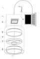
- FIG. 1 is a diagram showing an example of an imaging lens.
- the imaging lens 100 of the present embodiment is a pupil division imaging lens in which the pupil region is divided into two.
- the imaging lens 100 is an example of a lens device.
- the imaging lens 100 includes a lens barrel 110, a plurality of lens groups 120A and 120B, and a filter unit .
- the lens barrel 110 has a cylindrical shape.
- the lens groups 120A and 120B and the filter unit 130 are arranged at predetermined positions inside the lens barrel 110 .
- the lens groups 120A and 120B are composed of at least one lens. In FIG. 1, only two lens groups 120A and 120B are shown for convenience.
- the lens group 120A arranged on the front side of the filter unit 130 is defined as the first lens group
- the lens group 120B arranged on the rear side of the filter unit 130 is defined as the second lens group. , 120B.
- the "front side” means the "object side”
- the "back side” means the "image side”.
- a filter unit 130 is arranged in the optical path. More specifically, the filter unit 130 is arranged at or near the pupil position in the imaging lens 100 .
- the neighborhood of the pupil position refers to an area that satisfies the following equation.
- FIG. 2 is a front view showing a schematic configuration of the filter unit.
- the filter unit 130 is composed of a filter frame 132 and an optical filter held by the filter frame 132 .
- the filter frame 132 has a plate-like shape corresponding to the inner peripheral shape of the lens barrel 110, and has a plurality of windows. As shown in FIG. 2, the filter frame 132 of this embodiment has a disk-like shape and has two windows 132A and 132B.
- the filter frame 132 is an example of a frame.
- the two windows 132A and 132B are circular openings and arranged symmetrically with the optical axis Z interposed therebetween.
- the windows 132A and 132B are examples of openings.
- the two windows 132A and 132B are distinguished by defining the window 132A as the first window 132A and the window 132B as the second window 132B, as required.
- the imaging lens 100 has a pupil region divided into a plurality of regions by arranging the filter frame 132 at or near the pupil position. That is, the optical path is divided into multiple parts. In this embodiment, the pupil area is divided into two areas. That is, the optical path is split into two.
- band-pass filters (BPF) 134A and 134B and a band-stop filter (BSF) 136A are arranged in order from the object side (front side) in the window portions 132A and 132B.
- BPF band-pass filters
- BSF band-stop filter
- the bandpass filter 134A arranged in the first window portion 132A is assumed to be the first bandpass filter 134A
- the bandpass filter 134B arranged in the second window portion 132B is assumed to be the second bandpass filter 134B.
- a bandpass filter 134A, 134B placed in each window 132A, 132B is distinguished.
- the band-stop filter 136A arranged in the first window portion 132A is the first band-stop filter 136A
- the band-stop filter 136B arranged in the second window portion 132B is the second band-stop filter 136B.
- a bandstop filter 136A, 136B located at 132B is distinguished.
- a bandpass filter is an optical filter that transmits only light in a specific wavelength range by efficiently transmitting light in a specific wavelength range and efficiently blocking light in other wavelength ranges.
- the bandpass filters 134A, 134B arranged in the windows 132A, 132B have light transmission bands different from each other. Let the light transmission band of the first band-pass filter 134A be a first light transmission band ⁇ 1. Also, let the light transmission band of the second band-pass filter 134B be the second light transmission band ⁇ 2 ( ⁇ 1 ⁇ 2). In this embodiment, the second light transmission band ⁇ 2 is set on the longer wavelength side than the first light transmission band ⁇ 1.
- the bandpass filters 134A and 134B are examples of first optical filters.
- the reflective type has a function of reflecting a certain band and transmitting other bands.
- the absorptive type has a function of absorbing a certain band and transmitting other bands.
- a reflective band-pass filter has the advantage of realizing a narrow light transmission band and making a sharp transition from the transmission band to the transmission cut-off band. Therefore, when the imaging lens 100 is used in a multispectral camera, it is preferable to use a reflective bandpass filter.
- a reflective bandpass filter is used in the imaging lens 100 of the present embodiment.
- a band-stop filter is an optical filter that attenuates light in a specific wavelength range (stop band) to a very low level and transmits light in most other wavelengths with little intensity loss. Therefore, the bandstop filter has the opposite property of the bandpass filter.
- a band-stop filter is also called a band-rejection filter (BRF), a band-elimination filter (BEF), a band-elimination filter, a notch filter, and the like.
- Bandstop filters 136A and 136B are examples of second optical filters.
- an absorption bandstop filter is used as the bandstop filter.
- An absorptive bandstop filter has a light absorption band in a specific wavelength band, and blocks transmission of light in the light absorption band by absorption.
- a bandstop filter for example, consists of an optical filter with a layer containing a dye material that absorbs light in a specific wavelength range on a transparent substrate.
- a dye material By using a dye material, the required transmittance, absorptivity, and reflectance properties can be obtained.
- a bandstop filter made of a dye material can be easily laminated by thinning, and by combining a plurality of dye materials, desired transmittance characteristics, absorptance characteristics, and reflectance characteristics can be obtained.
- the first bandstop filter 136A and the second bandstop filter 136B have the following absorption characteristics.
- FIG. 3 is a graph showing an example of absorptance characteristics of the first bandstop filter.
- the solid line graph indicated by symbol BSF1 indicates the absorption rate characteristic of the first bandstop filter 136A.
- the broken line graph indicated by symbol BPF1 indicates the transmittance characteristic of the first bandpass filter 134A.
- a broken line graph indicated by symbol BPF2 indicates the transmittance characteristic of the second bandpass filter 134B.
- the first band-stop filter 136A has a characteristic of transmitting at least light in the wavelength band (first light transmission band ⁇ 1) transmitted by the first band-pass filter 134A. On the other hand, it has the characteristic of absorbing at least the light in the wavelength band (second light transmission band ⁇ 2) that is transmitted by the second bandpass filter 134B.
- FIG. 4 is a graph showing an example of absorptance characteristics of the second bandstop filter.
- the solid line graph indicated by symbol BSF2 indicates the absorption rate characteristic of the second bandstop filter 136B.
- the broken line graph indicated by symbol BPF1 indicates the transmittance characteristic of the first bandpass filter 134A.
- a broken line graph indicated by symbol BPF2 indicates the transmittance characteristic of the second bandpass filter 134B.
- the second band-stop filter 136B has a characteristic of transmitting at least light in the wavelength band (second light transmission band ⁇ 2) transmitted by the second band-pass filter 134B. On the other hand, it has a characteristic of absorbing at least light in the wavelength band (first light transmission band ⁇ 1) that is transmitted by the first bandpass filter 134A.
- the band-stop filter arranged in each window has a characteristic of transmitting at least the light in the wavelength range that is transmitted by the band-pass filter arranged in the same window.
- it has a characteristic of absorbing the light in the wavelength band transmitted by the band-pass filter arranged in at least one of the other windows.
- the band-stop filter placed in each window has a light absorption band in a wavelength region different from the light transmission band of the band-pass filter placed in the same window.
- the first bandstop filter 136A has a light absorption band in a wavelength band different from the first light transmission band ⁇ 1, as shown in FIG.
- the second bandstop filter 136B has a light absorption band in a wavelength region different from the second light transmission band ⁇ 2.
- the band-stop filter placed in each window has a light absorption band including the light transmission band of the band-pass filter placed in at least one of the other windows.
- the first bandstop filter 136A has optical absorption bands that include the second optical transmission band ⁇ 2, as shown in FIG. 4, the second bandstop filter 136B has a light absorption band including the first light transmission band .LAMBDA.1.
- a pupil-division imaging lens such as the imaging lens 100 of the present embodiment has the property that the optical paths split in the pupil region merge again on the image sensor.
- the light that has passed through the first window portion 132A reaches the image sensor while being restricted to the wavelength band ⁇ 1 by the first bandpass filter 134A.
- part of the light is reflected by the lens (second lens group 120B) behind the first bandpass filter 134A, the image sensor, and the like.
- Part of the reflected light enters the second window portion 132B.
- the light incident on the second window portion 132B reaches the image sensor after being reflected again by the second bandpass filter 134B arranged on the second window portion 132B.
- the wavelength band ⁇ 1 of the light reflected by the second bandpass filter 134B is different from the light transmission band (second light transmission band ⁇ 2) of the second bandpass filter 134B. Therefore, it is almost 100% reflected. This results in strong ghosts and flares.
- the light passing through the second window portion 132B reaches the image sensor while being restricted to the wavelength region ⁇ 2 by the second bandpass filter 134B.
- part of the light is reflected by the lens (second lens group 120B) behind the second bandpass filter 134B, the image sensor, and the like.
- Part of the reflected light enters the first window portion 132A.
- the light incident on the first window portion 132A reaches the image sensor after being reflected again by the first bandpass filter 134A arranged on the first window portion 132A.
- the wavelength band ⁇ 2 of the light reflected by the first bandpass filter 134A is different from the light transmission band (first light transmission band ⁇ 1) of the first bandpass filter 134A. Therefore, it is almost 100% reflected. This results in strong ghosts and flares.
- Antireflection coatings are generally used as a means of reducing ghosts and flares. However, antireflection coatings reduce reflectance by increasing transmittance. Therefore, for example, if an anti-reflection film for the wavelength band ⁇ 1 is applied to the second band-pass filter 134B, the light in the wavelength band ⁇ 1 is transmitted. As a result, the light transmission band of the second band-pass filter 134B transmits both the wavelength region ⁇ 1 and the wavelength region ⁇ 2, and achieves the desired transmittance characteristic (the transmittance characteristic that transmits only the wavelength region ⁇ 1). become unable.
- FIG. 5 is an explanatory diagram of the action of the imaging lens.
- the optical path of the light incident on the imaging lens 100 is divided into three by the filter unit 130, passes through the first window portion 132A and the second window portion 132B, and reaches the image sensor (not shown).
- the light incident on the first window portion 132A first passes through the first bandpass filter 134A. By passing through the first bandpass filter 134A, it is restricted to the wavelength region ⁇ 1. It then passes through a first bandstop filter 136A.
- the first bandstop filter 136A absorbs light in the wavelength band ⁇ 2, but transmits light in the wavelength band ⁇ 1. Therefore, the light in the wavelength region ⁇ 1 that has passed through the first band-pass filter 134A passes through the first band-stop filter 136A as it is.
- the light incident on the second window portion 132B first passes through the second bandpass filter 134B.
- the second bandpass filter 134B By passing through the second bandpass filter 134B, it is restricted to the wavelength region ⁇ 2. It then passes through a second bandstop filter 136B.
- the second bandstop filter 136B absorbs light in the wavelength band ⁇ 1, but transmits light in the wavelength band ⁇ 2. Therefore, the light in the wavelength region ⁇ 2 that has passed through the second bandpass filter 134B passes through the second bandstop filter 136B as it is.
- Part of the light that has passed through the first window portion 132A and the second window portion 132B is reflected by the lens (the second lens group 120B) or the like in the process of reaching the image sensor. Further, part of the light reaching the image sensor is reflected by the image sensor.
- the light in the wavelength region ⁇ 1 that passes through the first window portion 132A and is reflected by the lens, the image sensor, etc. also enters the second window portion 132B.
- a second bandstop filter 136B is arranged in the second window portion 132B.
- the second bandstop filter 136B transmits light in the wavelength band ⁇ 2, but absorbs light in the wavelength band ⁇ 1. Therefore, even if the light in the wavelength region ⁇ 1 reflected by the lens, the image sensor, etc. is incident on the second window portion 132B, it is absorbed before reaching the second bandpass filter 134B. Therefore, it is possible to suppress re-reflection of the light in the wavelength region ⁇ 1 reflected by the lens, the image sensor, or the like by the second bandpass filter 134B.
- the imaging lens 100 of the present embodiment even if the light that has passed through one window is reflected by the lens, the image sensor, or the like and enters the other window, It can be absorbed by band stop filters 136A and 136B provided in the part. As a result, re-reflection at the bandpass filters 134A and 134B can be suppressed, and the occurrence of ghost and flare can be suppressed.
- the configuration of the filter unit is different in the imaging lens in which the pupil region is divided into three. Therefore, only the configuration of the filter unit will be described here.
- FIG. 6 is a front view of a filter unit provided in an imaging lens with a pupil region divided into three. 7 is an exploded perspective view of the filter unit shown in FIG. 6.
- FIG. 6 is a front view of a filter unit provided in an imaging lens with a pupil region divided into three. 7 is an exploded perspective view of the filter unit shown in FIG. 6.
- the filter unit 140 of this example has a filter frame 142 with three windows 142A, 142B, and 142C.
- the windows 142A, 142B, and 142C are arranged at regular intervals on concentric circles about the optical axis.
- the three windows 142A, 142B, and 142C are distinguished by defining the window 142A as the first window 142A, the window 142B as the second window 142B, and the window 142C as the third window 142C.
- the imaging lens 100 has a pupil region divided into three regions by arranging the filter frame 142 at or near the pupil position. That is, the optical path is divided into three.
- Band-pass filters 144A, 144B, 144C and band-stop filters 146A, 146B, 146C are arranged in the respective window portions 142A, 142B, 142C.
- bandpass filters 144A, 144B, 144C and bandstop filters 146A, 146B, 146C are arranged in this order from the object side (front side) along the optical axis Z.
- the bandpass filter 144A arranged in the first window portion 142A is the first bandpass filter 144A
- the bandpass filter 144B arranged in the second window portion 142B is the second bandpass filter 144B
- the second bandpass filter 144B is arranged.
- the bandpass filters 144A, 144B, and 144C arranged in the respective windows 142A, 142B, and 142C are distinguished by setting the bandpass filter 144C arranged in the three window portions 142C as a third bandpass filter 144C.
- band-stop filter 146A arranged in the first window portion 142A is replaced with the first band-stop filter 146A
- the band-stop filter 146B arranged in the second window portion 142B is replaced with the second band-stop filter 146B and the third window portion 142C.
- the band-stop filter 146C to be placed is referred to as a third band-stop filter 146C
- the band-stop filters 146A, 146B, 146C placed in the windows 142A, 142B, 142C are distinguished.
- the bandpass filters 144A, 144B, 144C arranged in the windows 142A, 142B, 142C have light transmission bands different from each other.
- the light transmission band of the second band-pass filter 144B be the second light transmission band ⁇ 2 ( ⁇ 1 ⁇ 2).
- the light transmission band of the third band-pass filter 144C is assumed to be the third light transmission band ⁇ 3 ( ⁇ 1 ⁇ 3, ⁇ 2 ⁇ 3).
- the third light transmission band ⁇ 3 is set on the longer wavelength side than the second light transmission band ⁇ 2.
- the second light transmission band ⁇ 2 is set on the longer wavelength side than the first light transmission band ⁇ 1.
- a reflective bandpass filter is used for the bandpass filters 144A, 144B, and 144C.
- Absorptive band-stop filters are used for the band-stop filters 146A, 146B, and 146C.
- the bandstop filters 146A, 146B, 146C placed in the windows 142A, 142B, 142C have the following absorption characteristics, respectively.
- FIG. 8 is a graph showing an example of absorptance characteristics of the first bandstop filter.
- the solid line graph indicated by symbol BSF1 indicates the absorption rate characteristic of the first bandstop filter 146A.
- the dashed line graph indicated by symbol BPF1 indicates the transmittance characteristic of the first bandpass filter 144A.
- a broken line graph indicated by symbol BPF2 indicates the transmittance characteristic of the second bandpass filter 144B.
- a broken line graph indicated by symbol BPF3 indicates the transmittance characteristic of the third bandpass filter 144C.
- the first band-stop filter 146A has a characteristic of transmitting at least light in the wavelength band (first light transmission band ⁇ 1) transmitted by the first band-pass filter 144A.
- first light transmission band ⁇ 1 transmitted by the first band-pass filter 144A.
- second light transmission band ⁇ 2 transmitted by the second band-pass filter 144B
- third light transmission band ⁇ 3 transmitted by the third band-pass filter 144C It has the property of absorbing
- the first bandstop filter 146A can be realized with, for example, one dye material. That is, the wavelength band (first light transmission band ⁇ 1) transmitted by the first band-stop filter 136A is divided into two wavelength bands (second light transmission band ⁇ 2 and third light transmission band ⁇ 3) absorbed by the first band-stop filter 136A. ), it can be composed of one dye material. Specifically, it is configured using a pigment material that absorbs light in the second light transmission band ⁇ 2 and the light in the third light transmission band ⁇ 3.
- FIG. 9 is a graph showing an example of absorptance characteristics of the second bandstop filter.
- the solid line graph indicated by symbol BSF2 indicates the absorption rate characteristic of the second bandstop filter 146B.
- the dashed line graph indicated by symbol BPF1 indicates the transmittance characteristic of the first bandpass filter 144A.
- a broken line graph indicated by symbol BPF2 indicates the transmittance characteristic of the second bandpass filter 144B.
- a broken line graph indicated by symbol BPF3 indicates the transmittance characteristic of the third bandpass filter 144C.
- the second band-stop filter 146B has a characteristic of transmitting at least light in the wavelength band (second light transmission band ⁇ 2) transmitted by the second band-pass filter 144B.
- at least light in the wavelength band (first light transmission band ⁇ 1) transmitted by the first band-pass filter 144A and light in the wavelength band (third light transmission band ⁇ 3) transmitted by the third band-pass filter 144C It has the property of absorbing
- the second bandstop filter 146B is configured, for example, by combining two bandstop filters. Specifically, a band-stop filter (first and second band-stop filter) that absorbs light in the wavelength band (first light transmission band ⁇ 1) transmitted by the first band-pass filter 144A, and a third band-pass filter 144C A band-stop filter (second band-stop filter) that absorbs light in the wavelength band (third light transmission band ⁇ 3) that is transmitted by the come true.
- the first second bandstop filter is configured using a dye material that absorbs light in the first light transmission band ⁇ 1.
- the second second bandstop filter is configured using a dye material that absorbs light in the third light transmission band ⁇ 3.
- the solid line graph indicated by symbol BSF21 indicates the absorptance characteristics of the first and second band-stop filters.
- a solid line graph indicated by symbol BSF22 indicates the absorptivity characteristic of the second second band-stop filter.
- FIG. 10 is a graph showing an example of absorptance characteristics of the third bandstop filter.
- the solid line graph indicated by symbol BSF3 indicates the absorption rate characteristic of the third bandstop filter 146C.
- the dashed line graph indicated by symbol BPF1 indicates the transmittance characteristic of the first bandpass filter 144A.
- a broken line graph indicated by symbol BPF2 indicates the transmittance characteristic of the second bandpass filter 144B.
- a broken line graph indicated by symbol BPF3 indicates the transmittance characteristic of the third bandpass filter 144C.
- the third band-stop filter 146C has a characteristic of transmitting at least light in the wavelength band (third light transmission band ⁇ 3) transmitted by the third band-pass filter 144C.
- at least light in the wavelength band (first light transmission band ⁇ 1) transmitted by the first band-pass filter 144A and light in the wavelength band (second light transmission band ⁇ 2) transmitted by the second band-pass filter 144B It has the property of absorbing
- the third bandstop filter 146C can also be realized with one dye material. That is, by using a dye material that absorbs the light in the first light transmission band ⁇ 1 and the light in the second light transmission band ⁇ 2, one dye material can be used.
- the band-stop filter arranged in each window has the characteristic of transmitting at least the light in the wavelength range that is transmitted by the band-pass filter arranged in the same window.
- it has a characteristic of absorbing the light in the wavelength band transmitted by the band-pass filter arranged in at least one of the other windows. Therefore, as shown in FIG. 8, the first bandstop filter 146A has a light absorption band in a wavelength band different from the first light transmission band ⁇ 1, and has a second light transmission band ⁇ 2 and a third light transmission band ⁇ 3. It has a light absorption band in the wavelength range including Further, as shown in FIG.
- the second bandstop filter 146B has a light absorption band in a wavelength band different from the second light transmission band ⁇ 2, and has a first light transmission band ⁇ 1 and a third light transmission band ⁇ 3. It has a light absorption band in the wavelength range including Further, as shown in FIG. 10, the third bandstop filter 146C has a light absorption band in a wavelength band different from the third light transmission band ⁇ 3, and has a first light transmission band ⁇ 1 and a second light transmission band ⁇ 2. It has a light absorption band in the wavelength range including
- FIG. 11 is an explanatory diagram of the action of the imaging lens.
- the light incident on the imaging lens 100 passes through the first window portion 142A, the second window portion 142B, and the third window portion 142C by the filter unit 140, and reaches the image sensor (not shown).
- the light incident on the first window portion 142A first passes through the first bandpass filter 144A. By passing through the first bandpass filter 144A, it is restricted to the wavelength region ⁇ 1. It then passes through the first bandstop filter 146A.
- the first bandstop filter 146A absorbs light in the wavelength ranges ⁇ 2 and ⁇ 3, but transmits light in the wavelength range ⁇ 1. Therefore, the light in the wavelength band ⁇ 1 that has passed through the first band-pass filter 144A passes through the first band-stop filter 146A as it is.
- the light incident on the second window portion 142B also first passes through the second bandpass filter 144B. By passing through the second bandpass filter 144B, it is restricted to the wavelength region ⁇ 2. It then passes through a second bandstop filter 146B.
- the second band-stop filter 146B absorbs light in the wavelength bands ⁇ 1 and ⁇ 3, but transmits light in the wavelength band ⁇ 2. Therefore, the light in the wavelength band ⁇ 2 that has passed through the second band-pass filter 144B passes through the second band-stop filter 146B as it is.
- the light incident on the third window portion 142C also first passes through the third bandpass filter 144C.
- the third bandpass filter 144C By passing through the third bandpass filter 144C, it is restricted to the wavelength region ⁇ 3. It then passes through a third bandstop filter 146C.
- the third bandstop filter 146C absorbs light in the wavelength bands ⁇ 1 and ⁇ 2, but transmits light in the wavelength band ⁇ 3. Therefore, the light in the wavelength region ⁇ 3 that has passed through the third band-pass filter 144C passes through the third band-stop filter 146C as it is.
- Part of the light that has passed through the first window portion 142A, the second window portion 142B, and the third window portion 142C is reflected by the lens (the second lens group 120B) or the like in the process of reaching the image sensor. Further, part of the light reaching the image sensor is reflected by the image sensor.
- the light in the wavelength region ⁇ 1 that passes through the first window portion 142A and is reflected by the lens, the image sensor, etc. also enters the second window portion 142B and the third window portion 142C.
- a second bandstop filter 146B and a third bandstop filter 146C are arranged in the second window portion 142B and the third window portion 142C, respectively.
- the second bandstop filter 146B placed in the second window portion 142B transmits light in the wavelength range ⁇ 2, but absorbs light in the wavelength ranges ⁇ 1 and ⁇ 3. Therefore, even if the light in the wavelength region ⁇ 1 reflected by the lens, the image sensor, etc.
- a third band-stop filter 146C arranged in the third window portion 142C transmits light in the wavelength range ⁇ 3, but absorbs light in the wavelength ranges ⁇ 1 and ⁇ 2. Therefore, even if the light in the wavelength region ⁇ 1, which is the reflected light, is incident on the third window portion 142C, it is absorbed before reaching the third bandpass filter 144C. Therefore, it is possible to suppress the light in the wavelength region ⁇ 1, which is the light returned by the reflection, from being reflected again by the third bandpass filter 144C.
- the light in the wavelength region ⁇ 2 that has passed through the second window portion 142B is reflected by a lens, an image sensor, or the like and enters the first window portion 142A and the third window portion 142C.
- the first window portion 142A When light in the wavelength region ⁇ 2, which is light returned by reflection, enters the first window portion 142A, it is absorbed by the first band-stop filter 146A before reaching the first band-pass filter 144A. Therefore, it is possible to suppress re-reflection of the light in the wavelength band ⁇ 2 by the first bandpass filter 144A.
- the light in the wavelength region ⁇ 2 enters the third window portion 142C, it is absorbed by the third band-stop filter 146C before reaching the third band-pass filter 144C. Therefore, it is possible to suppress re-reflection of the light in the wavelength band ⁇ 2 by the third bandpass filter 144C.
- the light in the wavelength region ⁇ 3 that has passed through the third window portion 142C is reflected by the lens, the image sensor, etc., and enters the first window portion 142A and the second window portion 142B.
- the first window portion 142A When light in the wavelength region ⁇ 3, which is light returned by reflection, enters the first window portion 142A, it is absorbed by the first band-stop filter 146A before reaching the first band-pass filter 144A. Therefore, it is possible to suppress re-reflection of the light in the wavelength band ⁇ 3 by the first bandpass filter 144A.
- the light in the wavelength region ⁇ 3 enters the second window portion 142B, it is absorbed by the second band-stop filter 146B before reaching the second band-pass filter 144B. Therefore, it is possible to suppress the re-reflection of the light in the wavelength region ⁇ 3 by the second bandpass filter 144B.
- the imaging lens 100 of the present embodiment even if the light that has passed through one window is reflected by the lens, the image sensor, or the like and enters the other window, It can be absorbed by band stop filters 146A and 146B provided in the part. As a result, the re-reflection at the bandpass filters 144A and 144B can be suppressed, and the occurrence of ghost and flare can be suppressed.
- the shape (opening shape) of the window provided in the filter unit is circular, but the shape of the window is not limited to this.
- FIG. 12 is a diagram showing another example of the shape of the window provided in the filter unit.
- a disk-shaped filter frame 142 is equally divided into three in the circumferential direction to provide window portions 142A, 142B, and 142C having fan-shaped openings.
- Fan-shaped band-pass filters and band-stop filters are arranged in the windows 142A, 142B, and 142C, respectively.
- the functions of the bandpass filter and the bandstop filter can also be realized by a single optical filter.
- a layer or film having a bandpass filter function is provided on one side of the transparent substrate, and a layer or film having a bandstop filter function is provided on the other side of the transparent substrate.
- an optical filter having the functions of a band-pass filter and a band-stop filter can be realized with a single sheet.
- each optical filter can be joined by optical contact or the like and arranged in an integrated manner.
- the filter unit may be detachable from the lens barrel. This allows replacement of the filter unit.
- the optical filters attached to the respective windows can be replaced individually.
- the number and combination of wavelengths to be dispersed can be freely selected.
- one window is light-shielded and used when capturing an image spectrally divided into three wavelengths.
- the band-stop filter having a finite width in the light absorption band is used as the second optical filter.
- a filter is not limited to this.
- an optical filter having a property of absorbing light above or below a certain wavelength and transmitting light in other wavelength ranges can also be used.
- a sharp cut filter (SCF) can be exemplified as this type of optical filter.
- a sharp cut filter is also called a long pass filter.
- FIG. 13 is a graph showing an example of absorptance characteristics of a sharp cut filter.
- the figure shows an example of the absorptance characteristics of the sharp cut filter arranged in the first window in the filter unit (filter unit having three windows) shown in FIG. That is, it shows an example of absorptance characteristics of a sharp cut filter used in combination with the first bandpass filter 144A.
- the solid line graph indicated by symbol SCF1 indicates the absorptance characteristics of the sharp cut filter.
- the dashed line graph indicated by symbol BPF1 indicates the transmittance characteristic of the first bandpass filter 144A.
- a broken line graph indicated by symbol BPF2 indicates the transmittance characteristic of the second bandpass filter 144B.
- a broken line graph indicated by symbol BPF3 indicates the transmittance characteristic of the third bandpass filter 144C.
- the sharp cut filter of this example has a wavelength band (first light transmission band ⁇ 1) transmitted by the first band-pass filter 144A and a wavelength band (second light It has the characteristic of absorbing light on the longer wavelength side with the wavelength between the transmission band ⁇ 2) as the boundary.
- first light transmission band ⁇ 1 transmitted by the first band-pass filter 144A can be transmitted
- second light transmission band ⁇ 2 transmitted by the second band-pass filter 144B can be transmitted. It can absorb light and light in the wavelength band (third light transmission band ⁇ 3) transmitted by the third band-pass filter 144C.
- FIG. 14 is a graph showing an example of absorptivity characteristics of a second optical filter when a bandstop filter and a sharp cut filter are combined to form one second optical filter.
- This figure shows an example of absorptance characteristics of the second optical filter arranged in the first window part in the filter unit shown in FIG.
- the dashed line graph indicated by symbol BPF1 indicates the transmittance characteristic of the first bandpass filter 144A.
- a broken line graph indicated by symbol BPF2 indicates the transmittance characteristic of the second bandpass filter 144B.
- a broken line graph indicated by symbol BPF3 indicates the transmittance characteristic of the third bandpass filter 144C.
- the third light having desired absorptance characteristics as a whole can be obtained. 2 optical filters are realized.
- the solid line graph indicated by symbol BSF11 indicates the absorptance characteristics of the bandstop filter.
- the bandstop filter has a light absorption band with a finite width in the wavelength band including the second light transmission band ⁇ 2.
- the solid line graph indicated by symbol SCF12 indicates the absorptance characteristics of the sharp cut filter.
- the sharp cut filter has a characteristic of absorbing light on the longer wavelength side with respect to the wavelength set on the shorter wavelength side than the third light transmission band ⁇ 3.
- a bandstop filter and a sharp cut filter are combined to realize a second optical filter having a desired absorptance characteristic. It is also possible to realize a second optical filter with an absorption characteristic of .
- FIG. 15 is a graph showing an example of absorptance characteristics of the second optical filter.
- the figure shows an example of preferable absorptance characteristics when a band-stop filter having a finite light absorption band is used as the second optical filter.
- the wavelength at which the absorptivity peaks is ⁇ abs
- the absorptance at the absorptance peak wavelength ⁇ abs is ⁇ max.
- the second optical filter preferably has an absorptance ⁇ max of 0.8 or more at the absorptance peak wavelength ⁇ abs ( ⁇ max ⁇ 0.8).
- ⁇ is the absorptance
- ⁇ is the transmittance
- ⁇ is the reflectance
- there is a relationship of ⁇ + ⁇ + ⁇ 1.
- FIG. 15 shows an example of a bandstop filter, but in the case of using a sharp cut filter as the second optical filter, it is also preferable that the absorptance ⁇ max at the absorptance peak wavelength ⁇ abs is 0.8 or more. .
- the width of the wavelength at which the absorptance ⁇ max at the absorptance peak wavelength ⁇ abs is 50% ( ⁇ max/2) is ⁇ abs
- the width ⁇ abs is preferably 20 nm or more and 200 nm or less (20 [nm] ⁇ ⁇ abs ⁇ 200 [nm]).
- the width of the wavelength at which the absorptance is 50% (half value) at the absorptance peak wavelength refers to the bandwidth between the long wavelength side and the short wavelength side where the absorptance is 50% of the peak value (so-called full width at half maximum).
- the full width at half maximum ( ⁇ abs) is preferably 20 nm or more and 200 nm or less.
- FIG. 16 is a graph showing an example of transmittance characteristics of the second optical filter.
- the figure shows an example of preferable transmittance characteristics when a band-stop filter having a finite light absorption band is used as the second optical filter.
- the wavelength at which the transmittance peaks (transmittance peak wavelength) is ⁇ tra
- the transmittance at the transmittance peak wavelength ⁇ tra is ⁇ max.
- the second optical filter preferably has a transmittance ⁇ max of 0.8 or more at the transmittance peak wavelength ⁇ tra ( ⁇ max ⁇ 0.8).
- the second optical filter gives ⁇ abs an absorption characteristic for the purpose of preventing reflected light, but by giving it a high transmittance near the wavelength actually used (the wavelength to be transmitted), it is possible to suppress the luminance reduction.
- FIG. 17 is a graph showing another example of transmittance characteristics of the second optical filter.
- the figure shows an example of preferable transmittance characteristics when a sharp cut filter is used as the second optical filter.
- the transmittance ⁇ max at the transmittance peak wavelength ⁇ tra is preferably 0.8 or more.
- FIG. 18 is a graph showing an example of reflectance characteristics of the second optical filter.
- the wavelength at which the reflectance peaks is defined as ⁇ ref
- the transmittance at the reflectance peak wavelength ⁇ ref is defined as ⁇ max.
- the second optical filter preferably has a reflectance ⁇ max of less than 0.1 at the reflectance peak wavelength ⁇ ref ( ⁇ max ⁇ 0.1).
- FIG. 19 is a graph showing an example of transmittance characteristics of a second optical filter used in combination with the first optical filter.
- the figure shows an example in which a bandpass filter is used as the first optical filter and a bandstop filter is used as the second optical filter.
- ⁇ BPF be the wavelength at which the transmittance of the bandpass filter peaks (transmittance peak wavelength) in the so-called visible range to the near-infrared range (400 to 1000 [nm]).
- ⁇ BSF( ⁇ BPF) be the transmittance at the wavelength corresponding to the transmittance peak wavelength ⁇ BPF.
- the bandstop filter as the second optical filter preferably has a transmittance ⁇ BSF( ⁇ BPF) at a wavelength corresponding to the transmittance peak wavelength ⁇ BPF of 0.8 or more ( ⁇ BSF( ⁇ BPF) ⁇ 0.8).
- FIG. 20 is a graph showing another example of transmittance characteristics of the second optical filter used in combination with the first optical filter.
- the figure shows an example in which a bandpass filter is used as the first optical filter and a sharp cut filter is used as the second optical filter.
- ⁇ SCF( ⁇ BPF) the transmittance at the wavelength corresponding to the transmittance peak wavelength ⁇ BPF.
- the transmittance ⁇ SCF ( ⁇ BPF) at the wavelength corresponding to the transmittance peak wavelength ⁇ BPF is preferably 0.8 or more ( ⁇ SCF ( ⁇ BPF) ⁇ 0.8 ).
- Transmittance characteristics of the second optical filter arranged in each region in an imaging lens having a pupil region divided into a plurality of regions In an imaging lens having a pupil region divided into a plurality of regions, The transmittance characteristic of the second optical filter is set as follows.
- the pupil region is divided into three. That is, it is assumed that the optical path is divided into three.
- the filter unit is provided with three windows.
- ⁇ BPFj be the transmittance peak wavelength of the band-pass filter placed in the j-th window.
- the band-stop filter placed in each window preferably has an absorption characteristic that satisfies the following conditions. ⁇ BSFi( ⁇ BPFj) ⁇ 0.8 However, i ⁇ j
- the band-stop filter placed in each window should have an absorptance of 0.8 or more at the wavelength corresponding to the transmittance peak wavelength of the band-pass filter placed in the other window (optical path). preferable.
- FIG. 21 is a graph showing an example of transmittance characteristics of a band-stop filter used in combination with a band-pass filter in the third window.
- the band-stop filter placed in the third window has absorptivity ⁇ BSF3 ( ⁇ BPF1) at a wavelength corresponding to the transmittance peak wavelength ⁇ BPF1 of the band-pass filter placed in the first window,
- the absorptance ⁇ BSF3 ( ⁇ BPF2) at the wavelength corresponding to the transmittance peak wavelength ⁇ BPF2 of the band-pass filter arranged in the second window portion is a value close to the peak. That is, near the wavelength corresponding to the transmittance peak wavelength ⁇ BPF1 of the bandpass filter placed in the first window and near the wavelength corresponding to the transmittance peak wavelength ⁇ BPF2 of the bandpass filter placed in the second window It has peak characteristics.
- FIG. 22 is a graph showing an example of transmittance characteristics when using a sharp cut filter as the second optical filter.
- ⁇ BPF1 be the transmittance peak wavelength of the band-pass filter placed in the first window
- ⁇ BPF2 be the transmittance peak wavelength of the band-pass filter placed in the second window.
- the absorptance at the wavelength corresponding to the transmittance peak wavelength ⁇ BPF1 of the band-pass filter placed in the first window is assumed to be ⁇ SCF3 ( ⁇ BPF1)
- ⁇ SCF3 ( ⁇ BPF2) be the absorptance at the wavelength corresponding to the transmittance peak wavelength ⁇ BPF2 of the arranged band-pass filter.
- the sharp cut filter placed in the third window has absorptivity ⁇ SCF3 ( ⁇ BPF1) at a wavelength corresponding to the transmittance peak wavelength ⁇ BPF1 of the bandpass filter placed in the first window,
- the absorptance ⁇ SCF3 ( ⁇ BPF2) at the wavelength corresponding to the transmittance peak wavelength ⁇ BPF2 of the band-pass filter arranged in the second window portion is a value close to the peak. That is, near the wavelength corresponding to the transmittance peak wavelength ⁇ BPF1 of the bandpass filter placed in the first window and near the wavelength corresponding to the transmittance peak wavelength ⁇ BPF2 of the bandpass filter placed in the second window It has peak characteristics.
- the second optical filter having a predetermined absorptance characteristic in each window (the first optical filter arranged in another window has a constant absorptivity at or near the wavelength corresponding to the transmittance peak wavelength of the first optical filter).
- the light passing through the first window is limited to light near the wavelength ⁇ BPF1 by the second optical filter arranged in the first window.
- the second optical filter placed in the third window has a peak absorptivity at or near the wavelength corresponding to the wavelength ⁇ BPF1.
- the light passing through the first window is limited to light near the wavelength ⁇ BPF1 by the second optical filter arranged in the first window.
- the first optical filter and the second optical filter arranged in the first window section substantially transmit light in the vicinity of the wavelength ⁇ BPF1. Therefore, the light is not reflected again by the first optical filter and the second optical filter arranged in the first window. Therefore, it does not contribute to an increase in the occurrence of ghosts and flares.
- incident light Light that passes through the second window, is reflected by the lens, the image sensor, etc., and enters the second window, and passes through the third window, is reflected by the lens, the image sensor, etc., and enters the third window. The same applies to incident light.
- the second optical filter having a predetermined absorptivity characteristic By arranging the second optical filter having a predetermined absorptivity characteristic in the window portion where the first optical filter is arranged in this way, the reflection at the first optical filter is reduced. Thereby, reduction of ghost and flare is achieved in the optical system as a whole.
- a multispectral camera system is a system that simultaneously captures an image (multispectral image) separated into a plurality of wavelengths.
- a polarized light system is a multispectral camera system that uses polarized light.
- the imaging lens used in the polarized multispectral camera system has a polarizing filter arranged in each window of the filter unit.
- a polarizing filter arranged in each window of the filter unit.
- the configuration of the imaging lens is the same as that of the imaging lens of the above embodiment except that a polarizing filter is arranged in each window of the filter unit. Therefore, only the configuration of the filter unit will be described here.
- FIG. 23 is an exploded perspective view of a filter unit provided in an imaging lens for a polarized multispectral camera system.
- the filter unit 150 of this example has a filter frame 152 with three windows 152A, 152B, and 152C.
- the windows 152A, 152B, and 153C are arranged at regular intervals on concentric circles centered on the optical axis.
- the three windows 152A, 152B, and 152C are distinguished by defining the window 152A as the first window 152A, the window 152B as the second window 152B, and the window 152C as the third window 152C.
- the imaging lens 100 has a pupil region divided into three regions by arranging the filter frame 152 at or near the pupil position. That is, the optical path is divided into three.
- Band-pass filters 154A, 154B, 154C, band-stop filters 156A, 156B, 156C, and polarizing filters 158A, 158B, 158C are arranged in the respective window portions 152A, 152B, 152C.
- polarizing filters 158A, 158B, 158C, bandpass filters 154A, 154B, 154C, and bandstop filters 156A, 156B, 156C are arranged in this order from the object side (front side) along the optical axis Z. be.
- the bandpass filter 154A arranged in the first window portion 152A is the first bandpass filter 154A
- the bandpass filter 154B arranged in the second window portion 152B is the second bandpass filter 154B
- the second bandpass filter 154B is arranged.
- the bandpass filters 154A, 154B, and 154C arranged in the windows 152A, 152B, and 152C are distinguished by using the bandpass filter 154C arranged in the three window portions 152C as a third bandpass filter 154C.
- band-stop filter 156A arranged in the first window portion 152A is replaced with the first band-stop filter 156A
- the band-stop filter 156B arranged in the second window portion 152B is replaced with the second band-stop filter 156B
- the third window portion 152C is replaced with the band-stop filter 156C to be placed.
- the band-stop filter 156C to be placed is referred to as a third band-stop filter 156C
- the band-stop filters 156A, 156B, 156C placed in the windows 152A, 152B, 152C are distinguished.
- the polarizing filter 158A arranged in the first window portion 152A is the first polarizing filter 158A
- the polarizing filter 158B arranged in the second window portion 152B is the second polarizing filter 158B
- the polarizing filter 158B is arranged in the third window portion 152C.
- the filter 158C is a third polarizing filter 158C to distinguish the polarizing filters 158A, 158B, 158C arranged in the windows 152A, 152B, 152C.
- the bandpass filters 154A, 154B, 154C arranged in the windows 152A, 152B, 152C have light transmission bands different from each other.
- the light transmission band of the first band-pass filter 154A be a first light transmission band ⁇ 1.
- the light transmission band of the second bandpass filter 154B is assumed to be a second light transmission band ⁇ 2 ( ⁇ 1 ⁇ 2).
- the light transmission band of the third band-pass filter 154C is assumed to be the third light transmission band ⁇ 3 ( ⁇ 1 ⁇ 3, ⁇ 2 ⁇ 3).
- the third light transmission band ⁇ 3 is set on the longer wavelength side than the second light transmission band ⁇ 2.
- the second light transmission band ⁇ 2 is set on the longer wavelength side than the first light transmission band ⁇ 1.
- a reflective bandpass filter is used for the bandpass filters 154A, 154B, and 154C.
- the band-stop filters 156A, 156B, 156C arranged in the respective windows 152A, 152B, 152C have the characteristic of transmitting at least the light in the wavelength range that is transmitted by the band-pass filters arranged in the same window. On the other hand, it has a characteristic of absorbing the light in the wavelength band transmitted by the band-pass filter arranged in at least one of the other windows. Specifically, it is composed of an absorptive band-stop filter having the following optical characteristics.
- the first band-stop filter 146A has a characteristic of transmitting at least light in the wavelength band (first light transmission band ⁇ 1) transmitted by the first band-pass filter 144A.
- first light transmission band ⁇ 1 transmitted by the first band-pass filter 144A.
- second light transmission band ⁇ 2 transmitted by the second band-pass filter 144B
- third light transmission band ⁇ 3 transmitted by the third band-pass filter 144C (See FIG. 8).
- the second band-stop filter 146B has a characteristic of transmitting at least light in the wavelength band (second light transmission band ⁇ 2) transmitted by the second band-pass filter 144B.
- second light transmission band ⁇ 2 transmitted by the second band-pass filter 144B.
- at least light in the wavelength band (first light transmission band ⁇ 1) transmitted by the first band-pass filter 144A and light in the wavelength band (third light transmission band ⁇ 3) transmitted by the third band-pass filter 144C See FIG. 9).
- the third band-stop filter 146C has a characteristic of transmitting at least light in the wavelength band (third light transmission band ⁇ 3) transmitted by the third band-pass filter 144C.
- at least light in the wavelength band (first light transmission band ⁇ 1) transmitted by the first band-pass filter 144A and light in the wavelength band (second light transmission band ⁇ 2) transmitted by the second band-pass filter 144B See FIG. 10).
- Polarizing filters 158A, 158B, and 158C having different transmission axis angles are provided in the windows 152A, 152B, and 152C, respectively.
- a polarizing filter 158A provided in the first window portion 152A has a transmission axis set at a first angle ⁇ 1.
- a polarizing filter 158B provided in the second window portion 152B has a transmission axis set at a second angle ⁇ 2 ( ⁇ 2 ⁇ 1).
- a polarizing filter 158C provided in the third window portion 152C has a transmission axis set at a third angle ⁇ 3 ( ⁇ 3 ⁇ 1, ⁇ 3 ⁇ 1).
- FIG. 24 is a diagram showing an example of a polarizing filter provided in each window of the filter unit. This figure shows the settings of the transmission axes of the polarizing filters 158A, 158B, and 158C when the filter unit 150 is viewed from the object side.
- the transmission axis of the polarizing filter 158B provided in the second window portion 152B is 0°.
- the angle is 0° when parallel to the X axis, and the counterclockwise direction as viewed from the object side (front side) is the plus (+) direction. Therefore, when the transmission axis is 60°, it means that the transmission axis is inclined 60° counterclockwise with respect to the X axis. Also, the transmission axis of 120° means that the transmission axis is tilted counterclockwise by 120° with respect to the X-axis. 120° is synonymous with -60°. That is, when the transmission axis is 120 degrees, it means that the transmission axis is tilted clockwise by 60 degrees with respect to the X axis.
- the X-axis is an axis set on a plane orthogonal to the optical axis Z.
- the axis perpendicular to the X axis is the Y axis.
- the image sensor provided in the camera body of the multispectral camera system is arranged such that the upper and lower sides of its light receiving surface are parallel to the X-axis. Also, the left and right sides are arranged parallel to the Y-axis.
- Both reflective and absorptive polarizing filters 158A, 158B, and 158C can be used, but it is preferable to use absorptive filters from the viewpoint of ghost suppression.
- the action of the imaging lens of this example configured as described above is as follows.
- the optical path of the light incident on the imaging lens is divided into three by the filter unit 150, passes through the first window 152A, the second window 152B and the third window 152C, and reaches the image sensor (not shown).
- the light incident on the first window portion 152A passes through the first polarizing filter 158A, the first bandpass filter 154A, and the first bandstop filter 156A arranged in the first window portion 152A, and passes through the first window portion 152A. emitted.
- the light incident on the first window portion 152A passes through the first polarizing filter 158A, the first bandpass filter 154A, and the first bandstop filter 156A in this order.
- the first polarizing filter 158A the light becomes linearly polarized light with an azimuth angle of 0°. Then, it is restricted to the wavelength band ⁇ 1 by passing through the first bandpass filter 154A.
- the first bandstop filter 156A absorbs light in the wavelength bands ⁇ 2 and ⁇ 3, but transmits light in the wavelength band ⁇ 1. Therefore, the light in the wavelength band ⁇ 1 that has passed through the first band-pass filter 154A passes through the first band-stop filter 156A as it is. Therefore, linearly polarized light having a wavelength range ⁇ 1 and an azimuth angle of 0° is emitted from the first window portion 152A.
- the light incident on the second window portion 152B passes through the second polarizing filter 158B, the second bandpass filter 154B, and the second bandstop filter 156B, which are arranged in the second window portion 152B, and exits the second window portion 152B. emitted.
- the light incident on the second window portion 152B passes through the second polarizing filter 158B, the second bandpass filter 154B, and the second bandstop filter 156B in this order.
- the second polarizing filter 158B the light becomes linearly polarized light with an azimuth angle of 60°.
- the second bandpass filter 154B it is restricted to the wavelength region ⁇ 2.
- the second band-stop filter 156B absorbs light in the wavelength bands ⁇ 1 and ⁇ 3, but transmits light in the wavelength band ⁇ 2. Therefore, the light in the wavelength region ⁇ 2 that has passed through the second bandpass filter 154B passes through the second bandstop filter 156B as it is. Therefore, linearly polarized light having a wavelength region ⁇ 2 and an azimuth angle of 60° is emitted from the second window portion 152B.
- the light incident on the third window portion 152C passes through the third polarizing filter 158C, the third bandpass filter 154C, and the third bandstop filter 156C, which are arranged in the third window portion 152C, and exits the third window portion 152C. emitted.
- the light incident on the third window portion 152C passes through the third polarizing filter 158C, the third bandpass filter 154C, and the third bandstop filter 156C in this order.
- the third polarizing filter 158C the light becomes linearly polarized light with an azimuth angle of 120°.
- the third bandpass filter 154C it is restricted to the wavelength region ⁇ 2.
- the third bandstop filter 156C absorbs light in the wavelength bands ⁇ 1 and ⁇ 2, but transmits light in the wavelength band ⁇ 3. Therefore, the light in the wavelength region ⁇ 3 that has passed through the third band-pass filter 154C passes through the third band-stop filter 156C as it is. Therefore, linearly polarized light having a wavelength region ⁇ 3 and an azimuth angle of 120° is emitted from the third window portion 152C.
- the imaging lens of this example by arranging the polarizing filters 158A, 158B, and 158C in the window portions 152A, 152B, and 152C of the filter unit 150, predetermined light is emitted from the window portions 152A, 152B, and 152C. is obtained. Note that the effect of suppressing ghost and flare by arranging the bandstop filters 156A, 156B, and 156C is the same as that of the imaging lens 100 of the above embodiment.
- the band-pass filter, the band-stop filter, and the polarizing filter are arranged along the optical axis in the order of the polarizing filter, the band-pass filter, and the band-stop filter from the object side in each window.
- the order of arranging the optical filters is not limited to this.
- a bandpass filter, a bandstop filter, and a polarizing filter may be arranged in this order from the object side along the optical axis.
- a bandpass filter, a polarizing filter, and a bandstop filter may be arranged in this order from the object side along the optical axis.
- the band-pass filter, band-stop filter, and polarizing filter arranged in each window be arranged without interposing an air layer.
- a sharp cut filter can be used instead of the band stop filter.
- the number of windows (the number of divisions of the pupil region) provided in the filter unit is set according to the number of wavelengths to be dispersed. For example, at least two windows are provided when splitting into two wavelengths and imaging. Moreover, at least four windows are provided in the case of splitting into four wavelengths and imaging.
- Multispectral camera system Next, a multispectral camera system using an imaging lens to which the present invention is applied will be described.
- the multispectral camera system is a system that simultaneously captures images that are separated into multiple wavelengths.
- FIG. 25 is a diagram showing a schematic configuration of a multispectral camera system.
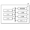
- the multispectral camera system 1 of the present embodiment is mainly composed of a multispectral camera 10 and a signal processing device 300.
- the multispectral camera 10 is composed of an imaging lens 100 and a camera body 200 .
- Multispectral camera 10 is an example of an imaging device.
- An imaging lens including a filter unit 150 shown in FIG. 23 is used for the imaging lens 100 . That is, the filter frame 152 has three windows 152A, 152B, and 152C, and band-pass filters 154A, 154B, and 154C, band-stop filters 156A, 156B, and 156C, and polarizing filters 158A, An imaging lens with a filter unit 150 in which 158B, 158C are arranged is used.
- camera body 200 has image sensor 210 .
- the image sensor 210 is arranged on the optical axis of the imaging lens 100 and receives light that has passed through the imaging lens 100 .
- This image sensor 210 is composed of a polarization image sensor.
- a polarization image sensor is an image sensor equipped with a polarizer, and a polarizer is provided for each pixel.
- a polarizer is provided, for example, between the microlens and the photodiode. Note that this type of polarization image sensor is publicly known (see, for example, International Publication No. 2020/071253), so detailed description thereof will be omitted.
- the direction (angle of the transmission axis) of the polarizer mounted on the polarization image sensor is selected according to the number of wavelengths to be imaged.
- images are picked up by spectroscopy into three wavelengths.
- a polarization image sensor with at least three polarizers is used.
- a polarization image sensor with polarizers in four directions is used.
- FIG. 26 is a diagram showing an example of arrangement of pixels and polarizers in a polarization image sensor.
- a polarizer with a transmission axis angle of ⁇ 1 is a first polarizer
- a polarizer with a transmission axis angle of ⁇ 2 is a second polarizer
- a polarizer with a transmission axis angle of ⁇ 3 is a third polarizer
- a transmission axis is A polarizer having an angle of ⁇ 4 is defined as a fourth polarizer.
- the angle ⁇ 1 of the transmission axis of the first polarizer is 0°
- the angle ⁇ 2 of the transmission axis of the second polarizer is 45°
- the angle ⁇ 3 of the transmission axis of the third polarizer is is set to 90°
- the angle ⁇ 4 of the transmission axis of the fourth polarizer is set to 135°.
- the pixel P1 with the first polarizer is the first pixel
- the pixel P2 with the second polarizer is the second pixel
- the pixel P3 with the third polarizer is the third pixel
- the fourth polarizer. is the fourth pixel.
- a 2 ⁇ 2 pixel group consisting of a first pixel P1, a second pixel P2, a third pixel P3 and a fourth pixel P4 is defined as one unit (pixel unit) PU, and this pixel unit PU is arranged along the X axis and the Y axis. are repeatedly arranged along the
- a polarization image sensor equipped with polarizers in four directions can capture polarized images in four directions in one shot.
- the image sensor 210 is composed of, for example, a CMOS (Complementary Metal Oxide Semiconductor) type that includes a drive section, an ADC (Analog to Digital Converter), and a signal processing section.
- CMOS Complementary Metal Oxide Semiconductor
- ADC Analog to Digital Converter
- the image sensor 210 operates by being driven by a built-in driver.
- the signal of each pixel is converted into a digital signal by the built-in ADC and output.
- the signal of each pixel is output after undergoing correlated double sampling processing, gain processing, correction processing, etc. by the built-in signal processing unit.
- the signal processing may be performed after conversion into a digital signal, or may be performed before conversion into a digital signal.
- the camera body 200 includes an output unit (not shown) that outputs image data captured by the image sensor 210, a camera control unit (not shown) that controls the overall operation of the camera body 200, and the like.
- the camera control section is composed of, for example, a processor.
- the processor functions as a camera control section by executing a predetermined control program.
- the image data output from the camera body 200 is so-called RAW image data. That is, unprocessed image data.
- This RAW image data is processed by the signal processing device 300 to generate an image spectrally divided into a plurality of wavelengths.
- the signal processing device 300 processes image data (RAW image data) output from the camera body 200 to generate an image spectrally divided into a plurality of wavelengths. More specifically, an image of a wavelength band corresponding to the light transmission band of the bandpass filter provided in each window of the imaging lens 100 is generated. In the present embodiment, an image (first image) of a wavelength band (first wavelength band ⁇ 1) corresponding to the first light transmission band ⁇ 1 and a wavelength band (second wavelength 2) image (second image) and an image (third image) of the wavelength band (third wavelength band ⁇ 3) corresponding to the third light transmission band ⁇ 3 are generated. .
- FIG. 27 is a diagram showing an example of the hardware configuration of the signal processing device.
- the signal processing device 300 includes a CPU (Central Processing Unit) 311, a ROM (Read Only Memory) 312, a RAM (Random Access Memory) 313, an auxiliary storage device 314, an input device 315, an output device 316 and An input/output interface 317 and the like are provided.
- a signal processing device 300 is configured by, for example, a general-purpose computer such as a personal computer.
- the signal processing device 300 functions as a signal processing device when the CPU 311, which is a processor, executes a predetermined program (signal processing program). Programs executed by the CPU 311 are stored in the ROM 312 or the auxiliary storage device 314 .
- the auxiliary storage device 314 constitutes a storage unit of the signal processing device 300 .
- the auxiliary storage device 314 is composed of, for example, an HDD (Hard Disk Drive), an SSD (Solid State Drive), or the like.
- the input device 315 constitutes an operation unit of the signal processing device 300 .
- the input device 315 is composed of, for example, a keyboard, mouse, touch panel, and the like.
- the output device 316 constitutes the display section of the signal processing device 300 .
- the output device 316 is configured by, for example, a display such as a liquid crystal display (Liquid Crystal Display) or an organic EL display (Organic Light Emitting Diode display).
- a display such as a liquid crystal display (Liquid Crystal Display) or an organic EL display (Organic Light Emitting Diode display).
- the input/output interface 317 constitutes a connection section of the signal processing device 300 .
- the signal processing device 300 is connected to the camera body 200 via the input/output interface 317 .
- FIG. 28 is a block diagram of the main functions of the signal processing device.
- the signal processing device 300 has functions such as an image data acquisition section 320, an image generation section 330, an output control section 340, a recording control section 350, and the like. These functions are realized by the CPU 311 executing a predetermined program.
- the image data acquisition unit 320 acquires image data obtained by imaging from the camera body 200 .
- the image data obtained from the camera body 200 is RAW image data.
- the image generation unit 330 performs predetermined signal processing on the image data acquired by the image data acquisition unit 320 to obtain wavelengths corresponding to the light transmission bands of the band-pass filters provided in the respective windows of the imaging lens 100. generate an image of the area.
- an image of the first wavelength band ⁇ 1 (first image), an image of the second wavelength band ⁇ 2 (second image), and an image of the third wavelength band ⁇ 3 (third image) to generate
- the image generation unit 330 performs processing for removing interference in units of pixel units from the image data acquired by the image data acquisition unit 320, and generates images in the respective wavelength ranges ⁇ 1, ⁇ 2, and ⁇ 3. This process will be outlined below.
- a polarization image sensor equipped with polarizers in four directions can capture polarized images in four directions in one shot.
- the polarization images in the four directions contain image components of respective wavelength regions ⁇ 1, ⁇ 2, and ⁇ 3 at a predetermined ratio (interference rate).
- the interference rate is determined by the angle of the transmission axis of the polarizing filter provided in each window of the filter unit 120 and the angle of the transmission axis of the polarizer provided in each pixel, and is known. By using the information on the interference rate, an image of each wavelength band can be generated.
- x1 be the pixel value of the first pixel P1
- x2 be the pixel value of the second pixel P2
- x3 be the pixel value of the third pixel P3
- x4 be the pixel value of the fourth pixel P4 in the image captured by the image sensor 210.
- X1 be the pixel value of the corresponding pixel of the generated first image
- X2 be the pixel value of the corresponding pixel of the second image
- X3 be the pixel value of the corresponding pixel of the third image.
- b11 is the rate at which light in the first wavelength range ⁇ 1 is received by the first pixel P1
- b12 is the rate at which light in the second wavelength range ⁇ 2 is received by the first pixel P1
- light in the third wavelength range ⁇ 3 is received by the first pixel P1 is b13
- the following relationship holds between X1, X2, X3 and x1.
- b11*X1+b12*X2+b13*X3 x1 (Formula 1)
- b21 is the rate at which light in the first wavelength range ⁇ 1 is received by the second pixel P2
- b22 is the rate at which light in the second wavelength range ⁇ 2 is received by the second pixel P
- b22 is the rate at which the light in the second wavelength range ⁇ 2 is received by the second pixel P2
- light received by the second pixel P2 is b23, the following relationship holds between X1, X2, X3 and x2.
- b21*X1+b22*X2+b23*X3 x2 (Formula 2)
- b31 is the rate at which light in the first wavelength range ⁇ 1 is received by the third pixel P3
- b32 is the rate at which light in the second wavelength range ⁇ 2 is received by the third pixel P3
- b32 is the rate at which the light in the second wavelength range ⁇ 2 is received by the third pixel P3.
- light received by the third pixel P3 is b33, the following relationship holds between X1, X2, X3 and x3.
- b31*X1+b32*X2+b33*X3 x3 (Formula 3)
- b41 is the rate at which the light in the first wavelength range ⁇ 1 is received by the fourth pixel P
- b42 is the rate at which the light in the second wavelength range ⁇ 2 is received by the fourth pixel P4
- light received by the fourth pixel P4 is b43, the following relationship holds between X1, X2, X3 and x4.
- b41*X1+b42*X2+b43*X3 x4 (Formula 4)
- the pixel values X1, X2, and X3 of the corresponding pixels of the first, second, and third images can be obtained.
- the above simultaneous equations can be represented by a formula using a matrix.
- X1, X2, and X3 can be calculated by multiplying both sides by the inverse matrix of the matrix.
- the signal processing device 300 holds each element of this inverse matrix as a coefficient group.
- the coefficient group information is stored, for example, in the auxiliary storage device 314 .
- the image generator 330 acquires information on the coefficient group from the auxiliary storage device 314 and generates an image of each wavelength band.
- the output control unit 340 controls the output of the images (first image, second image and third image) of each wavelength region generated by the image generation unit 330 .
- output (display) to the display which is the output device 316, is controlled.
- the recording control unit 350 controls recording of images in each wavelength band generated by the image generating unit 330 in accordance with instructions from the user.
- the generated image of each wavelength band is recorded in the auxiliary storage device 314 .
- the multispectral camera system 1 of the present embodiment configured as described above, it is possible to simultaneously capture an image spectrally divided into three wavelengths.
- the three wavelengths are the light transmission bands (first light transmission band ⁇ 1, second light transmission band ⁇ 2 and third corresponds to the light transmission band .LAMBDA.3). Therefore, by changing the band-pass filters arranged in the windows 152A, 152B, and 152C, it is possible to capture images of different combinations of wavelength bands.
- the imaging lens to which the present invention is applied can also be used for multispectral camera systems other than the polarization method.
- it can also be used in a multispectral camera system using a directional sensor for the image sensor.
- a directional sensor is an image sensor that has a function of selectively receiving light beams incident through an imaging lens by pupil division by using a microlens and a light shielding film (for example, International Publication No. 2019/073881 No. etc.).
- a directional sensor is also called a pupil-selective sensor or the like.
- polarizing filters are not required for imaging lenses used in non-polarizing multispectral camera systems.
- Imaging lens and camera body The imaging lens and the camera body may have an integrated structure, or, for example, by providing a mount, the imaging lens may be replaced with respect to the camera body.
- a color polarization image sensor can also be used for the image sensor.
- a color polarization image sensor is used to capture an image divided into four wavelengths.
- a color polarization image sensor is a polarization image sensor with a color filter for each pixel.
- a color filter is arranged at a predetermined position in each pixel unit. For example, as in the image sensor shown in FIG. 26, when one pixel unit PU is composed of four pixels P1 to P4, the first pixel P1 has a first color filter (for example, light in the green wavelength range).
- the second pixel P2 has a second color filter (for example, a color filter that transmits light in the red wavelength range), and the third pixel P3 has a third color filter (for example, a blue color filter).
- a fourth color filter for example, a color filter that transmits light in the infrared range
- a color filter is arranged, for example, between a microlens and a polarizer in each pixel.
- the interference rate can be obtained by further taking into account the spectral transmittance information of the color filter provided in each pixel.
- the camera body and the signal processing device are configured separately, but the functions of the signal processing device may be provided in the camera body. In this case, the camera body may be provided with only the signal processing function.
- processors are general-purpose processors that run programs and function as various processing units, such as CPUs and/or GPUs (Graphic Processing Units) and FPGAs (Field Programmable Gate Arrays).
- Programmable Logic Device which is a programmable processor, ASIC (Application Specific Integrated Circuit), etc.
- a dedicated electric circuit which is a processor with a circuit configuration specially designed to execute specific processing, etc. included.
- a program is synonymous with software.
- a single processing unit may be composed of one of these various processors, or may be composed of two or more processors of the same type or different types.
- one processing unit may be composed of a plurality of FPGAs or a combination of a CPU and an FPGA.
- a plurality of processing units may be configured by one processor.
- configuring a plurality of processing units with a single processor first, as represented by computers used for clients, servers, etc., one processor is configured by combining one or more CPUs and software. , in which the processor functions as a plurality of processing units.
- SoC System on Chip
- the various processing units are configured by using one or more of the above various processors as a hardware structure.
- Imaging devices can also be applied to lens devices used in imaging devices other than multispectral cameras.
- Imaging devices also include imaging devices incorporated in other equipment. For example, it also includes a digital camera built into a smart phone, personal computer, or the like. Moreover, it can also be applied to a lens device used in an optical device other than an imaging device.
- multispectral camera system 10 multispectral camera 100 imaging lens 110 lens barrel 120 filter unit 120A lens group (first lens group) 120B lens group (second lens group) 130 filter unit 132 filter frame 132A window (first window) 132B window (second window) 134A bandpass filter (first bandpass filter) 134B bandpass filter (second bandpass filter) 136A band stop filter (first band stop filter) 136B band stop filter (second band stop filter) 140 filter unit 142 filter frame 142A window (first window) 142B window (second window) 142C window (third window) 144A bandpass filter (first bandpass filter) 144B bandpass filter (second bandpass filter) 144C bandpass filter (third bandpass filter) 146A band stop filter (first band stop filter) 146B band stop filter (second band stop filter) 146C band stop filter (third band stop filter) 150 filter unit 152 filter frame 152A window (first window) 152B window (second window) 152C window (third window) 154A bandpass filter (first bandpass filter)
Landscapes
- Physics & Mathematics (AREA)
- General Physics & Mathematics (AREA)
- Optics & Photonics (AREA)
- Optical Filters (AREA)
Priority Applications (3)
| Application Number | Priority Date | Filing Date | Title |
|---|---|---|---|
| JP2023538319A JPWO2023007966A1 (https=) | 2021-07-29 | 2022-06-13 | |
| CN202280046404.7A CN117642695A (zh) | 2021-07-29 | 2022-06-13 | 透镜装置、摄像装置及滤光器单元 |
| US18/403,641 US20240230971A9 (en) | 2021-07-29 | 2024-01-03 | Lens device, imaging apparatus, and filter unit |
Applications Claiming Priority (2)
| Application Number | Priority Date | Filing Date | Title |
|---|---|---|---|
| JP2021123939 | 2021-07-29 | ||
| JP2021-123939 | 2021-07-29 |
Related Child Applications (1)
| Application Number | Title | Priority Date | Filing Date |
|---|---|---|---|
| US18/403,641 Continuation US20240230971A9 (en) | 2021-07-29 | 2024-01-03 | Lens device, imaging apparatus, and filter unit |
Publications (1)
| Publication Number | Publication Date |
|---|---|
| WO2023007966A1 true WO2023007966A1 (ja) | 2023-02-02 |
Family
ID=85086648
Family Applications (1)
| Application Number | Title | Priority Date | Filing Date |
|---|---|---|---|
| PCT/JP2022/023586 Ceased WO2023007966A1 (ja) | 2021-07-29 | 2022-06-13 | レンズ装置、撮像装置及びフィルタユニット |
Country Status (4)
| Country | Link |
|---|---|
| US (1) | US20240230971A9 (https=) |
| JP (1) | JPWO2023007966A1 (https=) |
| CN (1) | CN117642695A (https=) |
| WO (1) | WO2023007966A1 (https=) |
Citations (5)
| Publication number | Priority date | Publication date | Assignee | Title |
|---|---|---|---|---|
| JP2004024611A (ja) * | 2002-06-26 | 2004-01-29 | Olympus Corp | 蛍光観察用画像処理装置 |
| WO2011125457A1 (ja) * | 2010-04-01 | 2011-10-13 | オリンパスメディカルシステムズ株式会社 | 光源装置および内視鏡システム |
| JP2013258647A (ja) * | 2012-06-14 | 2013-12-26 | Canon Inc | レンズ装置および撮像装置 |
| JP2016036127A (ja) * | 2014-07-31 | 2016-03-17 | パナソニックIpマネジメント株式会社 | 撮像装置および撮像システム |
| JP2017216678A (ja) * | 2016-05-27 | 2017-12-07 | パナソニックIpマネジメント株式会社 | 撮像システム |
Family Cites Families (14)
| Publication number | Priority date | Publication date | Assignee | Title |
|---|---|---|---|---|
| JP3785326B2 (ja) * | 2001-02-21 | 2006-06-14 | 株式会社堀場製作所 | 光検出器 |
| CN101421641A (zh) * | 2004-02-12 | 2009-04-29 | Api毫微制造及研究公司 | 光学用薄膜以及制造这种薄膜的方法 |
| JP2007295141A (ja) * | 2006-04-24 | 2007-11-08 | Matsushita Electric Ind Co Ltd | 撮像装置 |
| JP2007334318A (ja) * | 2006-05-15 | 2007-12-27 | Sony Corp | 光フィルタおよび色分離プリズム |
| JP2009258618A (ja) * | 2008-03-27 | 2009-11-05 | Olympus Corp | フィルタ切替装置、撮影レンズ、カメラ、および撮影システム |
| DE102008034008B4 (de) * | 2008-07-21 | 2010-07-01 | Carl Zeiss Surgical Gmbh | Filtersatz zur Beobachtung von Fluoreszenzstrahlung in biologischem Gewebe |
| US9658463B2 (en) * | 2012-02-03 | 2017-05-23 | Panasonic Intellectual Property Management Co., Ltd. | Imaging device and imaging system |
| US9395516B2 (en) * | 2012-05-28 | 2016-07-19 | Nikon Corporation | Imaging device |
| JP2016224368A (ja) * | 2015-06-03 | 2016-12-28 | キヤノン株式会社 | 撮像装置、及び、撮像システム |
| CN110476118B (zh) * | 2017-04-01 | 2021-10-15 | 深圳市大疆创新科技有限公司 | 用于机器视觉的低轮廓多波段高光谱成像 |
| JP6945195B2 (ja) * | 2019-01-16 | 2021-10-06 | パナソニックIpマネジメント株式会社 | 光学フィルタ、光検出装置、および光検出システム |
| WO2020250773A1 (ja) * | 2019-06-11 | 2020-12-17 | 富士フイルム株式会社 | 撮像装置 |
| JP2021005020A (ja) * | 2019-06-27 | 2021-01-14 | キヤノン株式会社 | 光学装置 |
| DE102020100676B3 (de) * | 2020-01-14 | 2021-04-01 | Karl Storz Se & Co. Kg | Filterwechselvorrichtung für ein optisches Beobachtungsinstrument mit zwei Strahlengängen, optisches Beobachtungsinstrument und Verfahren zum Wechseln eines Filters eines optischen Beobachtungsinstruments |
-
2022
- 2022-06-13 JP JP2023538319A patent/JPWO2023007966A1/ja active Pending
- 2022-06-13 WO PCT/JP2022/023586 patent/WO2023007966A1/ja not_active Ceased
- 2022-06-13 CN CN202280046404.7A patent/CN117642695A/zh active Pending
-
2024
- 2024-01-03 US US18/403,641 patent/US20240230971A9/en active Pending
Patent Citations (5)
| Publication number | Priority date | Publication date | Assignee | Title |
|---|---|---|---|---|
| JP2004024611A (ja) * | 2002-06-26 | 2004-01-29 | Olympus Corp | 蛍光観察用画像処理装置 |
| WO2011125457A1 (ja) * | 2010-04-01 | 2011-10-13 | オリンパスメディカルシステムズ株式会社 | 光源装置および内視鏡システム |
| JP2013258647A (ja) * | 2012-06-14 | 2013-12-26 | Canon Inc | レンズ装置および撮像装置 |
| JP2016036127A (ja) * | 2014-07-31 | 2016-03-17 | パナソニックIpマネジメント株式会社 | 撮像装置および撮像システム |
| JP2017216678A (ja) * | 2016-05-27 | 2017-12-07 | パナソニックIpマネジメント株式会社 | 撮像システム |
Also Published As
| Publication number | Publication date |
|---|---|
| US20240134100A1 (en) | 2024-04-25 |
| CN117642695A (zh) | 2024-03-01 |
| JPWO2023007966A1 (https=) | 2023-02-02 |
| US20240230971A9 (en) | 2024-07-11 |
Similar Documents
| Publication | Publication Date | Title |
|---|---|---|
| JP6536877B2 (ja) | 撮像装置および撮像システム | |
| US11240422B2 (en) | Method and system for multiple f-number lens | |
| JP7242678B2 (ja) | 撮像装置及び撮像システム | |
| US9945718B2 (en) | Image sensors with multi-functional pixel clusters | |
| US10386649B2 (en) | Optical apparatus and image pickup apparatus | |
| US12177550B2 (en) | Lens device for forming image, and imaging apparatus and imaging method with lens device | |
| WO2021172284A1 (ja) | 撮像装置及び方法 | |
| JP7293020B2 (ja) | 撮像素子、およびこれを備える撮像装置 | |
| WO2020250774A1 (ja) | 撮像装置 | |
| US20230419458A1 (en) | Image data processing device, image data processing method, image data processing program, and imaging system | |
| US12197109B2 (en) | Lens device and imaging apparatus | |
| WO2023007966A1 (ja) | レンズ装置、撮像装置及びフィルタユニット | |
| US9413989B2 (en) | Dual band imager | |
| US12523527B2 (en) | Lens device, filter unit, and imaging apparatus | |
| JP6432138B2 (ja) | 測定装置、色情報取得装置及び製造方法 | |
| WO2024024174A1 (ja) | レンズ装置、マルチスペクトルカメラ、制御装置、制御方法、及びプログラム | |
| JP2025034968A (ja) | 情報処理装置、方法及びプログラム並びにマルチスペクトルカメラ |
Legal Events
| Date | Code | Title | Description |
|---|---|---|---|
| 121 | Ep: the epo has been informed by wipo that ep was designated in this application |
Ref document number: 22847408 Country of ref document: EP Kind code of ref document: A1 |
|
| WWE | Wipo information: entry into national phase |
Ref document number: 202280046404.7 Country of ref document: CN |
|
| WWE | Wipo information: entry into national phase |
Ref document number: 2023538319 Country of ref document: JP |
|
| NENP | Non-entry into the national phase |
Ref country code: DE |
|
| 122 | Ep: pct application non-entry in european phase |
Ref document number: 22847408 Country of ref document: EP Kind code of ref document: A1 |