WO2023002288A1 - 正極活物質の作製方法 - Google Patents
正極活物質の作製方法 Download PDFInfo
- Publication number
- WO2023002288A1 WO2023002288A1 PCT/IB2022/056308 IB2022056308W WO2023002288A1 WO 2023002288 A1 WO2023002288 A1 WO 2023002288A1 IB 2022056308 W IB2022056308 W IB 2022056308W WO 2023002288 A1 WO2023002288 A1 WO 2023002288A1
- Authority
- WO
- WIPO (PCT)
- Prior art keywords
- positive electrode
- active material
- secondary battery
- electrode active
- aqueous solution
- Prior art date
Links
- 239000007774 positive electrode material Substances 0.000 title claims abstract description 81
- 238000002360 preparation method Methods 0.000 title 1
- PXHVJJICTQNCMI-UHFFFAOYSA-N Nickel Chemical compound [Ni] PXHVJJICTQNCMI-UHFFFAOYSA-N 0.000 claims abstract description 76
- 238000010438 heat treatment Methods 0.000 claims abstract description 50
- 229910017052 cobalt Inorganic materials 0.000 claims abstract description 41
- 239000010941 cobalt Substances 0.000 claims abstract description 41
- GUTLYIVDDKVIGB-UHFFFAOYSA-N cobalt atom Chemical compound [Co] GUTLYIVDDKVIGB-UHFFFAOYSA-N 0.000 claims abstract description 41
- 229910052782 aluminium Inorganic materials 0.000 claims abstract description 39
- 229910052759 nickel Inorganic materials 0.000 claims abstract description 38
- XAGFODPZIPBFFR-UHFFFAOYSA-N aluminium Chemical compound [Al] XAGFODPZIPBFFR-UHFFFAOYSA-N 0.000 claims abstract description 37
- 239000000203 mixture Substances 0.000 claims abstract description 37
- 150000001875 compounds Chemical class 0.000 claims abstract description 28
- WPBNNNQJVZRUHP-UHFFFAOYSA-L manganese(2+);methyl n-[[2-(methoxycarbonylcarbamothioylamino)phenyl]carbamothioyl]carbamate;n-[2-(sulfidocarbothioylamino)ethyl]carbamodithioate Chemical compound [Mn+2].[S-]C(=S)NCCNC([S-])=S.COC(=O)NC(=S)NC1=CC=CC=C1NC(=S)NC(=O)OC WPBNNNQJVZRUHP-UHFFFAOYSA-L 0.000 claims abstract description 16
- 238000002156 mixing Methods 0.000 claims abstract description 11
- 150000002642 lithium compounds Chemical class 0.000 claims abstract description 10
- 238000010298 pulverizing process Methods 0.000 claims abstract 3
- 239000007864 aqueous solution Substances 0.000 claims description 93
- 238000006243 chemical reaction Methods 0.000 claims description 52
- 238000004519 manufacturing process Methods 0.000 claims description 27
- DHMQDGOQFOQNFH-UHFFFAOYSA-N Glycine Chemical compound NCC(O)=O DHMQDGOQFOQNFH-UHFFFAOYSA-N 0.000 claims description 16
- 239000012670 alkaline solution Substances 0.000 claims description 10
- HEMHJVSKTPXQMS-UHFFFAOYSA-M Sodium hydroxide Chemical compound [OH-].[Na+] HEMHJVSKTPXQMS-UHFFFAOYSA-M 0.000 claims description 9
- 239000004471 Glycine Substances 0.000 claims description 8
- 150000003839 salts Chemical class 0.000 claims description 7
- 229940043430 calcium compound Drugs 0.000 claims description 5
- 150000001674 calcium compounds Chemical class 0.000 claims description 5
- 239000011259 mixed solution Substances 0.000 claims description 5
- 150000001868 cobalt Chemical class 0.000 claims description 2
- 150000002696 manganese Chemical class 0.000 claims description 2
- 150000002815 nickel Chemical class 0.000 claims description 2
- AZDRQVAHHNSJOQ-UHFFFAOYSA-N alumane Chemical class [AlH3] AZDRQVAHHNSJOQ-UHFFFAOYSA-N 0.000 claims 1
- 238000000151 deposition Methods 0.000 claims 1
- 238000000034 method Methods 0.000 abstract description 26
- 238000000975 co-precipitation Methods 0.000 abstract description 24
- 239000000654 additive Substances 0.000 abstract description 11
- 230000000996 additive effect Effects 0.000 abstract description 11
- 239000002243 precursor Substances 0.000 abstract description 6
- 238000003860 storage Methods 0.000 description 74
- 239000010410 layer Substances 0.000 description 51
- 239000007784 solid electrolyte Substances 0.000 description 27
- 238000010586 diagram Methods 0.000 description 26
- WMFOQBRAJBCJND-UHFFFAOYSA-M Lithium hydroxide Chemical compound [Li+].[OH-] WMFOQBRAJBCJND-UHFFFAOYSA-M 0.000 description 23
- 230000006870 function Effects 0.000 description 23
- 239000000463 material Substances 0.000 description 23
- 238000003756 stirring Methods 0.000 description 22
- 208000027418 Wounds and injury Diseases 0.000 description 19
- 239000011572 manganese Substances 0.000 description 19
- 239000007773 negative electrode material Substances 0.000 description 19
- 229910052748 manganese Inorganic materials 0.000 description 17
- 239000002245 particle Substances 0.000 description 17
- 239000011163 secondary particle Substances 0.000 description 17
- -1 transition metal salt Chemical class 0.000 description 16
- PWHULOQIROXLJO-UHFFFAOYSA-N Manganese Chemical compound [Mn] PWHULOQIROXLJO-UHFFFAOYSA-N 0.000 description 15
- 239000011164 primary particle Substances 0.000 description 13
- 239000000243 solution Substances 0.000 description 13
- 239000013078 crystal Substances 0.000 description 11
- 238000009826 distribution Methods 0.000 description 11
- 239000007788 liquid Substances 0.000 description 11
- 239000000126 substance Substances 0.000 description 11
- XLYOFNOQVPJJNP-UHFFFAOYSA-N water Substances O XLYOFNOQVPJJNP-UHFFFAOYSA-N 0.000 description 11
- IJGRMHOSHXDMSA-UHFFFAOYSA-N Atomic nitrogen Chemical compound N#N IJGRMHOSHXDMSA-UHFFFAOYSA-N 0.000 description 10
- 239000012298 atmosphere Substances 0.000 description 10
- 239000011575 calcium Substances 0.000 description 10
- 239000011244 liquid electrolyte Substances 0.000 description 10
- 229910052791 calcium Inorganic materials 0.000 description 9
- 239000002738 chelating agent Substances 0.000 description 9
- 239000004065 semiconductor Substances 0.000 description 9
- OYPRJOBELJOOCE-UHFFFAOYSA-N Calcium Chemical compound [Ca] OYPRJOBELJOOCE-UHFFFAOYSA-N 0.000 description 8
- HBBGRARXTFLTSG-UHFFFAOYSA-N Lithium ion Chemical compound [Li+] HBBGRARXTFLTSG-UHFFFAOYSA-N 0.000 description 8
- 238000011156 evaluation Methods 0.000 description 8
- 239000012212 insulator Substances 0.000 description 8
- 229910001416 lithium ion Inorganic materials 0.000 description 8
- 239000000843 powder Substances 0.000 description 8
- 238000004140 cleaning Methods 0.000 description 7
- 239000004020 conductor Substances 0.000 description 7
- 238000007599 discharging Methods 0.000 description 7
- 150000004677 hydrates Chemical class 0.000 description 7
- 238000005259 measurement Methods 0.000 description 7
- 230000007246 mechanism Effects 0.000 description 7
- 229910052751 metal Inorganic materials 0.000 description 7
- 239000002184 metal Substances 0.000 description 7
- 239000004570 mortar (masonry) Substances 0.000 description 7
- 239000002002 slurry Substances 0.000 description 7
- VTYYLEPIZMXCLO-UHFFFAOYSA-L Calcium carbonate Chemical compound [Ca+2].[O-]C([O-])=O VTYYLEPIZMXCLO-UHFFFAOYSA-L 0.000 description 6
- KWYUFKZDYYNOTN-UHFFFAOYSA-M Potassium hydroxide Chemical compound [OH-].[K+] KWYUFKZDYYNOTN-UHFFFAOYSA-M 0.000 description 6
- DIZPMCHEQGEION-UHFFFAOYSA-H aluminium sulfate (anhydrous) Chemical compound [Al+3].[Al+3].[O-]S([O-])(=O)=O.[O-]S([O-])(=O)=O.[O-]S([O-])(=O)=O DIZPMCHEQGEION-UHFFFAOYSA-H 0.000 description 6
- 230000015572 biosynthetic process Effects 0.000 description 6
- 229910000361 cobalt sulfate Inorganic materials 0.000 description 6
- 229940044175 cobalt sulfate Drugs 0.000 description 6
- KTVIXTQDYHMGHF-UHFFFAOYSA-L cobalt(2+) sulfate Chemical compound [Co+2].[O-]S([O-])(=O)=O KTVIXTQDYHMGHF-UHFFFAOYSA-L 0.000 description 6
- 238000004891 communication Methods 0.000 description 6
- 229940099596 manganese sulfate Drugs 0.000 description 6
- 239000011702 manganese sulphate Substances 0.000 description 6
- 235000007079 manganese sulphate Nutrition 0.000 description 6
- SQQMAOCOWKFBNP-UHFFFAOYSA-L manganese(II) sulfate Chemical compound [Mn+2].[O-]S([O-])(=O)=O SQQMAOCOWKFBNP-UHFFFAOYSA-L 0.000 description 6
- LGQLOGILCSXPEA-UHFFFAOYSA-L nickel sulfate Chemical compound [Ni+2].[O-]S([O-])(=O)=O LGQLOGILCSXPEA-UHFFFAOYSA-L 0.000 description 6
- 229910000363 nickel(II) sulfate Inorganic materials 0.000 description 6
- QVGXLLKOCUKJST-UHFFFAOYSA-N atomic oxygen Chemical compound [O] QVGXLLKOCUKJST-UHFFFAOYSA-N 0.000 description 5
- 239000003990 capacitor Substances 0.000 description 5
- 230000000052 comparative effect Effects 0.000 description 5
- 229910052744 lithium Inorganic materials 0.000 description 5
- 150000002739 metals Chemical class 0.000 description 5
- 229910052760 oxygen Inorganic materials 0.000 description 5
- 239000001301 oxygen Substances 0.000 description 5
- 230000008569 process Effects 0.000 description 5
- 239000002994 raw material Substances 0.000 description 5
- 239000011347 resin Substances 0.000 description 5
- 229920005989 resin Polymers 0.000 description 5
- 239000010935 stainless steel Substances 0.000 description 5
- 229910001220 stainless steel Inorganic materials 0.000 description 5
- 238000003786 synthesis reaction Methods 0.000 description 5
- HEZMWWAKWCSUCB-PHDIDXHHSA-N (3R,4R)-3,4-dihydroxycyclohexa-1,5-diene-1-carboxylic acid Chemical compound O[C@@H]1C=CC(C(O)=O)=C[C@H]1O HEZMWWAKWCSUCB-PHDIDXHHSA-N 0.000 description 4
- YXIWHUQXZSMYRE-UHFFFAOYSA-N 1,3-benzothiazole-2-thiol Chemical compound C1=CC=C2SC(S)=NC2=C1 YXIWHUQXZSMYRE-UHFFFAOYSA-N 0.000 description 4
- UCKMPCXJQFINFW-UHFFFAOYSA-N Sulphide Chemical compound [S-2] UCKMPCXJQFINFW-UHFFFAOYSA-N 0.000 description 4
- 230000002776 aggregation Effects 0.000 description 4
- 229910045601 alloy Inorganic materials 0.000 description 4
- 239000000956 alloy Substances 0.000 description 4
- 239000013522 chelant Substances 0.000 description 4
- 239000008139 complexing agent Substances 0.000 description 4
- 230000007797 corrosion Effects 0.000 description 4
- 238000005260 corrosion Methods 0.000 description 4
- 230000000694 effects Effects 0.000 description 4
- 230000005684 electric field Effects 0.000 description 4
- 239000011810 insulating material Substances 0.000 description 4
- 239000002905 metal composite material Substances 0.000 description 4
- 150000002816 nickel compounds Chemical class 0.000 description 4
- 229910052757 nitrogen Inorganic materials 0.000 description 4
- 238000010992 reflux Methods 0.000 description 4
- 238000007789 sealing Methods 0.000 description 4
- 239000007787 solid Substances 0.000 description 4
- 125000006850 spacer group Chemical group 0.000 description 4
- QTBSBXVTEAMEQO-UHFFFAOYSA-N Acetic acid Chemical compound CC(O)=O QTBSBXVTEAMEQO-UHFFFAOYSA-N 0.000 description 3
- CSCPPACGZOOCGX-UHFFFAOYSA-N Acetone Chemical compound CC(C)=O CSCPPACGZOOCGX-UHFFFAOYSA-N 0.000 description 3
- OIFBSDVPJOWBCH-UHFFFAOYSA-N Diethyl carbonate Chemical compound CCOC(=O)OCC OIFBSDVPJOWBCH-UHFFFAOYSA-N 0.000 description 3
- KMTRUDSVKNLOMY-UHFFFAOYSA-N Ethylene carbonate Chemical compound O=C1OCCO1 KMTRUDSVKNLOMY-UHFFFAOYSA-N 0.000 description 3
- 229910002984 Li7La3Zr2O12 Inorganic materials 0.000 description 3
- WHXSMMKQMYFTQS-UHFFFAOYSA-N Lithium Chemical compound [Li] WHXSMMKQMYFTQS-UHFFFAOYSA-N 0.000 description 3
- MUBZPKHOEPUJKR-UHFFFAOYSA-N Oxalic acid Chemical compound OC(=O)C(O)=O MUBZPKHOEPUJKR-UHFFFAOYSA-N 0.000 description 3
- 239000002253 acid Substances 0.000 description 3
- 239000011149 active material Substances 0.000 description 3
- 238000005054 agglomeration Methods 0.000 description 3
- 229940010048 aluminum sulfate Drugs 0.000 description 3
- QGZKDVFQNNGYKY-UHFFFAOYSA-N ammonia Natural products N QGZKDVFQNNGYKY-UHFFFAOYSA-N 0.000 description 3
- 230000008901 benefit Effects 0.000 description 3
- 229910000019 calcium carbonate Inorganic materials 0.000 description 3
- 239000000919 ceramic Substances 0.000 description 3
- 239000007795 chemical reaction product Substances 0.000 description 3
- KRKNYBCHXYNGOX-UHFFFAOYSA-N citric acid Chemical compound OC(=O)CC(O)(C(O)=O)CC(O)=O KRKNYBCHXYNGOX-UHFFFAOYSA-N 0.000 description 3
- 238000001914 filtration Methods 0.000 description 3
- 239000011521 glass Substances 0.000 description 3
- 150000004820 halides Chemical class 0.000 description 3
- XLYOFNOQVPJJNP-UHFFFAOYSA-M hydroxide Chemical compound [OH-] XLYOFNOQVPJJNP-UHFFFAOYSA-M 0.000 description 3
- 238000007561 laser diffraction method Methods 0.000 description 3
- 238000002844 melting Methods 0.000 description 3
- 230000008018 melting Effects 0.000 description 3
- 239000007769 metal material Substances 0.000 description 3
- 229940053662 nickel sulfate Drugs 0.000 description 3
- 239000000523 sample Substances 0.000 description 3
- 238000000790 scattering method Methods 0.000 description 3
- 229910052719 titanium Inorganic materials 0.000 description 3
- 239000010936 titanium Substances 0.000 description 3
- 229910052723 transition metal Inorganic materials 0.000 description 3
- VAYTZRYEBVHVLE-UHFFFAOYSA-N 1,3-dioxol-2-one Chemical compound O=C1OC=CO1 VAYTZRYEBVHVLE-UHFFFAOYSA-N 0.000 description 2
- YXAOOTNFFAQIPZ-UHFFFAOYSA-N 1-nitrosonaphthalen-2-ol Chemical compound C1=CC=CC2=C(N=O)C(O)=CC=C21 YXAOOTNFFAQIPZ-UHFFFAOYSA-N 0.000 description 2
- FERIUCNNQQJTOY-UHFFFAOYSA-N Butyric acid Chemical compound CCCC(O)=O FERIUCNNQQJTOY-UHFFFAOYSA-N 0.000 description 2
- OKTJSMMVPCPJKN-UHFFFAOYSA-N Carbon Chemical compound [C] OKTJSMMVPCPJKN-UHFFFAOYSA-N 0.000 description 2
- KCXVZYZYPLLWCC-UHFFFAOYSA-N EDTA Chemical compound OC(=O)CN(CC(O)=O)CCN(CC(O)=O)CC(O)=O KCXVZYZYPLLWCC-UHFFFAOYSA-N 0.000 description 2
- 229910002601 GaN Inorganic materials 0.000 description 2
- JMASRVWKEDWRBT-UHFFFAOYSA-N Gallium nitride Chemical compound [Ga]#N JMASRVWKEDWRBT-UHFFFAOYSA-N 0.000 description 2
- 239000002228 NASICON Substances 0.000 description 2
- 239000004743 Polypropylene Substances 0.000 description 2
- VYPSYNLAJGMNEJ-UHFFFAOYSA-N Silicium dioxide Chemical compound O=[Si]=O VYPSYNLAJGMNEJ-UHFFFAOYSA-N 0.000 description 2
- RTAQQCXQSZGOHL-UHFFFAOYSA-N Titanium Chemical compound [Ti] RTAQQCXQSZGOHL-UHFFFAOYSA-N 0.000 description 2
- 238000010669 acid-base reaction Methods 0.000 description 2
- PNEYBMLMFCGWSK-UHFFFAOYSA-N aluminium oxide Inorganic materials [O-2].[O-2].[O-2].[Al+3].[Al+3] PNEYBMLMFCGWSK-UHFFFAOYSA-N 0.000 description 2
- VSCWAEJMTAWNJL-UHFFFAOYSA-K aluminium trichloride Chemical compound Cl[Al](Cl)Cl VSCWAEJMTAWNJL-UHFFFAOYSA-K 0.000 description 2
- 239000011230 binding agent Substances 0.000 description 2
- 230000005540 biological transmission Effects 0.000 description 2
- 230000008859 change Effects 0.000 description 2
- 229940011182 cobalt acetate Drugs 0.000 description 2
- QAHREYKOYSIQPH-UHFFFAOYSA-L cobalt(II) acetate Chemical compound [Co+2].CC([O-])=O.CC([O-])=O QAHREYKOYSIQPH-UHFFFAOYSA-L 0.000 description 2
- 239000006258 conductive agent Substances 0.000 description 2
- 238000011161 development Methods 0.000 description 2
- 229910001873 dinitrogen Inorganic materials 0.000 description 2
- 239000000428 dust Substances 0.000 description 2
- 230000005611 electricity Effects 0.000 description 2
- 230000005672 electromagnetic field Effects 0.000 description 2
- 239000011888 foil Substances 0.000 description 2
- 239000007789 gas Substances 0.000 description 2
- 150000004679 hydroxides Chemical class 0.000 description 2
- 239000012535 impurity Substances 0.000 description 2
- KLRHPHDUDFIRKB-UHFFFAOYSA-M indium(i) bromide Chemical compound [Br-].[In+] KLRHPHDUDFIRKB-UHFFFAOYSA-M 0.000 description 2
- AMXOYNBUYSYVKV-UHFFFAOYSA-M lithium bromide Chemical compound [Li+].[Br-] AMXOYNBUYSYVKV-UHFFFAOYSA-M 0.000 description 2
- KWGKDLIKAYFUFQ-UHFFFAOYSA-M lithium chloride Chemical compound [Li+].[Cl-] KWGKDLIKAYFUFQ-UHFFFAOYSA-M 0.000 description 2
- 229910000625 lithium cobalt oxide Inorganic materials 0.000 description 2
- PQXKHYXIUOZZFA-UHFFFAOYSA-M lithium fluoride Chemical compound [Li+].[F-] PQXKHYXIUOZZFA-UHFFFAOYSA-M 0.000 description 2
- IIPYXGDZVMZOAP-UHFFFAOYSA-N lithium nitrate Chemical compound [Li+].[O-][N+]([O-])=O IIPYXGDZVMZOAP-UHFFFAOYSA-N 0.000 description 2
- BFZPBUKRYWOWDV-UHFFFAOYSA-N lithium;oxido(oxo)cobalt Chemical compound [Li+].[O-][Co]=O BFZPBUKRYWOWDV-UHFFFAOYSA-N 0.000 description 2
- 230000014759 maintenance of location Effects 0.000 description 2
- BDAGIHXWWSANSR-UHFFFAOYSA-N methanoic acid Natural products OC=O BDAGIHXWWSANSR-UHFFFAOYSA-N 0.000 description 2
- 239000011255 nonaqueous electrolyte Substances 0.000 description 2
- 150000007524 organic acids Chemical class 0.000 description 2
- TWNQGVIAIRXVLR-UHFFFAOYSA-N oxo(oxoalumanyloxy)alumane Chemical compound O=[Al]O[Al]=O TWNQGVIAIRXVLR-UHFFFAOYSA-N 0.000 description 2
- 238000012856 packing Methods 0.000 description 2
- 239000006069 physical mixture Substances 0.000 description 2
- 229920001155 polypropylene Polymers 0.000 description 2
- 239000002244 precipitate Substances 0.000 description 2
- 238000003825 pressing Methods 0.000 description 2
- MCJGNVYPOGVAJF-UHFFFAOYSA-N quinolin-8-ol Chemical compound C1=CN=C2C(O)=CC=CC2=C1 MCJGNVYPOGVAJF-UHFFFAOYSA-N 0.000 description 2
- HBMJWWWQQXIZIP-UHFFFAOYSA-N silicon carbide Chemical compound [Si+]#[C-] HBMJWWWQQXIZIP-UHFFFAOYSA-N 0.000 description 2
- 229910010271 silicon carbide Inorganic materials 0.000 description 2
- 230000002195 synergetic effect Effects 0.000 description 2
- 150000003624 transition metals Chemical class 0.000 description 2
- 238000005303 weighing Methods 0.000 description 2
- BNGXYYYYKUGPPF-UHFFFAOYSA-M (3-methylphenyl)methyl-triphenylphosphanium;chloride Chemical compound [Cl-].CC1=CC=CC(C[P+](C=2C=CC=CC=2)(C=2C=CC=CC=2)C=2C=CC=CC=2)=C1 BNGXYYYYKUGPPF-UHFFFAOYSA-M 0.000 description 1
- PFNQVRZLDWYSCW-UHFFFAOYSA-N (fluoren-9-ylideneamino) n-naphthalen-1-ylcarbamate Chemical compound C12=CC=CC=C2C2=CC=CC=C2C1=NOC(=O)NC1=CC=CC2=CC=CC=C12 PFNQVRZLDWYSCW-UHFFFAOYSA-N 0.000 description 1
- OSWFIVFLDKOXQC-UHFFFAOYSA-N 4-(3-methoxyphenyl)aniline Chemical compound COC1=CC=CC(C=2C=CC(N)=CC=2)=C1 OSWFIVFLDKOXQC-UHFFFAOYSA-N 0.000 description 1
- 102100031786 Adiponectin Human genes 0.000 description 1
- 229910000838 Al alloy Inorganic materials 0.000 description 1
- NLXLAEXVIDQMFP-UHFFFAOYSA-N Ammonium chloride Substances [NH4+].[Cl-] NLXLAEXVIDQMFP-UHFFFAOYSA-N 0.000 description 1
- VHUUQVKOLVNVRT-UHFFFAOYSA-N Ammonium hydroxide Chemical compound [NH4+].[OH-] VHUUQVKOLVNVRT-UHFFFAOYSA-N 0.000 description 1
- 235000015842 Hesperis Nutrition 0.000 description 1
- 101000775469 Homo sapiens Adiponectin Proteins 0.000 description 1
- 235000012633 Iberis amara Nutrition 0.000 description 1
- 239000002227 LISICON Substances 0.000 description 1
- 229910017574 La2/3-xLi3xTiO3 Inorganic materials 0.000 description 1
- 229910017575 La2/3−xLi3xTiO3 Inorganic materials 0.000 description 1
- 229910006210 Li1+xAlxTi2-x(PO4)3 Inorganic materials 0.000 description 1
- 229910006212 Li1+xAlxTi2−x(PO4)3 Inorganic materials 0.000 description 1
- 229910003730 Li1.07Al0.69Ti1.46 (PO4)3 Inorganic materials 0.000 description 1
- 229910009511 Li1.5Al0.5Ge1.5(PO4)3 Inorganic materials 0.000 description 1
- 229910005313 Li14ZnGe4O16 Inorganic materials 0.000 description 1
- 229910007860 Li3.25Ge0.25P0.75S4 Inorganic materials 0.000 description 1
- 229910013936 Li3.25P0.95S4 Inorganic materials 0.000 description 1
- 229910012850 Li3PO4Li4SiO4 Inorganic materials 0.000 description 1
- 229910010238 LiAlCl 4 Inorganic materials 0.000 description 1
- 229910012851 LiCoO 2 Inorganic materials 0.000 description 1
- 229910013553 LiNO Inorganic materials 0.000 description 1
- 229910013467 LiNixCoyMnzO2 Inorganic materials 0.000 description 1
- 229910013870 LiPF 6 Inorganic materials 0.000 description 1
- 229910021380 Manganese Chloride Inorganic materials 0.000 description 1
- GLFNIEUTAYBVOC-UHFFFAOYSA-L Manganese chloride Chemical compound Cl[Mn]Cl GLFNIEUTAYBVOC-UHFFFAOYSA-L 0.000 description 1
- 208000004221 Multiple Trauma Diseases 0.000 description 1
- 229910021586 Nickel(II) chloride Inorganic materials 0.000 description 1
- 229910004283 SiO 4 Inorganic materials 0.000 description 1
- 238000005411 Van der Waals force Methods 0.000 description 1
- JFBZPFYRPYOZCQ-UHFFFAOYSA-N [Li].[Al] Chemical compound [Li].[Al] JFBZPFYRPYOZCQ-UHFFFAOYSA-N 0.000 description 1
- 230000002159 abnormal effect Effects 0.000 description 1
- 230000005856 abnormality Effects 0.000 description 1
- 230000001133 acceleration Effects 0.000 description 1
- MQRWBMAEBQOWAF-UHFFFAOYSA-N acetic acid;nickel Chemical compound [Ni].CC(O)=O.CC(O)=O MQRWBMAEBQOWAF-UHFFFAOYSA-N 0.000 description 1
- 239000006230 acetylene black Substances 0.000 description 1
- HDYRYUINDGQKMC-UHFFFAOYSA-M acetyloxyaluminum;dihydrate Chemical compound O.O.CC(=O)O[Al] HDYRYUINDGQKMC-UHFFFAOYSA-M 0.000 description 1
- 238000004220 aggregation Methods 0.000 description 1
- 150000004703 alkoxides Chemical class 0.000 description 1
- 229940009827 aluminum acetate Drugs 0.000 description 1
- 229910021529 ammonia Inorganic materials 0.000 description 1
- 235000011114 ammonium hydroxide Nutrition 0.000 description 1
- 229910052785 arsenic Inorganic materials 0.000 description 1
- 238000003556 assay Methods 0.000 description 1
- JRPBQTZRNDNNOP-UHFFFAOYSA-N barium titanate Chemical compound [Ba+2].[Ba+2].[O-][Ti]([O-])([O-])[O-] JRPBQTZRNDNNOP-UHFFFAOYSA-N 0.000 description 1
- 229910002113 barium titanate Inorganic materials 0.000 description 1
- 230000036760 body temperature Effects 0.000 description 1
- 238000009835 boiling Methods 0.000 description 1
- AXCZMVOFGPJBDE-UHFFFAOYSA-L calcium dihydroxide Chemical compound [OH-].[OH-].[Ca+2] AXCZMVOFGPJBDE-UHFFFAOYSA-L 0.000 description 1
- 239000000920 calcium hydroxide Substances 0.000 description 1
- 229910001861 calcium hydroxide Inorganic materials 0.000 description 1
- BRPQOXSCLDDYGP-UHFFFAOYSA-N calcium oxide Chemical compound [O-2].[Ca+2] BRPQOXSCLDDYGP-UHFFFAOYSA-N 0.000 description 1
- 239000000292 calcium oxide Substances 0.000 description 1
- ODINCKMPIJJUCX-UHFFFAOYSA-N calcium oxide Inorganic materials [Ca]=O ODINCKMPIJJUCX-UHFFFAOYSA-N 0.000 description 1
- 239000006182 cathode active material Substances 0.000 description 1
- 150000001768 cations Chemical class 0.000 description 1
- 239000012295 chemical reaction liquid Substances 0.000 description 1
- 235000015165 citric acid Nutrition 0.000 description 1
- GVPFVAHMJGGAJG-UHFFFAOYSA-L cobalt dichloride Chemical compound [Cl-].[Cl-].[Co+2] GVPFVAHMJGGAJG-UHFFFAOYSA-L 0.000 description 1
- UFMZWBIQTDUYBN-UHFFFAOYSA-N cobalt dinitrate Chemical compound [Co+2].[O-][N+]([O-])=O.[O-][N+]([O-])=O UFMZWBIQTDUYBN-UHFFFAOYSA-N 0.000 description 1
- 229910001981 cobalt nitrate Inorganic materials 0.000 description 1
- 239000003086 colorant Substances 0.000 description 1
- 239000002131 composite material Substances 0.000 description 1
- 230000008878 coupling Effects 0.000 description 1
- 238000010168 coupling process Methods 0.000 description 1
- 238000005859 coupling reaction Methods 0.000 description 1
- 230000003111 delayed effect Effects 0.000 description 1
- AJNVQOSZGJRYEI-UHFFFAOYSA-N digallium;oxygen(2-) Chemical compound [O-2].[O-2].[O-2].[Ga+3].[Ga+3] AJNVQOSZGJRYEI-UHFFFAOYSA-N 0.000 description 1
- 239000003792 electrolyte Substances 0.000 description 1
- 230000005674 electromagnetic induction Effects 0.000 description 1
- 238000005516 engineering process Methods 0.000 description 1
- 230000007613 environmental effect Effects 0.000 description 1
- 238000004880 explosion Methods 0.000 description 1
- 239000010419 fine particle Substances 0.000 description 1
- 235000019253 formic acid Nutrition 0.000 description 1
- 239000000446 fuel Substances 0.000 description 1
- 229910001195 gallium oxide Inorganic materials 0.000 description 1
- 239000002223 garnet Substances 0.000 description 1
- 229910021389 graphene Inorganic materials 0.000 description 1
- 230000020169 heat generation Effects 0.000 description 1
- 230000002209 hydrophobic effect Effects 0.000 description 1
- 238000010191 image analysis Methods 0.000 description 1
- 230000006872 improvement Effects 0.000 description 1
- 229910052738 indium Inorganic materials 0.000 description 1
- APFVFJFRJDLVQX-UHFFFAOYSA-N indium atom Chemical compound [In] APFVFJFRJDLVQX-UHFFFAOYSA-N 0.000 description 1
- 230000003993 interaction Effects 0.000 description 1
- 230000009878 intermolecular interaction Effects 0.000 description 1
- 238000005304 joining Methods 0.000 description 1
- 238000003475 lamination Methods 0.000 description 1
- 229910000664 lithium aluminum titanium phosphates (LATP) Inorganic materials 0.000 description 1
- XGZVUEUWXADBQD-UHFFFAOYSA-L lithium carbonate Chemical compound [Li+].[Li+].[O-]C([O-])=O XGZVUEUWXADBQD-UHFFFAOYSA-L 0.000 description 1
- 229910052808 lithium carbonate Inorganic materials 0.000 description 1
- HSZCZNFXUDYRKD-UHFFFAOYSA-M lithium iodide Inorganic materials [Li+].[I-] HSZCZNFXUDYRKD-UHFFFAOYSA-M 0.000 description 1
- 239000000696 magnetic material Substances 0.000 description 1
- 238000001646 magnetic resonance method Methods 0.000 description 1
- 238000012423 maintenance Methods 0.000 description 1
- 229940071125 manganese acetate Drugs 0.000 description 1
- 239000011565 manganese chloride Substances 0.000 description 1
- 235000002867 manganese chloride Nutrition 0.000 description 1
- 229940099607 manganese chloride Drugs 0.000 description 1
- UOGMEBQRZBEZQT-UHFFFAOYSA-L manganese(2+);diacetate Chemical compound [Mn+2].CC([O-])=O.CC([O-])=O UOGMEBQRZBEZQT-UHFFFAOYSA-L 0.000 description 1
- MIVBAHRSNUNMPP-UHFFFAOYSA-N manganese(2+);dinitrate Chemical compound [Mn+2].[O-][N+]([O-])=O.[O-][N+]([O-])=O MIVBAHRSNUNMPP-UHFFFAOYSA-N 0.000 description 1
- 239000012046 mixed solvent Substances 0.000 description 1
- 229910052750 molybdenum Inorganic materials 0.000 description 1
- 229910021421 monocrystalline silicon Inorganic materials 0.000 description 1
- 238000006386 neutralization reaction Methods 0.000 description 1
- 229940078494 nickel acetate Drugs 0.000 description 1
- QMMRZOWCJAIUJA-UHFFFAOYSA-L nickel dichloride Chemical compound Cl[Ni]Cl QMMRZOWCJAIUJA-UHFFFAOYSA-L 0.000 description 1
- KBJMLQFLOWQJNF-UHFFFAOYSA-N nickel(ii) nitrate Chemical compound [Ni+2].[O-][N+]([O-])=O.[O-][N+]([O-])=O KBJMLQFLOWQJNF-UHFFFAOYSA-N 0.000 description 1
- 239000012299 nitrogen atmosphere Substances 0.000 description 1
- 239000003960 organic solvent Substances 0.000 description 1
- 230000001151 other effect Effects 0.000 description 1
- 235000006408 oxalic acid Nutrition 0.000 description 1
- 230000003647 oxidation Effects 0.000 description 1
- 238000007254 oxidation reaction Methods 0.000 description 1
- 230000002093 peripheral effect Effects 0.000 description 1
- 229910052698 phosphorus Inorganic materials 0.000 description 1
- 239000011148 porous material Substances 0.000 description 1
- 238000001556 precipitation Methods 0.000 description 1
- 230000002265 prevention Effects 0.000 description 1
- 230000001172 regenerating effect Effects 0.000 description 1
- SBIBMFFZSBJNJF-UHFFFAOYSA-N selenium;zinc Chemical compound [Se]=[Zn] SBIBMFFZSBJNJF-UHFFFAOYSA-N 0.000 description 1
- 239000000377 silicon dioxide Substances 0.000 description 1
- 239000002356 single layer Substances 0.000 description 1
- 239000002904 solvent Substances 0.000 description 1
- 238000004544 sputter deposition Methods 0.000 description 1
- 239000007858 starting material Substances 0.000 description 1
- 239000002203 sulfidic glass Substances 0.000 description 1
- 229910052717 sulfur Inorganic materials 0.000 description 1
- 230000001629 suppression Effects 0.000 description 1
- 230000002123 temporal effect Effects 0.000 description 1
- 238000005979 thermal decomposition reaction Methods 0.000 description 1
- 238000012546 transfer Methods 0.000 description 1
- 239000013585 weight reducing agent Substances 0.000 description 1
- 238000003466 welding Methods 0.000 description 1
Images


Classifications
-
- C—CHEMISTRY; METALLURGY
- C01—INORGANIC CHEMISTRY
- C01G—COMPOUNDS CONTAINING METALS NOT COVERED BY SUBCLASSES C01D OR C01F
- C01G53/00—Compounds of nickel
- C01G53/40—Nickelates
- C01G53/42—Nickelates containing alkali metals, e.g. LiNiO2
- C01G53/44—Nickelates containing alkali metals, e.g. LiNiO2 containing manganese
- C01G53/50—Nickelates containing alkali metals, e.g. LiNiO2 containing manganese of the type [MnO2]n-, e.g. Li(NixMn1-x)O2, Li(MyNixMn1-x-y)O2
-
- C—CHEMISTRY; METALLURGY
- C01—INORGANIC CHEMISTRY
- C01G—COMPOUNDS CONTAINING METALS NOT COVERED BY SUBCLASSES C01D OR C01F
- C01G53/00—Compounds of nickel
-
- H—ELECTRICITY
- H01—ELECTRIC ELEMENTS
- H01G—CAPACITORS; CAPACITORS, RECTIFIERS, DETECTORS, SWITCHING DEVICES, LIGHT-SENSITIVE OR TEMPERATURE-SENSITIVE DEVICES OF THE ELECTROLYTIC TYPE
- H01G11/00—Hybrid capacitors, i.e. capacitors having different positive and negative electrodes; Electric double-layer [EDL] capacitors; Processes for the manufacture thereof or of parts thereof
- H01G11/04—Hybrid capacitors
- H01G11/06—Hybrid capacitors with one of the electrodes allowing ions to be reversibly doped thereinto, e.g. lithium ion capacitors [LIC]
-
- H—ELECTRICITY
- H01—ELECTRIC ELEMENTS
- H01G—CAPACITORS; CAPACITORS, RECTIFIERS, DETECTORS, SWITCHING DEVICES, LIGHT-SENSITIVE OR TEMPERATURE-SENSITIVE DEVICES OF THE ELECTROLYTIC TYPE
- H01G11/00—Hybrid capacitors, i.e. capacitors having different positive and negative electrodes; Electric double-layer [EDL] capacitors; Processes for the manufacture thereof or of parts thereof
- H01G11/22—Electrodes
- H01G11/30—Electrodes characterised by their material
-
- H—ELECTRICITY
- H01—ELECTRIC ELEMENTS
- H01M—PROCESSES OR MEANS, e.g. BATTERIES, FOR THE DIRECT CONVERSION OF CHEMICAL ENERGY INTO ELECTRICAL ENERGY
- H01M4/00—Electrodes
- H01M4/02—Electrodes composed of, or comprising, active material
- H01M4/36—Selection of substances as active materials, active masses, active liquids
- H01M4/48—Selection of substances as active materials, active masses, active liquids of inorganic oxides or hydroxides
- H01M4/50—Selection of substances as active materials, active masses, active liquids of inorganic oxides or hydroxides of manganese
- H01M4/505—Selection of substances as active materials, active masses, active liquids of inorganic oxides or hydroxides of manganese of mixed oxides or hydroxides containing manganese for inserting or intercalating light metals, e.g. LiMn2O4 or LiMn2OxFy
-
- H—ELECTRICITY
- H01—ELECTRIC ELEMENTS
- H01M—PROCESSES OR MEANS, e.g. BATTERIES, FOR THE DIRECT CONVERSION OF CHEMICAL ENERGY INTO ELECTRICAL ENERGY
- H01M4/00—Electrodes
- H01M4/02—Electrodes composed of, or comprising, active material
- H01M4/36—Selection of substances as active materials, active masses, active liquids
- H01M4/48—Selection of substances as active materials, active masses, active liquids of inorganic oxides or hydroxides
- H01M4/52—Selection of substances as active materials, active masses, active liquids of inorganic oxides or hydroxides of nickel, cobalt or iron
- H01M4/525—Selection of substances as active materials, active masses, active liquids of inorganic oxides or hydroxides of nickel, cobalt or iron of mixed oxides or hydroxides containing iron, cobalt or nickel for inserting or intercalating light metals, e.g. LiNiO2, LiCoO2 or LiCoOxFy
-
- H—ELECTRICITY
- H01—ELECTRIC ELEMENTS
- H01M—PROCESSES OR MEANS, e.g. BATTERIES, FOR THE DIRECT CONVERSION OF CHEMICAL ENERGY INTO ELECTRICAL ENERGY
- H01M4/00—Electrodes
- H01M4/02—Electrodes composed of, or comprising, active material
- H01M2004/026—Electrodes composed of, or comprising, active material characterised by the polarity
- H01M2004/028—Positive electrodes
-
- Y—GENERAL TAGGING OF NEW TECHNOLOGICAL DEVELOPMENTS; GENERAL TAGGING OF CROSS-SECTIONAL TECHNOLOGIES SPANNING OVER SEVERAL SECTIONS OF THE IPC; TECHNICAL SUBJECTS COVERED BY FORMER USPC CROSS-REFERENCE ART COLLECTIONS [XRACs] AND DIGESTS
- Y02—TECHNOLOGIES OR APPLICATIONS FOR MITIGATION OR ADAPTATION AGAINST CLIMATE CHANGE
- Y02E—REDUCTION OF GREENHOUSE GAS [GHG] EMISSIONS, RELATED TO ENERGY GENERATION, TRANSMISSION OR DISTRIBUTION
- Y02E60/00—Enabling technologies; Technologies with a potential or indirect contribution to GHG emissions mitigation
- Y02E60/10—Energy storage using batteries
Definitions
- the present invention relates to a positive electrode active material, a secondary battery, and a manufacturing method thereof.
- the present invention relates to a mobile information terminal and a vehicle having a secondary battery.
- One aspect of the present invention relates to an article, method, or manufacturing method. Alternatively, the invention relates to a process, machine, manufacture, or composition of matter. One embodiment of the present invention relates to semiconductor devices, display devices, light-emitting devices, power storage devices, lighting devices, electronic devices, or manufacturing methods thereof.
- a semiconductor device refers to all devices that can function by utilizing semiconductor characteristics
- electro-optical devices, semiconductor circuits, and electronic devices are all semiconductor devices.
- a power storage device generally refers to elements and devices having a power storage function. Examples include power storage devices such as lithium ion secondary batteries (also referred to as secondary batteries), lithium ion capacitors, and electric double layer capacitors.
- power storage devices such as lithium ion secondary batteries (also referred to as secondary batteries), lithium ion capacitors, and electric double layer capacitors.
- lithium-ion secondary batteries which have high output and high energy density
- portable information terminals such as mobile phones, smart phones, or notebook computers, portable music players, digital cameras, medical equipment, or hybrid vehicles (HV).
- EV Electric Vehicles
- PSV plug-in hybrid vehicles
- Patent Literature 1 discloses a positive electrode active material for a lithium ion secondary battery that has a high capacity and is excellent in charge-discharge cycles.
- An object of one embodiment of the present invention is to provide a positive electrode active material with high charge/discharge capacity. Another object is to provide a positive electrode active material with high charge/discharge voltage. Another object is to provide a positive electrode active material that is less likely to deteriorate. Another object is to provide a novel positive electrode active material. Another object is to provide a secondary battery with high charge/discharge capacity. Another object is to provide a secondary battery with high charge/discharge voltage. Another object is to provide a secondary battery with high safety and reliability. Another object is to provide a secondary battery that is less likely to deteriorate. Another object is to provide a long-life secondary battery. Another object is to provide a novel secondary battery.
- Another object of one embodiment of the present invention is to provide a novel substance, an active material, a power storage device, or a manufacturing method thereof.
- LiCoO 2 lithium cobalt oxide
- the positive electrode active material disclosed in this specification has a structure in which reliability is improved by sequentially adding a first additive element and a second additive element.
- timing of sequentially adding the first additive element and the second additive element is characteristic, and the manufacturing method thereof will be disclosed below.
- the method for producing the positive electrode active material disclosed herein includes an aqueous solution containing a nickel water-soluble salt, a cobalt water-soluble salt, a manganese water-soluble salt, and an aluminum water-soluble salt, and an alkaline solution in a reaction tank. , are mixed inside the reaction vessel to deposit a compound containing at least nickel, cobalt and manganese, and a first mixture obtained by mixing the compound containing at least nickel, cobalt and manganese and the lithium compound is supplied to the first After heating at the heating temperature to pulverize or pulverize the first mixture, further heat at the second heating temperature and mix the first mixture and the calcium compound to obtain a second mixture.
- This is a method for producing a positive electrode active material, which is heated at a third heating temperature.
- the pH inside the reaction tank is preferably 9.0 or more and 12.0 or less, more preferably 10.5 or more and 11.5 or less.
- a chelating agent is added when the aqueous solution and the alkaline solution are mixed to precipitate a compound containing at least nickel, cobalt and manganese. Precipitation refers to the generation of new particles or substances by reaction in the reaction liquid, or the formation of grown substances with the generated particles or substances as nuclei. A substance deposited by the coprecipitation method is called a precursor.
- Chelating agents include, for example, glycine, oxine, 1-nitroso-2-naphthol, 2-mercaptobenzothiazole or EDTA (ethylenediaminetetraacetic acid).
- Plural kinds selected from glycine, oxine, 1-nitroso-2-naphthol and 2-mercaptobenzothiazole may be used.
- a chelating agent is dissolved in pure water and used as an aqueous chelate solution.
- a chelating agent is a complexing agent that forms a chelating compound and is preferred over common complexing agents.
- a complexing agent may be used instead of the chelating agent, and a common complexing agent such as an aqueous ammonia solution may be used.
- a chelate aqueous solution is preferable because it suppresses unnecessary generation of crystal nuclei and promotes their growth. Suppression of the generation of unnecessary nuclei suppresses the generation of fine particles, so that a hydroxide having a good particle size distribution can be obtained. Further, by using the chelate aqueous solution, the acid-base reaction can be delayed, and the reaction progresses gradually, so that secondary particles having a nearly spherical shape can be obtained.
- the glycine concentration of the glycine aqueous solution is preferably 0.075 mol/L or more and 0.4 mol/L or less in the aqueous solution in which the transition metal salt is dissolved.
- the positive electrode active material obtained by the above method has a crystal having a hexagonal layered structure, and the crystal is not limited to a single crystal (also referred to as a crystallite).
- Form primary particles By primary particles is meant particles that, under SEM observation, are perceived as grains with a single smooth surface.
- secondary particles refer to aggregates of primary particles. In SEM observation, different primary particles have different boundaries and different colors due to differences in crystallinity, crystal orientation, or composition. For this reason, they can often be visually recognized as different regions. Aggregation of primary particles is irrelevant to the bonding force acting between a plurality of primary particles. It may be covalent bond, ionic bond, hydrophobic interaction, van der Waals force, or other intermolecular interaction, or multiple bonding forces may work.
- secondary particles may be formed.
- the secondary particles have a size of 5 ⁇ m or more and 30 ⁇ m or less, and the primary particles have a size of 50 nm or more and 100 nm or less.
- a secondary battery using the positive electrode active material is also one of the structures disclosed in this specification.
- a secondary battery has a positive electrode having a positive electrode active material and a negative electrode having a negative electrode active material. Moreover, it has a separator between the positive electrode and the negative electrode.
- a separator is used for short-circuit prevention, and can provide a secondary battery with high safety or reliability.
- the mixed state of the mixture can be improved, and the number of voids in the secondary particles can be reduced in the case of manufacturing a secondary battery.
- the crystallinity can be improved by performing heat treatment twice before adding calcium and once after adding calcium, a total of three times. Therefore, a high-capacity positive electrode active material can be provided.
- a secondary battery with high safety or reliability can be provided.
- FIG. 1 is a diagram showing an example of a production flow of a positive electrode active material showing one embodiment of the present invention.
- FIG. 2 is a cross-sectional view showing a reaction vessel used in one embodiment of the present invention.
- 3A is an exploded perspective view of the coin-type secondary battery
- FIG. 3B is a perspective view of the coin-type secondary battery
- FIG. 3C is a cross-sectional perspective view thereof.
- FIG. 4A shows an example of a cylindrical secondary battery.
- FIG. 4B shows an example of a cylindrical secondary battery.
- FIG. 4C shows an example of a plurality of cylindrical secondary batteries.
- FIG. 4D shows an example of a power storage system having a plurality of cylindrical secondary batteries.
- FIG. 5A and 5B are diagrams for explaining an example of a secondary battery
- FIG. 5C is a diagram showing the internal state of the secondary battery
- 6A to 6C are diagrams illustrating examples of secondary batteries.
- 7A and 7B are diagrams showing the appearance of a secondary battery.
- 8A to 8C are diagrams illustrating a method for manufacturing a secondary battery.
- 9A to 9C are diagrams showing configuration examples of a battery pack.
- 10A and 10B are diagrams illustrating an example of a secondary battery.
- 11A to 11C are diagrams illustrating examples of secondary batteries.
- 12A and 12B are diagrams illustrating an example of a secondary battery.
- 13A is a perspective view of a battery pack showing one embodiment of the present invention, FIG.
- FIG. 13B is a block diagram of the battery pack
- FIG. 13C is a block diagram of a vehicle having a motor
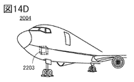
- 14A to 14D are diagrams illustrating an example of a transportation vehicle.
- 15A and 15B are diagrams illustrating a power storage device according to one embodiment of the present invention.
- 16A is a diagram showing an electric bicycle
- FIG. 16B is a diagram showing a secondary battery of the electric bicycle
- FIG. 16C is a diagram explaining an electric motorcycle.
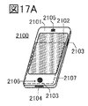
- 17A to 17D are diagrams illustrating examples of electronic devices.
- 18A and 18B are diagrams showing charge-discharge cycle characteristics of a secondary battery at 25°C.
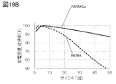
- 19A and 19B are diagrams showing charge-discharge cycle characteristics of a secondary battery at 45°C.
- FIG. 1 shows the order of elements connected by lines. It does not indicate temporal timing between elements that are not directly connected by lines.
- a coprecipitation precursor in which Co, Ni, Mn, or Al is present in one particle is prepared by a coprecipitation method, and after mixing the coprecipitation precursor and Li salt, 2 A process of heating twice and then adding the calcium compound is used.
- a cobalt source 801, a nickel source 802, a manganese source 803, and an aluminum source 804 are prepared, an alkaline solution is prepared as an aqueous solution 893, and a chelating agent is prepared as aqueous solutions 892 and 894.
- Cobalt source 801 , nickel source 802 , manganese source 803 and aluminum source 804 are mixed to prepare aqueous solution 890 .
- a mixed solution 901 is prepared by mixing an aqueous solution 890 and an aqueous solution 892 .
- the mixture 901, the aqueous solution 893, and the aqueous solution 894 are reacted to produce a compound containing at least nickel, cobalt, manganese, and aluminum.
- the reaction may be described as a neutralization reaction, an acid-base reaction, or a co-precipitation reaction, wherein the compound containing at least nickel, cobalt, manganese, and aluminum (nickel compound 805 in FIG. 1) is a nickel-cobalt- It is sometimes described as a precursor of a manganese-aluminum compound.
- nickel compound 805 in FIG. 1 the reaction caused by performing the treatment surrounded by the dashed line in FIG. 1 can also be called a coprecipitation reaction.
- Cobalt aqueous solution used for cobalt source 801 includes cobalt sulfate (eg CoSO 4 ), cobalt chloride (eg CoCl 2 ) or cobalt nitrate (eg Co(NO 3 ) 2 ), cobalt acetate (eg C 4 H 6 CoO 4 ), cobalt Aqueous solutions containing alkoxides, organic cobalt complexes, or hydrates thereof may be mentioned. Further, an organic acid of cobalt such as cobalt acetate, or a hydrate thereof may be used instead of the aqueous solution of cobalt.
- organic acid as used herein includes citric acid, oxalic acid, formic acid, and butyric acid.
- an aqueous solution in which these are dissolved using pure water can be used. Since the cobalt aqueous solution exhibits acidity, it can be described as an acid aqueous solution. Further, the cobalt aqueous solution can be referred to as a cobalt source in the manufacturing process of the positive electrode active material.
- Nickel aqueous solution As the aqueous nickel solution used for the nickel source 802, an aqueous solution of nickel sulfate, nickel chloride, nickel nitrate, or hydrates thereof can be used. Organic acid salts of nickel such as nickel acetate, or aqueous solutions of these hydrates can also be used. Aqueous solutions of nickel alkoxides or organic nickel complexes can also be used.
- ⁇ Manganese aqueous solution As the aqueous manganese solution used for the manganese source 803, manganese salts such as manganese sulfate, manganese chloride, manganese nitrate, or aqueous solutions of these hydrates can be used. Organic acid salts of manganese such as manganese acetate, or aqueous solutions of these hydrates can also be used. Aqueous solutions of manganese alkoxides or organomanganese complexes can also be used.
- aqueous aluminum solution used for the aluminum source 804 an aqueous solution of aluminum sulfate, aluminum chloride, aluminum nitrate, or hydrates thereof can be used. Further, organic acid salts of aluminum such as aluminum acetate, or aqueous solutions of these hydrates can be used. Also, an aqueous solution of an aluminum alkoxide or an organic aluminum complex can be used. [0033]
- the aqueous cobalt solution, nickel aqueous solution, manganese aqueous solution, and aluminum aqueous solution described above may be prepared and then mixed to prepare the aqueous solution 890. For example, nickel sulfate, cobalt sulfate, manganese sulfate, and aluminum sulfate may be mixed. After that, it may be mixed with water to prepare an aqueous solution 890 .
- a mixed solution 901 is prepared by mixing an aqueous solution 890 in which nickel sulfate, cobalt sulfate, manganese sulfate, and aluminum sulfate are mixed with an aqueous solution 892 .
- the aqueous solutions 892 and 894 are aqueous solutions that function as chelating agents, but are not particularly limited and may be pure water.
- Alkaline solutions used for aqueous solution 893 include aqueous solutions containing sodium hydroxide, potassium hydroxide, lithium hydroxide, or ammonia.
- aqueous solutions containing sodium hydroxide, potassium hydroxide, lithium hydroxide, or ammonia For example, an aqueous solution in which these are dissolved using pure water can be used.
- An aqueous solution obtained by dissolving a plurality of kinds selected from sodium hydroxide, potassium hydroxide, and lithium hydroxide in pure water may be used.
- the pH of the reaction system should be 9.0 or more and 12.0 or less, preferably 10.5 or more and 11.5 or less.
- the pH of the aqueous solution in the reaction tank should be maintained within the range of the above conditions. The same applies to the case where the aqueous solution 893 is placed in the reaction tank and the aqueous solution 894 and the mixed liquid 901 are added dropwise.
- the dropping rate of the aqueous solution 893, the aqueous solution 894, or the mixed liquid 901 is preferably 0.1 mL/min or more and 0.8 mL/min or less, which is preferable because the pH condition can be easily controlled.
- the reaction tank has at least a reaction vessel.
- the stirring means has a stirrer or stirring blades. Two to six stirring blades can be provided. For example, when four stirring blades are used, they are preferably arranged in a cross shape when viewed from above.
- the rotation speed of the stirring means is preferably 800 rpm or more and 1200 rpm or less.
- the temperature of the reactor is adjusted to 50°C or higher and 90°C or lower. Dropping of the aqueous solution 893, the aqueous solution 894, or the mixed liquid 901 is preferably started after the temperature is reached.
- the inside of the reaction vessel is preferably an inert atmosphere.
- nitrogen gas should be introduced at a flow rate of 0.5 L/min or more and 2 L/min.
- a reflux condenser allows nitrogen gas to be vented from the reactor and water to be returned to the reactor.
- a compound containing at least nickel, cobalt, manganese, and aluminum precipitates in the reaction vessel after the above reaction.
- Filtration is performed to recover the compounds containing at least nickel, cobalt, manganese, and aluminum.
- the filtered compound containing at least nickel, cobalt, manganese, and aluminum may be further dried. For example, it is dried at 60° C. or higher and 120° C. or lower under vacuum for 0.5 hours or longer and 12 hours or shorter. A compound containing at least nickel, cobalt, manganese and aluminum can thus be obtained.
- the compound containing at least nickel, cobalt, manganese, and aluminum obtained by the above reaction is obtained as secondary particles in which primary particles are aggregated.
- primary particles refer to particles (lumps) of the smallest unit that do not have grain boundaries when observed with a SEM (scanning electron microscope) at a magnification of, for example, 5,000.
- SEM scanning electron microscope
- primary particles refer to the smallest unit particles surrounded by grain boundaries.
- the secondary particles refer to particles (particles independent of others) that are aggregated so that the primary particles share a part of the grain boundary (periphery of the primary particles) and are not easily separated. That is, secondary particles may have grain boundaries.
- Lithium compounds 806 include Li salts such as lithium hydroxide (eg LiOH), lithium carbonate (eg Li 2 CO 3 ), or lithium nitrate (eg LiNO 3 ).
- Li salts such as lithium hydroxide (eg LiOH), lithium carbonate (eg Li 2 CO 3 ), or lithium nitrate (eg LiNO 3 ).
- a material having a low melting point such as lithium hydroxide (melting point 462° C.).
- a positive electrode active material with a high nickel content is more susceptible to cation mixing than lithium cobalt oxide, and thus the first heating 807 needs to be performed at a low temperature. Therefore, it is preferable to use a material with a low melting point.
- the lithium concentration of the positive electrode active material 200A which will be described later, may be appropriately adjusted at this stage.
- a compound containing at least nickel, cobalt, manganese, and aluminum and a lithium compound are mixed to obtain a mixture 904 .
- Mixing uses a mortar or a stirring mixer.
- first heating 807 is performed.
- a baking apparatus for performing the first heating 807 an electric furnace or a rotary kiln furnace can be used.
- the first heating temperature is preferably higher than 400°C and 1050°C or lower. Moreover, the time for the first heating is preferably 1 hour or more and 20 hours or less.
- the secondary particles are crushed or pulverized in a mortar to loosen the agglomeration of the secondary particles, and then collected. Furthermore, it may be classified using a sieve.
- a crucible made of aluminum oxide (also called alumina) with a purity of 99.9% is used.
- the mortar is preferably made of a material that does not easily release impurities. Specifically, it is suitable to use an alumina mortar with a purity of 90% or higher, preferably 99% or higher.
- a second heating 808 is performed.
- a baking apparatus for performing the second heating 808 an electric furnace or a rotary kiln furnace can be used.
- the second heating temperature is preferably higher than 400°C and 1050°C or lower. Moreover, the time for the second heating is preferably 1 hour or more and 20 hours or less.
- the second heating is preferably performed in an oxygen atmosphere, particularly preferably while supplying oxygen. For example, the flow rate is 10 L/min per 1 L of internal volume of the furnace. Further, specifically, the heating is preferably performed while the container containing the mixture 904 is covered.
- the secondary particles are crushed or pulverized in a mortar to loosen the agglomeration of the secondary particles, and then collected. Furthermore, it may be classified using a sieve.
- the obtained mixture 905 is mixed with a compound 910 as a second additive element.
- a compound 910 is used as the second additive element, and a calcium compound is used as the compound 910 .
- Compounds 910 include calcium oxide, calcium carbonate, and calcium hydroxide.
- calcium carbonate (CaCO 3 ) is used as the compound 910 .
- the amount of compound 910 is determined by the practitioner considering the composition of the lithium compound and the compound containing at least nickel, cobalt, manganese, and aluminum. . It is desirable to add calcium by weighing it in the range of 0.5 atomic % or more and 3 atomic % or less with respect to the compound containing nickel, cobalt, manganese and aluminum.
- the third heating 809 is performed.
- the third heating temperature is at least higher than the first heating temperature, preferably higher than 700° C. and 1050° C. or lower.
- the time of the third heating is shorter than that of the second heating, and is preferably 0.5 hours or more and 20 hours or less.
- the third heating is preferably performed in an oxygen atmosphere, particularly preferably while supplying oxygen.
- the flow rate is 10 L/min per 1 L of internal volume of the furnace. Further, specifically, it is preferable to heat the container in which the mixture 905 is put with a lid.
- the secondary particles are crushed or pulverized in a mortar to loosen the agglomeration of the secondary particles, and then collected. Furthermore, it may be classified using a sieve. By including the crushing step, the particle size and/or shape of the positive electrode active material 200A can be made more uniform.
- the positive electrode active material 200A can be produced. Since the positive electrode active material 200A obtained in the above steps is NCM to which Al and Ca are added, it is sometimes called NCMACa.
- Embodiment 2 In this embodiment mode, a coprecipitation apparatus for performing a coprecipitation method in the manufacturing method of Embodiment Mode 1 will be described below.
- the coprecipitation synthesis apparatus 170 shown in FIG. 2 has a reaction vessel 171, and the reaction vessel 171 has a reaction vessel. It is preferable to use a separable flask in the lower part of the reaction vessel and a separable cover in the upper part.
- the separable flask may be cylindrical or round. In the cylindrical type, the separable flask has a flat bottom.
- At least one inlet of the separable cover can be used to control the atmosphere in the reaction vessel 171 .
- the atmosphere preferably comprises nitrogen. In that case, it is preferable to flow nitrogen into the reaction tank 171 . Also, it is preferable to bubble nitrogen through the aqueous solution 192 in the reaction tank 171 .
- the coprecipitation synthesis apparatus 170 may include a reflux condenser connected to at least one inlet of the separable cover, and the reflux condenser discharges atmospheric gas such as nitrogen in the reaction vessel 171. , the water can be returned to the reaction vessel 171 .
- the atmosphere in the reaction vessel 171 may contain an air flow in an amount necessary for discharging the gas generated by the thermal decomposition reaction caused by the heat treatment.
- an aqueous solution 894 (chelating agent) is placed in the reaction bath 171 , and then the mixture 901 and the aqueous solution 893 (alkaline solution) are dropped into the reaction bath 171 .
- the aqueous solution 192 in FIG. 2 shows the state in which dripping is started.
- the aqueous solution 894 may be referred to as a charging solution.
- the charging solution may be referred to as an adjustment solution, and may refer to an aqueous solution before reaction, that is, an aqueous solution in an initial state.
- the coprecipitation synthesis apparatus 170 includes a stirring unit 172, a stirring motor 173, a thermometer 174, a tank 175, a pipe 176, a pump 177, a tank 180, a pipe 181, a pump 182, a tank 186, a pipe 187, a pump 188, and a controller. 190.
- the stirring section 172 can stir the aqueous solution 192 in the reaction vessel 171 and has a stirring motor 173 as a power source for rotating the stirring section 172 .
- the stirring unit 172 has paddle-type stirring blades (referred to as paddle blades), and the paddle blades have two or more and six or less blades, and the blades have an inclination of 40 degrees or more and 70 degrees or less. may be
- thermometer 174 can measure the temperature of the aqueous solution 192 .
- the temperature of the reaction vessel 171 can be controlled using a thermoelectric element so that the temperature of the aqueous solution 192 remains constant.
- Thermoelectric elements include, for example, Peltier elements.
- a pH meter (not shown) is also arranged in the reaction tank 171 to measure the pH of the aqueous solution 192 .
- Each tank can store a different raw material aqueous solution.
- each tank can be filled with mixed liquid 901 and aqueous solution 893 .
- a tank filled with an aqueous solution 894 may be provided to serve as a charging solution.
- Each tank is provided with a pump, and the raw material aqueous solution can be dripped into the reaction vessel 171 through the pipe by using the pump.
- Each pump can control the dropping amount of the raw material aqueous solution, that is, the liquid feeding amount.
- a valve may be provided in the tube 176 to control the dropping amount of the raw material aqueous solution, that is, the liquid feeding amount.
- the control device 190 is electrically connected to the stirring motor 173, the thermometer 174, the pumps 177, 182, and 188, and controls the rotation speed of the stirring section 172, the temperature of the aqueous solution 192, and the dropping amount of each raw material aqueous solution. can be controlled.
- the number of rotations of the stirring section 172 may be, for example, 800 rpm or more and 1200 rpm or less. Further, the stirring may be performed while the aqueous solution 192 is heated to 50° C. or higher and 90° C. or lower. At that time, the mixture 901 may be dropped into the reaction tank 171 at a constant rate.
- the number of rotations of the paddle blades is not limited to a constant value, and can be adjusted as appropriate. For example, it is possible to change the rotation speed according to the amount of liquid in the reaction tank 171 . Furthermore, the dropping speed of the mixed liquid 901 can also be adjusted.
- the dropping speed may be controlled so that the mixed liquid 901 is dropped and the aqueous solution 892 is dropped when the pH value is changed from the desired value.
- the above pH value is 9.0 or more and 11.0 or less, preferably 10.0 or more and 10.5 or less.
- reaction product precipitates in the reaction tank 171 through the above steps.
- the reaction product has compounds containing at least nickel, cobalt, manganese and aluminum.
- the reaction may be referred to as co-precipitation or co-precipitation, and the process may be referred to as the co-precipitation process.
- FIG. 3A is an exploded perspective view of a coin-type (single-layer flat type) secondary battery
- FIG. 3B is an external view
- FIG. 3C is a cross-sectional view thereof.
- Coin-type secondary batteries are mainly used in small electronic devices.
- coin cell batteries include button cells.
- FIG. 3A for the sake of clarity, a schematic diagram is used so that the overlapping of members (vertical relationship and positional relationship) can be understood. Therefore, FIG. 3A and FIG. 3B do not correspond to each other completely.
- positive electrode 304, separator 310, negative electrode 307, spacer 322, and washer 312 are stacked. These are sealed with a negative electrode can 302 and a positive electrode can 301 .
- a gasket for sealing is not shown in FIG. 3A.
- the spacer 322 and the washer 312 are used to protect the inside or fix the position inside the can when the positive electrode can 301 and the negative electrode can 302 are pressure-bonded. Spacers 322 and washers 312 are made of stainless steel or an insulating material.
- a positive electrode 304 has a laminated structure in which a positive electrode active material layer 306 is formed on a positive electrode current collector 305 .
- a separator 310 and a ring-shaped insulator 313 are arranged so as to cover the side and top surfaces of the positive electrode 304, respectively.
- the separator 310 has a larger planar area than the positive electrode 304 .
- FIG. 3B is a perspective view of a completed coin-type secondary battery.
- a positive electrode can 301 which also serves as a positive electrode terminal
- a negative electrode can 302 which also serves as a negative electrode terminal
- the positive electrode 304 is formed of a positive electrode current collector 305 and a positive electrode active material layer 306 provided so as to be in contact therewith.
- the negative electrode 307 is formed of a negative electrode current collector 308 and a negative electrode active material layer 309 provided so as to be in contact therewith.
- the negative electrode 307 is not limited to a laminated structure, and may be a lithium metal foil or a lithium-aluminum alloy foil.
- the active material layers of the positive electrode 304 and the negative electrode 307 used in the coin-type secondary battery 300 may be formed only on one side.
- the positive electrode can 301 and the negative electrode can 302 are made of metals such as nickel, aluminum, and titanium, which are corrosion-resistant to the liquid electrolyte, alloys thereof, and alloys thereof with other metals (for example, stainless steel). can be used. Also, nickel and aluminum are preferably coated to prevent corrosion by the liquid electrolyte.
- the positive electrode can 301 and the negative electrode can 302 are electrically connected to the positive electrode 304 and the negative electrode 307, respectively.
- negative electrode 307, positive electrode 304 and separator 310 are immersed in a liquid electrolyte, and as shown in FIG.
- the positive electrode can 301 and the negative electrode can 302 are pressure-bonded via a gasket 303 to manufacture a coin-shaped secondary battery 300 .
- the coin-shaped secondary battery 300 can have high capacity, high charge/discharge capacity, and excellent cycle characteristics. Note that in the case of a secondary battery having a solid electrolyte layer between the negative electrode 307 and the positive electrode 304, the separator 310 may be omitted.
- a cylindrical secondary battery 616 has a positive electrode cap (battery lid) 601 on its top surface and battery cans (armor cans) 602 on its side and bottom surfaces.
- the positive electrode cap 601 and the battery can (outer can) 602 are insulated by a gasket (insulating packing) 610 .
- FIG. 4B is a diagram schematically showing a cross section of a cylindrical secondary battery.
- the cylindrical secondary battery shown in FIG. 4B has a positive electrode cap (battery cover) 601 on the top surface and battery cans (armor cans) 602 on the side and bottom surfaces.
- the positive electrode cap and the battery can (outer can) 602 are insulated by a gasket (insulating packing) 610 .
- a battery element in which a strip-shaped positive electrode 604 and a strip-shaped negative electrode 606 are wound with a separator 605 interposed therebetween is provided inside a hollow columnar battery can 602 .
- the battery element is wound around the central axis.
- Battery can 602 is closed at one end and open at the other end.
- the battery can 602 can be made of nickel, aluminum, titanium metals, alloys thereof, and alloys of these with other metals (eg, stainless steel) that are resistant to corrosion in liquid electrolytes. can.
- the battery element in which the positive electrode, the negative electrode and the separator are wound is sandwiched between a pair of insulating plates 608 and 609 facing each other.
- a non-aqueous electrolyte (not shown) is filled inside the battery can 602 in which the battery element is provided. The same non-aqueous electrolyte as used in coin-type secondary batteries can be used.
- FIGS. 4A to 4D illustrate the secondary battery 616 in which the height of the cylinder is greater than the diameter of the cylinder, but the invention is not limited to this.
- the diameter of the cylinder may be a secondary battery that is larger than the height of the cylinder. With such a configuration, for example, the size of the secondary battery can be reduced.
- the cylindrical secondary battery 616 With using the positive electrode active material 200A described in Embodiment 1 for the positive electrode 604, the cylindrical secondary battery 616 with high capacity, high charge/discharge capacity, and excellent cycle characteristics can be obtained.
- a positive electrode terminal (positive collector lead) 603 is connected to the positive electrode 604
- a negative electrode terminal (negative collector lead) 607 is connected to the negative electrode 606 .
- Both the positive electrode terminal 603 and the negative electrode terminal 607 can use a metal material such as aluminum.
- the positive electrode terminal 603 and the negative electrode terminal 607 are resistance welded to the safety valve mechanism 613 and the bottom of the battery can 602, respectively.
- the safety valve mechanism 613 is electrically connected to the positive electrode cap 601 via a PTC (Positive Temperature Coefficient) element 611 .
- the safety valve mechanism 613 disconnects the electrical connection between the positive electrode cap 601 and the positive electrode 604 when the increase in internal pressure of the battery exceeds a predetermined threshold.
- the PTC element 611 is a thermal resistance element whose resistance increases when the temperature rises, and the increase in resistance limits the amount of current to prevent abnormal heat generation.
- Barium titanate (BaTiO 3 ) based semiconductor ceramics can be used for the PTC element.
- FIG. 4C shows an example of power storage system 615 .
- a power storage system 615 includes a plurality of secondary batteries 616 .
- the positive electrode of each secondary battery contacts and is electrically connected to a conductor 624 separated by an insulator 625 .
- Conductor 624 is electrically connected to control circuit 620 via wiring 623 .
- a negative electrode of each secondary battery is electrically connected to the control circuit 620 through a wiring 626 .
- a protection circuit that prevents overcharge or overdischarge can be applied as the control circuit 620 .
- FIG. 4D shows an example of an electrical storage system 615 .
- a power storage system 615 includes a plurality of secondary batteries 616 that are sandwiched between a conductive plate 628 and a conductive plate 614 .
- the plurality of secondary batteries 616 are electrically connected to the conductive plates 628 and 614 by wirings 627 .
- the plurality of secondary batteries 616 may be connected in parallel, may be connected in series, or may be connected in series after being connected in parallel.
- a plurality of secondary batteries 616 may be connected in series after being connected in parallel.
- a temperature control device may be provided between the secondary batteries 616 .
- the secondary battery 616 When the secondary battery 616 is overheated, it can be cooled by the temperature control device, and when the secondary battery 616 is too cold, it can be heated by the temperature control device. Therefore, the performance of power storage system 615 is less likely to be affected by the outside air temperature.
- the power storage system 615 is electrically connected to the control circuit 620 via wiring 621 and wiring 622 .
- the wiring 621 is electrically connected to the positive electrodes of the plurality of secondary batteries 616 through the conductive plate 628
- the wiring 622 is electrically connected to the negative electrodes of the plurality of secondary batteries 616 through the conductive plate 614 .
- FIG. 5 A structural example of the secondary battery will be described with reference to FIGS. 5 and 6.
- FIG. 5 A structural example of the secondary battery will be described with reference to FIGS. 5 and 6.
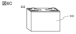
- a secondary battery 913 illustrated in FIG. 5A includes a wound body 950 provided with a terminal 951 and a terminal 952 inside a housing 930 .
- the wound body 950 is immersed in the liquid electrolyte inside the housing 930 .
- the terminal 952 is in contact with the housing 930, and the terminal 951 is not in contact with the housing 930 by using an insulating material.
- the housing 930 is shown separately for the sake of convenience. exist.
- a metal material for example, aluminum
- a resin material can be used as the housing 930 .
- the housing 930 shown in FIG. 5A may be made of a plurality of materials.
- a housing 930a and a housing 930b are bonded together, and a wound body 950 is provided in a region surrounded by the housings 930a and 930b.
- An insulating material such as an organic resin can be used for the housing 930a.
- shielding of the electric field by the secondary battery 913 can be suppressed by using an organic resin for the surface on which the antenna is formed.
- an antenna may be provided inside the housing 930a.
- a metal material, for example, can be used as the housing 930b.
- a wound body 950 has a negative electrode 931 , a positive electrode 932 , and a separator 933 .
- the wound body 950 is a wound body in which the negative electrode 931 and the positive electrode 932 are laminated with the separator 933 interposed therebetween, and the laminated sheet is wound. Note that the negative electrode 931, the positive electrode 932, and the separator 933 may be stacked more than once.
- the secondary battery 913 may have a wound body 950a as shown in FIGS. 6A to 6C.
- a wound body 950 a illustrated in FIG. 6A includes a negative electrode 931 , a positive electrode 932 , and a separator 933 .
- the negative electrode 931 has a negative electrode active material layer 931a.
- the positive electrode 932 has a positive electrode active material layer 932a.
- the secondary battery 913 can have high capacity, high charge/discharge capacity, and excellent cycle characteristics.
- the separator 933 has a wider width than the negative electrode active material layer 931a and the positive electrode active material layer 932a, and is wound so as to overlap with the negative electrode active material layer 931a and the positive electrode active material layer 932a.
- the width of the negative electrode active material layer 931a is wider than that of the positive electrode active material layer 932a.
- the wound body 950a having such a shape is preferable because of its good safety and productivity.
- negative electrode 931 is electrically connected to terminal 951 .
- Terminal 951 is electrically connected to terminal 911a.
- the positive electrode 932 is electrically connected to the terminal 952 .
- Terminal 952 is electrically connected to terminal 911b.
- the casing 930 covers the wound body 950 a and the liquid electrolyte to form the secondary battery 913 .
- the housing 930 is preferably provided with a safety valve and an overcurrent protection element.
- the safety valve is a valve that opens the interior of housing 930 at a predetermined internal pressure in order to prevent battery explosion.
- the secondary battery 913 may have multiple wound bodies 950a. By using a plurality of wound bodies 950a, the secondary battery 913 with higher charge/discharge capacity can be obtained.
- the description of the secondary battery 913 illustrated in FIGS. 5A to 5C can be referred to for other elements of the secondary battery 913 illustrated in FIGS. 6A and 6B.
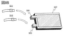
- FIGS. 7A and 7B show an example of an external view of an example of a laminated secondary battery.
- 7A and 7B have a positive electrode 503, a negative electrode 506, a separator 507, an outer package 509, a positive electrode lead electrode 510 and a negative electrode lead electrode 511.
- FIG. 7A and 7B have a positive electrode 503, a negative electrode 506, a separator 507, an outer package 509, a positive electrode lead electrode 510 and a negative electrode lead electrode 511.
- FIG. 8A shows an external view of the positive electrode 503 and the negative electrode 506.
- the positive electrode 503 has a positive electrode current collector 501 , and the positive electrode active material layer 502 is formed on the surface of the positive electrode current collector 501 .
- the positive electrode 503 has a region where the positive electrode current collector 501 is partially exposed (hereinafter referred to as a tab region).
- the negative electrode 506 has a negative electrode current collector 504 , and the negative electrode active material layer 505 is formed on the surface of the negative electrode current collector 504 .
- the negative electrode 506 has a region where the negative electrode current collector 504 is partially exposed, that is, a tab region.
- the area and shape of the tab regions of the positive and negative electrodes are not limited to the example shown in FIG. 8A.
- FIG. 8B shows the negative electrode 506, separator 507 and positive electrode 503 stacked.
- an example is shown in which five sets of negative electrodes and four sets of positive electrodes are used. It can also be called a laminate consisting of a negative electrode, a separator, and a positive electrode.
- the tab regions of the positive electrode 503 are joined together, and the positive electrode lead electrode 510 is joined to the tab region of the outermost positive electrode.
- ultrasonic welding may be used.
- bonding between the tab regions of the negative electrode 506 and bonding of the negative electrode lead electrode 511 to the tab region of the outermost negative electrode are performed.
- the negative electrode 506 , the separator 507 , and the positive electrode 503 are arranged over the exterior body 509 .
- the exterior body 509 is folded at the portion indicated by the dashed line. After that, the outer peripheral portion of the exterior body 509 is joined. Thermocompression bonding, for example, may be used for bonding. At this time, a region (hereinafter referred to as an introduction port) that is not joined is provided in a part (or one side) of the exterior body 509 so that a liquid electrolyte can be introduced later.
- an introduction port a region that is not joined is provided in a part (or one side) of the exterior body 509 so that a liquid electrolyte can be introduced later.
- a liquid electrolyte (not shown) is introduced into the exterior body 509 through an inlet provided in the exterior body 509 . It is preferable to introduce the liquid electrolyte under a reduced pressure atmosphere or an inert atmosphere. And finally, the inlet is joined. In this manner, a laminated secondary battery 500 can be manufactured.
- the secondary battery 500 can have high capacity, high charge/discharge capacity, and excellent cycle characteristics.
- Battery pack example An example of a secondary battery pack of one embodiment of the present invention that can be wirelessly charged using an antenna will be described with reference to FIGS. 9A to 9C.
- FIG. 9A is a diagram showing the appearance of the secondary battery pack 531, which has a thin rectangular parallelepiped shape (also called a thick flat plate shape).
- FIG. 9B is a diagram illustrating the configuration of the secondary battery pack 531.
- the secondary battery pack 531 has a circuit board 540 and a secondary battery 513 .
- a label 529 is attached to the secondary battery 513 .
- Circuit board 540 is secured by seal 515 .
- the secondary battery pack 531 has an antenna 517 .
- the inside of the secondary battery 513 may have a structure having a wound body or a structure having a laminated body.
- the secondary battery pack 531 has a control circuit 590 on a circuit board 540 as shown in FIG. 9B. Also, the circuit board 540 is electrically connected to the terminals 514 . In addition, the circuit board 540 is electrically connected to the antenna 517 , one of the positive and negative leads 551 and the other of the positive and negative leads 552 of the secondary battery 513 .
- FIG. 9C it may have a circuit system 590a provided on circuit board 540 and a circuit system 590b electrically connected to circuit board 540 via terminals 514.
- FIG. 9C it may have a circuit system 590a provided on circuit board 540 and a circuit system 590b electrically connected to circuit board 540 via terminals 514.
- antenna 517 is not limited to a coil shape, and may have a linear shape or a plate shape, for example. Also, a planar antenna, an aperture antenna, a traveling wave antenna, an EH antenna, a magnetic field antenna, or a dielectric antenna may be used. Alternatively, antenna 517 may be a planar conductor. This flat conductor can function as one of conductors for electric field coupling. That is, the antenna 517 may function as one of the two conductors of the capacitor. As a result, electric power can be exchanged not only by electromagnetic fields and magnetic fields, but also by electric fields.
- Secondary battery pack 531 has layer 519 between antenna 517 and secondary battery 513 .
- the layer 519 has a function of shielding an electromagnetic field generated by the secondary battery 513, for example.
- a magnetic material for example, can be used as the layer 519 .
- a secondary battery 400 of one embodiment of the present invention includes a positive electrode 410, a solid electrolyte layer 420, and a negative electrode 430.
- the positive electrode 410 has a positive electrode current collector 413 and a positive electrode active material layer 414 .
- a positive electrode active material layer 414 includes a positive electrode active material 411 and a solid electrolyte 421 .
- the positive electrode active material 200A described in Embodiment 1 is used as the positive electrode active material 411 . Further, the positive electrode active material layer 414 may contain a conductive aid and a binder.
- Solid electrolyte layer 420 has solid electrolyte 421 .
- Solid electrolyte layer 420 is a region located between positive electrode 410 and negative electrode 430 and having neither positive electrode active material 411 nor negative electrode active material 431 .
- the negative electrode 430 has a negative electrode current collector 433 and a negative electrode active material layer 434 .
- a negative electrode active material layer 434 includes a negative electrode active material 431 and a solid electrolyte 421 . Further, the negative electrode active material layer 434 may contain a conductive aid and a binder. Note that when metal lithium is used as the negative electrode active material 431, particles do not need to be formed, and thus the negative electrode 430 without the solid electrolyte 421 can be formed as shown in FIG. 10B.
- FIG. 10B shows an example in which the negative electrode active material 431 is formed using a sputtering method. It is preferable to use metallic lithium for the negative electrode 430 because the energy density of the secondary battery 400 can be improved.
- solid electrolyte 421 included in the solid electrolyte layer 420 for example, a sulfide-based solid electrolyte, an oxide-based solid electrolyte, or a halide-based solid electrolyte can be used.
- Sulfide-based solid electrolytes include thiolysicone-based (Li 10 GeP 2 S 12 , Li 3.25 Ge 0.25 P 0.75 S 4 ), sulfide glass (70Li 2 S, 30P 2 S 5 , 30Li 2 S ⁇ 26B 2 S 3 ⁇ 44LiI, 63Li 2 S ⁇ 36SiS 2 ⁇ 1Li 3 PO 4 , 57Li 2 S ⁇ 38SiS 2 ⁇ 5Li 4 SiO 4 , 50Li 2 S ⁇ 50GeS 2 ), sulfide crystallized glass (Li 7 P 3 S 11 , Li 3.25 P 0.95 S 4 ).
- Sulfide-based solid electrolytes have the advantages that they include materials with high conductivity, can be synthesized at low temperatures, and are relatively soft, so that conductive paths are easily maintained even after charging and discharging.
- the oxide-based solid electrolyte includes a material having a perovskite crystal structure (La2 /3- xLi3xTiO3 ) , a material having a NASICON crystal structure (Li1- YAlYTi2-Y ( PO4 ) 3 ), a material having a garnet - type crystal structure ( Li7La3Zr2O12 ), a material having a LISICON - type crystal structure ( Li14ZnGe4O16 ) , LLZO ( Li7La3Zr2O12 ), oxidation material glass ( Li3PO4 - Li4SiO4 , 50Li4SiO4.50Li3BO3 ) , oxide crystallized glass ( Li1.07Al0.69Ti1.46 ( PO4 ) 3 , Li1 .5 Al 0.5 Ge 1.5 (PO 4 ) 3 ). Oxide-based solid electrolytes have the advantage of being stable in the atmosphere.
- Halide-based solid electrolytes include LiAlCl 4 , Li 3 InBr 6 , LiF, LiCl, LiBr and LiI. Composite materials in which pores of porous aluminum oxide or porous silica are filled with these halide-based solid electrolytes can also be used as solid electrolytes.
- Li1 + xAlxTi2 -x ( PO4) 3 ( 0[x[1) (hereinafter referred to as LATP) having a NASICON-type crystal structure is aluminum and titanium in the secondary battery 400 of one embodiment of the present invention. Since it contains an element that may be contained in the positive electrode active material used in , a synergistic effect can be expected for improving cycle characteristics, which is preferable. Also, an improvement in productivity can be expected by reducing the number of processes.
- the NASICON - type crystal structure is a compound represented by M 2 (XO 4 ) 3 (M: transition metal, X: S, P, As, Mo, or W). It has a structure in which a tetrahedron and an XO 4 tetrahedron share a vertex and are arranged three-dimensionally.
- Exterior body and shape of secondary battery Various materials and shapes can be used for the exterior body of the secondary battery 400 of one embodiment of the present invention, but it preferably has a function of pressurizing the positive electrode, the solid electrolyte layer, and the negative electrode.
- FIG. 11 is an example of a cell for evaluating materials for an all-solid-state battery.
- FIG. 11A is a schematic cross-sectional view of the evaluation cell.
- the evaluation cell has a lower member 761, an upper member 762, and a fixing screw or wing nut 764 for fixing them.
- a plate 753 is pressed to secure the evaluation material.
- An insulator 766 is provided between a lower member 761 made of stainless steel and an upper member 762 .
- An O-ring 765 is provided between the upper member 762 and the set screw 763 for sealing.
- the evaluation material is placed on an electrode plate 751, surrounded by an insulating tube 752, and pressed from above by an electrode plate 753. As shown in FIG. FIG. 11B is an enlarged perspective view of the periphery of this evaluation material.
- FIG. 11C As an evaluation material, an example of lamination of a positive electrode 750a, a solid electrolyte layer 750b, and a negative electrode 750c is shown, and a cross-sectional view thereof is shown in FIG. 11C. The same symbols are used for the same portions in FIGS. 11A to 11C.
- the electrode plate 751 and the lower member 761 electrically connected to the positive electrode 750a correspond to a positive electrode terminal. It can be said that the electrode plate 753 and the upper member 762 electrically connected to the negative electrode 750c correspond to a negative electrode terminal.
- the electrical resistance can be measured while pressing the evaluation material through the electrode plate 751 and the electrode plate 753 .
- a highly airtight package is preferably used for the exterior body of the secondary battery of one embodiment of the present invention.
- a ceramic package or resin package can be used.
- FIG. 12A shows a perspective view of a secondary battery of one embodiment of the present invention having an exterior body and a shape different from those in FIG.
- the secondary battery of FIG. 12A has external electrodes 771 and 772 and is sealed with an exterior body having a plurality of package members.
- FIG. 12B shows an example of a cross section taken along the dashed line in FIG. 12A.
- a laminate having a positive electrode 750a, a solid electrolyte layer 750b, and a negative electrode 750c includes a package member 770a in which an electrode layer 773a is provided on a flat plate, a frame-shaped package member 770b, and a package member 770c in which an electrode layer 773b is provided on a flat plate. , and has a sealed structure.
- the package members 770a, 770b, 770c can be made of insulating materials such as resin materials and ceramics.
- the external electrode 771 is electrically connected to the positive electrode 750a through the electrode layer 773a and functions as a positive electrode terminal.
- the external electrode 772 is electrically connected to the negative electrode 750c through the electrode layer 773b and functions as a negative electrode terminal.
- FIG. 13C shows an example of application to an electric vehicle (EV).
- EV electric vehicle
- the electric vehicle is provided with first batteries 1301a and 1301b as secondary batteries for main driving, and a second battery 1311 that supplies power to an inverter 1312 that starts the motor 1304 .
- the second battery 1311 is also called cranking battery (also called starter battery).
- the second battery 1311 only needs to have a high output and does not need a large capacity so much, and the capacity of the second battery 1311 is smaller than that of the first batteries 1301a and 1301b.
- the internal structure of the first battery 1301a may be the wound type shown in FIG. 5A or 6C, or the laminated type shown in FIG. 7A or 7B. Further, the all-solid-state battery of Embodiment 4 may be used as the first battery 1301a. By using the all-solid-state battery of Embodiment 4 for the first battery 1301a, the capacity can be increased, the safety can be improved, and the size and weight can be reduced.
- This embodiment mode shows an example in which two first batteries 1301a and 1301b are connected in parallel, but three or more batteries may be connected in parallel. Further, if the first battery 1301a can store sufficient electric power, the first battery 1301b may be omitted. A large amount of electric power can be extracted by forming a battery pack including a plurality of secondary batteries. A plurality of secondary batteries may be connected in parallel, may be connected in series, or may be connected in series after being connected in parallel. A plurality of secondary batteries is also called an assembled battery.
- a secondary battery for vehicle has a service plug or a circuit breaker that can cut off high voltage without using a tool in order to cut off power from a plurality of secondary batteries.
- the power of the first batteries 1301a and 1301b is mainly used to rotate the motor 1304, but is supplied to the 42V in-vehicle components (electric power steering 1307, heater 1308, defogger 1309) via the DCDC circuit 1306. supply power.
- the first battery 1301a is also used to rotate the rear motor 1317 when the rear wheel has the rear motor 1317 .
- the second battery 1311 supplies power to 14V in-vehicle components (audio 1313, power window 1314, lamps 1315) through the DCDC circuit 1310.
- FIG. 14V in-vehicle components audio 1313, power window 1314, lamps 1315.
- the first battery 1301a will be described with reference to FIG. 13A.
- FIG. 13A shows an example in which nine prismatic secondary batteries 1300 are used as one battery pack 1415 .
- Nine square secondary batteries 1300 are connected in series, one electrode is fixed by a fixing portion 1413 made of an insulator, and the other electrode is fixed by a fixing portion 1414 made of an insulator.
- an example of fixing by fixing portions 1413 and 1414 is shown; Since it is assumed that the vehicle is subject to vibration or shaking from the outside (road surface), it is preferable to fix a plurality of secondary batteries with the fixing portions 1413 and 1414 and the battery housing box.
- One electrode is electrically connected to the control circuit portion 1320 through a wiring 1421 .
- the other electrode is electrically connected to the control circuit section 1320 by wiring 1422 .
- FIG. 13B shows an example of a block diagram of the battery pack 1415 shown in FIG. 13A.
- the control circuit unit 1320 includes a switch unit 1324 including at least a switch for preventing overcharge and a switch for preventing overdischarge, a control circuit 1322 for controlling the switch unit 1324, a voltage measurement unit for the first battery 1301a, have
- the control circuit unit 1320 is set with upper and lower voltage limits of the secondary battery to be used, and limits the upper limit of the current from the outside and the upper limit of the output current to the outside. The range from the lower limit voltage to the upper limit voltage of the secondary battery is within the voltage range recommended for use.
- the control circuit section 1320 controls the switch section 1324 to prevent over-discharging and over-charging, it can also be called a protection circuit.
- control circuit 1322 detects a voltage that is likely to cause overcharging
- the switch of the switch section 1324 is turned off to cut off the current.
- a PTC element may be provided in the charging/discharging path to provide a function of interrupting the current according to the temperature rise.
- the control circuit section 1320 also has an external terminal 1325 (+IN) and an external terminal 1326 (-IN).
- the switch portion 1324 can be configured by combining an n-channel transistor and a p-channel transistor.
- the switch unit 1324 is not limited to a switch having a Si transistor using single crystal silicon. indium), SiC (silicon carbide), ZnSe (zinc selenide), GaN (gallium nitride), and GaOx (gallium oxide; x is a real number greater than 0).
- the first batteries 1301a and 1301b mainly supply power to 42V system (high voltage system) in-vehicle equipment, and the second battery 1311 supplies power to 14V system (low voltage system) in-vehicle equipment.
- the second battery 1311 is often adopted as a lead-acid battery because of its cost advantage.
- the second battery 1311 may use a lead-acid battery, an all-solid battery, or an electric double layer capacitor.
- the all-solid-state battery of Embodiment 4 may be used.
- Regenerative energy generated by the rotation of tire 1316 is sent to motor 1304 via gear 1305 and charged to second battery 1311 via control circuit section 1321 from motor controller 1303 and battery controller 1302 .
- the battery controller 1302 charges the first battery 1301 a through the control circuit unit 1320 .
- the battery controller 1302 charges the first battery 1301 b through the control circuit unit 1320 . In order to efficiently charge the regenerated energy, it is desirable that the first batteries 1301a and 1301b be capable of rapid charging.
- the battery controller 1302 can set the charging voltage and charging current of the first batteries 1301a, 1301b.
- the battery controller 1302 can set charging conditions according to the charging characteristics of the secondary battery to be used and perform rapid charging.
- the outlet of the charger or the connection cable of the charger is electrically connected to the battery controller 1302 .
- Electric power supplied from an external charger charges the first batteries 1301 a and 1301 b via the battery controller 1302 .
- Some chargers are provided with a control circuit and do not use the function of the battery controller 1302. In order to prevent overcharging, the first batteries 1301a and 1301b are charged via the control circuit unit 1320. is preferred.
- the connection cable or the connection cable of the charger is provided with the control circuit.
- the control circuit section 1320 is sometimes called an ECU (Electronic Control Unit).
- the ECU is connected to a CAN (Controller Area Network) provided in the electric vehicle.
- CAN is one of serial communication standards used as an in-vehicle LAN.
- the ECU includes a microcomputer.
- the ECU uses a CPU or a GPU.
- External chargers installed at charging stations include 100V outlet, 200V outlet, 3-phase 200V and 50kW.
- the battery can be charged by receiving power supply from an external charging facility by a non-contact power supply method.
- the secondary battery of the present embodiment described above uses the positive electrode active material 200A described in the first embodiment. Furthermore, by using graphene as a conductive agent, even if the electrode layer is thickened and the amount supported is increased, the decrease in capacity can be suppressed and the high capacity can be maintained. realizable. To provide a vehicle which is effective especially for a secondary battery used in a vehicle and has a long cruising distance, specifically, a traveling distance of 500 km or more per charge without increasing the weight ratio of the secondary battery to the total weight of the vehicle. be able to.
- the secondary battery of the present embodiment described above can increase the operating voltage of the secondary battery by using the positive electrode active material 200A described in Embodiment 1, and can be used as the charging voltage increases. Capacity can be increased.
- the positive electrode active material 200A described in Embodiment 1 for the positive electrode it is possible to provide a vehicle secondary battery having excellent cycle characteristics.
- the secondary battery shown in any one of FIGS. 4D, 6C, and 13A when the secondary battery shown in any one of FIGS. 4D, 6C, and 13A is installed in a vehicle, the next-generation clean of a hybrid vehicle (HV), an electric vehicle (EV), or a plug-in hybrid vehicle (PHV) can be used.
- An energy vehicle can be realized.
- a secondary battery can also be mounted on a transport vehicle for an explorer or a spacecraft.
- the secondary battery of one embodiment of the present invention can be a high-capacity secondary battery. Therefore, the secondary battery of one embodiment of the present invention is suitable for miniaturization and weight reduction, and can be suitably used for transportation vehicles.
- a vehicle 2001 shown in FIG. 14A is an electric vehicle that uses an electric motor as a power source for running. Alternatively, it is a hybrid vehicle in which an electric motor and an engine can be appropriately selected and used as power sources for running.
- a secondary battery is mounted in a vehicle, an example of the secondary battery described in Embodiment 3 is installed at one or more places.
- a car 2001 shown in FIG. 14A has a battery pack 2200, and the battery pack has a secondary battery module to which a plurality of secondary batteries are connected. Furthermore, it is preferable to have a charging control device electrically connected to the secondary battery module.
- the vehicle 2001 can charge the secondary battery of the vehicle 2001 by receiving power from an external charging facility by a plug-in system and a non-contact power supply system.
- the charging method and the standard of the connector may appropriately be a predetermined method represented by CHAdeMO (registered trademark) or Combo.
- the secondary battery may be a charging station provided in a commercial facility, or may be a household power source.
- plug-in technology can charge a power storage device mounted on the automobile 2001 by power supply from the outside. Charging can be performed by converting AC power into DC power through a conversion device of an ACDC converter.
- the power receiving device can be mounted on a vehicle, and power can be supplied from a power transmission device on the ground in a non-contact manner for charging.
- this non-contact power supply system it is possible to charge the vehicle not only while the vehicle is stopped but also while the vehicle is running by installing a power transmission device on the road or the outer wall.
- power may be transmitted and received between two vehicles.
- a solar battery may be provided on the exterior of the vehicle, and the secondary battery may be charged while the vehicle is stopped and while the vehicle is running.
- An electromagnetic induction method or a magnetic resonance method can be used for such contactless power supply.
- FIG. 14B shows a large transport vehicle 2002 with electrically controlled motors as an example of a transport vehicle.
- the secondary battery module of the transportation vehicle 2002 has a maximum voltage of 170 V, for example, a four-cell unit of secondary batteries having a nominal voltage of 3.0 V or more and 5.0 V or less, and 48 cells connected in series. Except for the number of secondary batteries forming the secondary battery module of the battery pack 2201, the function is the same as that of FIG. 14A, so the explanation is omitted.
- FIG. 14C shows, as an example, a large transport vehicle 2003 with electrically controlled motors.
- the secondary battery module of the transportation vehicle 2003 has a maximum voltage of 600 V, for example, a hundred or more secondary batteries with a nominal voltage of 3.0 V or more and 5.0 V or less connected in series.
- a secondary battery using positive electrode active material 200A shown in Embodiment 1 as a positive electrode a secondary battery with excellent rate characteristics and charge/discharge cycle characteristics can be manufactured, and the performance of transportation vehicle 2003 can be improved. And it can contribute to longer life.
- 14A except that the number of secondary batteries forming the secondary battery module of the battery pack 2202 is different, the description is omitted.
- FIG. 14D shows an aircraft 2004 having an engine that burns fuel as an example. Since the aircraft 2004 shown in FIG. 14D has wheels for takeoff and landing, it can be said to be a part of a transportation vehicle, and a secondary battery module is configured by connecting a plurality of secondary batteries, and the secondary battery module and the charging device are charged. It has a battery pack 2203 including a controller.
- the secondary battery module of the aircraft 2004 has a maximum voltage of 32V, for example, eight 4V secondary batteries connected in series. Except for the number of secondary batteries forming the secondary battery module of the battery pack 2203, the function is the same as that of FIG. 14A, so the explanation is omitted.
- a house illustrated in FIG. 15A includes a power storage device 2612 including a secondary battery that is one embodiment of the present invention and a solar panel 2610 .
- the power storage device 2612 is electrically connected to the solar panel 2610 through wiring 2611 .
- the power storage device 2612 and the ground-mounted charging device 2604 may be electrically connected.
- a power storage device 2612 can be charged with power obtained from the solar panel 2610 .
- Electric power stored in power storage device 2612 can be used to charge a secondary battery of vehicle 2603 via charging device 2604 .
- Power storage device 2612 is preferably installed in the underfloor space. By installing in the space under the floor, the space above the floor can be effectively used. Alternatively, power storage device 2612 may be installed on the floor.
- the power stored in the power storage device 2612 can also supply power to other electronic devices in the house. Therefore, the use of the power storage device 2612 according to one embodiment of the present invention as an uninterruptible power supply makes it possible to use the electronic device even when power cannot be supplied from a commercial power supply due to a power failure.
- FIG. 15B illustrates an example of a power storage device according to one embodiment of the present invention.
- a power storage device 791 according to one embodiment of the present invention is installed in an underfloor space 796 of a building 799.
- the power storage device 791 may be provided with the control circuit described in Embodiment 5, and a secondary battery whose positive electrode is the positive electrode active material 200A described in Embodiment 1 can be used for the power storage device 791 to have a long service life.
- a power storage device 791 can be used.
- a control device 790 is installed in the power storage device 791, and the control device 790 is connected to the distribution board 703, the power storage controller 705 (also referred to as a control device), the display 706, and the router 709 by wiring. electrically connected.
- Power is sent from commercial power supply 701 to distribution board 703 via drop wire attachment 710 .
- Electric power is sent to the distribution board 703 from the power storage device 791 and the commercial power supply 701, and the distribution board 703 distributes the sent power to the general load via an outlet (not shown). 707 and power storage system load 708 .
- the general load 707 is, for example, electrical equipment such as a television and a personal computer, and the power storage system load 708 is electrical equipment such as a microwave oven, a refrigerator, and an air conditioner.
- the power storage controller 705 has a measurement unit 711 , a prediction unit 712 and a planning unit 713 .
- the measuring unit 711 has a function of measuring the amount of electric power consumed by the general load 707 and the power storage system load 708 during a day (for example, from 00:00 to 24:00).
- the measurement unit 711 may also have a function of measuring the amount of power in the power storage device 791 and the amount of power supplied from the commercial power source 701 .
- the prediction unit 712 predicts the demand to be consumed by the general load 707 and the storage system load 708 during the next day based on the amount of power consumed by the general load 707 and the storage system load 708 during the day. It has a function of predicting power consumption.
- the planning unit 713 also has a function of planning charging and discharging of the power storage device 791 based on the amount of power demand predicted by the prediction unit 712 .
- the amount of electric power consumed by the general load 707 and the power storage system load 708 measured by the measuring unit 711 can be checked on the display 706 .
- the amount of power demand predicted by the prediction unit 712 for each time period (or for each hour) can be confirmed using the display 706, the electric device, and the portable electronic terminal.
- FIG. 16A illustrates an example of an electric bicycle using the power storage device of one embodiment of the present invention.
- the power storage device of one embodiment of the present invention can be applied to the electric bicycle 8700 illustrated in FIG. 16A.
- a power storage device of one embodiment of the present invention includes, for example, a plurality of storage batteries and a protection circuit.
- Electric bicycle 8700 includes power storage device 8702 .
- the power storage device 8702 can supply electricity to a motor that assists the driver. Also, the power storage device 8702 is portable, and is shown removed from the bicycle in FIG. 16B.
- the power storage device 8702 includes a plurality of storage batteries 8701 included in the power storage device of one embodiment of the present invention, and the remaining battery level can be displayed on a display portion 8703 .
- the power storage device 8702 also includes a control circuit 8704 capable of controlling charging of the secondary battery or detecting an abnormality, one example of which is shown in Embodiment 5.
- the control circuit 8704 is electrically connected to the positive and negative electrodes of the storage battery 8701 .
- control circuit 8704 may be provided with the small solid secondary battery shown in FIGS. 12A and 12B.
- the small solid secondary battery shown in FIGS. 12A and 12B in the control circuit 8704, power can be supplied to hold data in the memory circuit included in the control circuit 8704 for a long time.
- a synergistic effect of safety can be obtained by combining the secondary battery using the positive electrode active material 200A described in Embodiment 1 for the positive electrode.
- FIG. 16C illustrates an example of a two-wheeled vehicle using the power storage device of one embodiment of the present invention.
- the power storage device 8602 can supply electricity to the turn signal lights 8603 .
- the power storage device 8602 containing a plurality of secondary batteries using the positive electrode active material 200A described in Embodiment 1 for the positive electrode can have a high capacity and can contribute to miniaturization.
- the scooter 8600 shown in FIG. 16C can store a power storage device 8602 in the underseat storage 8604 .
- the power storage device 8602 can be stored in the underseat storage 8604 even if the underseat storage 8604 is small.
- a secondary battery which is one embodiment of the present invention, in an electronic device
- Examples of electronic devices that implement secondary batteries include television devices (also called televisions or television receivers), computer monitors, digital cameras, digital video cameras, digital photo frames, mobile phones (mobile phones, mobile Also called a telephone device), a portable game machine, a personal digital assistant, a sound reproducing device, and a large game machine represented by a pachinko machine.
- Portable information terminals include notebook personal computers, tablet terminals, electronic book terminals, and mobile phones.
- FIG. 17A shows an example of a mobile phone.
- a mobile phone 2100 includes a display unit 2102 incorporated in a housing 2101 , operation buttons 2103 , an external connection port 2104 , a speaker 2105 and a microphone 2106 .
- the mobile phone 2100 has a secondary battery 2107 .
- the secondary battery 2107 By including the secondary battery 2107 in which the positive electrode active material 200A described in Embodiment 1 is used for the positive electrode, the capacity can be increased, and a structure that can cope with space saving due to downsizing of the housing is realized. can be done.
- the mobile phone 2100 can execute various application software typified by mobile phones, e-mails, viewing and creating texts, playing music, Internet communication, and computer games.
- the operation button 2103 has various functions such as time setting, power on/off operation, wireless communication on/off operation, manner mode execution/cancellation, and power saving mode execution/cancellation. can be done.
- the operating system installed in the mobile phone 2100 can freely set the functions of the operation buttons 2103 .
- mobile phone 2100 is capable of performing short-range wireless communication that is standardized. For example, by intercommunicating with a headset capable of wireless communication, hands-free communication is also possible.
- the mobile phone 2100 has an external connection port 2104 and can directly exchange data with another information terminal via a connector. Also, charging can be performed via the external connection port 2104 . Note that the charging operation may be performed by wireless power supply without using the external connection port 2104 .
- Mobile phone 2100 preferably has a sensor.
- sensors for example, a fingerprint sensor, a pulse sensor, a human body sensor represented by a body temperature sensor, a touch sensor, a pressure sensor, and an acceleration sensor are preferably mounted.
- FIG. 17B is an unmanned aerial vehicle 2300 with multiple rotors 2302 .
- Unmanned aerial vehicle 2300 may also be referred to as a drone.
- Unmanned aerial vehicle 2300 has a secondary battery 2301 that is one embodiment of the present invention, a camera 2303, and an antenna (not shown).
- Unmanned aerial vehicle 2300 can be remotely operated via an antenna.
- a secondary battery using the positive electrode active material 200A described in Embodiment 1 as a positive electrode has a high energy density and is highly safe, so that it can be used safely for a long time. It is suitable as a secondary battery to be mounted.
- FIG. 17C shows an example of a robot.
- a robot 6400 shown in FIG. 17C includes a secondary battery 6409, an illuminance sensor 6401, a microphone 6402, an upper camera 6403, a speaker 6404, a display unit 6405, a lower camera 6406 and an obstacle sensor 6407, a moving mechanism 6408, and an arithmetic device.
- a microphone 6402 has a function of detecting the user's speech and environmental sounds. Also, the speaker 6404 has a function of emitting sound. Robot 6400 can communicate with a user using microphone 6402 and speaker 6404 .
- the display unit 6405 has a function of displaying various information.
- the robot 6400 can display information desired by the user on the display unit 6405 .
- the display portion 6405 may include a touch panel. Further, the display unit 6405 may be a detachable information terminal, and by installing it at a fixed position of the robot 6400, charging and data transfer are possible.
- Upper camera 6403 and lower camera 6406 have the function of capturing images of the surroundings of robot 6400 .
- the obstacle sensor 6407 can detect the presence or absence of an obstacle in the direction in which the robot 6400 moves forward using the movement mechanism 6408 .
- Robot 6400 uses upper camera 6403, lower camera 6406, and obstacle sensor 6407 to recognize the surrounding environment and can move safely.
- the robot 6400 includes a secondary battery 6409 according to one embodiment of the present invention and a semiconductor device or an electronic component in its internal region.
- the secondary battery using the positive electrode active material 200A described in Embodiment 1 for the positive electrode has a high energy density and is highly safe. It is suitable as the secondary battery 6409 to
- FIG. 17D shows an example of a cleaning robot.
- the cleaning robot 6300 has a display unit 6302 arranged on the top surface of a housing 6301, a plurality of cameras 6303 arranged on the side surfaces, a brush 6304, an operation button 6305, a secondary battery 6306, and various sensors.
- the cleaning robot 6300 is provided with tires and a suction port.
- the cleaning robot 6300 can run by itself, detect dust 6310, and suck the dust from a suction port provided on the bottom surface.
- the cleaning robot 6300 can analyze the image captured by the camera 6303 and determine the presence or absence of obstacles such as walls, furniture, or steps. Further, when an object such as wiring that is likely to get entangled in the brush 6304 is detected by image analysis, the rotation of the brush 6304 can be stopped.
- Cleaning robot 6300 includes a secondary battery 6306 according to one embodiment of the present invention and a semiconductor device or an electronic component in its internal region.
- the secondary battery using the positive electrode active material 200A described in Embodiment 1 for the positive electrode has a high energy density and is highly safe, so that it can be used safely for a long time. It is suitable as the secondary battery 6306 to be mounted.
- Example in this example a secondary battery including a positive electrode active material of one embodiment of the present invention was manufactured and its characteristics were evaluated.
- nickel sulfate (94.626 g), Cobalt sulfate (12.650 g), manganese sulfate (9.764 g), aluminum sulfate (1.094 g), and glycine (1.689 g) were dissolved in pure water to prepare a 250 mL solution. ) to obtain a slurry A containing a metal composite hydroxide having a pH of 10.3. The slurry A was then filtered and dried to obtain a chemical mixture B of metal composite hydroxides. It should be noted that a chemical mixture is not simply a physical mixture of powders, but is the result of coprecipitation from solutions containing different metals.
- Lithium hydroxide (0.94562 g) was mixed with the resulting chemical mixture B (2.05438 g) in a rotation-revolution mixer to obtain a powder mixture C.
- Powder mixture C becomes Li1.01Ni0.8Co0.1Mn0.09Al0.01O2 .
- the amount of lithium hydroxide is adjusted with respect to the nickel compound (Ni 0.8 Co 0.1 Mn 0.09 Al 0.01 (OH) 2 ).
- the obtained powder mixture C was subjected to heat treatment at 500 ° C. for 10 hours as the first heat treatment, it was returned to room temperature and pulverized, and then heat treatment was performed at 800 ° C. for 10 hours as the second heat treatment. After that, it was returned to room temperature and pulverized.
- a positive electrode active material represented by NCMACa (this example) was obtained by adding 1 atomic % of Ca to the total of nickel, manganese, cobalt, oxygen, and Al.
- the concentration of calcium contained in the positive electrode active material (secondary particles) obtained by the above manufacturing method is set to 0.1 atomic % or more and 5 atomic % or less.
- the calcium concentration here is the amount added during the production of the secondary particles, that is, the value based on the concentration of calcium with respect to the precursor nickel compound (including cobalt, manganese, and aluminum), May not match actual assay concentrations.
- nickel sulfate (94.626 g), Cobalt sulfate (12.650 g), manganese sulfate (9.764 g), aluminum sulfate (1.094 g), and glycine (1.689 g) were dissolved in pure water to prepare a 250 mL solution. ) to obtain a slurry A containing a metal composite hydroxide having a pH of 10.3. The slurry A was then filtered and dried to obtain a chemical mixture B of metal composite hydroxides. It should be noted that a chemical mixture is not simply a physical mixture of powders, but is the result of coprecipitation from solutions containing different metals.
- Lithium hydroxide (0.94562 g) was mixed with the resulting chemical mixture B (2.05438 g) in a rotation-revolution mixer to obtain a powder mixture C.
- the obtained powder mixture C was subjected to heat treatment at 500 ° C. for 10 hours as the first heat treatment, it was returned to room temperature and pulverized, and then heat treatment was performed at 800 ° C. for 10 hours as the second heat treatment. After that, it was returned to room temperature and pulverized to obtain a positive electrode active material (comparative example) represented by NCMA.
- the particle distribution of the obtained particles was measured.
- the D50 (median diameter) can be measured by observation with a SEM (scanning electron microscope) or TEM, or by a particle size distribution meter using a laser diffraction/scattering method.
- a laser diffraction particle size distribution analyzer SALD-2200 manufactured by Shimadzu Corporation was used.
- the D50 measured by a particle size distribution analyzer of the laser diffraction/scattering method of this example (NCMACa) is 10.1 ⁇ m.
- the comparative example (NCMA) has a D50 of 9.8 ⁇ m measured by a particle size distribution analyzer using a laser diffraction/scattering method.
- NCMACa positive electrode active material
- the positive electrode active material of each sample the positive electrode active material obtained by the method described in Embodiment 1 was used.
- Acetylene black was used as a conductive agent, mixed to prepare a slurry, and the slurry was applied to an aluminum current collector.
- the solvent was volatilized. Then, after pressurizing at 210 kN/m using a roll press, it was further pressurized at 1467 kN/m. It may be heated during pressing. A positive electrode was obtained through the above steps. The supported amount of the positive electrode was about 7 mg/cm 2 .
- a CR2032 type coin-shaped battery cell (20 mm in diameter and 3.2 mm in height) was produced.
- Lithium metal was used as the counter electrode.
- LiPF 6 lithium hexafluorophosphate
- DEC diethyl carbonate
- VC vinylene carbonate
- Polypropylene having a thickness of 25 ⁇ m was used for the separator.
- the cathode can and the anode can were made of stainless steel (SUS).
- the charging voltage was set to 4.5V in the evaluation of the cycle characteristics. Measurement temperatures were 25° C. and 45° C., respectively. Charge was CC/CV (0.5C, 0.05Ccut), discharge was CC (0.5C, 2.7Vcut), and a 10-minute rest period was provided before the next charge. In this example, 1C was set to 200 mA/g.
- FIG. 18A and 18B show respective cycle characteristics when the measurement temperature is 25°C.
- the vertical axis is the discharge capacity
- the vertical axis is the discharge capacity retention rate.
- FIG. 19A and 19B show respective cycle characteristics when the measurement temperature is 45°C.
- the vertical axis is the discharge capacity
- the vertical axis is the maintenance rate of the discharge capacity.
- the comparative example is NCMA.
- NCMACa had a higher capacity retention rate during charge cycles than NCMA of the comparative example.
Landscapes
- Chemical & Material Sciences (AREA)
- Engineering & Computer Science (AREA)
- Power Engineering (AREA)
- Inorganic Chemistry (AREA)
- Organic Chemistry (AREA)
- Materials Engineering (AREA)
- Microelectronics & Electronic Packaging (AREA)
- Chemical Kinetics & Catalysis (AREA)
- Electrochemistry (AREA)
- General Chemical & Material Sciences (AREA)
- Battery Electrode And Active Subsutance (AREA)
Abstract
Description
図2は本発明の一態様に用いる反応槽を示す断面図である。
図3Aはコイン型二次電池の分解斜視図であり、図3Bはコイン型二次電池の斜視図であり、図3Cはその断面斜視図である。
図4Aは、円筒型の二次電池の例を示す。図4Bは、円筒型の二次電池の例を示す。図4Cは、複数の円筒型の二次電池の例を示す。図4Dは、複数の円筒型の二次電池を有する蓄電システムの例を示す。
図5A及び図5Bは二次電池の例を説明する図であり、図5Cは二次電池の内部の様子を示す図である。
図6A乃至図6Cは二次電池の例を説明する図である。
図7A、及び図7Bは二次電池の外観を示す図である。
図8A乃至図8Cは二次電池の作製方法を説明する図である。
図9A乃至図9Cは、電池パックの構成例を示す図である。
図10A及び図10Bは二次電池の例を説明する図である。
図11A乃至図11Cは二次電池の例を説明する図である。
図12A及び図12Bは二次電池の例を説明する図である。
図13Aは本発明の一態様を示す電池パックの斜視図であり、図13Bは電池パックのブロック図であり、図13Cはモータを有する車両のブロック図である。
図14A乃至図14Dは、輸送用車両の一例を説明する図である。
図15A及び図15Bは、本発明の一態様に係る蓄電装置を説明する図である。
図16Aは電動自転車を示す図であり、図16Bは電動自転車の二次電池を示す図であり、図16Cは電動バイクを説明する図である。
図17A乃至図17Dは、電子機器の一例を説明する図である。
図18A及び図18Bは、25℃での二次電池の充放電サイクル特性を示す図である。
図19A及び図19Bは、45℃での二次電池の充放電サイクル特性を示す図である。
本実施の形態では、共沈法で得られる少なくともニッケル、コバルト、マンガンを含む化合物に添加元素を添加した正極活物質200Aの作製方法の一例について図1に説明する。なお図1に示すフロー図は、線で繋がれた要素の順序を示すものである。線で直接繋がっていない要素同士の時間的なタイミングを示すものではない。
コバルト源801に用いるコバルト水溶液として、硫酸コバルト(たとえばCoSO4)、塩化コバルト(たとえばCoCl2)若しくは硝酸コバルト(たとえばCo(NO3)2)、酢酸コバルト(たとえばC4H6CoO4)、コバルトアルコキシド、若しくは有機コバルト錯体、またはこれらの水和物を有する水溶液が挙げられる。また、コバルト水溶液に代えて酢酸コバルトをはじめとするコバルトの有機酸、またはこれらの水和物を用いてもよい。なお本明細書において、有機酸とは、酢酸以外に、クエン酸、シュウ酸、ギ酸、または酪酸を含む。
ニッケル源802に用いるニッケル水溶液として、硫酸ニッケル、塩化ニッケル、硝酸ニッケル、またはこれらの水和物の水溶液を用いることができる。また酢酸ニッケルをはじめとするニッケルの有機酸塩、またはこれらの水和物の水溶液を用いることができる。またニッケルアルコキシドまたは有機ニッケル錯体の水溶液を用いることができる。
マンガン源803に用いるマンガン水溶液として、マンガン塩、たとえば硫酸マンガン、塩化マンガン、硝酸マンガン、またはこれらの水和物の水溶液を用いることができる。また酢酸マンガンをはじめとするマンガンの有機酸塩、またはこれらの水和物の水溶液を用いることができる。またマンガンアルコキシド、または有機マンガン錯体の水溶液を用いることができる。
アルミニウム源804に用いるアルミニウム水溶液として、硫酸アルミニウム、塩化アルミニウム、硝酸アルミニウム、またはこれらの水和物の水溶液を用いることができる。また酢酸アルミニウムをはじめとするアルミニウムの有機酸塩、またはこれらの水和物の水溶液を用いることができる。またアルミニウムアルコキシドまたは有機アルミニウム錯体の水溶液を用いることができる。
[0033]
上述したコバルト水溶液、ニッケル水溶液、マンガン水溶液、アルミニウム水溶液をそれぞれ用意した後、混合することで水溶液890を作製してもよいし、例えば、硫酸ニッケル、硫酸コバルト、硫酸マンガン、及び硫酸アルミニウムを混合した後、水と混合させて水溶液890を作製してもよい。
水溶液893に用いるアルカリ溶液として、水酸化ナトリウム、水酸化カリウム、水酸化リチウムまたはアンモニアを有する水溶液が挙げられる。たとえば純水を用いてこれらを溶解させた水溶液を用いることができる。水酸化ナトリウム、水酸化カリウム、または水酸化リチウムから選ばれた複数種を純水に溶解させた水溶液でもよい。
共沈法に従って混合液901および水溶液893を反応させる場合、反応系のpHは9.0以上12.0以下、好ましくはpHを10.5以上11.5以下となるようにする。たとえば水溶液894を反応槽に入れ混合液901および水溶液893を反応槽へ滴下する場合、反応槽内の水溶液のpHを上記条件の範囲に維持するとよい。また水溶液893を反応槽に入れておき、水溶液894および混合液901を滴下する場合も同様である。また混合液901を反応槽に入れておき、水溶液894および水溶液893を滴下する場合も同様である。水溶液893、水溶液894、または混合液901の滴下速度は、0.1mL/分以上0.8mL/分以下とするとよく、pH条件を制御しやすく好ましい。反応槽は反応容器を少なくとも有する。
リチウム化合物806として、Li塩、例えば水酸化リチウム(たとえばLiOH)、炭酸リチウム(たとえばLi2CO3)、または硝酸リチウム(たとえばLiNO3)が挙げられる。特に、リチウム化合物のなかでは融点の低い材料、例えば、水酸化リチウム(融点462°C)を用いると好ましい。ニッケルの割合が高い正極活物質は、コバルト酸リチウムと比較してカチオンミキシングが生じやすいため、第1の加熱807を低温で行う必要がある。そのため融点の低い材料を用いることが好ましい。後述する正極活物質200Aのリチウム濃度はこの段階で適宜調節すれば良い。
化合物910として、酸化カルシウム、炭酸カルシウム、水酸化カルシウムが挙げられる。本実施の形態では、化合物910として炭酸カルシウム(CaCO3)を用いる。化合物910の量は、リチウム化合物、及び少なくともニッケル、コバルト、マンガン、及びアルミニウムを含む化合物の組成を考慮して、実施者が適宜、所望の量が含有されるようにカルシウムを添加することが望ましい。ニッケル、コバルト、マンガン、及びアルミニウムを含む化合物に対して0.5原子%以上3原子%以下の範囲で秤量してカルシウムを添加することが望ましい。
本実施の形態では、実施の形態1の作製方法において、共沈法を行う共沈装置を以下に説明する。
コイン型の二次電池の一例について説明する。図3Aはコイン型(単層偏平型)の二次電池の分解斜視図であり、図3Bは、外観図であり、図3Cは、その断面図である。コイン型の二次電池は主に小型の電子機器に用いられる。本明細書において、コイン型電池は、ボタン型電池を含む。
円筒型の二次電池の例について図4Aを参照して説明する。円筒型の二次電池616は、図4Aに示すように、上面に正極キャップ(電池蓋)601を有し、側面及び底面に電池缶(外装缶)602を有している。これら正極キャップ601と電池缶(外装缶)602とは、ガスケット(絶縁パッキン)610によって絶縁されている。
二次電池の構造例について図5及び図6を用いて説明する。
次に、ラミネート型の二次電池の例について、外観図の一例を図7A及び図7Bに示す。図7A及び図7Bは、正極503、負極506、セパレータ507、外装体509、正極リード電極510及び負極リード電極511を有する。
ここで、図7Aに外観図を示すラミネート型二次電池の作製方法の一例について、図8B及び図8Cを用いて説明する。
アンテナを用いて無線充電が可能な本発明の一態様の二次電池パックの例について、図9A乃至図9Cを用いて説明する。
本実施の形態では、実施の形態1で示した正極活物質200Aを用いて全固体電池を作製する例を示す。
本発明の一態様の二次電池400の外装体には、様々な材料および形状のものを用いることができるが、正極、固体電解質層および負極を加圧する機能を有することが好ましい。
本実施の形態では、円筒型の二次電池である図4Dとは異なる例である。図13Cを用いて電気自動車(EV)に適用する例を示す。
本実施の形態では、本発明の一態様である二次電池を建築物に実装する例について図15Aおよび図15Bを用いて説明する。
本実施の形態では、二輪車、自転車に本発明の一態様である蓄電装置を搭載する例を示す。
本実施の形態では、本発明の一態様である二次電池を電子機器に実装する例について説明する。二次電池を実装する電子機器として、例えば、テレビジョン装置(テレビ、又はテレビジョン受信機ともいう)、コンピュータ用のモニタ、デジタルカメラ、デジタルビデオカメラ、デジタルフォトフレーム、携帯電話機(携帯電話、携帯電話装置ともいう)、携帯型ゲーム機、携帯情報端末、音響再生装置、パチンコ機で代表される大型ゲーム機が挙げられる。携帯情報端末としてはノート型パーソナルコンピュータ、タブレット型端末、電子書籍端末、携帯電話機が挙げられる。
Claims (5)
- 正極活物質を作製する方法であり、
反応槽にニッケルの水溶性塩、コバルトの水溶性塩、マンガンの水溶性塩、及びアルミニウムの水溶性塩を含む水溶液と、アルカリ溶液と、を供給し、前記反応槽の内部で混合して少なくともニッケル、コバルト、マンガン、及びアルミニウムを含む化合物を析出させ、
前記化合物とリチウム化合物とを混合した第1の混合物を第1の加熱温度で加熱し、解砕または粉砕した後、
さらに第2の加熱温度で加熱し、
前記解砕または粉砕した第1の混合物と、カルシウム化合物と、を混合して得られた第2の混合物を第3の加熱温度で加熱する正極活物質の作製方法。 - 請求項1において、前記第3の加熱温度は、前記第1の加熱温度よりも高い正極活物質の作製方法。
- 請求項1において、前記アルカリ溶液は、水酸化ナトリウムを含む水溶液である正極活物質の作製方法。
- 請求項1において、前記水溶液と、前記アルカリ溶液と、を混合して得られた混合液のpHが9以上11以下である正極活物質の作製方法。
- 請求項1において、前記水溶液と、前記アルカリ溶液と、前記アルミニウムの水溶性塩を含む水溶液と、を混合して前記化合物を析出させる際に、グリシンを含む水溶液を添加する正極活物質の作製方法。
Priority Applications (3)
| Application Number | Priority Date | Filing Date | Title |
|---|---|---|---|
| KR1020247002524A KR20240035808A (ko) | 2021-07-21 | 2022-07-08 | 양극 활물질의 제작 방법 |
| CN202280049539.9A CN117642886A (zh) | 2021-07-21 | 2022-07-08 | 正极活性物质的制造方法 |
| JP2023536214A JPWO2023002288A1 (ja) | 2021-07-21 | 2022-07-08 |
Applications Claiming Priority (2)
| Application Number | Priority Date | Filing Date | Title |
|---|---|---|---|
| JP2021-120322 | 2021-07-21 | ||
| JP2021120322 | 2021-07-21 |
Publications (1)
| Publication Number | Publication Date |
|---|---|
| WO2023002288A1 true WO2023002288A1 (ja) | 2023-01-26 |
Family
ID=84980176
Family Applications (1)
| Application Number | Title | Priority Date | Filing Date |
|---|---|---|---|
| PCT/IB2022/056308 WO2023002288A1 (ja) | 2021-07-21 | 2022-07-08 | 正極活物質の作製方法 |
Country Status (4)
| Country | Link |
|---|---|
| JP (1) | JPWO2023002288A1 (ja) |
| KR (1) | KR20240035808A (ja) |
| CN (1) | CN117642886A (ja) |
| WO (1) | WO2023002288A1 (ja) |
Citations (8)
| Publication number | Priority date | Publication date | Assignee | Title |
|---|---|---|---|---|
| JPH1087327A (ja) * | 1996-09-12 | 1998-04-07 | Nippon Chem Ind Co Ltd | 複合金属水酸化物、その製造方法及びリチウム二次電池用正極活物質用原料 |
| JPH11121004A (ja) * | 1997-10-16 | 1999-04-30 | Fuji Film Serutec Kk | 非水二次電池 |
| JP2004059417A (ja) * | 2002-06-06 | 2004-02-26 | National Institute Of Advanced Industrial & Technology | 層状岩塩型ニッケル酸リチウム系粉末およびその製造方法 |
| CN104979552A (zh) * | 2014-04-02 | 2015-10-14 | 张联齐 | 一种一次大颗粒镍钴铝酸锂正极材料的制备方法 |
| JP2016091626A (ja) * | 2014-10-30 | 2016-05-23 | 旭硝子株式会社 | 正極活物質、その製造方法、リチウムイオン二次電池用正極およびリチウムイオン二次電池 |
| WO2018021453A1 (ja) * | 2016-07-28 | 2018-02-01 | 住友化学株式会社 | リチウムニッケル複合酸化物の製造方法 |
| JP2020149954A (ja) * | 2019-03-15 | 2020-09-17 | 株式会社豊田自動織機 | 層状岩塩構造を示し、リチウム、ニッケル、コバルト、タングステン、アルミニウム、ジルコニウム及び酸素を含有する正極活物質、並びに、その製造方法 |
| JP2021018974A (ja) * | 2019-07-18 | 2021-02-15 | 株式会社豊田自動織機 | アルミニウムの分散が均一である正極活物質 |
Family Cites Families (1)
| Publication number | Priority date | Publication date | Assignee | Title |
|---|---|---|---|---|
| US20210391575A1 (en) | 2018-11-16 | 2021-12-16 | Semiconductor Energy Laboratory Co., Ltd. | Positive electrode active material, secondary battery, electronic device, and vehicle |
-
2022
- 2022-07-08 JP JP2023536214A patent/JPWO2023002288A1/ja active Pending
- 2022-07-08 WO PCT/IB2022/056308 patent/WO2023002288A1/ja active Application Filing
- 2022-07-08 KR KR1020247002524A patent/KR20240035808A/ko unknown
- 2022-07-08 CN CN202280049539.9A patent/CN117642886A/zh active Pending
Patent Citations (8)
| Publication number | Priority date | Publication date | Assignee | Title |
|---|---|---|---|---|
| JPH1087327A (ja) * | 1996-09-12 | 1998-04-07 | Nippon Chem Ind Co Ltd | 複合金属水酸化物、その製造方法及びリチウム二次電池用正極活物質用原料 |
| JPH11121004A (ja) * | 1997-10-16 | 1999-04-30 | Fuji Film Serutec Kk | 非水二次電池 |
| JP2004059417A (ja) * | 2002-06-06 | 2004-02-26 | National Institute Of Advanced Industrial & Technology | 層状岩塩型ニッケル酸リチウム系粉末およびその製造方法 |
| CN104979552A (zh) * | 2014-04-02 | 2015-10-14 | 张联齐 | 一种一次大颗粒镍钴铝酸锂正极材料的制备方法 |
| JP2016091626A (ja) * | 2014-10-30 | 2016-05-23 | 旭硝子株式会社 | 正極活物質、その製造方法、リチウムイオン二次電池用正極およびリチウムイオン二次電池 |
| WO2018021453A1 (ja) * | 2016-07-28 | 2018-02-01 | 住友化学株式会社 | リチウムニッケル複合酸化物の製造方法 |
| JP2020149954A (ja) * | 2019-03-15 | 2020-09-17 | 株式会社豊田自動織機 | 層状岩塩構造を示し、リチウム、ニッケル、コバルト、タングステン、アルミニウム、ジルコニウム及び酸素を含有する正極活物質、並びに、その製造方法 |
| JP2021018974A (ja) * | 2019-07-18 | 2021-02-15 | 株式会社豊田自動織機 | アルミニウムの分散が均一である正極活物質 |
Also Published As
| Publication number | Publication date |
|---|---|
| CN117642886A (zh) | 2024-03-01 |
| KR20240035808A (ko) | 2024-03-18 |
| JPWO2023002288A1 (ja) | 2023-01-26 |
Similar Documents
| Publication | Publication Date | Title |
|---|---|---|
| US20230361267A1 (en) | Method for Manufacturing Positive Electrode Active Material Particles and Secondary Battery | |
| US20230387394A1 (en) | Method for forming positive electrode active material, positive electrode, secondary battery, electronic device, power storage system, and vehicle | |
| US20220115661A1 (en) | All-solid-state battery and manufacturing method thereof | |
| JP2022013364A (ja) | 正極活物質、正極活物質層、二次電池、電子機器、及び車両 | |
| US20220073367A1 (en) | Method for manufacturing secondary battery and secondary battery | |
| WO2021260487A1 (ja) | 二次電池、二次電池の作製方法、電子機器、及び車両 | |
| US20220223831A1 (en) | Secondary battery and manufacturing method of positive electrode active material | |
| JP2022120836A (ja) | 正極活物質の作製方法、二次電池および車両 | |
| WO2023002288A1 (ja) | 正極活物質の作製方法 | |
| WO2022172123A1 (ja) | 正極活物質の作製方法及び二次電池、及び車両 | |
| WO2023079399A1 (ja) | 二次電池 | |
| WO2023057852A1 (ja) | 二次電池 | |
| WO2023119056A1 (ja) | 前駆体の製造方法、及び正極活物質の製造方法 | |
| JP2022045263A (ja) | 正極活物質、二次電池、二次電池の作製方法、電子機器、及び車両 | |
| WO2023248047A1 (ja) | 正極活物質およびその作製方法および二次電池 | |
| WO2022038454A1 (ja) | 正極活物質の作製方法 | |
| WO2022167885A1 (ja) | 正極活物質の製造方法、二次電池および車両 | |
| WO2022157601A1 (ja) | 正極活物質の製造方法 | |
| WO2021245562A1 (ja) | 正極活物質、正極活物質層、二次電池、電子機器、及び車両 | |
| WO2022034414A1 (ja) | 二次電池、電子機器、車両、及び正極活物質の作製方法 | |
| WO2022038449A1 (ja) | 二次電池、電子機器および車両 | |
| WO2021191733A1 (ja) | 二次電池、電子機器、車両及び二次電池の作製方法 | |
| WO2022243782A1 (ja) | 正極活物質の作製方法、正極、リチウムイオン二次電池、移動体、蓄電システム、及び電子機器 | |
| WO2024003662A1 (ja) | 二次電池、および正極活物質の作製方法 | |
| WO2022023865A1 (ja) | 二次電池及びその作製方法 |
Legal Events
| Date | Code | Title | Description |
|---|---|---|---|
| 121 | Ep: the epo has been informed by wipo that ep was designated in this application |
Ref document number: 22845513 Country of ref document: EP Kind code of ref document: A1 |
|
| WWE | Wipo information: entry into national phase |
Ref document number: 202280049539.9 Country of ref document: CN |
|
| WWE | Wipo information: entry into national phase |
Ref document number: 2023536214 Country of ref document: JP |
|
| ENP | Entry into the national phase |
Ref document number: 20247002524 Country of ref document: KR Kind code of ref document: A |
|
| NENP | Non-entry into the national phase |
Ref country code: DE |