WO2022270483A1 - Agent de prévention de fragilisation par l'hydrogène pour matériau en alliage d'aluminium - Google Patents
Agent de prévention de fragilisation par l'hydrogène pour matériau en alliage d'aluminium Download PDFInfo
- Publication number
- WO2022270483A1 WO2022270483A1 PCT/JP2022/024630 JP2022024630W WO2022270483A1 WO 2022270483 A1 WO2022270483 A1 WO 2022270483A1 JP 2022024630 W JP2022024630 W JP 2022024630W WO 2022270483 A1 WO2022270483 A1 WO 2022270483A1
- Authority
- WO
- WIPO (PCT)
- Prior art keywords
- particles
- aluminum alloy
- alloy material
- hydrogen embrittlement
- hydrogen
- Prior art date
Links
- 239000000956 alloy Substances 0.000 title claims abstract description 177
- 229910000838 Al alloy Inorganic materials 0.000 title claims abstract description 170
- 229910052739 hydrogen Inorganic materials 0.000 title claims abstract description 157
- 239000001257 hydrogen Substances 0.000 title claims abstract description 157
- UFHFLCQGNIYNRP-UHFFFAOYSA-N Hydrogen Chemical compound [H][H] UFHFLCQGNIYNRP-UHFFFAOYSA-N 0.000 title claims abstract description 152
- 239000003795 chemical substances by application Substances 0.000 title abstract 4
- 230000002265 prevention Effects 0.000 title abstract 4
- 239000002245 particle Substances 0.000 claims abstract description 457
- 239000011856 silicon-based particle Substances 0.000 claims abstract description 22
- 239000003112 inhibitor Substances 0.000 claims description 43
- 229910052749 magnesium Inorganic materials 0.000 claims description 7
- 229910052725 zinc Inorganic materials 0.000 claims description 6
- 150000002431 hydrogen Chemical class 0.000 abstract description 5
- 229910016823 Mn3Si Inorganic materials 0.000 abstract description 2
- 239000011651 chromium Substances 0.000 description 31
- 230000000052 comparative effect Effects 0.000 description 29
- 239000002244 precipitate Substances 0.000 description 27
- 238000009864 tensile test Methods 0.000 description 25
- 238000003776 cleavage reaction Methods 0.000 description 21
- 239000013078 crystal Substances 0.000 description 21
- 239000000203 mixture Substances 0.000 description 19
- 229910045601 alloy Inorganic materials 0.000 description 18
- 125000004429 atom Chemical group 0.000 description 16
- 238000000034 method Methods 0.000 description 16
- 239000000463 material Substances 0.000 description 15
- 238000003325 tomography Methods 0.000 description 15
- 230000001427 coherent effect Effects 0.000 description 14
- 238000010586 diagram Methods 0.000 description 14
- 239000002994 raw material Substances 0.000 description 12
- 238000009826 distribution Methods 0.000 description 11
- 229910052782 aluminium Inorganic materials 0.000 description 10
- XAGFODPZIPBFFR-UHFFFAOYSA-N aluminium Chemical compound [Al] XAGFODPZIPBFFR-UHFFFAOYSA-N 0.000 description 10
- 238000005336 cracking Methods 0.000 description 10
- 238000004364 calculation method Methods 0.000 description 9
- 239000011573 trace mineral Substances 0.000 description 9
- 235000013619 trace mineral Nutrition 0.000 description 9
- 238000004519 manufacturing process Methods 0.000 description 8
- 238000010438 heat treatment Methods 0.000 description 7
- 229910000861 Mg alloy Inorganic materials 0.000 description 6
- 238000004458 analytical method Methods 0.000 description 6
- 230000005469 synchrotron radiation Effects 0.000 description 6
- 238000012360 testing method Methods 0.000 description 6
- 230000000694 effects Effects 0.000 description 5
- 238000005242 forging Methods 0.000 description 5
- 239000012535 impurity Substances 0.000 description 5
- 229910000765 intermetallic Inorganic materials 0.000 description 5
- 239000011148 porous material Substances 0.000 description 5
- 229910052804 chromium Inorganic materials 0.000 description 4
- 229910052748 manganese Inorganic materials 0.000 description 4
- 238000005266 casting Methods 0.000 description 3
- 229910052802 copper Inorganic materials 0.000 description 3
- 229910052751 metal Inorganic materials 0.000 description 3
- 239000002184 metal Substances 0.000 description 3
- 238000005096 rolling process Methods 0.000 description 3
- 229910052710 silicon Inorganic materials 0.000 description 3
- 239000006104 solid solution Substances 0.000 description 3
- 229910052791 calcium Inorganic materials 0.000 description 2
- 238000001816 cooling Methods 0.000 description 2
- 238000005260 corrosion Methods 0.000 description 2
- 230000007797 corrosion Effects 0.000 description 2
- 238000005098 hot rolling Methods 0.000 description 2
- 230000007017 scission Effects 0.000 description 2
- 239000000243 solution Substances 0.000 description 2
- 239000000126 substance Substances 0.000 description 2
- 229910052718 tin Inorganic materials 0.000 description 2
- 229910052727 yttrium Inorganic materials 0.000 description 2
- 229910052726 zirconium Inorganic materials 0.000 description 2
- 229910021365 Al-Mg-Si alloy Inorganic materials 0.000 description 1
- 229910021364 Al-Si alloy Inorganic materials 0.000 description 1
- 229910018571 Al—Zn—Mg Inorganic materials 0.000 description 1
- 229910018569 Al—Zn—Mg—Cu Inorganic materials 0.000 description 1
- VYZAMTAEIAYCRO-UHFFFAOYSA-N Chromium Chemical compound [Cr] VYZAMTAEIAYCRO-UHFFFAOYSA-N 0.000 description 1
- 229910000881 Cu alloy Inorganic materials 0.000 description 1
- 229910000914 Mn alloy Inorganic materials 0.000 description 1
- QCWXUUIWCKQGHC-UHFFFAOYSA-N Zirconium Chemical compound [Zr] QCWXUUIWCKQGHC-UHFFFAOYSA-N 0.000 description 1
- 238000009825 accumulation Methods 0.000 description 1
- 230000032683 aging Effects 0.000 description 1
- 238000005275 alloying Methods 0.000 description 1
- 150000001875 compounds Chemical class 0.000 description 1
- 239000000470 constituent Substances 0.000 description 1
- 238000011156 evaluation Methods 0.000 description 1
- 238000000265 homogenisation Methods 0.000 description 1
- 125000004435 hydrogen atom Chemical group [H]* 0.000 description 1
- 238000010191 image analysis Methods 0.000 description 1
- 239000004615 ingredient Substances 0.000 description 1
- 238000003754 machining Methods 0.000 description 1
- 238000013507 mapping Methods 0.000 description 1
- 239000011159 matrix material Substances 0.000 description 1
- 238000005259 measurement Methods 0.000 description 1
- 150000002736 metal compounds Chemical class 0.000 description 1
- 150000002739 metals Chemical class 0.000 description 1
- 238000012545 processing Methods 0.000 description 1
- 238000010791 quenching Methods 0.000 description 1
- 230000000171 quenching effect Effects 0.000 description 1
- 238000007670 refining Methods 0.000 description 1
- 229910052706 scandium Inorganic materials 0.000 description 1
- 238000000926 separation method Methods 0.000 description 1
- 239000007787 solid Substances 0.000 description 1
- 230000035882 stress Effects 0.000 description 1
- 230000000930 thermomechanical effect Effects 0.000 description 1
- 229910052719 titanium Inorganic materials 0.000 description 1
- 229910052720 vanadium Inorganic materials 0.000 description 1
Images


Classifications
-
- B—PERFORMING OPERATIONS; TRANSPORTING
- B22—CASTING; POWDER METALLURGY
- B22F—WORKING METALLIC POWDER; MANUFACTURE OF ARTICLES FROM METALLIC POWDER; MAKING METALLIC POWDER; APPARATUS OR DEVICES SPECIALLY ADAPTED FOR METALLIC POWDER
- B22F1/00—Metallic powder; Treatment of metallic powder, e.g. to facilitate working or to improve properties
-
- C—CHEMISTRY; METALLURGY
- C22—METALLURGY; FERROUS OR NON-FERROUS ALLOYS; TREATMENT OF ALLOYS OR NON-FERROUS METALS
- C22C—ALLOYS
- C22C1/00—Making non-ferrous alloys
- C22C1/02—Making non-ferrous alloys by melting
-
- C—CHEMISTRY; METALLURGY
- C22—METALLURGY; FERROUS OR NON-FERROUS ALLOYS; TREATMENT OF ALLOYS OR NON-FERROUS METALS
- C22C—ALLOYS
- C22C21/00—Alloys based on aluminium
-
- C—CHEMISTRY; METALLURGY
- C22—METALLURGY; FERROUS OR NON-FERROUS ALLOYS; TREATMENT OF ALLOYS OR NON-FERROUS METALS
- C22C—ALLOYS
- C22C21/00—Alloys based on aluminium
- C22C21/10—Alloys based on aluminium with zinc as the next major constituent
-
- C—CHEMISTRY; METALLURGY
- C22—METALLURGY; FERROUS OR NON-FERROUS ALLOYS; TREATMENT OF ALLOYS OR NON-FERROUS METALS
- C22F—CHANGING THE PHYSICAL STRUCTURE OF NON-FERROUS METALS AND NON-FERROUS ALLOYS
- C22F1/00—Changing the physical structure of non-ferrous metals or alloys by heat treatment or by hot or cold working
- C22F1/04—Changing the physical structure of non-ferrous metals or alloys by heat treatment or by hot or cold working of aluminium or alloys based thereon
- C22F1/053—Changing the physical structure of non-ferrous metals or alloys by heat treatment or by hot or cold working of aluminium or alloys based thereon of alloys with zinc as the next major constituent
Definitions
- the present invention relates to a hydrogen embrittlement inhibitor for aluminum alloy materials.
- Patent Document 1 contains Zn5.0 to 7.0%, Mg1.0 to 3.0%, Cu1.0 to 3.0%, and Cr0.05 to 0.3%, Zr0.05 to One or more selected from 0.25%, Mn 0.05 to 0.40%, and Sc 0.05 to 0.35% in a total amount within the range of 0.05 to 0.5% Further, using an Al-Zn-Mg-Cu-based aluminum alloy containing Si as impurities of 0.25% or less and Fe as impurities of 0.25% or less and the balance being Al and other inevitable impurities, After homogenizing the ingot by holding it at a temperature within the range of 450 to 520 ° C for 1 hour or more, in the process of cooling the ingot, the average cooling rate to at least 400 ° C.
- Patent Document 2 contains 4.5 to 8.5 wt% Zn, 1.5 to 3.5 wt% Mg, and 0.8 to 2.6 wt% Cu, and further contains at least one of Mn, Cr, Zr, V, and Ti.
- the Fe content in the alloy is restricted to 0.15 wt% or less to prevent corrosion cracking.
- Patent Document 3 Zn5 to 8 wt%, Mg1.2 to 4.0 wt%, Cu1.5 wt% to 4.0 wt%, Ag0.03 to 1.0 wt%, Fe0.01 to 1.0% by weight, Ti 0.005-0.2% by weight, V 0.01-0.2% by weight, and Mn 0.01-1.5% by weight, Cr 0.01-0.6% by weight , Zr 0.01 to 0.25% by weight, B 0.0001 to 0.08% by weight, and Mo 0.03 to 0.5% by weight, with the remainder consisting of aluminum and unavoidable impurities
- a high-strength aluminum alloy for welded structures with excellent resistance to stress corrosion cracking is described.
- Non-Patent Document 1 describes the hydrogen trapping in aluminum and the hydrogen embrittlement fracture mechanism due to intergranular/quasi-cleavage fracture, and describes the possibility of hydrogen trapping in precipitates.
- JP 2011-058047 A Japanese Patent Publication No. 1-025386 Patent No. 2915487
- Non-Patent Document 1 did not specify a specific composition of the precipitate.
- the problem to be solved by the present invention is to provide a hydrogen embrittlement inhibitor for aluminum alloy materials that can effectively prevent or suppress hydrogen embrittlement.
- a hydrogen embrittlement inhibitor for an aluminum alloy material that can prevent hydrogen embrittlement of an aluminum alloy material and is used to be contained as second phase particles inside the aluminum alloy material, wherein the second phase particles are Sn particles, Al 11 Mn 3 Zn 2 particles, Al 9 Co 2 particles, Al 6 Mn particles, Al 3 Y particles, Al 3 Ti particles, Al 3 Sc particles, Al 2 Ca particles, Al 7 Cr particles, Al 9 Mn 4
- a hydrogen embrittlement inhibitor for an aluminum alloy material comprising at least one of particles, Al 12 Mn 3 Si particles and Al 31 Mn 6 Cu 2 particles.
- a hydrogen embrittlement inhibitor for an aluminum alloy material that can prevent hydrogen embrittlement of an aluminum alloy material and is used to be contained as second phase particles inside the aluminum alloy material, wherein the second phase particles are , Sn particles, Al 11 Mn 3 Zn 2 particles, Al 9 Co 2 particles, Al 6 Mn particles, Al 3 Y particles, Al 3 Ti particles, Al 3 Sc particles and Al 2 Ca particles, Hydrogen embrittlement inhibitor for aluminum alloy materials.
- the second phase particles are Sn particles, Al 11 Mn 3 Zn 2 particles, Al 9 Co 2 particles, Al 6 Mn particles, Al 3 Ti particles, Al 3 Sc particles, Al 9 Mn 4 particles, and Al 12 Mn.
- the second phase particles include at least one of Sn particles, Al 11 Mn 3 Zn 2 particles, Al 9 Co 2 particles, Al 6 Mn particles, Al 3 Ti particles and Al 3 Sc particles.
- the second phase particles are Sn particles, Al 11 Mn 3 Zn 2 particles, Al 3 Ti particles, Al 3 Sc particles, Al 9 Mn 4 particles, Al 12 Mn 3 Si particles and Al 31 Mn 6 Cu 2 particles
- Second-phase particles include at least one of Sn particles, Al 11 Mn 3 Zn 2 particles, Al 3 Ti particles, and Al 3 Sc particles [1] to [4], [1- A hydrogen embrittlement inhibitor for an aluminum alloy material according to any one of 1] and [3-1].
- FIGS. 1(a) to 1(e) are virtual cross sections of the interior of each aluminum alloy material observed by synchrotron radiation nanotomography.
- FIG. 1(a) is a virtual cross section of a tomography tomographic image of the microstructure of the aluminum alloy material (the fourth element M is Sc) of Example 3.
- FIG. 1(b) is a virtual cross section of a tomographic image of the microstructure of the aluminum alloy material (the fourth element M is Zr) of Comparative Example 7.
- FIG. FIG. 1(c) is a virtual cross section of a tomography tomographic image of the microstructure of the aluminum alloy material of Example 4 (the fourth element M is Mn).
- FIG. 1(a) is a virtual cross section of a tomography tomographic image of the microstructure of the aluminum alloy material (the fourth element M is Sc) of Example 3.
- FIG. 1(b) is a virtual cross section of a tomographic image of the microstructure of the aluminum alloy material (the fourth element M is Zr) of
- FIG. 1(d) is a virtual cross section of a tomography tomographic image of the microstructure of the aluminum alloy material (the fourth element M is Cr) of Comparative Example 8.
- FIG. 1(e) is a virtual cross section of a tomography tomographic image of the microstructure of the aluminum alloy material (the fourth element M is Ni) of Comparative Example 6.
- FIG. 2(a) is a fracture surface of the aluminum alloy material (Std.: no fourth element M) of Comparative Example 1 after the tensile test.
- FIG. 2(b) is a fracture surface of the aluminum alloy material (the fourth element M is Zr) of Comparative Example 7 after the tensile test.
- FIG. 2(c) is a fracture surface of the aluminum alloy material (the fourth element M is Cr) of Comparative Example 8 after the tensile test.
- FIG. 2(d) is a fracture surface of the aluminum alloy material (the fourth element M is Sc) of Example 3 after the tensile test.
- FIG. 2(e) is a fracture surface of the aluminum alloy material (the fourth element M is Mn) of Example 4 after the tensile test.
- FIG. 2(f) is a fracture surface of the aluminum alloy material (the fourth element M is Ti) of Example 1 after the tensile test.
- FIG. 2(g) is a fracture surface of the aluminum alloy material (the fourth element M is Ni) of Comparative Example 6 after the tensile test.
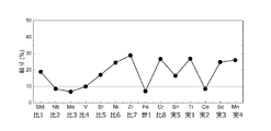
- FIG. 3 is a bar graph showing the area ratio of hydrogen embrittlement fracture (quasi-cleavage fracture and intergranular fracture) on the fracture surface of the aluminum alloy material of each example, each comparative example, and reference example 1 after the tensile test.
- FIG. 4 is a line graph showing the reduction of area of the aluminum alloy materials of each example, each comparative example, and reference example 1 after the tensile test.
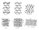
- FIG. 5(a) is a schematic diagram of the crystal structure of the Al 3 Sc particles formed in Example 3 and its hydrogen trap sites.
- FIG. 5(b) is a schematic diagram of the crystal structure of the Al 3 Ti particles formed in Example 1 and its hydrogen trap sites.
- FIG. 5(c) is a schematic diagram of the crystal structure of the Al 6 Mn particles formed in Example 4 and its hydrogen trap sites.
- FIG. 5(d) is a schematic diagram of the crystal structure of Al 9 Mn 4 particles.
- FIG. 5(e) is a schematic diagram of the crystal structure of Al 12 Mn 3 Si particles.
- FIG. 5(f) is a schematic diagram of the crystal structure of Al 31 Mn 6 Cu 2 particles.
- FIG. 6 is a number line diagram of the hydrogen trap energy of each microstructure in an aluminum alloy material.
- FIG. 7 is a plot diagram of the relationship between the maximum hydrogen trap energy inside the particle and the quasi-cleavage fracture area ratio.
- FIG. 8A is a schematic diagram of the crystal structure of Al 3 Y particles and their hydrogen trap sites.
- FIG. 8B is a schematic diagram of the crystal structure of Al 2 Ca particles and their hydrogen trap sites.
- FIG. 8(c) is a schematic diagram of the crystal structure of Al 7 Cr particles and their hydrogen trap sites.
- the hydrogen embrittlement inhibitor for aluminum alloy materials of the present invention can prevent hydrogen embrittlement of aluminum alloy materials, and is used to be contained as second phase particles inside aluminum alloy materials.
- the second phase particles are Sn particles, Al 11 Mn 3 Zn 2 particles, Al 9 Co 2 particles, Al 6 Mn particles, Al 3 Y particles, Al 3 Ti particles, Al 3 Sc particles, Al 2 Ca particles, Al7Cr particles, Al9Mn4 particles , Al12Mn3Si particles and Al31Mn6Cu2 particles .
- This configuration can effectively prevent or suppress hydrogen embrittlement of the aluminum alloy material.
- hydrogen embrittlement can be sufficiently effectively prevented or suppressed at the level required for the aircraft and space industries.
- the hydrogen embrittlement inhibitor for an aluminum alloy material of the present invention includes Sn particles, Al 11 Mn 3 Zn 2 particles, Al 9 Co 2 particles, Al 6 Mn particles, Al 3 Y particles, and Al having the above hydrogen trap sites. 3 Ti particles, Al 3 Sc particles, Al 2 Ca particles, Al 7 Cr particles, Al 9 Mn 4 particles, Al 12 Mn 3 Si particles and Al 31 Mn 6 Cu 2 particles. Hydrogen embrittlement cracking includes intergranular cracking and quasi-cleavage cracking. In the present invention, it is preferable that quasi-cleavage cracking can be effectively prevented or suppressed, and intergranular cracking and quasi-cleavage cracking can be effectively prevented or suppressed. Preferred embodiments of the present invention are described below.
- the raw aluminum alloy material to be prevented from hydrogen embrittlement may be a new aluminum alloy material or an existing aluminum alloy material.
- the hydrogen embrittlement inhibitor for aluminum alloy materials of the present invention is preferably capable of preventing hydrogen embrittlement of aluminum alloy materials of existing alloys within the JIS standard (JIS H 4000:2014, etc.) and/or new alloys outside the JIS standard.
- the raw aluminum alloy material contains aluminum as a main component, and preferably contains 50% by mass or more of aluminum.
- a preferred aspect of the raw aluminum alloy material is a pure aluminum alloy with a purity of 99.0% or more. Examples of pure aluminum alloys include 1000 series alloys such as A1050, A1100 and A1200.
- the raw aluminum alloy material it preferably contains at least Cu.
- Al--Cu alloys include 2000 series alloys such as A2017 and A2024.
- it preferably contains at least Mn.
- Al--Mn alloys include, for example, 3000 series alloys such as A3003, A3004 and A3005.
- it preferably contains at least Si.
- Al—Si alloys include 4000 series alloys such as A4042, A4043 and A4343.
- Examples of Al--Mg alloys include 5000 series alloys such as A5005, A5052, A5083 and A5182.
- the raw aluminum alloy material it preferably contains at least Mg and Si.
- Al--Mg--Si alloys include 6000 series alloys such as A6061 and A6063.
- it preferably contains at least Zn and Mg.
- Al--Zn--Mg alloys include 7000 series alloys such as A7075 and A7050 alloys.
- the aluminum alloy material is preferably an Al--Zn--Mg alloy containing at least Zn and Mg.
- Al--Zn--Mg alloys are alloys with the highest strength among wrought aluminum alloys for practical use, and are used in transportation equipment such as bullet trains and aircraft. This is because the strength of this alloy system is currently rate-determined by hydrogen embrittlement.
- the alloy composition of the aluminum alloy material obtained by adding the hydrogen embrittlement inhibitor of the aluminum alloy material of the present invention to the raw material aluminum alloy material is mainly composed of aluminum, and aluminum is 50% by mass. It is preferable to include the above.
- the preferred range of the alloy composition of such an aluminum alloy material is the range of the composition in which the hydrogen embrittlement inhibitor of the aluminum alloy material of the present invention is added in a preferred amount to the preferred aluminum alloy material of the raw material. .
- the shape of the aluminum alloy material is not particularly limited.
- the aluminum alloy material may be in the form of lumps or particles, preferably in the form of lumps.
- the second phase particles are Sn particles, Al 11 Mn 3 Zn 2 particles, Al 9 Co 2 particles, Al 6 Mn particles, Al 3 Y particles, Al 3 Ti particles, Al 3 Sc particles, Al 2 Ca particles, Al7Cr particles, Al9Mn4 particles , Al12Mn3Si particles and Al31Mn6Cu2 particles .
- Second phase particles refer to particles having a composition different from that of the mother phase.
- the second phase particles of the aluminum alloy material are particles of a composition different from that of Al or its aluminum alloy material.
- the second phase grains should have higher hydrogen trap energies than the coherent precipitate interfaces.
- the hydrogen trapping energy of the second phase particles should be at least higher than 0.35 eV/atom at the coherent precipitate interface.
- the second phase grains having a higher hydrogen trapping energy than the coherent precipitate interface.
- First-principles calculations can determine second-phase grains that have higher hydrogen trap energies than the coherent precipitate interface. The first-principles calculation is to express the electronic state theoretically by mathematically solving the Schrödinger equation (without using experimental data or empirical parameters). The distribution of hydrogen at each trap site can be calculated from the density of other hydrogen trap sites such as grain boundaries, precipitates, interstitial spaces, and the binding energy with hydrogen.
- the hydrogen trap energy of the second phase particles is preferably 0.40 eV/atom or more, more preferably 0.45 eV/atom or more, particularly preferably 0.50 eV/atom or more, and is semi-consistent More particularly preferred is higher than 0.55 eV of the precipitate interface.
- the second phase particles are Sn particles, Al 11 Mn 3 Zn 2 particles, Al 9 Co 2 particles, Al 6 Mn particles, Al 3 Ti particles, Al 3 Sc particles, Al 9 Mn 4 particles, Al 12 It preferably contains at least one of Mn3Si particles and Al31Mn6Cu2 particles, and includes Sn particles, Al11Mn3Zn2 particles , Al3Ti particles , Al3Sc particles , Al9Mn4 particles , More preferably, at least one of Al 12 Mn 3 Si particles and Al 31 Mn 6 Cu 2 particles is included.
- Sn particles, Al 11 Mn 3 Zn 2 particles, Al 9 Co 2 particles, Al 6 Mn particles, Al 3 Y particles, Al 3 Ti particles, Al 3 Sc particles, Al 2 Ca particles, Al 7 Cr particles, Al 9Mn4 particles , Al12Mn3Si particles and Al31Mn6Cu2 particles are particles in which the atomic ratio of each element other than Al deviates from the stoichiometric composition by within 20%. More preferably, the particles deviate within 10% from the stoichiometric composition, and most preferably, the particles deviate within 1% from the stoichiometric composition.
- Sn particles, Al 11 Mn 3 Zn 2 particles, Al 9 Co 2 particles, Al 6 Mn particles, Al 3 Y particles, Al 3 Ti particles, Al 3 Sc particles, Al 2 Ca particles, Al 7 Cr particles, Al 9 Mn 4 particles, Al 12 Mn 3 Si particles, and Al 31 Mn 6 Cu 2 particles can be expected to have similar effects even if they are particles in which a trace element is solid-dissolved in addition to each element constituting each particle.
- the particles in which trace elements are solid - dissolved are also the Sn particles and the Al11Mn3Zn2 particles of the present invention.
- the particles are preferably solid-dissolved particles, more preferably 10 mol % or less solid-dissolved particles, and particularly preferably 1 mol % or less solid-dissolved particles.
- Al 9 Co 2 particles may be particles composed of Al—Co—Mn—Mg, and such particles are included in the Al 9 Co 2 particles of the present invention.
- each trace element (For example, Mn element or Mg element) is independently preferably 30 mol % or less, more preferably 10 mol % or less, and particularly preferably 1 mol % or less relative to Al element.
- each trace element (for example, the total of Mn element and Mg element) is also preferably 30 mol% or less, more preferably 10 mol% or less, and 1 mol% or less with respect to Al element. is particularly preferred.
- Sn particles, Al 11 Mn 3 Zn 2 particles, Al 9 Co 2 particles, Al 6 Mn particles, Al 3 Y particles, Al 3 Ti particles, Al 3 Sc particles, Al 2 Ca particles, Al 7 The atomic ratio of each element other than Al that constitutes each of the Cr particles, Al 9 Mn 4 particles, Al 12 Mn 3 Si particles and Al 31 Mn 6 Cu 2 particles deviates within 30% from the stoichiometric composition, and A similar effect can be expected for particles in which a trace element is dissolved in addition to each element constituting each particle.
- the shape of the second phase particles includes various shapes such as spherical, ellipsoidal, prismatic, cylindrical, cubic, cuboid, and scale-like, preferably spherical or ellipsoidal.
- the volume fraction of the second phase particles is preferably 0.05 to 10.0%, more preferably 0.1 to 5.0%, particularly 0.5 to 2.0%. preferable.
- the volume ratio of the second phase particles can be calculated as the volume of the second phase particles with respect to the volume of the aluminum alloy material, for example, by 3D analysis using X-ray tomography (CT).
- the number density of the second phase particles can be from 0.01 ⁇ 10 17 /m 3 to 100 ⁇ 10 17 /m 3 .
- the number density of the second phase particles is preferably 0.1 ⁇ 10 17 /m 3 to 10 ⁇ 10 17 /m 3 , and 0.2 ⁇ 10 17 /m 3 to 5 ⁇ 10 17 /m 3 0.2 ⁇ 10 17 /m 3 to 3 ⁇ 10 17 /m 3 is particularly preferred.
- the number density of the second-phase particles can be calculated, for example, by 3D analysis using high-resolution X-ray tomography (CT) with a spatial resolution of up to 1 ⁇ m.
- CT high-resolution X-ray tomography
- the average particle size of the second phase particles is preferably 0.1 to 20 ⁇ m.
- the upper limit of the average particle size of the second phase particles is more preferably 10 ⁇ m or less, particularly preferably 5.0 ⁇ m or less. More preferably, the lower limit of the average particle size of the second phase particles is 0.5 ⁇ m or more.
- the average particle size of the second phase particles can be calculated as an arithmetic average by 3D analysis using, for example, X-ray tomography (CT).
- ⁇ Method for preventing hydrogen embrittlement of aluminum alloy material There are no particular restrictions on the method for preventing hydrogen embrittlement of aluminum alloy materials or the method for producing aluminum alloy materials. Sn particles, Al 11 Mn 3 Zn 2 particles, Al 9 Co 2 particles, Al 6 Mn particles, Al 3 Y particles, Al 3 Ti particles, Al 3 Sc particles, and Al 2 Ca particles for the raw material aluminum alloy material , Al 7 Cr particles, Al 9 Mn 4 particles, Al 12 Mn 3 Si particles and Al 31 Mn 6 Cu 2 particles. , the hydrogen embrittlement of the aluminum alloy material can be prevented.
- These 12 types of particles may be added to the raw aluminum alloy material, and elements (Sn, Co, Mn, Y, Ti, Sc, Ca, Cr) corresponding to these 12 types of particles may be added during production. , Si or Cu) may be added to form these 12 types of particles, and finally these 12 types of particles may be used as a hydrogen embrittlement inhibitor (in the case of Al 6 Mn particles, the raw material aluminum increasing the Mn concentration of the alloy material, etc.). No special manufacturing equipment or manufacturing conditions are required. These particles can be formed by thermomechanical treatment during alloy manufacture.
- the raw material aluminum alloy material may be a raw material mixture before each metal including Al or a metal compound is alloyed.
- An aluminum alloy material can be produced by known processes such as heat treatment, rolling, forging and/or casting of a raw material aluminum alloy material (which may be a mixture of raw materials).
- a raw material aluminum alloy material which may be a mixture of raw materials.
- elements Sn, Co, Mn, Y, Ti, Sc, Ca, Cr, Si or Cu
- Sn particles Sn particles, Al 11 Mn 3 Zn 2 particles, Al 9 Co 2 particles, Al 6 Mn particles, Al 3 Y particles, Al 3 Ti particles
- heat treatment, rolling, and forging may not be performed.
- the chemical composition of Al-10.0Zn-1.06Mg-M corresponds to 12 types of particles during casting.
- the amount of the fourth element to be added is preferably 0.05 to 5.00% by mass, more preferably 0.10 to 3.00% by mass, and more preferably 0.15 to 2.00% by mass. 50% by mass is particularly preferred.
- An example of a more preferable range of the addition amount of the fourth element in this case is as follows.
- the fourth element is Co, it is preferably 0.05 to 0.50% by mass, more preferably 0.10 to 0.30% by mass, and particularly preferably 0.15 to 0.25% by mass.
- the fourth element is Sc, it is preferably 0.10 to 2.00% by mass, more preferably 0.50 to 1.50% by mass, and particularly preferably 0.80 to 1.00% by mass.
- the fourth element is Ti, it is preferably 0.10 to 2.00% by mass, more preferably 0.50 to 1.50% by mass, and particularly preferably 0.90 to 1.10% by mass.
- the fourth element is Mn, it is preferably 0.50 to 5.00% by mass, more preferably 1.00 to 3.00% by mass, particularly preferably 1.50 to 2.50% by mass, and 1.80 to 2.00% by mass is more particularly preferred.
- An aluminum alloy material satisfying the chemical composition of Al-10.0Zn-1.06Mg-M (M is the fourth element) was prepared by the following method.
- This aluminum alloy material is also an Al--Zn--Mg alloy containing 50% by mass or more of Al as the main component.
- Table 1 below shows the addition amounts (unit: mass %) of the 13 types of the fourth element (M). This addition amount is adjusted so that the volume ratio of the compound formed in the aluminum is approximately the same.
- the fourth element material was added to the smelter to form second phase particles inside the material. Specifically, heating at 500 ° C. for 24 hours (homogenization), heating at 450 ° C. (hot rolling), heating at 500 ° C. for 5 hours (solution treatment), heating at 120 ° C. for 40 hours and 180 ° C. for 7 hours. Overaging was performed. The obtained non-discharge-machined aluminum alloy material was subjected to underwater discharge machining (EDM) to prepare a test piece with an increased amount of hydrogen.
- EDM underwater discharge machining
- Figs. 1(a) to 1(e) show virtual cross sections of the inside of each aluminum alloy material observed by synchrotron radiation nanotomography.
- Fig. 1(a) shows a virtual cross section of a tomography tomographic image of the microstructure of the aluminum alloy material of Example 3 (the fourth element M is Sc).
- Fig. 1(b) shows a virtual cross section of a tomography tomographic image of the microstructure of the aluminum alloy material of Comparative Example 7 (where the fourth element M is Zr).
- Fig. 1(a) shows a virtual cross section of a tomography tomographic image of the microstructure of the aluminum alloy material of Comparative Example 7 (where the fourth element M is Zr).
- FIG. 1(c) shows a virtual cross section of a tomography tomographic image of the microstructure of the aluminum alloy material of Example 4 (where the fourth element M is Mn).
- FIG. 1(d) shows a virtual cross section of a tomography tomographic image of the microstructure of the aluminum alloy material of Comparative Example 8 (the fourth element M is Cr).
- Fig. 1(e) shows a virtual cross section of a tomography tomographic image of the microstructure of the aluminum alloy material of Comparative Example 6 (where the fourth element M is Ni). Illustrations of other examples, comparative examples, and reference example 1 are omitted.
- FIG. 2(a) shows a fracture surface of the aluminum alloy material (Std.: no fourth element M) of Comparative Example 1 after the tensile test.
- FIG. 2(b) shows the fracture surface of the aluminum alloy material (the fourth element M is Zr) of Comparative Example 7 after the tensile test.
- FIG. 2(c) shows a fracture surface of the aluminum alloy material (the fourth element M is Cr) of Comparative Example 8 after the tensile test.
- FIG. 2(d) shows the fracture surface of the aluminum alloy material (the fourth element M is Sc) of Example 3 after the tensile test.
- FIG. 2(e) shows the fracture surface of the aluminum alloy material of Example 4 (the fourth element M is Mn) after the tensile test.
- FIG. 2( f ) shows the fracture surface of the aluminum alloy material (the fourth element M is Ti) of Example 1 after the tensile test.
- FIG. 2(g) shows the fracture surface of the aluminum alloy material (the fourth element M is Ni) of Comparative Example 6 after the tensile test. Illustrations of other examples, comparative examples, and reference example 1 are omitted.
- the hydrogen embrittlement inhibitors for aluminum alloy materials of Examples 1 to 5 can effectively prevent or suppress quasi-cleavage fracture of aluminum alloy materials, and are extremely effective as hydrogen embrittlement inhibitors for aluminum alloy materials. It turns out there is. Furthermore, from FIG. 3, according to a preferred embodiment of the present invention, the hydrogen embrittlement inhibitor for aluminum alloy materials of the present invention can effectively prevent or suppress intergranular fracture of aluminum alloy materials, and hydrogen embrittlement of aluminum alloy materials can be prevented. It was found that the fracture surface ratio (intergranular fracture and quasi-cleavage fracture) can be improved.
- FIGS. 5(a) to 5(c) The crystal structure (first-principles calculation model) of particles formed by adding elements and their hydrogen trap sites are shown in FIGS. 5(a) to 5(c).
- the crystal structure of the Al 3 Ti particles formed in Example 1 (where the fourth element M is Ti) and its hydrogen trap sites are shown in FIG. 5(b).
- the crystal structure of Al 6 Mn particles formed in Example 4 (where the fourth element M is Mn) and its hydrogen trap sites are shown in FIG. 5(c). Illustrations of other examples, comparative examples, and reference example 1 are omitted. From FIGS.
- the hydrogen trap energy is 0.785 eV/atom, 0.656 eV/atom and 0.883 eV/atom, all higher than 0.35 eV/atom for coherent precipitate interfaces and 0.55 eV/atom for semi-coherent precipitate interfaces. From the positive correlation between the hydrogen trap energy inside the particles and the quasi - cleavage fracture area ratio shown in FIG .
- FIG. 6 shows the result of calculating the hydrogen trapping energy of each microstructure in the aluminum alloy material by first-principles calculation and the desired hydrogen trapping energy of the intermetallic compound particles (IMC particles).
- IMC particles intermetallic compound particles
- the hydrogen trap energy of the intermetallic compound particles (IMC particles) must be higher than at least 0.35 eV/atom of the coherent precipitate interface ( ⁇ 1 , coherent). Furthermore, in a preferred embodiment of the present invention, the hydrogen trapping energy of the intermetallic compound particles (IMC particles) is preferably higher than 0.55 eV/atom of the semi-coherent precipitate interface ( ⁇ 2 , semi-coherent). Separation of the ⁇ /Al interface due to hydrogen traps was calculated by first-principles calculations.
- Table 3 shows the results of calculating the hydrogen trap energy inside the particles.
- the hydrogen trap energy is 0.00% of the coherent precipitate interface ( ⁇ 1 , coherent). It was found to be higher than 35 eV/atom. Furthermore, when the hydrogen embrittlement inhibitor of the aluminum alloy material of Example 1, 3 or 5 of the preferred embodiment of the present invention is contained inside the material as a second phase particle, the hydrogen trap energy is semi-coherent precipitate interface ( ⁇ 2 , semi-coherent) is higher than 0.55 eV/atom.
- FIG. 7 shows the relationship between the maximum hydrogen trap energy (E IMC ) inside the particle and the area fraction of quasi-cleavage fracture (A QCF ).
- E IMC maximum hydrogen trap energy
- a QCF area fraction of quasi-cleavage fracture
- FIG. 7 shows the relationship between the maximum hydrogen trap energy (E IMC ) inside the particle and the area fraction of quasi-cleavage fracture (A QCF ).
- QCF means quasi-cleavage creak. It can be read from FIG. 7 that there is a positive correlation between the hydrogen trap energy inside the particle and the quasi-cleavage fracture area ratio. It was found that hydrogen embrittlement can be prevented on the fractured surface after the tensile test. From the above, it was found that hydrogen embrittlement can be reduced by incorporating the hydrogen embrittlement inhibitor for the aluminum alloy materials of Examples 1 to 5 as second phase particles inside the materials.
- the hydrogen embrittlement inhibitors for the aluminum alloy materials of Examples 1 to 4 were contained in the aluminum alloy material in micron order, at high density and dispersedly.
- the hydrogen embrittlement inhibitors for aluminum alloy materials of Examples 1 to 5 can effectively prevent or suppress quasi-cleavage fracture of aluminum alloy materials, preferably prevent or suppress intergranular fracture, and prevent hydrogen embrittlement of aluminum alloy materials. It has been found to be very effective as an inhibitor.
Abstract
Cet agent de prévention de fragilisation par l'hydrogène pour un matériau en alliage d'aluminium peut empêcher la fragilisation par l'hydrogène dans un matériau en alliage d'aluminium, et est destiné à une utilisation dans laquelle l'agent de prévention de la fragilisation par l'hydrogène est inclus en tant que secondes particules de phase à l'intérieur d'un matériau en alliage d'aluminium. Les secondes particules de phase comprennent au moins un type de particules parmi des particules de Sn, des particules de Al11Mn3Zn2, des particules de Al9Co2, des particules de Al6Mn, des particules de Al3Y, des particules de Al3Ti, des particules de Al3Sc, des particules de Al2Ca, des particules de Al7Cr, des particules de Al9Mn4, des particules de Al12Mn3Si et des particules de Al31Mn6Cu2. Cet agent de prévention de fragilisation par l'hydrogène pour un matériau en alliage d'aluminium peut empêcher ou supprimer efficacement la fragilisation par l'hydrogène.
Priority Applications (1)
| Application Number | Priority Date | Filing Date | Title |
|---|---|---|---|
| JP2023530471A JPWO2022270483A1 (fr) | 2021-06-22 | 2022-06-21 |
Applications Claiming Priority (2)
| Application Number | Priority Date | Filing Date | Title |
|---|---|---|---|
| JP2021-103677 | 2021-06-22 | ||
| JP2021103677 | 2021-06-22 |
Publications (1)
| Publication Number | Publication Date |
|---|---|
| WO2022270483A1 true WO2022270483A1 (fr) | 2022-12-29 |
Family
ID=84545728
Family Applications (1)
| Application Number | Title | Priority Date | Filing Date |
|---|---|---|---|
| PCT/JP2022/024630 WO2022270483A1 (fr) | 2021-06-22 | 2022-06-21 | Agent de prévention de fragilisation par l'hydrogène pour matériau en alliage d'aluminium |
Country Status (2)
| Country | Link |
|---|---|
| JP (1) | JPWO2022270483A1 (fr) |
| WO (1) | WO2022270483A1 (fr) |
Citations (9)
| Publication number | Priority date | Publication date | Assignee | Title |
|---|---|---|---|---|
| JPS62188762A (ja) * | 1987-02-05 | 1987-08-18 | Res Inst Electric Magnetic Alloys | Al―Sn吸振合金およびその製造方法 |
| JP2006336104A (ja) * | 2005-05-31 | 2006-12-14 | United Technol Corp <Utc> | 高温アルミニウム合金 |
| JP2009197249A (ja) * | 2008-02-19 | 2009-09-03 | Furukawa-Sky Aluminum Corp | 高圧水素ガス用アルミニウム合金及び高圧水素ガス用アルミニウム合金クラッド材 |
| JP2009221566A (ja) * | 2008-03-18 | 2009-10-01 | Kobe Steel Ltd | 耐水素脆化特性に優れた高圧ガス容器用アルミニウム合金材 |
| JP2010126741A (ja) * | 2008-11-25 | 2010-06-10 | Nissan Motor Co Ltd | 中空アルミニウム合金とその製造方法 |
| JP2011214149A (ja) * | 2010-03-18 | 2011-10-27 | Kobe Steel Ltd | 高圧水素ガス貯蔵容器用アルミニウム合金材 |
| JP2014009398A (ja) * | 2012-07-03 | 2014-01-20 | Uacj Corp | 高圧水素ガス容器用のAl−Mg系合金 |
| JP2016204712A (ja) * | 2015-04-24 | 2016-12-08 | 株式会社Uacj | 塩水空気電池用アルミニウム負極材、塩水アルミニウム空気電池および塩水空気電池用アルミニウム負極材の製造方法 |
| JP2020084234A (ja) * | 2018-11-20 | 2020-06-04 | 日本軽金属株式会社 | アルミニウム合金製ライナー及びその製造方法 |
-
2022
- 2022-06-21 WO PCT/JP2022/024630 patent/WO2022270483A1/fr active Application Filing
- 2022-06-21 JP JP2023530471A patent/JPWO2022270483A1/ja active Pending
Patent Citations (9)
| Publication number | Priority date | Publication date | Assignee | Title |
|---|---|---|---|---|
| JPS62188762A (ja) * | 1987-02-05 | 1987-08-18 | Res Inst Electric Magnetic Alloys | Al―Sn吸振合金およびその製造方法 |
| JP2006336104A (ja) * | 2005-05-31 | 2006-12-14 | United Technol Corp <Utc> | 高温アルミニウム合金 |
| JP2009197249A (ja) * | 2008-02-19 | 2009-09-03 | Furukawa-Sky Aluminum Corp | 高圧水素ガス用アルミニウム合金及び高圧水素ガス用アルミニウム合金クラッド材 |
| JP2009221566A (ja) * | 2008-03-18 | 2009-10-01 | Kobe Steel Ltd | 耐水素脆化特性に優れた高圧ガス容器用アルミニウム合金材 |
| JP2010126741A (ja) * | 2008-11-25 | 2010-06-10 | Nissan Motor Co Ltd | 中空アルミニウム合金とその製造方法 |
| JP2011214149A (ja) * | 2010-03-18 | 2011-10-27 | Kobe Steel Ltd | 高圧水素ガス貯蔵容器用アルミニウム合金材 |
| JP2014009398A (ja) * | 2012-07-03 | 2014-01-20 | Uacj Corp | 高圧水素ガス容器用のAl−Mg系合金 |
| JP2016204712A (ja) * | 2015-04-24 | 2016-12-08 | 株式会社Uacj | 塩水空気電池用アルミニウム負極材、塩水アルミニウム空気電池および塩水空気電池用アルミニウム負極材の製造方法 |
| JP2020084234A (ja) * | 2018-11-20 | 2020-06-04 | 日本軽金属株式会社 | アルミニウム合金製ライナー及びその製造方法 |
Also Published As
| Publication number | Publication date |
|---|---|
| JPWO2022270483A1 (fr) | 2022-12-29 |
Similar Documents
| Publication | Publication Date | Title |
|---|---|---|
| Ghiaasiaan et al. | Quantitative metallography of precipitating and secondary phases after strengthening treatment of net shaped casting of Al-Zn-Mg-Cu (7000) alloys | |
| JP6412103B2 (ja) | 構造用アルミニウム合金板及びその製造方法 | |
| Su et al. | Additive manufacturing of fine-grained high-strength titanium alloy via multi-eutectoid elements alloying | |
| Shriwas et al. | Impact of aluminum alloys and microstructures on engineering propertiesreview | |
| Zhu et al. | Selective laser melting of micron-sized niobium functionalized Al7075 alloy: element evaporation and grain refinement | |
| Schliephake et al. | Improved work hardening capability and ductility of an additively manufactured and deformed Al-Mn-Mg-Sc-Zr alloy | |
| Liang et al. | Effects of rare earth modification on microstructure refinement and mechanical properties of Al-2 wt% Fe alloys | |
| US11608546B2 (en) | Aluminum-cerium-manganese alloy embodiments for metal additive manufacturing | |
| JP5379463B2 (ja) | Lng球形タンク用高強度アルミニウム合金の製造方法 | |
| JP7273174B2 (ja) | アルミニウム系合金 | |
| WO2022270483A1 (fr) | Agent de prévention de fragilisation par l'hydrogène pour matériau en alliage d'aluminium | |
| Yin et al. | Precipitation/recovery kinetics and mechanical properties in rapidly solidified AA6005 AlMgSi sheets via thin strip casting: Effects of casting cooling rate and thermomechanical processing route | |
| WO2021246267A1 (fr) | Matériau d'alliage d'aluminium et inhibiteur de fragilisation par l'hydrogène pour matériaux d'alliage d'aluminium | |
| Hajizamani et al. | A comparative study on characteristics of nanostructured Al–Zn–Mg/3 wt% Al2O3 composites synthesized through solid-state sintering and semi-solid thermomechanical processing | |
| Ozgowicz et al. | The structure and mechanical properties of Al-Mg-Mn alloys shaped in the process of thermomechanical treatment | |
| Rathi et al. | Effect of heat treatment for enhancing performance of Al–5Ti–1B master alloy on mechanical and hot tearing properties of Al–7Si–3Cu alloy | |
| WO2023195480A1 (fr) | Procédé d'inhibition de la fragilisation par l'hydrogène d'un matériau en alliage d'aluminium, et inhibiteur de fragilisation par l'hydrogène | |
| JP7471499B1 (ja) | アルミニウム合金クラッド材 | |
| Monti et al. | Microstructure and mechanical properties of AlTiCrFe and AlTiCrCu alloys processed by Laser Powder Bed Fusion | |
| WO2022091948A1 (fr) | Alliage d'aluminium pour composant coulissant, et composant coulissant | |
| WO2022091936A1 (fr) | Alliage d'aluminium pour éléments coulissants, et élément coulissant | |
| Tian et al. | Microstructure and properties of a novel Ni-Ti-Cr-Mo-Nb alloy fabricated in situ by dual-wire arc additive manufacturing | |
| Ovsyannikov et al. | Development of a new aluminum-lithium alloy of Al–Cu–Mg–Li (Ag, Sc) system intended for manufacturing sheets, thin-walled sections and forgings | |
| Carroll | Improvements to the strength and corrosion resistance of aluminum-magnesium-manganese alloys of near-AA5083 chemistry | |
| JP6927418B2 (ja) | チタン合金およびその製造方法 |
Legal Events
| Date | Code | Title | Description |
|---|---|---|---|
| 121 | Ep: the epo has been informed by wipo that ep was designated in this application |
Ref document number: 22828400 Country of ref document: EP Kind code of ref document: A1 |
|
| WWE | Wipo information: entry into national phase |
Ref document number: 2023530471 Country of ref document: JP |
|
| NENP | Non-entry into the national phase |
Ref country code: DE |