WO2022270180A1 - 超音波診断装置および超音波診断装置の制御方法 - Google Patents
超音波診断装置および超音波診断装置の制御方法 Download PDFInfo
- Publication number
- WO2022270180A1 WO2022270180A1 PCT/JP2022/020305 JP2022020305W WO2022270180A1 WO 2022270180 A1 WO2022270180 A1 WO 2022270180A1 JP 2022020305 W JP2022020305 W JP 2022020305W WO 2022270180 A1 WO2022270180 A1 WO 2022270180A1
- Authority
- WO
- WIPO (PCT)
- Prior art keywords
- stool
- ultrasonic
- region
- image
- unit
- Prior art date
- Legal status (The legal status is an assumption and is not a legal conclusion. Google has not performed a legal analysis and makes no representation as to the accuracy of the status listed.)
- Ceased
Links
Images





Classifications
-
- A—HUMAN NECESSITIES
- A61—MEDICAL OR VETERINARY SCIENCE; HYGIENE
- A61B—DIAGNOSIS; SURGERY; IDENTIFICATION
- A61B8/00—Diagnosis using ultrasonic, sonic or infrasonic waves
- A61B8/08—Clinical applications
- A61B8/0833—Clinical applications involving detecting or locating foreign bodies or organic structures
-
- A—HUMAN NECESSITIES
- A61—MEDICAL OR VETERINARY SCIENCE; HYGIENE
- A61B—DIAGNOSIS; SURGERY; IDENTIFICATION
- A61B8/00—Diagnosis using ultrasonic, sonic or infrasonic waves
- A61B8/42—Details of probe positioning or probe attachment to the patient
- A61B8/4245—Details of probe positioning or probe attachment to the patient involving determining the position of the probe, e.g. with respect to an external reference frame or to the patient
-
- A—HUMAN NECESSITIES
- A61—MEDICAL OR VETERINARY SCIENCE; HYGIENE
- A61B—DIAGNOSIS; SURGERY; IDENTIFICATION
- A61B8/00—Diagnosis using ultrasonic, sonic or infrasonic waves
- A61B8/42—Details of probe positioning or probe attachment to the patient
- A61B8/4245—Details of probe positioning or probe attachment to the patient involving determining the position of the probe, e.g. with respect to an external reference frame or to the patient
- A61B8/4254—Details of probe positioning or probe attachment to the patient involving determining the position of the probe, e.g. with respect to an external reference frame or to the patient using sensors mounted on the probe
-
- A—HUMAN NECESSITIES
- A61—MEDICAL OR VETERINARY SCIENCE; HYGIENE
- A61B—DIAGNOSIS; SURGERY; IDENTIFICATION
- A61B8/00—Diagnosis using ultrasonic, sonic or infrasonic waves
- A61B8/42—Details of probe positioning or probe attachment to the patient
- A61B8/4272—Details of probe positioning or probe attachment to the patient involving the acoustic interface between the transducer and the tissue
- A61B8/429—Details of probe positioning or probe attachment to the patient involving the acoustic interface between the transducer and the tissue characterised by determining or monitoring the contact between the transducer and the tissue
-
- A—HUMAN NECESSITIES
- A61—MEDICAL OR VETERINARY SCIENCE; HYGIENE
- A61B—DIAGNOSIS; SURGERY; IDENTIFICATION
- A61B8/00—Diagnosis using ultrasonic, sonic or infrasonic waves
- A61B8/46—Ultrasonic, sonic or infrasonic diagnostic devices with special arrangements for interfacing with the operator or the patient
- A61B8/461—Displaying means of special interest
-
- A—HUMAN NECESSITIES
- A61—MEDICAL OR VETERINARY SCIENCE; HYGIENE
- A61B—DIAGNOSIS; SURGERY; IDENTIFICATION
- A61B8/00—Diagnosis using ultrasonic, sonic or infrasonic waves
- A61B8/46—Ultrasonic, sonic or infrasonic diagnostic devices with special arrangements for interfacing with the operator or the patient
- A61B8/461—Displaying means of special interest
- A61B8/463—Displaying means of special interest characterised by displaying multiple images or images and diagnostic data on one display
-
- A—HUMAN NECESSITIES
- A61—MEDICAL OR VETERINARY SCIENCE; HYGIENE
- A61B—DIAGNOSIS; SURGERY; IDENTIFICATION
- A61B8/00—Diagnosis using ultrasonic, sonic or infrasonic waves
- A61B8/46—Ultrasonic, sonic or infrasonic diagnostic devices with special arrangements for interfacing with the operator or the patient
- A61B8/467—Ultrasonic, sonic or infrasonic diagnostic devices with special arrangements for interfacing with the operator or the patient characterised by special input means
- A61B8/469—Ultrasonic, sonic or infrasonic diagnostic devices with special arrangements for interfacing with the operator or the patient characterised by special input means for selection of a region of interest
-
- A—HUMAN NECESSITIES
- A61—MEDICAL OR VETERINARY SCIENCE; HYGIENE
- A61B—DIAGNOSIS; SURGERY; IDENTIFICATION
- A61B8/00—Diagnosis using ultrasonic, sonic or infrasonic waves
- A61B8/52—Devices using data or image processing specially adapted for diagnosis using ultrasonic, sonic or infrasonic waves
- A61B8/5215—Devices using data or image processing specially adapted for diagnosis using ultrasonic, sonic or infrasonic waves involving processing of medical diagnostic data
- A61B8/5223—Devices using data or image processing specially adapted for diagnosis using ultrasonic, sonic or infrasonic waves involving processing of medical diagnostic data for extracting a diagnostic or physiological parameter from medical diagnostic data
-
- A—HUMAN NECESSITIES
- A61—MEDICAL OR VETERINARY SCIENCE; HYGIENE
- A61B—DIAGNOSIS; SURGERY; IDENTIFICATION
- A61B8/00—Diagnosis using ultrasonic, sonic or infrasonic waves
- A61B8/54—Control of the diagnostic device
-
- A—HUMAN NECESSITIES
- A61—MEDICAL OR VETERINARY SCIENCE; HYGIENE
- A61B—DIAGNOSIS; SURGERY; IDENTIFICATION
- A61B8/00—Diagnosis using ultrasonic, sonic or infrasonic waves
- A61B8/44—Constructional features of the ultrasonic, sonic or infrasonic diagnostic device
- A61B8/4427—Device being portable or laptop-like
-
- A—HUMAN NECESSITIES
- A61—MEDICAL OR VETERINARY SCIENCE; HYGIENE
- A61B—DIAGNOSIS; SURGERY; IDENTIFICATION
- A61B8/00—Diagnosis using ultrasonic, sonic or infrasonic waves
- A61B8/44—Constructional features of the ultrasonic, sonic or infrasonic diagnostic device
- A61B8/4483—Constructional features of the ultrasonic, sonic or infrasonic diagnostic device characterised by features of the ultrasound transducer
- A61B8/4488—Constructional features of the ultrasonic, sonic or infrasonic diagnostic device characterised by features of the ultrasound transducer the transducer being a phased array
-
- A—HUMAN NECESSITIES
- A61—MEDICAL OR VETERINARY SCIENCE; HYGIENE
- A61B—DIAGNOSIS; SURGERY; IDENTIFICATION
- A61B8/00—Diagnosis using ultrasonic, sonic or infrasonic waves
- A61B8/46—Ultrasonic, sonic or infrasonic diagnostic devices with special arrangements for interfacing with the operator or the patient
Definitions
- the present invention relates to an ultrasonic diagnostic apparatus having a function of identifying the presence or absence of stool in an ultrasonic image, and furthermore, a function of specifying stool properties, and a control method for the ultrasonic diagnostic apparatus.
- Patent Document 1 information on ultrasonic echo signals obtained from the large intestine using ultrasonic waves is used to determine whether the state of stool inside the large intestine is normal, hard stool, gas accumulation, or soft stool.
- a diagnostic device is described with which it is possible to assess whether Further, Patent Document 1 describes a diagnostic apparatus that obtains ultrasound image data of the large intestine using echo signals and evaluates whether or not the condition of stool inside the large intestine is loose stool in the ultrasound image data. It is
- Patent Document 2 describes reference images acquired by various medical image diagnostic apparatuses such as CT images according to the diagnostic purpose of the subject and the type of ultrasonic probe to be used.
- the position sensor attached to the ultrasound probe is used to align the ultrasound image with the reference image, the ultrasound image and the reference image are displayed, and the ultrasound image is positioned at the position of the lesion.
- a probe navigating ultrasound diagnostic system is described.
- an object of the present invention is to provide an ultrasonic diagnostic apparatus and a control method for the ultrasonic diagnostic apparatus that can reliably identify the presence or absence of stool from an ultrasonic image.
- the present invention provides an ultrasonic image based on a received signal obtained by scanning an inspection location of a subject with an ultrasonic beam using an ultrasonic probe, a monitor, and the ultrasonic probe.
- a display control unit for displaying an ultrasound image on a monitor;
- a stool information detection unit for detecting a stool region from the ultrasound image;
- a stool identification unit a stool information display unit that highlights a stool region in an ultrasound image displayed on a monitor when the presence of stool is identified, and a stool identification unit that identifies the presence of stool within a predetermined period.
- an annunciation unit that annunciates a message suggesting a change in the approach of an ultrasound probe when performing a scan when an ultrasonic diagnostic apparatus is not used.
- the stool information detection unit uses at least one of template matching, machine learning using image feature values, and a deep learning model to detect the stool region from the ultrasound image.
- the stool identification unit identifies that there is stool when a stool region is detected from one frame of the ultrasound image.
- the stool identification unit identifies that there is stool when a stool region is detected from ultrasonic images of a predetermined number or more of consecutive frames of ultrasonic images.
- the stool identification unit performs the same determination to determine whether or not the stool regions in the ultrasonic images of adjacent frames are the same stool region, and the number of frames of the ultrasonic images in which the same stool region is detected is preferably counted as a defined number of frames.
- the stool identification unit preferably makes the same determination for each stool region.
- the stool information detection unit detects a stool region and the probability that the stool region is a stool region for each frame of the ultrasound image
- the stool identification unit detects the statistic value of the probability of the ultrasound images of a plurality of frames. It is preferable to identify the presence or absence of stool by comparing with a threshold value.
- the stool information detection unit detects the probability that a pixel is a stool pixel for each frame of the ultrasonic image and for each pixel of the ultrasonic image, and calculates the probability that the pixel is a stool pixel and the first threshold. By the comparison, it is determined whether or not the pixels are the pixels of stool, and an aggregate of a plurality of pixels determined to be pixels of stool is detected as a stool region. Statistical values of probabilities of all pixels in the stool region of the ultrasonic image are obtained as index values, and the presence or absence of stool is identified by comparing the statistical values of the index values of the ultrasonic images of a plurality of frames with a second threshold. preferably.
- a contact detection unit for detecting whether or not the ultrasonic probe has come into contact with the examination location of the subject, and measurement for a predetermined period indicates that the ultrasonic probe has come into contact with the examination location of the subject. It is preferable to start immediately after detection.
- a motion detection unit that detects the presence or absence of motion of the ultrasonic probe, and to measure only the time when the motion of the ultrasonic probe is detected as a predetermined period.
- the motion detection unit detects at least one of an image analysis result of the ultrasonic image, a motion detection result by a motion sensor provided in the ultrasonic probe, and a pressure detection result by a pressure sensor provided in the ultrasonic probe. It is preferable to detect the presence or absence of movement of the ultrasonic probe based on .
- the notification unit notifies a message indicating that there is a flight when it is specified that there is a flight.
- an approach determination unit that determines an approach is provided, and the notification unit performs scanning from a plurality of preset approaches when it is not specified that there will be a flight within a predetermined period. preferably selects a different approach and broadcasts a message suggesting a change to a different approach than the scanning approach.
- the notification unit notifies a message indicating that there is no flight when none of the preset multiple approaches identify that there is a flight.
- the stool information detection unit further detects stool condition information of the stool region from the ultrasound image, the stool identification unit further identifies stool characteristics of the stool region based on the stool condition information, and the stool information display unit
- the stool region is highlighted in the ultrasound image displayed on the monitor, and the notification unit indicates that there is stool within a predetermined period. is not identified, or if a flight is identified but no stool properties are identified, then a message suggesting a change in approach is preferably broadcast.
- the stool information detection unit detects the statistic value of the luminance within the stool region for each frame of the ultrasound image
- the stool identification unit detects the statistic value of the luminance within the stool region for each frame of the ultrasound image.
- a first comparison result is obtained by comparing with a third threshold, and the stool properties are specified based on the first comparison result in the ultrasound image of one frame or a plurality of frames;
- the stool identification unit detects the luminance ratio between the statistic value of luminance in the feces region and the statistic value of luminance in a defined region around the feces region
- a second comparison result is obtained by comparing the luminance ratio with a fourth threshold value, and the fecal properties are specified based on the second comparison result in the ultrasound image of one frame or a plurality of frames.
- the stool information detection unit detects the stool area and the probability that the stool area belongs to each class of stool properties, and the stool identification unit selects the class with the highest probability among the stool properties classes as the stool properties of the stool area. It is preferred to specify.
- the stool information detection unit detects, for each pixel of the ultrasound image, the probability that the pixel belongs to each class of stool properties, and determines the class with the highest probability among the classes of stool properties as the class of the pixel, A collection of a plurality of pixels determined to be stool pixels based on the pixel class is detected as a stool region, and the stool identifying unit obtains the total area of each class of stool properties, and the total area is Preferably, the largest class is identified as the stool attribute of the stool area.
- the stool identification unit identifies the presence of stool when a stool region is detected from one frame of the ultrasonic image and the stool properties of the stool region detected from the one frame of ultrasonic image are identified. is preferred.
- the stool identification unit detects a stool region from ultrasonic images of a predetermined first number or more of ultrasonic images of a plurality of consecutive frames, and Among them, it is preferable to specify that there is stool when the stool properties of the stool regions detected from the second number of frames or more of the ultrasound images are the same.
- the stool identification unit performs the same determination to determine whether or not the stool regions in the ultrasonic images of adjacent frames are the same stool region, and the number of frames of the ultrasonic images in which the same stool region is detected is counted as the first number of frames defined and the second number of frames defined.
- a first mode of operation that specifies neither the presence or absence of stool nor stool texture
- a second mode of operation that specifies the presence or absence of stool but does not specify stool texture
- a second mode of operation that identifies both the presence or absence of stool and stool texture. It is preferable to have at least two operation modes out of the third operation modes, and to provide a mode switching unit that switches to one operation mode out of the at least two operation modes according to an instruction from the user.
- the statistical value is preferably an average value, a weighted average value or a median value.
- the present invention provides a step in which an image generating unit generates an ultrasonic image based on a received signal obtained by scanning an examination location of a subject with an ultrasonic beam using an ultrasonic probe, and a display control unit. a step of displaying an ultrasound image on a monitor; a step of detecting a stool region from the ultrasound image by the stool information detection unit; a step in which the stool information display unit highlights the stool region in the ultrasound image displayed on the monitor when the presence of stool is specified; and issuing a message suggesting a change in the approach of the ultrasound probe when performing a scan if no problem is identified.
- the stool area is highlighted in the ultrasound image displayed on the monitor, so that the user can easily grasp the stool area in the ultrasound image. can be done.
- a message suggesting a change in approach is notified. can be identified with certainty.
- FIG. 1 is a block diagram of an embodiment showing the configuration of an ultrasonic diagnostic apparatus of the present invention
- FIG. 1 is a block diagram of an embodiment showing the configuration of a transmission/reception circuit
- FIG. It is a block diagram of one embodiment showing the configuration of the image generator.
- It is a block diagram of one embodiment showing the configuration of the stool processing unit.
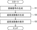
- 1 is a flowchart of one embodiment representing operation of an ultrasound diagnostic apparatus in a first mode of operation
- FIG. 4 is a flow chart of one embodiment representing the operation of the ultrasound diagnostic apparatus in the second mode of operation
- FIG. FIG. 11 is a flow chart of one embodiment representing operation of the ultrasound diagnostic apparatus in a third mode of operation
- FIG. 5 is a flow chart of another embodiment representing the operation of the ultrasound diagnostic system when in a third mode of operation;
- FIG. FIG. 11 is a conceptual diagram of an embodiment showing a display screen of a monitor of an ultrasonic diagnostic apparatus when notifying a message indicating that there is a flight;
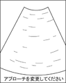
- FIG. 4 is a conceptual diagram of one embodiment showing a display screen of a monitor of an ultrasound diagnostic apparatus when notifying a message suggesting a change in approach of an ultrasound probe;
- FIG. 11 is a conceptual diagram of another embodiment showing a display screen of a monitor of an ultrasonic diagnostic apparatus when notifying a message suggesting a change in the approach of the ultrasonic probe;
- FIG. 1 is a block diagram of one embodiment showing the configuration of the ultrasonic diagnostic apparatus of the present invention.
- the ultrasonic diagnostic apparatus shown in FIG. 1 is a stationary ultrasonic diagnostic apparatus and includes an ultrasonic probe 1 and an apparatus body 3 connected to the ultrasonic probe 1 .
- the ultrasonic probe 1 scans the inspection location of the subject with an ultrasonic beam and outputs sound ray signals corresponding to the ultrasonic image of this inspection location.
- the ultrasonic probe 1 includes a transducer array 11, a transmission/reception circuit 14, a motion sensor 12, and a pressure sensor 13, as shown in FIG.
- the transducer array 11 and the transmission/reception circuit 14 are bidirectionally connected.
- the transmitting/receiving circuit 14, the motion sensor 12 and the pressure sensor 13 are connected to a device controller 36 of the device body 3, which will be described later.
- the transducer array 11 has a plurality of ultrasonic transducers arranged one-dimensionally or two-dimensionally. These transducers transmit ultrasonic waves in accordance with drive signals supplied from the transmitting/receiving circuit 14, receive reflected waves from the subject, and output analog reception signals.
- Each vibrator includes, for example, a piezoelectric ceramic typified by PZT (Lead Zirconate Titanate), a polymeric piezoelectric element typified by PVDF (Poly Vinylidene Di Fluoride), and PMN-PT ( Lead Magnesium Niobate-Lead Titanate: A piezoelectric single crystal represented by lead magnesium niobate-lead titanate solid solution).
- the transmission/reception circuit 14 causes the transducer array 11 to transmit ultrasonic waves, and performs reception focusing processing on reception signals output from the transducer array 11 that have received ultrasonic echoes. to generate a sound ray signal.
- the transmission/reception circuit 14 includes a pulser 51 connected to the transducer array 11, an amplifier 52 connected in series from the transducer array 11, an AD (Analog Digital) converter 53, and a beamformer 52. 54 and .
- the pulsar 51 includes, for example, a plurality of pulse generators, and ultrasonic waves transmitted from a plurality of transducers of the transducer array 11 generate ultrasonic beams based on a transmission delay pattern selected by the device control unit 36. Each drive signal is supplied to a plurality of transducers with the delay amount adjusted so as to form a waveform.
- a pulsed or continuous wave voltage is applied to the electrodes of the transducers of the transducer array 11
- the piezoelectric body expands and contracts, and pulsed or continuous wave ultrasonic waves are generated from the respective transducers.
- an ultrasonic beam is formed from the composite wave of these ultrasonic waves.
- the transmitted ultrasonic beam is reflected by an object such as a part of the subject and propagates toward the transducer array 11 of the ultrasonic probe 1 .
- Each transducer constituting the transducer array 11 expands and contracts upon receiving the ultrasonic echo propagating toward the transducer array 11 in this way, generates a reception signal that is an electrical signal, and receives these signals.
- a signal is output to the amplifier 52 .
- the amplification unit 52 amplifies the signal input from each transducer that constitutes the transducer array 11 and transmits the amplified signal to the AD conversion unit 53 .
- the AD converter 53 converts the analog signal transmitted from the amplifier 52 into digital received data and outputs the received data to the beamformer 54 .
- the beamformer 54 adds each delay to each received data converted by the AD converter 53 according to the sound velocity or the distribution of the sound velocity set based on the reception delay pattern selected by the device controller 36. By doing so, so-called reception focus processing is performed. By this reception focusing process, each piece of reception data converted by the AD conversion unit 53 is phased and added, and an acoustic ray signal in which the focus of the ultrasonic echo is narrowed down is generated.
- the motion sensor 12 detects motion of the ultrasonic probe 1 .
- the pressure sensor 13 detects the pressure applied to the ultrasonic probe 1 when the ultrasonic probe 1 is brought into contact with the inspection site of the subject.
- the device main body 3 generates an ultrasonic image of the examination location of the subject based on the sound ray signal generated by the ultrasonic probe 1, and displays the ultrasonic image of the examination location of the subject.
- the device main body 3 includes an image generation unit 31, an image memory 32, a flight processing unit 35, a display control unit 33, a monitor (display unit) 34, an input device 37, and a device control unit. a portion 36;
- the image generation unit 31 is connected to the transmission/reception circuit 14, and the display control unit 33 and the monitor 34 are sequentially connected to the image generation unit 31.
- An image memory 32 and a feces processing unit 35 are connected to the image generation unit 31
- a display control unit 33 is connected to the image memory 32 and the feces processing unit 35 .
- the image generating section 31 , the display control section 33 , the image memory 32 and the flight processing section 35 are connected to the device control section 36 , which is connected to the input device 37 .
- the image generation unit 31 scans the examination location of the subject with an ultrasonic beam using the ultrasonic probe 1 (more strictly, the transducer array 11). Based on the received signal, more specifically, based on the sound ray signal generated from the received signal by the transmitting/receiving circuit 14, an ultrasonic image (ultrasonic image signal) of the examination location of the subject is generated.
- the image generator 31 has a configuration in which a signal processor 16, a DSC (Digital Scan Converter) 18, and an image processor 17 are connected in series.
- the signal processing unit 16 generates image information data corresponding to the ultrasonic image based on the acoustic ray signal generated by the transmission/reception circuit 14 . More specifically, the signal processing unit 16 performs signal processing on the sound ray signal generated by the beamformer 54 of the transmission/reception circuit 14, for example, attenuation due to propagation distance according to the depth of the position where the ultrasonic wave is reflected. After performing the correction of , envelope detection processing is performed to generate image information data representing tomographic image information regarding tissue in the subject.
- the DSC 18 raster-converts the image information data generated by the signal processing unit 16 into an image signal that conforms to the normal television signal scanning method.
- the image processing unit 17 performs various corrections such as brightness correction, gradation correction, sharpness correction, image size correction, refresh rate correction, scanning frequency correction, and color correction on the image signal input from the DSC 18 according to the display format of the monitor 34 .
- an ultrasonic image (ultrasonic image signal) is generated, and the ultrasonic image subjected to the image processing is output to the image memory 32 , the fecal processing unit 35 and the display control unit 33 .
- the image memory 32 is a memory that stores a series of multiple frames of ultrasound images (ultrasound image signals) generated for each examination by the image generation unit 31 under the control of the device control unit 36 .
- the image memory 32 includes flash memory, HDD (Hard Disk Drive), SSD (Solid State Drive), FD (Flexible Disc), MO disc (Magneto-Optical disc). ), MT (Magnetic Tape), RAM (Random Access Memory), CD (Compact Disc), DVD (Digital Versatile Disc), SD card (Secure Digital card)
- a recording medium such as a digital card), a USB memory (Universal Serial Bus memory), or an external server can be used.
- the display control unit 33 causes the monitor 34 to display various information under the control of the device control unit 36 .
- the display control unit 33 performs predetermined processing on the ultrasonic image generated by the image generating unit 31 or the ultrasonic image stored in the image memory 32, and displays the processed ultrasonic image on the monitor 34. to display.
- the monitor 34 displays various information under the control of the display control unit 33.
- the monitor 34 displays, for example, an ultrasound image.
- Examples of the monitor 34 include an LCD (Liquid Crystal Display) and an organic EL (Electro-Luminescence) display.
- the input device 37 receives various instructions input by the user (examiner) of the ultrasonic diagnostic apparatus.
- the input device 37 is not particularly limited, but includes various buttons, a voice input device for inputting various instructions using voice recognition, and a GUI (Graphical User Interface) displayed on the monitor 34 by the user. ) includes a touch panel or the like for inputting various instructions by performing a touch operation on the screen.
- the device control section 36 controls each section of the ultrasonic probe 1 and the device main body 3 based on a program stored in advance and user's instructions input from the input device 37 .
- the stool processing unit 35 Under the control of the device control unit 36, the stool processing unit 35 performs various processing related to stool, including identifying the presence or absence of stool in the ultrasound image and identifying the stool properties in the stool region. As shown in FIG. 4, the flight processing unit 35 includes a flight information detection unit 41, a flight identification unit 42, a contact detection unit 45, a motion detection unit 47, a flight information display unit 43, and an approach determination unit 46. , a notification unit 44 and a mode switching unit 48 .
- the flight information detection unit 41 is connected to the image generation unit 31.
- a flight identification unit 42 and a flight information display unit 43 are sequentially connected to the flight information detection unit 41 , and the display control unit 33 is connected to the flight information display unit 43 .
- the flight information display section 43 is connected to the contact detection section 45 .
- the notification unit 44 is connected to each of the flight identification unit 42 , the contact detection unit 45 , the approach determination unit 46 and the motion detection unit 47 .
- each section of the flight processing section 35 is connected to the mode switching section 48 .
- the stool information detection unit 41 detects various information related to stool from the ultrasound image by analyzing the ultrasound image.
- the stool information detection unit 41 detects, for example, a stool region, which is a region in which stool may be present, from an ultrasound image.
- the stool information detection unit 41 also detects stool property information, which is information about the stool property of the stool region, from the ultrasound image.
- the method of detecting the stool region is not particularly limited. A stool area can be detected.
- the stool information detection unit 41 When detecting a stool region from an ultrasound image using template matching, the stool information detection unit 41 prepares a plurality of templates having different sizes, shapes, textures, etc. within the region of interest, and uses each of the plurality of templates. By raster-scanning the inside of the ultrasound image with the scanner, a region whose correlation value with the template is equal to or greater than a predetermined threshold value is detected as a fecal region.
- the stool information detection unit 41 When the stool information detection unit 41 detects a stool region from an ultrasound image using machine learning using image feature quantities, the stool information detection unit 41 prepares a plurality of teacher images including an anatomical structure and a stool region, and detects a region of interest. is converted into a feature vector (image quantization), and machine learning is performed using machine learning algorithms such as Adaboost (Adaptive Boosting) and SVM (Support Vector Machine) to detect fecal regions from ultrasound images. .
- Adaboost Adaptive Boosting
- SVM Small Vector Machine
- the stool information detection unit 41 detects a stool region from an ultrasound image using a deep learning model
- a large number of teacher images including anatomical structures and stool regions are prepared in advance, and a large number of teacher images are used.
- a deep learning model is created by learning the relationship between the teacher image and the stool region in the teacher image for a large number of teacher images, and the stool region is detected from the ultrasound image using this deep learning model.
- the stool identification unit 42 identifies the presence or absence of stool, in other words, whether or not the stool area is actually an area where stool is present, based on the detection result of the stool area. In addition to identifying the presence or absence of stool, the stool identification unit 42 further identifies the stool properties of the stool region based on the stool properties information.
- the method of identifying the presence or absence of stool is not particularly limited, but if the stool identification unit 42 identifies the presence or absence of stool but does not identify the nature of the stool, based on the detection results of the stool region in the ultrasound images of a plurality of frames.
- the presence or absence of stool can be specified.
- the stool identification unit 42 identifies that there is a stool when, for example, a stool region is detected from a predetermined number of ultrasound images or more among a plurality of consecutive frames of ultrasound images.
- the stool identification unit 42 identifies that there is stool when a stool region is detected from eight or more frames of ultrasonic images among consecutive ten frames of ultrasonic images.
- the stool identification unit 42 may identify that there is stool only when a stool region is detected in all ten frames of the ultrasonic images of the continuous ten frames.
- the stool identifying unit 42 performs the same determination to determine whether or not the stool regions in the ultrasonic images of adjacent frames are the same stool region. It is desirable to count the number of frames as the number of frames defined above. That is, the stool identification unit 42 counts the number of frames only when the stool regions detected from the ultrasonic images of adjacent frames are the same. As a result, fecal regions that are stably detected at the same position in ultrasonic images of adjacent frames can be identified as regions containing feces.
- the stool identifying unit 42 may, for example, determine an evaluation index by IoU (Intersection over Union) of the stool region in the ultrasound images of adjacent frames, that is, the flight area in the ultrasound images between the frames. By obtaining the degree of overlap of the regions and comparing this evaluation index with the threshold value, it is possible to determine whether or not the fecal regions are the same. For example, when the evaluation index is equal to or greater than a threshold value, the flight identification unit 42 determines that the flight regions are the same.
- IoU Intersection over Union
- the stool identification unit 42 selects a predetermined number of ultrasound images or more among a plurality of consecutive frames of ultrasound images for each stool region. If a stool area is detected from the , it is identified that there is stool. In this case as well, it is desirable that the stool identification unit 42 performs the same determination of the stool regions in the ultrasonic images of adjacent frames for each stool region.
- the stool identification unit 42 may identify whether or not there is stool based on the detection result of the stool region in only one frame of the ultrasound image. In this case, the stool identification unit 42 identifies that there is stool when, for example, a stool region is detected from one frame of the ultrasound image. That is, the stool identification unit 42 identifies that there is stool when a stool region is detected even in one frame of the ultrasound image.
- the stool identification unit 42 identifies stool from ultrasonic images of a predetermined number of frames or more among a plurality of consecutive frames of ultrasonic images. If a region is detected, and the stool regions detected from the ultrasound images of a predetermined number of frames or more out of the ultrasound images of the first number of frames or more have the same stool properties, there is stool. can be specified.
- the stool identification unit 42 determines whether the stool region is the same, and determines the number of frames of the ultrasound images in which the same stool region is detected to be the predetermined first frame number and the predetermined second frame number. It is preferable to count as a number.
- the stool identification unit 42 determines that there is stool when a stool region is detected from one frame of the ultrasonic image and the stool properties of the stool region detected from the one frame of ultrasonic image are identified. may be specified.
- the stool identification unit 42 can identify the presence or absence of stool based on the detection result of the stool region detected by the deep learning model.
- the stool information detection unit 41 may use a deep learning model to detect only the stool region from the ultrasound image, or may detect the stool region and the probability that this stool region is a stool region. good.
- the stool information detection unit 41 detects the stool area as a rectangular area using, for example, a deep learning model. Then, the stool identification unit 42 identifies that there is stool when the stool region is detected, and identifies that there is no stool when the stool region is not detected.
- the stool information detection unit 41 detects the stool region as a rectangular region for each frame of the ultrasound image using, for example, a deep learning model. , find the location of the stool region and the probability that this stool region is a stool region. Then, the stool identification unit 42 identifies the presence or absence of stool by comparing the statistical value of the probability of the ultrasound images of a plurality of frames, such as the average value, weighted average value, or median value, with a threshold value. The flight identification unit 42 identifies that there is a flight, for example, when the statistical value of the probability of being the region of the flight is equal to or greater than a threshold.
- the stool information detection unit 41 may detect the probability that each pixel of the ultrasonic image is a stool pixel using a deep learning model.
- the stool information detection unit 41 uses, for example, a deep learning model to detect the probability that the pixel is a stool pixel for each frame of the ultrasound image and for each pixel of the ultrasound image.
- a first threshold value By comparing the probability of being a pixel with a first threshold value, it is determined whether or not the pixel is a normal pixel. For example, when the probability is equal to or greater than the first threshold, the flight information detection unit 41 determines that the pixel is a flight pixel. Then, the flight information detection unit 41 detects an aggregate (lump) of a plurality of pixels determined to be pixels of flight as a flight region.
- the stool identifying unit 42 obtains, as an index value, a statistical value of probabilities of all pixels in the stool region of one frame of the ultrasound image, such as an average value, a weighted average value, or a median value, and Presence or absence of stool is identified by comparing the statistical value of the index values of the ultrasound image, such as the average value, weighted average value or median value, with the second threshold.
- the flight identifying unit 42 identifies that there is a flight, for example, when the statistical value of the index value is equal to or greater than the second threshold.
- the flight identification unit 42 make the same determination and detect the same flight region.
- the stool specifying unit 42 specifies the stool properties based on the luminance value of the stool area or based on the stool properties information detected by the deep learning model. be able to.
- the stool information detection unit 41 detects the stool region from the ultrasound image, and obtains statistics of the stool region brightness for each frame of the ultrasound image. A value such as an average value, a weighted average value, or a median value is detected, and the stool identification unit 42 compares the statistic value of the luminance in the stool region with the third threshold for each frame of the ultrasound image. A first comparison result is obtained, and stool properties are specified based on the first comparison result in one or more frames of the ultrasound image.
- the stool is hard, if the 6th threshold is smaller than the 5th threshold and is lower than the 5th threshold, it is normal stool, and if the statistic is lower than the 6th threshold identified as loose stools.
- the stool information detection unit 41 detects a stool region from the ultrasonic image for each frame of the ultrasonic image, and calculates the statistic value of the luminance in the stool region and the luminance in a predetermined region around the stool region.
- the stool identification unit 42 obtains a second comparison result by comparing the luminance ratio with a fourth threshold value for each frame of the ultrasound image, and obtains a second comparison result for one frame or a plurality of frames.
- the stool properties may be specified based on the second comparison result in the ultrasound image.
- the luminance ratio is equal to or higher than the 5th threshold, hard stools, the 6th threshold smaller than the 5th threshold or higher, and less than the 5th threshold are normal stools, and the 6th threshold is lower than the Identify loose stools.
- the stool properties are specified based on the luminance values of the stool areas, there may be cases where the stool areas are detected but the stool properties are unknown.
- the stool information detection unit 41 When identifying stool properties based on stool properties information detected by a deep learning model, the stool information detection unit 41 simultaneously detects stool regions and stool properties information using, for example, a deep learning model. Then, the stool identification unit 42 identifies the presence or absence of stool based on the stool region detected by the deep learning model, and identifies stool properties based on the stool properties information detected by the deep learning model. In this case, the stool information detection unit 41 may detect the probability that the stool region is in each class of stool properties, such as the probability that the stool region is hard stool, soft stool, normal stool, or background, or , for each pixel in the ultrasound image, the probability that the pixel is in each class of stool properties may be detected.
- the stool information detection unit 41 detects, for example, a rectangular region as a stool region using a deep learning model. Find the probability that . Then, the stool identification unit 42 identifies the class with the highest probability among the stool attribute classes as the stool attribute of the stool area.
- the stool information detection unit 41 uses a deep learning model, for example, to detect whether the pixel is convenient for each pixel of the ultrasonic image. The probability of being in each class of properties is detected, and the class with the highest probability among the classes of stool properties is determined as the class of the pixel. Then, the flight information detection unit 41 detects an aggregate (lump) of a plurality of pixels determined to be flight pixels based on the pixel class as a flight region. In this case, one stool area may include a plurality of pixels of different classes. In response to this, the stool identification unit 42 obtains the total area of each class of stool properties, and identifies the class with the largest total area as the stool properties of the stool region.
- a deep learning model for example, to detect whether the pixel is convenient for each pixel of the ultrasonic image. The probability of being in each class of properties is detected, and the class with the highest probability among the classes of stool properties is determined as the class of the pixel. Then, the flight information detection unit 41 detects an aggregate (lump)
- the contact detection unit 45 detects whether or not the ultrasonic probe 1 is in contact with the inspection location of the subject when performing scanning.
- the contact detection unit 45 is not particularly limited, but for example, based on at least one of the analysis result of the ultrasonic image and the pressure detection result by the pressure sensor 13, whether the ultrasonic probe 1 is in contact with the examination location of the subject. It is possible to detect whether or not
- the motion detection unit 47 detects whether or not the ultrasonic probe 1 moves during scanning. For example, the motion detection unit 47 detects the presence or absence of motion of the ultrasonic probe 1 for each frame of the ultrasonic image after scanning is started.
- the motion detection unit 47 is not particularly limited, but for example, the image analysis result of the ultrasonic image, the motion detection result by the motion sensor 12 provided in the ultrasonic probe 1, and the pressure sensor provided in the ultrasonic probe 1
- the presence or absence of movement of the ultrasonic probe 1 can be detected based on at least one of the pressure detection results by 13 .
- the pressure detection result of the pressure sensor 13 changes only when the ultrasonic probe 1 is moving. Therefore, by comparing the amount of change in pressure detected by the pressure sensor 13 with the threshold value, it is possible to detect the presence or absence of movement of the ultrasonic probe 1 . For example, when the amount of change is equal to or greater than a threshold, it is detected that the ultrasonic probe 1 is moving.
- the flight information display unit 43 causes the monitor 34 to display various information related to flights. For example, when the presence of stool is identified, the stool information display unit 43 highlights the stool region in the ultrasound image displayed on the monitor 34 .
- the method for highlighting the stool region is not particularly limited, but for example, a contour line may be created by detecting the contour of the stool region, and the contour line may be displayed superimposed on the contour of the stool region.
- An area larger than the stool area, including the stool area, may be enclosed by creating an encircling line of any shape, such as circles and squares.
- the contour line or encircling line may be displayed in a predetermined display color, a predetermined line type, or a predetermined thickness.
- a mask may be created by coloring the inside of the stool area in a predetermined display color and filling it, and this mask may be displayed superimposed on the stool area.
- the approach determination unit 46 determines the approach of the ultrasonic probe 1 when scanning. In other words, the approach determination unit 46 determines the approach of the ultrasound probe 1 currently being scanned.
- the approach of the ultrasonic probe 1 includes, for example, a rectal longitudinal cross-section approach in which the ultrasound probe 1 is oriented vertically and the abdomen of the subject is scanned from the front side of the subject, and an approach in which the ultrasound probe 1 is oriented horizontally and the front surface of the subject is scanned.
- a rectal cross-sectional approach in which the subject's abdomen is scanned from the side
- a transgluteal cleft approach in which an ultrasound probe is used to scan the subject's abdomen through the gluteal cleft on the dorsal side of the subject.
- the approach determination method is not particularly limited. approach can be determined from
- the notification unit 44 notifies the user of various messages. For example, when it is not specified that there will be a flight within a predetermined period, the reporting unit 44 reports a message suggesting a change in the approach of the ultrasound probe 1 during scanning.
- the predetermined period is not particularly limited, it is assumed to be a period during which the presence or absence of stool can be identified based on the detection result of the stool region at the test site of the subject.
- the length of this predetermined period is not particularly limited, for example, a period during which the inspection site of the subject is scanned, a period during which the inspection site of the subject is inspected, and an ultrasonic probe is used to inspect the subject.
- the period of time during which the ultrasonic probe is placed against the test site of the subject such as the period of contact with the site, or the period from only the time when the ultrasonic probe is detected to be in motion. good too.
- the predetermined period of time can also be a fixed period of time, for example 5 seconds, 10 seconds, 20 seconds, or a maximum amount of time that the test site of the subject is scanned. For example, 20 seconds, 30 seconds, 1 minute, etc.
- the measurement for the predetermined period is not particularly limited, but may be started immediately after the scan is started, for example.
- the measurement for the predetermined period is started immediately after the inspection of the inspection site of the subject is started, in other words, immediately after the function of inspecting for constipation (existence of stool) is activated in the ultrasonic diagnostic apparatus. You can start from Moreover, the measurement for the predetermined period may be started immediately after the contact detection unit 45 detects that the ultrasonic probe 1 is in contact with the examination location of the subject. Furthermore, only the time during which the motion detector 47 detects that the ultrasonic probe 1 moves may be measured as a predetermined period.
- the method of announcing the message is not particularly limited, but for example, the message may be displayed on the monitor 34 under the control of the display control unit 33, or the message may be read out by a speaker (not shown). or both at the same time.
- the ultrasonic diagnostic apparatus has a first operating mode that specifies neither the presence or absence of stool nor stool properties, a second operating mode that specifies the presence or absence of stool but does not specify stool properties, and the presence or absence of stool and stool properties. at least two of a third mode of operation specifying both of The mode switching unit 48 switches to one of the above-described at least two operation modes according to a user's instruction input using a GUI, voice recognition, or the like.
- the image generation unit 31, the flight processing unit 35, the display control unit 33 and the device control unit 36 are configured by the processor 39.
- the transmitting/receiving circuit 14 starts transmitting ultrasonic waves under the control of the device control unit 36, and an acoustic ray signal is generated. (step S1).
- ultrasonic beams are transmitted from the plurality of transducers of the transducer array 11 to the inspected portion of the subject according to the drive signal from the pulser 51 .
- An ultrasonic echo from an inspection location based on an ultrasonic beam transmitted from the pulsar 51 is received by each transducer of the transducer array 11, and each transducer of the transducer array 11 that has received the ultrasonic echo outputs an analog signal.
- a received signal is output.
- a received signal output from each transducer of the transducer array 11 is amplified by the amplifier 52 and AD-converted by the AD converter 53 to obtain received data.
- a sound ray signal is generated by subjecting the received data to reception focusing processing by the beamformer 54 .
- the image generation unit 31 generates an ultrasonic image (ultrasound image) of the examination location of the subject based on the sound ray signal generated by the beamformer 54 of the transmission/reception circuit 14. signal) is generated (step S2).
- the sound ray signal generated by the beamformer 54 is subjected to various signal processing by the signal processing unit 16 to generate image information data representing tomographic image information regarding tissues in the subject.
- the image information data generated by the signal processing unit 16 is raster-converted by the DSC 18 and further subjected to various image processing by the image processing unit 17 to generate an ultrasonic image (ultrasonic image signal).
- the ultrasound image generated by the image processing unit 17 is stored in the image memory 32 .
- the display control unit 33 performs predetermined processing on the ultrasonic image generated by the image processing unit 17 or the ultrasonic image stored in the image memory 32. It is displayed on the monitor 34 (step S3).
- the operation until an ultrasonic image is generated and displayed on the monitor 34 is the same as in the first operation mode.
- the stool information detection unit 41 analyzes the ultrasonic image and detects a stool region from the ultrasonic image. (Step S11).
- step S12 the presence or absence of flights is specified by the flight specifying unit 42 based on the detection result of the flight region.
- step S13 when the presence of stool is identified (Yes in step S13), the stool area is displayed on the ultrasound image displayed on the monitor 34 by the stool information display unit 43 under the control of the display control unit 33. It is highlighted (step S14).
- the stool information display unit 43 creates, for example, a mask 49 for highlighting the stool region, and superimposes the mask 49 on the stool region of the ultrasound image displayed on the monitor 34 as shown in FIG. to display.
- the notification unit 44 may notify a message indicating that there is a flight. For example, as shown in FIG. 9, a message such as "Flight detected" may be displayed on the monitor 34.
- FIG. 9 a message such as "Flight detected" may be displayed on the monitor 34.
- the notification unit 44 notifies a message proposing a change in the approach of the ultrasound probe 1 when performing scanning. (step S15). For example, as shown in FIG. 10, a message such as "Please change your approach" is displayed on the monitor 34. FIG. The user changes the approach according to the message and redo the scan.
- the stool region is highlighted in the ultrasonic image displayed on the monitor 34. Therefore, the user can easily detect the presence of stool in the ultrasonic image. The area can be easily grasped. In addition, even if it is not specified that there will be a flight within the predetermined period, a message suggesting a change in approach is notified. can be identified with certainty.
- stool condition information can be detected after detecting stool regions, or stool regions and stool condition information can be detected at the same time.
- the case of detecting stool properties information after detecting a stool region in the third operation mode will be described.
- the operation until an ultrasonic image is generated and displayed on the monitor 34 is the same as in the first operation mode.
- the stool information detection unit 41 analyzes the ultrasonic image and detects a stool region from the ultrasonic image. (Step S21).
- the presence or absence of flights is specified by the flight specifying unit 42 based on the detection result of the flight region (step S22).
- step S23 when it is not specified that there will be a flight within the predetermined period (No in step S23), the process proceeds to step S28.
- the stool information detection unit 41 further detects stool condition information of the stool region from the ultrasound image (step S24).
- the stool identification unit 42 further identifies the stool properties of the stool region based on the stool properties information (step S25).
- the notification unit 44 may notify a message indicating that there is a flight, may notify a message indicating the nature of the stool, or may notify both of these messages.
- step S28 the notification unit 44 A message proposing a change is broadcast (step S28). The user changes the approach according to the message and redo the scan.
- the stool information detection unit 41 simultaneously detects the stool area and the stool condition information of this stool area using, for example, a deep learning model (step S31).
- the presence or absence of stool is specified by the stool specifying unit 42 based on the detection result of the stool area (step S32), and the stool properties are specified based on the stool properties information (step S33).
- the subsequent operations from steps S34 to S36 are the same as the operations from steps S26 to S28 in the case of detecting stool condition information after detecting a stool region.
- the stool region is highlighted in the ultrasonic image displayed on the monitor 34.
- the user can easily grasp the stool region in the ultrasound image.
- a message suggesting a change in approach is announced. Therefore, the user can reliably identify the presence or absence of flights by changing the approach according to the message.
- the notification unit 44 may suggest a change to an approach different from the current approach when it is not specified that there will be a flight within a predetermined period.
- the approach determination unit 46 determines the approach of the ultrasonic probe 1 currently being scanned. Then, when the notifying unit 44 does not specify that there is a flight within a predetermined period, based on the approach determination result of the approach determining unit 46, the current approach is selected from a plurality of preset approaches. A different approach is selected and a message is broadcast suggesting a change to a different approach than the current approach. In addition, the notification unit 44 may notify a message indicating that there is no flight when it is not specified that there is a flight by all of a plurality of preset approaches.
- the notification unit 44 selects an approach different from the rectal cross-section approach from among a plurality of preset approaches.
- a longitudinal rectal approach is selected and a message is broadcast suggesting a change to this longitudinal rectal approach. For example, as shown in FIG. 11, a message such as "Please change to longitudinal section" may be displayed on the monitor 34.
- FIG. 11 a message such as "Please change to longitudinal section" may be displayed on the monitor 34.
- the method of selecting an approach different from the current approach from among a plurality of preset approaches is not particularly limited, but for example, the order of selection is determined in advance, and sequentially according to this predetermined selection order can be selected.
- the present invention is not limited to a stationary ultrasonic diagnostic apparatus, but also a portable ultrasonic diagnostic apparatus in which the device main body 3 is realized by a laptop terminal device, and a smartphone or a tablet PC (Personal The present invention can also be applied to a handheld ultrasonic diagnostic apparatus realized by a handheld terminal device such as a computer (personal computer).
- the ultrasonic probe 1 and the apparatus main body 3 may be connected by wire or wirelessly.
- all of the image generating section 31 or only the signal processing section 16 may be provided on the ultrasonic probe 1 side, or may be provided on the device main body 3 side.
- the hardware configuration of a processing unit (processing unit) that executes various processes such as the transmission/reception circuit 14, the image generation unit 31, the display control unit 33, the flight processing unit 35, and the device control unit 36 is , dedicated hardware, or various processors or computers that execute programs.
- the circuit configuration can be changed after manufacturing such as CPU (Central Processing Unit), FPGA (Field Programmable Gate Array), etc., which are general-purpose processors that run software (programs) and function as various processing units.
- Programmable Logic Device PLD
- ASIC Application Specific Integrated Circuit
- One processing unit may be composed of one of these various processors, or a combination of two or more processors of the same or different type, such as a combination of multiple FPGAs, or a combination of FPGAs and CPUs. and so on. Also, the plurality of processing units may be configured by one of various processors, or two or more of the plurality of processing units may be combined into one processor.
- SoC System on Chip
- the hardware configuration of these various processors is, more specifically, an electric circuit that combines circuit elements such as semiconductor elements.
- the method of the present invention can be implemented, for example, by a program for causing a computer to execute each step. It is also possible to provide a computer-readable recording medium on which this program is recorded.
- an ultrasound probe ; a monitor; a processor; The processor generating an ultrasound image based on a received signal obtained by scanning an inspection location of a subject with an ultrasound beam using the ultrasound probe; displaying the ultrasound image on the monitor; detecting a stool region from the ultrasound image; Identifying the presence or absence of stool based on the detection result of the stool region; highlighting the stool region in the ultrasonic image displayed on the monitor when the presence of the stool is identified;
- An ultrasound diagnostic apparatus configured to issue a message suggesting a change in the approach of the ultrasound probe when performing the scan when the presence of the flight is not identified within a predetermined period of time.
Landscapes
- Health & Medical Sciences (AREA)
- Life Sciences & Earth Sciences (AREA)
- Engineering & Computer Science (AREA)
- Physics & Mathematics (AREA)
- Medical Informatics (AREA)
- Animal Behavior & Ethology (AREA)
- Radiology & Medical Imaging (AREA)
- Nuclear Medicine, Radiotherapy & Molecular Imaging (AREA)
- Biomedical Technology (AREA)
- Heart & Thoracic Surgery (AREA)
- Biophysics (AREA)
- Molecular Biology (AREA)
- Surgery (AREA)
- Pathology (AREA)
- General Health & Medical Sciences (AREA)
- Public Health (AREA)
- Veterinary Medicine (AREA)
- Acoustics & Sound (AREA)
- Physiology (AREA)
- Computer Vision & Pattern Recognition (AREA)
- Ultra Sonic Daignosis Equipment (AREA)
Priority Applications (3)
| Application Number | Priority Date | Filing Date | Title |
|---|---|---|---|
| EP22828099.6A EP4360565A4 (en) | 2021-06-24 | 2022-05-16 | ULTRASONIC DIAGNOSTIC DEVICE AND METHOD FOR CONTROLLING ULTRASONIC DIAGNOSTIC DEVICE |
| JP2023529689A JPWO2022270180A1 (https=) | 2021-06-24 | 2022-05-16 | |
| US18/539,215 US20240108307A1 (en) | 2021-06-24 | 2023-12-13 | Ultrasound diagnostic apparatus and control method for ultrasound diagnostic apparatus |
Applications Claiming Priority (2)
| Application Number | Priority Date | Filing Date | Title |
|---|---|---|---|
| JP2021-105119 | 2021-06-24 | ||
| JP2021105119 | 2021-06-24 |
Related Child Applications (1)
| Application Number | Title | Priority Date | Filing Date |
|---|---|---|---|
| US18/539,215 Continuation US20240108307A1 (en) | 2021-06-24 | 2023-12-13 | Ultrasound diagnostic apparatus and control method for ultrasound diagnostic apparatus |
Publications (1)
| Publication Number | Publication Date |
|---|---|
| WO2022270180A1 true WO2022270180A1 (ja) | 2022-12-29 |
Family
ID=84544505
Family Applications (1)
| Application Number | Title | Priority Date | Filing Date |
|---|---|---|---|
| PCT/JP2022/020305 Ceased WO2022270180A1 (ja) | 2021-06-24 | 2022-05-16 | 超音波診断装置および超音波診断装置の制御方法 |
Country Status (4)
| Country | Link |
|---|---|
| US (1) | US20240108307A1 (https=) |
| EP (1) | EP4360565A4 (https=) |
| JP (1) | JPWO2022270180A1 (https=) |
| WO (1) | WO2022270180A1 (https=) |
Families Citing this family (1)
| Publication number | Priority date | Publication date | Assignee | Title |
|---|---|---|---|---|
| CN116159254A (zh) * | 2022-12-30 | 2023-05-26 | 深圳半岛医疗有限公司 | 超声治疗头控制方法、超声治疗设备以及存储介质 |
Citations (3)
| Publication number | Priority date | Publication date | Assignee | Title |
|---|---|---|---|---|
| JP2016195748A (ja) * | 2015-04-06 | 2016-11-24 | 国立大学法人 熊本大学 | 診断装置及び診断方法 |
| JP6162493B2 (ja) | 2013-06-11 | 2017-07-12 | 東芝メディカルシステムズ株式会社 | 超音波診断装置 |
| WO2020044758A1 (ja) * | 2018-08-29 | 2020-03-05 | 富士フイルム株式会社 | 超音波診断装置および超音波診断装置の制御方法 |
Family Cites Families (10)
| Publication number | Priority date | Publication date | Assignee | Title |
|---|---|---|---|---|
| WO2007046019A1 (en) * | 2005-10-21 | 2007-04-26 | Koninklijke Philips Electronics, N.V. | Rendering method and apparatus |
| BR112012012819A2 (pt) * | 2009-11-27 | 2016-08-16 | Dog Microsystems Inc | método e sistema para filtrar dados de imagem e uso dos mesmos na endoscopia virtual |
| US20160310110A1 (en) * | 2015-04-23 | 2016-10-27 | Siemens Medical Solutions Usa, Inc. | Acquisition control for mixed mode ultrasound imaging |
| US10346982B2 (en) * | 2016-08-22 | 2019-07-09 | Koios Medical, Inc. | Method and system of computer-aided detection using multiple images from different views of a region of interest to improve detection accuracy |
| CN111670010B (zh) * | 2018-01-31 | 2024-01-16 | 富士胶片株式会社 | 超声波诊断装置及超声波诊断装置的控制方法 |
| JP2020039646A (ja) * | 2018-09-11 | 2020-03-19 | 株式会社日立製作所 | 超音波診断装置及びボリュームデータ取込方法 |
| EP3865074B1 (en) * | 2018-10-12 | 2024-10-23 | FUJIFILM Corporation | Ultrasonic diagnostic device and control method for ultrasonic diagnostic device |
| WO2020075449A1 (ja) * | 2018-10-12 | 2020-04-16 | 富士フイルム株式会社 | 超音波診断装置および超音波診断装置の制御方法 |
| CN114727806A (zh) * | 2019-11-21 | 2022-07-08 | 皇家飞利浦有限公司 | 照护点超声(pocus)扫描辅助和相关装置、系统和方法 |
| IT202100004376A1 (it) * | 2021-02-25 | 2022-08-25 | Esaote Spa | Metodo di determinazione di piani di scansione nell’acquisizione di immagini ecografiche e sistema ecografico per l’attuazione del detto metodo |
-
2022
- 2022-05-16 JP JP2023529689A patent/JPWO2022270180A1/ja active Pending
- 2022-05-16 EP EP22828099.6A patent/EP4360565A4/en active Pending
- 2022-05-16 WO PCT/JP2022/020305 patent/WO2022270180A1/ja not_active Ceased
-
2023
- 2023-12-13 US US18/539,215 patent/US20240108307A1/en active Pending
Patent Citations (4)
| Publication number | Priority date | Publication date | Assignee | Title |
|---|---|---|---|---|
| JP6162493B2 (ja) | 2013-06-11 | 2017-07-12 | 東芝メディカルシステムズ株式会社 | 超音波診断装置 |
| JP2016195748A (ja) * | 2015-04-06 | 2016-11-24 | 国立大学法人 熊本大学 | 診断装置及び診断方法 |
| JP6592836B2 (ja) | 2015-04-06 | 2019-10-23 | 国立大学法人 熊本大学 | 診断装置及び診断方法 |
| WO2020044758A1 (ja) * | 2018-08-29 | 2020-03-05 | 富士フイルム株式会社 | 超音波診断装置および超音波診断装置の制御方法 |
Non-Patent Citations (1)
| Title |
|---|
| See also references of EP4360565A4 |
Also Published As
| Publication number | Publication date |
|---|---|
| JPWO2022270180A1 (https=) | 2022-12-29 |
| EP4360565A4 (en) | 2024-10-09 |
| EP4360565A1 (en) | 2024-05-01 |
| US20240108307A1 (en) | 2024-04-04 |
Similar Documents
| Publication | Publication Date | Title |
|---|---|---|
| WO2020075609A1 (ja) | 超音波診断装置および超音波診断装置の制御方法 | |
| JP7074871B2 (ja) | 超音波診断装置および超音波診断装置の制御方法 | |
| JP7719261B2 (ja) | 超音波システムおよび超音波システムの制御方法 | |
| JP7288550B2 (ja) | 超音波診断装置、超音波診断装置の制御方法および超音波診断装置用プロセッサ | |
| US12544034B2 (en) | Ultrasound diagnostic apparatus and operation method thereof | |
| WO2022044654A1 (ja) | 超音波診断装置および超音波診断装置の制御方法 | |
| US20240108307A1 (en) | Ultrasound diagnostic apparatus and control method for ultrasound diagnostic apparatus | |
| JP7848134B2 (ja) | 嚥下評価システムおよび嚥下評価方法 | |
| US12611164B2 (en) | Ultrasound diagnostic apparatus with function for highlight-displaying excrement region in ultrasound image and control method for ultrasound diagnostic apparatus | |
| WO2022230379A1 (ja) | 超音波診断装置および超音波診断装置の制御方法 | |
| US12303336B2 (en) | Ultrasound diagnostic apparatus and control method of ultrasound diagnostic apparatus | |
| JP2024001405A (ja) | 超音波診断装置および超音波診断装置の制御方法 | |
| JP2013240721A (ja) | 超音波診断装置 | |
| JP2007301181A (ja) | 超音波診断装置および画像表示方法 | |
| US12383231B2 (en) | Ultrasound diagnostic apparatus and control method of ultrasound diagnostic apparatus | |
| US12414757B2 (en) | Ultrasound diagnostic apparatus and control method for ultrasound diagnostic apparatus | |
| JP2024042416A (ja) | 超音波診断装置および超音波診断装置の制御方法 | |
| US20230240654A1 (en) | Ultrasound diagnostic apparatus and display method of ultrasound diagnostic apparatus | |
| JP2024064182A (ja) | 超音波診断装置および超音波診断装置の制御方法 | |
| JP2024039916A (ja) | 超音波診断装置および超音波診断装置の制御方法 | |
| JP2024039865A (ja) | 超音波診断装置および超音波診断装置の制御方法 | |
| JP2025099751A (ja) | 超音波診断装置、超音波診断装置の制御方法、及びプログラム | |
| JP2024025865A (ja) | 超音波診断装置の制御方法および超音波診断装置 | |
| JP2024068927A (ja) | 超音波診断システムの制御方法および超音波診断システム | |
| JP2024039872A (ja) | 超音波診断装置の制御方法および超音波診断装置 |
Legal Events
| Date | Code | Title | Description |
|---|---|---|---|
| 121 | Ep: the epo has been informed by wipo that ep was designated in this application |
Ref document number: 22828099 Country of ref document: EP Kind code of ref document: A1 |
|
| WWE | Wipo information: entry into national phase |
Ref document number: 2023529689 Country of ref document: JP |
|
| WWE | Wipo information: entry into national phase |
Ref document number: 2022828099 Country of ref document: EP |
|
| NENP | Non-entry into the national phase |
Ref country code: DE |
|
| ENP | Entry into the national phase |
Ref document number: 2022828099 Country of ref document: EP Effective date: 20240124 |